EP2576136B1 - Adaptive steuerung eines bearbeitungsprozesses - Google Patents
Adaptive steuerung eines bearbeitungsprozesses Download PDFInfo
- Publication number
- EP2576136B1 EP2576136B1 EP11725594.3A EP11725594A EP2576136B1 EP 2576136 B1 EP2576136 B1 EP 2576136B1 EP 11725594 A EP11725594 A EP 11725594A EP 2576136 B1 EP2576136 B1 EP 2576136B1
- Authority
- EP
- European Patent Office
- Prior art keywords
- tool
- workpiece
- machining
- grinding
- power
- Prior art date
- Legal status (The legal status is an assumption and is not a legal conclusion. Google has not performed a legal analysis and makes no representation as to the accuracy of the status listed.)
- Active
Links
Images


Classifications
-
- B—PERFORMING OPERATIONS; TRANSPORTING
- B23—MACHINE TOOLS; METAL-WORKING NOT OTHERWISE PROVIDED FOR
- B23Q—DETAILS, COMPONENTS, OR ACCESSORIES FOR MACHINE TOOLS, e.g. ARRANGEMENTS FOR COPYING OR CONTROLLING; MACHINE TOOLS IN GENERAL CHARACTERISED BY THE CONSTRUCTION OF PARTICULAR DETAILS OR COMPONENTS; COMBINATIONS OR ASSOCIATIONS OF METAL-WORKING MACHINES, NOT DIRECTED TO A PARTICULAR RESULT
- B23Q15/00—Automatic control or regulation of feed movement, cutting velocity or position of tool or work
- B23Q15/007—Automatic control or regulation of feed movement, cutting velocity or position of tool or work while the tool acts upon the workpiece
- B23Q15/12—Adaptive control, i.e. adjusting itself to have a performance which is optimum according to a preassigned criterion
-
- B—PERFORMING OPERATIONS; TRANSPORTING
- B23—MACHINE TOOLS; METAL-WORKING NOT OTHERWISE PROVIDED FOR
- B23F—MAKING GEARS OR TOOTHED RACKS
- B23F23/00—Accessories or equipment combined with or arranged in, or specially designed to form part of, gear-cutting machines
-
- B—PERFORMING OPERATIONS; TRANSPORTING
- B23—MACHINE TOOLS; METAL-WORKING NOT OTHERWISE PROVIDED FOR
- B23Q—DETAILS, COMPONENTS, OR ACCESSORIES FOR MACHINE TOOLS, e.g. ARRANGEMENTS FOR COPYING OR CONTROLLING; MACHINE TOOLS IN GENERAL CHARACTERISED BY THE CONSTRUCTION OF PARTICULAR DETAILS OR COMPONENTS; COMBINATIONS OR ASSOCIATIONS OF METAL-WORKING MACHINES, NOT DIRECTED TO A PARTICULAR RESULT
- B23Q15/00—Automatic control or regulation of feed movement, cutting velocity or position of tool or work
- B23Q15/007—Automatic control or regulation of feed movement, cutting velocity or position of tool or work while the tool acts upon the workpiece
- B23Q15/013—Control or regulation of feed movement
- B23Q15/04—Control or regulation of feed movement according to the final size of the previously-machined workpiece
-
- G—PHYSICS
- G05—CONTROLLING; REGULATING
- G05B—CONTROL OR REGULATING SYSTEMS IN GENERAL; FUNCTIONAL ELEMENTS OF SUCH SYSTEMS; MONITORING OR TESTING ARRANGEMENTS FOR SUCH SYSTEMS OR ELEMENTS
- G05B19/00—Programme-control systems
- G05B19/02—Programme-control systems electric
- G05B19/18—Numerical control [NC], i.e. automatically operating machines, in particular machine tools, e.g. in a manufacturing environment, so as to execute positioning, movement or co-ordinated operations by means of programme data in numerical form
- G05B19/182—Numerical control [NC], i.e. automatically operating machines, in particular machine tools, e.g. in a manufacturing environment, so as to execute positioning, movement or co-ordinated operations by means of programme data in numerical form characterised by the machine tool function, e.g. thread cutting, cam making, tool direction control
- G05B19/186—Generation of screw- or gearlike surfaces
-
- Y—GENERAL TAGGING OF NEW TECHNOLOGICAL DEVELOPMENTS; GENERAL TAGGING OF CROSS-SECTIONAL TECHNOLOGIES SPANNING OVER SEVERAL SECTIONS OF THE IPC; TECHNICAL SUBJECTS COVERED BY FORMER USPC CROSS-REFERENCE ART COLLECTIONS [XRACs] AND DIGESTS
- Y10—TECHNICAL SUBJECTS COVERED BY FORMER USPC
- Y10T—TECHNICAL SUBJECTS COVERED BY FORMER US CLASSIFICATION
- Y10T29/00—Metal working
- Y10T29/49—Method of mechanical manufacture
- Y10T29/49462—Gear making
- Y10T29/49467—Gear shaping
- Y10T29/49476—Gear tooth cutting
-
- Y—GENERAL TAGGING OF NEW TECHNOLOGICAL DEVELOPMENTS; GENERAL TAGGING OF CROSS-SECTIONAL TECHNOLOGIES SPANNING OVER SEVERAL SECTIONS OF THE IPC; TECHNICAL SUBJECTS COVERED BY FORMER USPC CROSS-REFERENCE ART COLLECTIONS [XRACs] AND DIGESTS
- Y10—TECHNICAL SUBJECTS COVERED BY FORMER USPC
- Y10T—TECHNICAL SUBJECTS COVERED BY FORMER US CLASSIFICATION
- Y10T29/00—Metal working
- Y10T29/49—Method of mechanical manufacture
- Y10T29/49462—Gear making
- Y10T29/49467—Gear shaping
- Y10T29/49478—Gear blank making
-
- Y—GENERAL TAGGING OF NEW TECHNOLOGICAL DEVELOPMENTS; GENERAL TAGGING OF CROSS-SECTIONAL TECHNOLOGIES SPANNING OVER SEVERAL SECTIONS OF THE IPC; TECHNICAL SUBJECTS COVERED BY FORMER USPC CROSS-REFERENCE ART COLLECTIONS [XRACs] AND DIGESTS
- Y10—TECHNICAL SUBJECTS COVERED BY FORMER USPC
- Y10T—TECHNICAL SUBJECTS COVERED BY FORMER US CLASSIFICATION
- Y10T409/00—Gear cutting, milling, or planing
- Y10T409/10—Gear cutting
- Y10T409/101431—Gear tooth shape generating
- Y10T409/103816—Milling with radial faced tool
- Y10T409/103975—Process
Definitions
- the present invention relates to a method for determining a variable adaptive control set point as a function of relative tool to workpiece position in a machine tool carrying out a metal removal process.
- Adaptive control generally refers to a special type of control system capable of modifying its algorithms to better regulate physical systems which have time varying or uncertain dynamics.
- Such systems typically employ advanced nonlinear feedback or feed-forward approaches, and usually involve some sort of learning technique, whereby the control analyzes collective feedback and improves system performance over time.
- adaptive control refers to a relatively simple strategy whereby the machine control adjusts machining feed rate depending on tool spindle feedback (typically, for example, bulk power, torque or current) in order to maintain constant load.
- tool spindle feedback typically, for example, bulk power, torque or current
- Adaptive control is the automated equivalent of a human operator who observes the power level during the process and adjusts the feed rate override setting up or down to maintain a desired power level.
- the adaptive control system performs this function more reliably and with faster reaction time than a human being.
- Adaptive control systems have been known in the machine tool world for several decades. Presently, adaptive control is commercially available through most major computer numerical control (CNC) producers and from many other so-called third party suppliers. Benefits to the machine tool user include greater process stability in cases where workpiece material, tool condition, or other process conditions vary over time, reduced danger of tool and workpiece damage, reduced requirement for human intervention, and reduced setup and process optimization effort.
- CNC computer numerical control
- Adaptive control systems can usually be turned on or off during the machining process, and typically allow the user to program different set point values for different tools or machining operations within a cycle, such as would be advantageous for a universal machining center with automatic tool changer.
- key process conditions such as engagement length or area of the tool in contact with the workpiece, coolant application, etc. are relatively constant during the machining process, bulk tool spindle power yields a reasonable measure of process health.
- present day adaptive control systems offer the above mentioned benefits.
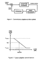
- FIG. 1 A block diagram representing a typical adaptive control system appears in Figure 1 .
- Set point power is the main command input, which is compared with power measured from the process. The difference between command and feedback power is calculated, filtered if necessary, and fed into the adaptive control block.
- the output of the adaptive control system is a feed rate override value, which is used to modify machining feed rates of the part program in real time, such that the actual machining process power is regulated as closely as possible to the programmed set point.
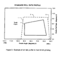
- FIG. 2 shows a simplified adaptive control function, which could be implemented within the "adaptive control" block of Figure 1 .
- This function would be applied for at least one tool or operation of a machining cycle.
- bulk power measured by the system is indicated along the horizontal axis.
- the feed rate override output is given along the vertical axis.
- P 0 the feed rate override value is 100%.
- the process power becomes larger, for example due to hard spot in workpiece material or decreasing tool sharpness, the system reduces the feed rate. As the measured power gets smaller, the system increases the override percentage.
- the adaptive control function shown in Figure 2 is linear, but does not have to be. Typical adaptive control systems allow the user to specify upper and lower feed rate override limits, as shown in the diagram.
- Adaptive control has not seen wide acceptance in gear manufacturing processes such as bevel gear grinding, bevel gear cutting, and stick blade grinding.
- the primary reason is that the degree of tool engagement in the workpiece varies continuously in bevel gear manufacturing processes. Controlling bulk power to a constant level would create drastically changing load per grit in the grinding wheel (or load per unit cutting edge length in the cutting tool), whereas process optimization seeks to find the highest constant load per grit (or per unit cutting edge length in a cutting tool). Therefore to be effective, an adaptive control system which measures tool spindle power would additionally require knowledge of tool engagement.
- known adaptive control systems are not capable of directly measuring and processing this additional information, and so are not able to provide the normally expected benefits in bevel applications.
- simulation software systems which optimize the tool path in an attempt to stabilize tool load.
- Such systems have knowledge of the tool engagement in the workpiece, so tool path (depth and angle of cutting) as well as feed rate adjustments can be made in the machining part program to maintain constant load.
- a limitation of such simulation systems is that they do not work in real time, and thus cannot compensate for typical manufacturing environment variation, such as tool wear, material and geometry variation of tool or workpiece, and machine setup changes due to human variation.
- known simulation systems are only capable of optimizing tool path for processes that use tools with defined cutting edges, i.e. the software lacks capability to deal with material removal processes with undefined tool edges, such as grinding.
- US-3,653,855 discloses a method for removing stock defining a target specific grinding energy.
- the present invention is directed to determining a desired power level as a function of relative tool to workpiece position, thereby enabling adaptive control advantages that were previously inaccessible for machining such as bevel gear grinding from solid applications.
- set point power is expressed as a function of specific power and roll position for a generated gear or as a function of specific power and plunge position for a non-generated (i.e. Formate) gear.
- Specific power is defined and preferably remains as defined during machining even as process conditions vary during machining.
- Bevel gears are usually manufactured by non-generating and/or generating machining processes performed on computer controlled machines such as those disclosed in US 6,669,415 or US 6,712,566 .
- a non-generating process utilizing a circular face milling cutting tool or a cup-shaped grinding wheel, for example
- tooth slots are formed by feeding a rotating tool into a workpiece to a predetermined depth, withdrawing the tool, and indexing the workpiece to another (usually the next) tooth slot position. The steps of feeding, withdrawing and indexing are repeated until all tooth slots are formed.
- the profile shape of a tooth on a workpiece is produced directly from the profile shape on the tool.
- a generating process may be performed wherein once the tool (e.g. circular face milling tool or cup-shaped grinding wheel) is fed to a predetermined depth, the tool and workpiece are then rolled together in a predetermined relative rolling motion, known as the generating roll or the cradle roll, as though the workpiece were rotating in mesh with a theoretical generating gear, the teeth of the theoretical generating gear being represented by the stock removing surfaces of the tool.
- the profile shape of the tooth is formed by relative motion of the tool and workpiece during the generating roll.
- the steps of feeding, rolling, withdrawing and indexing are repeated for each tooth slot until all tooth slots are formed.
- Tool engagement in this context means the fraction of tool cross-sectional profile engaged with the workpiece, as well as the length of tool-workpiece contact in the direction of tool rotation. For this reason it is difficult to set process conditions to get the most aggressive material removal possible without causing tool wear, burning, or other problems.
- State of the art grind-from-solid cycles for generated gears are typically arranged in two or three rotations, where in each rotation, the slots are ground with a non-standard cradle roll rate vs. cradle roll position profile.
- the feed rate profile usually involves several ramp segments. The feed rate profile is generally different for each rotation.
- a "rotation" of a work piece is achieved when a specified amount of stock material has been removed from each tooth slot.
- a first rotation of grinding may remove 80% of the desired stock material from each tooth slot while a subsequent second rotation of grinding may remove the remaining 20% of the desired stock material from each tooth slot.
- a three-rotation grinding cycle may, for example, remove stock material from all tooth slots in respective successive amounts of 60%, 30% and 10%.
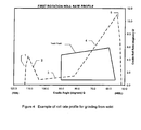
- the dotted line of Figure 3 shows an example of a typical feed rate profile that would be appropriate for hard-finishing a generated gear. Acceleration and deceleration sections, denoted (1) and (3), should not occur during actual machining. While the grinding wheel is in contact with the workpiece, the cradle roll rate profile is a constant function, section (2). A representative tooth flank is also drawn in Figure 3 to show the relationship of cradle roll position to the tooth flank.
- Figure 4 shows an example of a typical roll rate profile for one rotation of a grind-from-solid cycle for the same gear as in Figure 3 . Due to the absence of a semi-finished slot in the grinding-from-solid case (at least the first rotation), additional cradle roll travel is required since tool-workpiece contacts occurs earlier in a grind-from-solid process due to the absence of the semi-finished tooth slot. This explains why there is approximately 20° more toe end roll for the grinding from solid example ( Figure 4 ) versus the hard-finishing example ( Figure 3 ). Acceleration and deceleration sections are denoted (1) and (5), respectively. Material is machined to form the bevel gear slot in sections (2) - (4). These sections are ramped in such a manner as to create reasonably constant load per grit of the grinding wheel.
- the present invention is directed to determining the desired power level as a function of relative tool to workpiece position, thereby enabling adaptive control advantages that were previously inaccessible for machining such as bevel gear grinding-from-solid applications.
- set point power is expressed as a function of roll position for a generated gear or as a function of plunge position for a non-generated (i.e. Formate) gear.
- This function may be used in conjunction with adaptive control systems such that a conventional grinding-from-solid process may be enhanced to provide among other things:
- the degree of tool engagement in the workpiece changes as the slot is machined.
- the engagement changes can be quantified in terms of contact width changes, where contact width is defined as the effective width of the tool cross section in contact with the bevel gear slot surfaces at a given point in time.
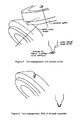
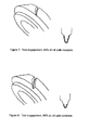
- Figures 5 - 8 show tool engagement variation in a typical grind from solid scenario as the tooth slot is ground from the toe end of the tooth slot to the heel end of the tooth slot.
- the cup-shaped wheel position near the beginning of the machine cradle roll motion is shown relative to the workpiece in Figure 5 .
- the wheel is not shown in successive roll positions of Figures 6 - 8 .
- a cross-sectional view of the tool profile is depicted showing the effective portion of tool profile engaged with the workpiece at that moment in time.
- the length of tool profile engagement in the cross section view is considered the contact width.
- the contact width can be calculated as a function of relative tool to workpiece position.
- such a function may be derived by the same or similar programs that calculate the bevel gear machine settings, such programs being known to the skilled artisan and readily available.
- a primary objective of the invention is to determine adaptive control set point power as a function of relative tool to workpiece position, such that the normalized load on the tool can be maintained at a constant, maximum level. Another objective is to provide a method which allows reliable grinding process enhancement without depending on a complicated, multi-variable process model. To achieve these objectives, the present invention prefers to take advantage of specific power, which is a grinding characteristic often used to evaluate grinding process health or to optimize the process.
- P' Specific power
- P f 2 P ⁇ W
- Figure 9 illustrates how this function may be coupled with an adaptive control system to provide an effective solution for grinding from solid.
- Figure 10 shows how a target specific power value may be selected for the grinding from solid process.
- specific power values P' 0 , P' 1 . P' 2 are shown versus specific metal removal rate, Z', in conjunction with characterization curves (A, B, C) representing different process conditions (e.g. grinding wheel, wheel speed, dressing parameters, tool-workpiece contact length, tool-workpiece contact width, tool-workpiece contact area, equivalent chip thickness, other tool-workpiece contact conditions, coolant application conditions, etc.), such process conditions being evident to the skilled artisan.
- process conditions e.g. grinding wheel, wheel speed, dressing parameters, tool-workpiece contact length, tool-workpiece contact width, tool-workpiece contact area, equivalent chip thickness, other tool-workpiece contact conditions, coolant application conditions, etc.
- P' 0 represents a specific target value P' for maintaining a robust grinding-from-solid process while the area above specific power level P' 1 signifies excessive wheel wear and the area above specific power level P' 2 is indicative of thermal damage to the grinding wheel and/or the part being ground. It can be seen that as process conditions change (i.e. from A to B to C), the specific metal removal rate, Z', can increase while maintaining the desired specific power value P' 0 .
- Figure 11 shows an example of the contact width function calculated for a specific gear.
- Figure 12 illustrates an example of a resultant power function that may be used to feed an adaptive control.
- Figure 12 also illustrates an example of an actual power curve resulting from the inventive method.
- the specific power metric may alternatively be normalized by contact area.
- the area normalized specific power metric is denoted P"
- the area A is denoted P
- the power function is determined in a manner analogous to the previously discussed power function determined in accordance with contact width.
- the area normalized power metric includes consideration of effective contact length and therefore may offer advantages for some applications.
- the foregoing description of the present invention suggests an approach whereby a single P' or P" value is selected for use in the power calculation function. Although this might be practical and sufficient in many applications, the invention also includes the possibility to vary the target specific power over the tool path. This may have advantages, for instance in difficult generated gear grinding cases where the effectiveness of the coolant application differs significantly as a function of generating roll position.
- plunge rates and plunge depth position replace cradle roll rate and roll position (cradle angle) in the form grinding case (see Figures 3-4 and 11-12 ).
- plunge velocity profiles have different shapes than corresponding roll rate profiles for hard-finish and grinding from solid cases, the same principles of varying process conditions apply.
- the preferred application of the present invention is grinding of bevel gears from solid.
- bevel gears is understood to include all of the known types of pinions and gears which transmit rotation energy across non-parallel shafts, including spiral bevel, hypoid, zero angle spiral bevel (e.g. Zerol) and straight bevel designs.
- Grinding from the solid refers to the process whereby entire slots are formed in a soft gear blank via grinding. Grinding from the solid is performed most commonly as a semi-finishing process prior to heat treatment. In cases involving small batch sizes, or where cutting tools and/or cutting machine is not readily available, grinding from solid can be more economical than the conventional cutting process.
- grinding from the solid i.e. a gear blank
- grinding pre-slotted, hardened gears is also contemplated by the present invention.
- the invention is applicable to other gear related processes, such as cutting blades and cutting blade blanks (e.g. stick blade grinding) and bevel gear cutting.
Landscapes
- Engineering & Computer Science (AREA)
- Mechanical Engineering (AREA)
- Physics & Mathematics (AREA)
- Manufacturing & Machinery (AREA)
- General Physics & Mathematics (AREA)
- Automation & Control Theory (AREA)
- Human Computer Interaction (AREA)
- Gear Processing (AREA)
- Automatic Control Of Machine Tools (AREA)
- Constituent Portions Of Griding Lathes, Driving, Sensing And Control (AREA)
- Turning (AREA)
- Gears, Cams (AREA)
- Grinding-Machine Dressing And Accessory Apparatuses (AREA)
Claims (11)
- Verfahren zum Entfernen von Material von einem Werkstück durch Bearbeiten mit einem Werkzeug, das Verfahren umfassend:Definieren einer zielspezifischen Kraft für das Verfahren, wobei die zielspezifische Kraft definiert wird als die Kraft, die entweder von der Kontaktbreite zwischen dem Werkzeug und dem Werkstück oder durch den Kontaktbereich zwischen dem Werkzeug und dem Werkstück normalisiert wird;Zusammenwirken des Werkstücks und des Werkzeugs;Entfernen von Material von dem Werkstück, wobei die Kraft während des Bearbeitens auf einen Kraftniveau eingestellt ist, das definiert ist als eine Funktion der relativen Werkzeug-zu-Werkstück-Position und der zielspezifischen Kraft, wobei die spezifische Kraft während des Bearbeitens im Wesentlichen als die zielspezifische Kraft verbleibt, obwohl die Bedingungen des Bearbeitungsprozesses, inklusive der Bedingungen des Werkzeugzusammenwirkens, während des Bearbeitungsprozesses variieren können.
- Verfahren gemäß Anspruch 1, wobei es sich bei einer der variablen Bedingungen des Bearbeitungsprozesses um die Kontaktbreite zwischen dem Werkzeug und dem Werkstück handelt.
- Verfahren gemäß Anspruch 1 oder 2, wobei es sich bei einer der variablen Bedingungen des Bearbeitungsprozesses um den Kontaktbereich zwischen dem Werkzeug und dem Werkstück handelt.
- Verfahren gemäß einem der Ansprüche 1 bis 3, wobei das Werkstück einen Zahnradrohling oder ein vorgeschlitztes Zahnrad umfasst.
- Verfahren gemäß einem der Ansprüche 1 bis 4, wobei es sich bei dem Bearbeitungsverfahren um ein Erzeugungsverfahren handelt.
- Verfahren gemäß einem der Ansprüche 1 bis 5, wobei es sich bei dem Bearbeitungsverfahren um ein Nicht-Erzeugungsverfahren handelt.
- Verfahren gemäß einem der Ansprüche 1 bis 6, wobei das Bearbeitungsverfahren einen Schleifvorgang umfasst.
- Verfahren gemäß einem der Ansprüche 1 bis 6, wobei das Bearbeitungsverfahren einen Schneidvorgang umfasst.
- Verfahren gemäß einem der Ansprüche 1 bis 8, wobei die zielspezifische Kraft während des Bearbeitungsverfahrens gleichbleibend ist.
- Verfahren gemäß einem der Ansprüche 1 bis 8, wobei die zielspezifische Kraft während des Bearbeitungsverfahrens variabel ist.
- Verfahren gemäß einem der Ansprüche 1 bis 10, wobei das Werkstück eine Schneidklinge oder einen Schneidklingenrohling umfasst.
Applications Claiming Priority (2)
| Application Number | Priority Date | Filing Date | Title |
|---|---|---|---|
| US35163510P | 2010-06-04 | 2010-06-04 | |
| PCT/US2011/039211 WO2011153520A1 (en) | 2010-06-04 | 2011-06-06 | Adaptive control of a machining process |
Publications (2)
| Publication Number | Publication Date |
|---|---|
| EP2576136A1 EP2576136A1 (de) | 2013-04-10 |
| EP2576136B1 true EP2576136B1 (de) | 2015-09-02 |
Family
ID=44453943
Family Applications (1)
| Application Number | Title | Priority Date | Filing Date |
|---|---|---|---|
| EP11725594.3A Active EP2576136B1 (de) | 2010-06-04 | 2011-06-06 | Adaptive steuerung eines bearbeitungsprozesses |
Country Status (8)
| Country | Link |
|---|---|
| US (1) | US8660684B2 (de) |
| EP (1) | EP2576136B1 (de) |
| JP (1) | JP5907956B2 (de) |
| KR (1) | KR20130069643A (de) |
| CN (1) | CN102905847B (de) |
| BR (1) | BR112012030887A2 (de) |
| MX (1) | MX340200B (de) |
| WO (1) | WO2011153520A1 (de) |
Families Citing this family (16)
| Publication number | Priority date | Publication date | Assignee | Title |
|---|---|---|---|---|
| CN103732340B (zh) * | 2011-07-29 | 2017-02-15 | 格里森工场 | 螺旋锥齿轮和准双曲面齿轮的顶锥元素的优化 |
| DE102015008956A1 (de) * | 2015-07-10 | 2017-01-12 | Liebherr-Verzahntechnik Gmbh | Verfahren zur Herstellung eines verzahnten Werkstückes mit modifizierter Oberflächengeometrie |
| DE102015009017A1 (de) * | 2015-07-10 | 2017-01-12 | Liebherr-Verzahntechnik Gmbh | Verfahren zur Herstellung eines verzahnten Werkstückes mit modifizierter Oberflächengeometrie |
| CN105279338B (zh) * | 2015-11-09 | 2018-04-03 | 中国电子科技集团公司第三十八研究所 | 一种面向组件加工的工艺模型构建方法 |
| CN105234429B (zh) * | 2015-11-10 | 2018-02-09 | 天津津航技术物理研究所 | 一种等刀纹间距恒线速度单点金刚石车削方法 |
| CN106897501B (zh) * | 2017-01-23 | 2019-07-05 | 西北工业大学 | 面向自适应加工中基于叶片类零件变形的定位优化方法 |
| JP6457563B2 (ja) * | 2017-01-24 | 2019-01-23 | ファナック株式会社 | 数値制御装置及び機械学習装置 |
| JP6557285B2 (ja) * | 2017-05-26 | 2019-08-07 | ファナック株式会社 | 制御装置及び機械学習装置 |
| WO2020205674A1 (en) | 2019-03-29 | 2020-10-08 | Saint-Gobain Abrasives, Inc. | Performance grinding solutions |
| US12226876B2 (en) | 2019-04-03 | 2025-02-18 | Saint-Gobain Abrasives, Inc. | Abrasive article, abrasive system and method for using and forming same |
| USD910830S1 (en) | 2019-04-12 | 2021-02-16 | Saint-Gobain Ceramics & Plastics, Inc. | Flame diffuser insert for immersion tube furnace |
| USD910829S1 (en) | 2019-04-12 | 2021-02-16 | Saint-Gobain Ceramics & Plastics, Inc. | Flame diffuser insert for immersion tube furnace |
| CH716583A1 (de) * | 2019-09-13 | 2021-03-15 | Reishauer Ag | Verfahren zur Überwachung eines Bearbeitungsprozesses, bei dem Zahnflanken vorverzahnter Werkstücke mit einer Feinbearbeitungsmaschine bearbeitet werden. |
| DE102020115463A1 (de) * | 2020-06-10 | 2021-12-16 | Homag Plattenaufteiltechnik Gmbh | Verfahren zum Betreiben einer Werkstückbearbeitungsanlage, sowie der Werkstückbearbeitungsanlage |
| CH721080B1 (de) | 2024-02-26 | 2025-03-14 | Reishauer Ag | Verfahren zur Bearbeitung von vorverzahnten Werkstücken durch kontinuierliches Wälzschleifen und entsprechende Verzahnmaschine |
| CN118915627A (zh) * | 2024-07-19 | 2024-11-08 | 大连理工大学 | 基于focas协议的机床外置式进给速度自适应控制方法 |
Citations (2)
| Publication number | Priority date | Publication date | Assignee | Title |
|---|---|---|---|---|
| US3653855A (en) * | 1969-05-23 | 1972-04-04 | Smith Roderick | Grinding system |
| WO2001030534A2 (en) * | 1999-10-27 | 2001-05-03 | Unova U.K. Limited | Constant spindle power grinding method |
Family Cites Families (18)
| Publication number | Priority date | Publication date | Assignee | Title |
|---|---|---|---|---|
| GB1349563A (en) * | 1971-03-01 | 1974-04-03 | Werkzeugmasch Okt Veb | Control systems for gear cutting machines |
| CH574296A5 (en) * | 1973-09-21 | 1976-04-15 | Perm Polt I | Control of tooth flank roller grinding machine - has store between subtractor and comparator to store highest pulse of cutting output |
| DE2351592A1 (de) * | 1973-10-13 | 1975-05-22 | Perm Politekhn I Udssr | Einrichtung zur steuerung einer zahnflankenschleifmaschine |
| US4137677A (en) * | 1977-10-03 | 1979-02-06 | General Electric Company | Constant horsepower control for grinding wheel drives |
| US4523409A (en) * | 1983-05-19 | 1985-06-18 | The Charles Stark Draper Laboratory, Inc. | Automatic contour grinding system |
| JPS6056821A (ja) * | 1983-09-09 | 1985-04-02 | Honda Motor Co Ltd | 歯車研削機 |
| CH663891A5 (de) * | 1984-10-24 | 1988-01-29 | Marco Dr Sc Techn Brandestini | Vorrichtung fuer die formgebende bearbeitung eines rohlings aus dentalkeramischem oder dentalem komposit-material und verfahren zu deren betrieb. |
| TW405470U (en) * | 1993-01-22 | 2000-09-11 | Toyota Motor Co Ltd | Apparatus for machining and measuring a gear shape |
| JP3362952B2 (ja) * | 1993-11-01 | 2003-01-07 | トーヨーエイテック株式会社 | 適応制御研削方法及びその装置 |
| AU3106899A (en) * | 1998-03-18 | 1999-10-11 | Gleason Works, The | Threaded grinding wheel and method of dressing |
| US6669415B2 (en) | 2001-02-16 | 2003-12-30 | The Gleason Works | Machine for producing bevel gears |
| JP2003048124A (ja) * | 2001-08-07 | 2003-02-18 | Kanzaki Kokyukoki Mfg Co Ltd | 金型又は放電加工用電極の製造方法 |
| CN1628011B (zh) * | 2002-02-07 | 2010-09-29 | 格里森工场 | 磨削切削刀片的方法 |
| JP2003291064A (ja) * | 2002-03-29 | 2003-10-14 | Toyo Advanced Technologies Co Ltd | 研削加工方法及び装置 |
| JP2004089773A (ja) * | 2002-08-29 | 2004-03-25 | Sumitomo Heavy Ind Ltd | 廃棄物処理設備 |
| EP1578562B1 (de) * | 2003-01-02 | 2007-02-14 | Cinetic Landis Grinding Limited | Schleifscheiben-überwachung |
| US20060074512A1 (en) * | 2004-09-29 | 2006-04-06 | One World Technologies Limited | Feed rate controller |
| US7527548B2 (en) * | 2005-03-10 | 2009-05-05 | Sikorsky Aircraft Corporation | System and method for precision machining of high hardness gear teeth and splines |
-
2011
- 2011-06-06 EP EP11725594.3A patent/EP2576136B1/de active Active
- 2011-06-06 JP JP2013513406A patent/JP5907956B2/ja active Active
- 2011-06-06 US US13/153,539 patent/US8660684B2/en active Active
- 2011-06-06 KR KR1020127030771A patent/KR20130069643A/ko not_active Ceased
- 2011-06-06 WO PCT/US2011/039211 patent/WO2011153520A1/en not_active Ceased
- 2011-06-06 BR BR112012030887A patent/BR112012030887A2/pt not_active Application Discontinuation
- 2011-06-06 CN CN201180026197.0A patent/CN102905847B/zh active Active
- 2011-06-06 MX MX2012013949A patent/MX340200B/es active IP Right Grant
Patent Citations (2)
| Publication number | Priority date | Publication date | Assignee | Title |
|---|---|---|---|---|
| US3653855A (en) * | 1969-05-23 | 1972-04-04 | Smith Roderick | Grinding system |
| WO2001030534A2 (en) * | 1999-10-27 | 2001-05-03 | Unova U.K. Limited | Constant spindle power grinding method |
Also Published As
| Publication number | Publication date |
|---|---|
| JP5907956B2 (ja) | 2016-04-26 |
| MX340200B (es) | 2016-06-30 |
| BR112012030887A2 (pt) | 2016-11-08 |
| EP2576136A1 (de) | 2013-04-10 |
| CN102905847B (zh) | 2016-06-01 |
| KR20130069643A (ko) | 2013-06-26 |
| US8660684B2 (en) | 2014-02-25 |
| WO2011153520A1 (en) | 2011-12-08 |
| CN102905847A (zh) | 2013-01-30 |
| MX2012013949A (es) | 2013-02-11 |
| US20110301742A1 (en) | 2011-12-08 |
| JP2013527044A (ja) | 2013-06-27 |
Similar Documents
| Publication | Publication Date | Title |
|---|---|---|
| EP2576136B1 (de) | Adaptive steuerung eines bearbeitungsprozesses | |
| US10293453B2 (en) | Method of grinding a workpiece and method for determining processing parameters | |
| CN107335868B (zh) | 用于对工件进行齿加工的方法 | |
| JP6095259B2 (ja) | 歯車の歯を加工するための方法、歯車の歯を有するワーク、及び工作機械 | |
| US11358233B2 (en) | Method for generating a toothed workpiece and control program, tools and tooth-cutting machine suitable therefor | |
| JP2018116707A5 (de) | ||
| US10710183B2 (en) | Method for determining the flank face contour of a gear skiving tool, gear skiving tool and use thereof | |
| TWI572432B (zh) | 製造齒輪嚙合之方法、銑齒機及控制銑齒機用的電腦程式產品 | |
| CA2808938C (en) | Method for machining a workpiece | |
| JPH0215963A (ja) | カム軸のカムを研削する方法 | |
| JP2020504023A (ja) | 歯付き歯車、特に内歯部分を硬仕上げするための方法およびそれに好適な機械工具 | |
| CN102303127A (zh) | 数控车床车削去除不完整螺纹的方法 | |
| CN105562796A (zh) | 窄深槽台阶式分层铣削法 | |
| CN105689807A (zh) | 具有多个切削策略的强力刮削加工方法 | |
| RU2429949C1 (ru) | Способ обработки моноколес | |
| CN110877132B (zh) | 用于工件的齿轮制造加工的方法 | |
| US20200246890A1 (en) | Method for machining gear wheel workpieces | |
| CN103167924A (zh) | 齿轮加工装置及齿轮加工条件设定装置 | |
| CN214053816U (zh) | 一种便于控制刃宽的刀具 | |
| Rowe et al. | Towards an adaptive strategy for dressing in grinding operations | |
| RU2038943C1 (ru) | Способ управления циклом шлифования на многоинструментальном станке | |
| CN117464099A (zh) | 一种起重机用矩形螺纹加工刀具移动坐标确定方法 | |
| Shan | Application of dynamic milling in stainless steel processing | |
| WINKEL | MODERN SOLUTIONS FOR CHAMFERING OF GEARS |
Legal Events
| Date | Code | Title | Description |
|---|---|---|---|
| PUAI | Public reference made under article 153(3) epc to a published international application that has entered the european phase |
Free format text: ORIGINAL CODE: 0009012 |
|
| 17P | Request for examination filed |
Effective date: 20121112 |
|
| AK | Designated contracting states |
Kind code of ref document: A1 Designated state(s): AL AT BE BG CH CY CZ DE DK EE ES FI FR GB GR HR HU IE IS IT LI LT LU LV MC MK MT NL NO PL PT RO RS SE SI SK SM TR |
|
| DAX | Request for extension of the european patent (deleted) | ||
| 17Q | First examination report despatched |
Effective date: 20131017 |
|
| GRAP | Despatch of communication of intention to grant a patent |
Free format text: ORIGINAL CODE: EPIDOSNIGR1 |
|
| INTG | Intention to grant announced |
Effective date: 20150612 |
|
| GRAS | Grant fee paid |
Free format text: ORIGINAL CODE: EPIDOSNIGR3 |
|
| GRAA | (expected) grant |
Free format text: ORIGINAL CODE: 0009210 |
|
| AK | Designated contracting states |
Kind code of ref document: B1 Designated state(s): AL AT BE BG CH CY CZ DE DK EE ES FI FR GB GR HR HU IE IS IT LI LT LU LV MC MK MT NL NO PL PT RO RS SE SI SK SM TR |
|
| REG | Reference to a national code |
Ref country code: GB Ref legal event code: FG4D |
|
| REG | Reference to a national code |
Ref country code: AT Ref legal event code: REF Ref document number: 746244 Country of ref document: AT Kind code of ref document: T Effective date: 20150915 Ref country code: CH Ref legal event code: EP |
|
| REG | Reference to a national code |
Ref country code: IE Ref legal event code: FG4D |
|
| REG | Reference to a national code |
Ref country code: CH Ref legal event code: NV Representative=s name: WERNER FENNER PATENTANWALT, CH |
|
| REG | Reference to a national code |
Ref country code: DE Ref legal event code: R096 Ref document number: 602011019364 Country of ref document: DE |
|
| REG | Reference to a national code |
Ref country code: AT Ref legal event code: MK05 Ref document number: 746244 Country of ref document: AT Kind code of ref document: T Effective date: 20150902 |
|
| PG25 | Lapsed in a contracting state [announced via postgrant information from national office to epo] |
Ref country code: LV Free format text: LAPSE BECAUSE OF FAILURE TO SUBMIT A TRANSLATION OF THE DESCRIPTION OR TO PAY THE FEE WITHIN THE PRESCRIBED TIME-LIMIT Effective date: 20150902 Ref country code: GR Free format text: LAPSE BECAUSE OF FAILURE TO SUBMIT A TRANSLATION OF THE DESCRIPTION OR TO PAY THE FEE WITHIN THE PRESCRIBED TIME-LIMIT Effective date: 20151203 Ref country code: NO Free format text: LAPSE BECAUSE OF FAILURE TO SUBMIT A TRANSLATION OF THE DESCRIPTION OR TO PAY THE FEE WITHIN THE PRESCRIBED TIME-LIMIT Effective date: 20151202 Ref country code: FI Free format text: LAPSE BECAUSE OF FAILURE TO SUBMIT A TRANSLATION OF THE DESCRIPTION OR TO PAY THE FEE WITHIN THE PRESCRIBED TIME-LIMIT Effective date: 20150902 Ref country code: LT Free format text: LAPSE BECAUSE OF FAILURE TO SUBMIT A TRANSLATION OF THE DESCRIPTION OR TO PAY THE FEE WITHIN THE PRESCRIBED TIME-LIMIT Effective date: 20150902 |
|
| REG | Reference to a national code |
Ref country code: LT Ref legal event code: MG4D Ref country code: NL Ref legal event code: MP Effective date: 20150902 |
|
| PG25 | Lapsed in a contracting state [announced via postgrant information from national office to epo] |
Ref country code: AT Free format text: LAPSE BECAUSE OF FAILURE TO SUBMIT A TRANSLATION OF THE DESCRIPTION OR TO PAY THE FEE WITHIN THE PRESCRIBED TIME-LIMIT Effective date: 20150902 Ref country code: PL Free format text: LAPSE BECAUSE OF FAILURE TO SUBMIT A TRANSLATION OF THE DESCRIPTION OR TO PAY THE FEE WITHIN THE PRESCRIBED TIME-LIMIT Effective date: 20150902 Ref country code: RS Free format text: LAPSE BECAUSE OF FAILURE TO SUBMIT A TRANSLATION OF THE DESCRIPTION OR TO PAY THE FEE WITHIN THE PRESCRIBED TIME-LIMIT Effective date: 20150902 Ref country code: ES Free format text: LAPSE BECAUSE OF FAILURE TO SUBMIT A TRANSLATION OF THE DESCRIPTION OR TO PAY THE FEE WITHIN THE PRESCRIBED TIME-LIMIT Effective date: 20150902 Ref country code: SE Free format text: LAPSE BECAUSE OF FAILURE TO SUBMIT A TRANSLATION OF THE DESCRIPTION OR TO PAY THE FEE WITHIN THE PRESCRIBED TIME-LIMIT Effective date: 20150902 |
|
| PG25 | Lapsed in a contracting state [announced via postgrant information from national office to epo] |
Ref country code: NL Free format text: LAPSE BECAUSE OF FAILURE TO SUBMIT A TRANSLATION OF THE DESCRIPTION OR TO PAY THE FEE WITHIN THE PRESCRIBED TIME-LIMIT Effective date: 20150902 Ref country code: EE Free format text: LAPSE BECAUSE OF FAILURE TO SUBMIT A TRANSLATION OF THE DESCRIPTION OR TO PAY THE FEE WITHIN THE PRESCRIBED TIME-LIMIT Effective date: 20150902 Ref country code: IS Free format text: LAPSE BECAUSE OF FAILURE TO SUBMIT A TRANSLATION OF THE DESCRIPTION OR TO PAY THE FEE WITHIN THE PRESCRIBED TIME-LIMIT Effective date: 20160102 Ref country code: IT Free format text: LAPSE BECAUSE OF FAILURE TO SUBMIT A TRANSLATION OF THE DESCRIPTION OR TO PAY THE FEE WITHIN THE PRESCRIBED TIME-LIMIT Effective date: 20150902 Ref country code: CZ Free format text: LAPSE BECAUSE OF FAILURE TO SUBMIT A TRANSLATION OF THE DESCRIPTION OR TO PAY THE FEE WITHIN THE PRESCRIBED TIME-LIMIT Effective date: 20150902 Ref country code: SK Free format text: LAPSE BECAUSE OF FAILURE TO SUBMIT A TRANSLATION OF THE DESCRIPTION OR TO PAY THE FEE WITHIN THE PRESCRIBED TIME-LIMIT Effective date: 20150902 |
|
| PG25 | Lapsed in a contracting state [announced via postgrant information from national office to epo] |
Ref country code: PT Free format text: LAPSE BECAUSE OF FAILURE TO SUBMIT A TRANSLATION OF THE DESCRIPTION OR TO PAY THE FEE WITHIN THE PRESCRIBED TIME-LIMIT Effective date: 20160104 Ref country code: RO Free format text: LAPSE BECAUSE OF FAILURE TO SUBMIT A TRANSLATION OF THE DESCRIPTION OR TO PAY THE FEE WITHIN THE PRESCRIBED TIME-LIMIT Effective date: 20150902 |
|
| REG | Reference to a national code |
Ref country code: DE Ref legal event code: R097 Ref document number: 602011019364 Country of ref document: DE |
|
| PLBE | No opposition filed within time limit |
Free format text: ORIGINAL CODE: 0009261 |
|
| STAA | Information on the status of an ep patent application or granted ep patent |
Free format text: STATUS: NO OPPOSITION FILED WITHIN TIME LIMIT |
|
| 26N | No opposition filed |
Effective date: 20160603 |
|
| PG25 | Lapsed in a contracting state [announced via postgrant information from national office to epo] |
Ref country code: SI Free format text: LAPSE BECAUSE OF FAILURE TO SUBMIT A TRANSLATION OF THE DESCRIPTION OR TO PAY THE FEE WITHIN THE PRESCRIBED TIME-LIMIT Effective date: 20150902 Ref country code: DK Free format text: LAPSE BECAUSE OF FAILURE TO SUBMIT A TRANSLATION OF THE DESCRIPTION OR TO PAY THE FEE WITHIN THE PRESCRIBED TIME-LIMIT Effective date: 20150902 |
|
| PG25 | Lapsed in a contracting state [announced via postgrant information from national office to epo] |
Ref country code: BE Free format text: LAPSE BECAUSE OF FAILURE TO SUBMIT A TRANSLATION OF THE DESCRIPTION OR TO PAY THE FEE WITHIN THE PRESCRIBED TIME-LIMIT Effective date: 20150902 |
|
| PG25 | Lapsed in a contracting state [announced via postgrant information from national office to epo] |
Ref country code: MC Free format text: LAPSE BECAUSE OF FAILURE TO SUBMIT A TRANSLATION OF THE DESCRIPTION OR TO PAY THE FEE WITHIN THE PRESCRIBED TIME-LIMIT Effective date: 20150902 |
|
| GBPC | Gb: european patent ceased through non-payment of renewal fee |
Effective date: 20160606 |
|
| REG | Reference to a national code |
Ref country code: IE Ref legal event code: MM4A |
|
| REG | Reference to a national code |
Ref country code: FR Ref legal event code: ST Effective date: 20170228 |
|
| PG25 | Lapsed in a contracting state [announced via postgrant information from national office to epo] |
Ref country code: FR Free format text: LAPSE BECAUSE OF NON-PAYMENT OF DUE FEES Effective date: 20160630 |
|
| PG25 | Lapsed in a contracting state [announced via postgrant information from national office to epo] |
Ref country code: IE Free format text: LAPSE BECAUSE OF NON-PAYMENT OF DUE FEES Effective date: 20160606 Ref country code: GB Free format text: LAPSE BECAUSE OF NON-PAYMENT OF DUE FEES Effective date: 20160606 |
|
| PG25 | Lapsed in a contracting state [announced via postgrant information from national office to epo] |
Ref country code: HU Free format text: LAPSE BECAUSE OF FAILURE TO SUBMIT A TRANSLATION OF THE DESCRIPTION OR TO PAY THE FEE WITHIN THE PRESCRIBED TIME-LIMIT; INVALID AB INITIO Effective date: 20110606 Ref country code: SM Free format text: LAPSE BECAUSE OF FAILURE TO SUBMIT A TRANSLATION OF THE DESCRIPTION OR TO PAY THE FEE WITHIN THE PRESCRIBED TIME-LIMIT Effective date: 20150902 Ref country code: CY Free format text: LAPSE BECAUSE OF FAILURE TO SUBMIT A TRANSLATION OF THE DESCRIPTION OR TO PAY THE FEE WITHIN THE PRESCRIBED TIME-LIMIT Effective date: 20150902 |
|
| PG25 | Lapsed in a contracting state [announced via postgrant information from national office to epo] |
Ref country code: MT Free format text: LAPSE BECAUSE OF NON-PAYMENT OF DUE FEES Effective date: 20160630 Ref country code: LU Free format text: LAPSE BECAUSE OF NON-PAYMENT OF DUE FEES Effective date: 20160606 Ref country code: TR Free format text: LAPSE BECAUSE OF FAILURE TO SUBMIT A TRANSLATION OF THE DESCRIPTION OR TO PAY THE FEE WITHIN THE PRESCRIBED TIME-LIMIT Effective date: 20150902 Ref country code: MK Free format text: LAPSE BECAUSE OF FAILURE TO SUBMIT A TRANSLATION OF THE DESCRIPTION OR TO PAY THE FEE WITHIN THE PRESCRIBED TIME-LIMIT Effective date: 20150902 Ref country code: HR Free format text: LAPSE BECAUSE OF FAILURE TO SUBMIT A TRANSLATION OF THE DESCRIPTION OR TO PAY THE FEE WITHIN THE PRESCRIBED TIME-LIMIT Effective date: 20150902 |
|
| PG25 | Lapsed in a contracting state [announced via postgrant information from national office to epo] |
Ref country code: BG Free format text: LAPSE BECAUSE OF FAILURE TO SUBMIT A TRANSLATION OF THE DESCRIPTION OR TO PAY THE FEE WITHIN THE PRESCRIBED TIME-LIMIT Effective date: 20150902 |
|
| PG25 | Lapsed in a contracting state [announced via postgrant information from national office to epo] |
Ref country code: AL Free format text: LAPSE BECAUSE OF FAILURE TO SUBMIT A TRANSLATION OF THE DESCRIPTION OR TO PAY THE FEE WITHIN THE PRESCRIBED TIME-LIMIT Effective date: 20150902 |
|
| REG | Reference to a national code |
Ref country code: CH Ref legal event code: NV Representative=s name: SERAINA FENNER, CH |
|
| P01 | Opt-out of the competence of the unified patent court (upc) registered |
Effective date: 20230516 |
|
| PGFP | Annual fee paid to national office [announced via postgrant information from national office to epo] |
Ref country code: DE Payment date: 20250627 Year of fee payment: 15 |
|
| PGFP | Annual fee paid to national office [announced via postgrant information from national office to epo] |
Ref country code: CH Payment date: 20250701 Year of fee payment: 15 |