EP2575346A1 - Geräteausrichtungsabhängige Autofokusvorgänge - Google Patents
Geräteausrichtungsabhängige Autofokusvorgänge Download PDFInfo
- Publication number
- EP2575346A1 EP2575346A1 EP12186063A EP12186063A EP2575346A1 EP 2575346 A1 EP2575346 A1 EP 2575346A1 EP 12186063 A EP12186063 A EP 12186063A EP 12186063 A EP12186063 A EP 12186063A EP 2575346 A1 EP2575346 A1 EP 2575346A1
- Authority
- EP
- European Patent Office
- Prior art keywords
- autofocus
- image capture
- capture device
- digital image
- motion
- Prior art date
- Legal status (The legal status is an assumption and is not a legal conclusion. Google has not performed a legal analysis and makes no representation as to the accuracy of the status listed.)
- Withdrawn
Links
- 230000001419 dependent effect Effects 0.000 title 1
- 238000000034 method Methods 0.000 claims abstract description 25
- 238000012545 processing Methods 0.000 description 7
- 238000010586 diagram Methods 0.000 description 6
- 230000009286 beneficial effect Effects 0.000 description 3
- 238000004590 computer program Methods 0.000 description 3
- 238000011161 development Methods 0.000 description 3
- 230000001133 acceleration Effects 0.000 description 2
- 238000013461 design Methods 0.000 description 2
- 238000001514 detection method Methods 0.000 description 2
- 230000006870 function Effects 0.000 description 2
- 239000004065 semiconductor Substances 0.000 description 2
- 238000013459 approach Methods 0.000 description 1
- 230000000295 complement effect Effects 0.000 description 1
- 230000000694 effects Effects 0.000 description 1
- 239000000463 material Substances 0.000 description 1
- 229910044991 metal oxide Inorganic materials 0.000 description 1
- 150000004706 metal oxides Chemical class 0.000 description 1
- 230000003287 optical effect Effects 0.000 description 1
- 230000002250 progressing effect Effects 0.000 description 1
Images



Classifications
-
- H—ELECTRICITY
- H04—ELECTRIC COMMUNICATION TECHNIQUE
- H04N—PICTORIAL COMMUNICATION, e.g. TELEVISION
- H04N1/00—Scanning, transmission or reproduction of documents or the like, e.g. facsimile transmission; Details thereof
- H04N1/21—Intermediate information storage
- H04N1/2104—Intermediate information storage for one or a few pictures
- H04N1/2112—Intermediate information storage for one or a few pictures using still video cameras
-
- G—PHYSICS
- G03—PHOTOGRAPHY; CINEMATOGRAPHY; ANALOGOUS TECHNIQUES USING WAVES OTHER THAN OPTICAL WAVES; ELECTROGRAPHY; HOLOGRAPHY
- G03B—APPARATUS OR ARRANGEMENTS FOR TAKING PHOTOGRAPHS OR FOR PROJECTING OR VIEWING THEM; APPARATUS OR ARRANGEMENTS EMPLOYING ANALOGOUS TECHNIQUES USING WAVES OTHER THAN OPTICAL WAVES; ACCESSORIES THEREFOR
- G03B13/00—Viewfinders; Focusing aids for cameras; Means for focusing for cameras; Autofocus systems for cameras
- G03B13/32—Means for focusing
- G03B13/34—Power focusing
- G03B13/36—Autofocus systems
-
- H—ELECTRICITY
- H04—ELECTRIC COMMUNICATION TECHNIQUE
- H04N—PICTORIAL COMMUNICATION, e.g. TELEVISION
- H04N23/00—Cameras or camera modules comprising electronic image sensors; Control thereof
- H04N23/60—Control of cameras or camera modules
- H04N23/67—Focus control based on electronic image sensor signals
- H04N23/673—Focus control based on electronic image sensor signals based on contrast or high frequency components of image signals, e.g. hill climbing method
-
- H—ELECTRICITY
- H04—ELECTRIC COMMUNICATION TECHNIQUE
- H04N—PICTORIAL COMMUNICATION, e.g. TELEVISION
- H04N23/00—Cameras or camera modules comprising electronic image sensors; Control thereof
- H04N23/60—Control of cameras or camera modules
- H04N23/67—Focus control based on electronic image sensor signals
- H04N23/676—Bracketing for image capture at varying focusing conditions
-
- H—ELECTRICITY
- H04—ELECTRIC COMMUNICATION TECHNIQUE
- H04N—PICTORIAL COMMUNICATION, e.g. TELEVISION
- H04N2101/00—Still video cameras
-
- H—ELECTRICITY
- H04—ELECTRIC COMMUNICATION TECHNIQUE
- H04N—PICTORIAL COMMUNICATION, e.g. TELEVISION
- H04N2201/00—Indexing scheme relating to scanning, transmission or reproduction of documents or the like, and to details thereof
- H04N2201/0077—Types of the still picture apparatus
- H04N2201/0084—Digital still camera
-
- H—ELECTRICITY
- H04—ELECTRIC COMMUNICATION TECHNIQUE
- H04N—PICTORIAL COMMUNICATION, e.g. TELEVISION
- H04N2201/00—Indexing scheme relating to scanning, transmission or reproduction of documents or the like, and to details thereof
- H04N2201/0096—Portable devices
Definitions
- a camera's autofocus (AF) system automatically adjusts the camera lens to obtain focus on a subject.
- AF systems use contrast sensors within the camera (passive AF) or by emitting a signal to illuminate or estimate the distance to a subject (active AF).
- Passive AF may employ either contrast detection or phase detection methods, but both rely on contrast for achieving autofocus.
- Some digital cameras utilize autofocus sensors that are different from the camera's image sensor. This may, for example, occur in single-function digital cameras. In small multifunction devices such as mobile phones, tablet computers, personal digital assistants and portable music/video players, however, separate image and autofocus sensors are often not used. In devices such as these, autofocus operations can involve adjusting the position of the device's lens (or lens assembly) at a specified number of locations; evaluating the focus (e.g. , contrast) between corresponding points in successive images (maximum contrast is assumed to correspond to maximum sharpness or "best" focus).
- focus e.g. , contrast
- Multifunction devices typically evaluate contrast/focus at a fixed number of points in an image and, when the lens is moved to obtain successive images, a fixed number of lens positions. As such, these devices can provide autofocus operations at a fixed rate and with a fixed resolution. Thus, it would be beneficial to provide a mechanism to dynamically improve the speed or resolution of a digital image capture device.
- a method to perform an autofocus operation for a digital image capture device using knowledge of the device's orientation includes determining the orientation of the device based at least in part on the signal from an orientation sensor.
- One illustrative orientation sensor is an accelerometer.
- a range of motion may be determined for the autofocus operation. This range of motion refers to the distance through which a lens, or lens assembly, is moved during the autofocus operation.
- the device's orientation often causes this range to be less than the device's autofocus full range of motion ( i.e. , the maximum distance through which the lens may be moved during autofocus operations).
- the autofocus operation may be performed based on the autofocus range of motion and less than the device's full number of autofocus points-of-interest. If the autofocus mode is set to HIGH-RESOLUTION, the autofocus operation may be performed based on the autofocus range of motion and the device's full number of autofocus points-of-interest.
- the method may be embodied in computer executable program code and stored in a non-transitory storage device. In yet another embodiment, the method may be implemented in an electronic device having digital image capture capabilities.
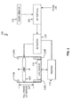
- Figure 1 shows, in block diagram form, a simplified block diagram of an autofocus system in accordance with one embodiment.
- Figure 2 shows three orientations for an image capture device at which orientation information may be obtained.
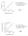
- Figure 3 shows the relationship between orientation sensor output and actuator input required to focus the image capture device at infinity in accordance with one embodiment.
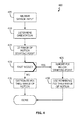
- Figure 4 shows, in flowchart form, an autofocus operation in accordance with one embodiment.
- Figure 5 shows the relationship between orientation sensor output and actuator input required to focus the image capture device at infinity in accordance with another embodiment.
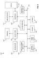
- Figure 6 shows, in block diagram form, a simplified multifunction device according to one embodiment.
- Figure 7 illustrates the idea of corresponding points in successive images in accordance with one embodiment.
- Figure 8 illustrates the idea of using regions for the comparison of successive images in accordance with one embodiment.
- orientation information such as that available from an accelerometer may be used to reduce the number of lens positions (points-of-interest, POI) used during an AF operation, thereby improving the operation's speed.
- orientation information may be used to reduce the lens' range of motion while maintaining the number of POI, thereby improving the operation's resolution.
- a simplified block diagram of AF system 100 in accordance with one embodiment includes lens 105, image sensor 110, memory 115 and mechanical stops 120 ( 120a, 120b, 120c and 120d) which define full range of motion 125. Also included are actuator 130 for displacing lens 105 between mechanical stops 120, orientation sensor 135 and mode select input 140, both of which supply input to AF control unit 145.
- an image capture device may use a charged coupled device (or a complementary metal-oxide semiconductor), an electromechanical unit (e.g. , a voice coil motor) as actuator 130 and an accelerometer as orientation sensor 135.It will be understood that accelerometers measure acceleration in the direction of the sensor's plane.
- AF system 100 may be configured such that when image capture device is in an up-facing orientation (e.g. , 200a ) accelerometer output corresponds to +1g, when in a horizontal-facing orientation ( e.g ., 200b ) accelerometer output corresponds to 0g and when in a down-facing orientation ( e.g ., 200c ) accelerometer output corresponds to -1g.
- a horizontal-facing orientation e.g ., 200b
- a down-facing orientation e.g ., 200c
- voice motor coil actuator 130 may be driven by a digital signal.
- the motion of lens 105 may be designated by a voice motor coil input signal between specified minimum and maximum values.
- FIG. 3 one relationship between accelerometer output and actuator input (e.g. , voice motor coil input) to focus the image capture device at infinity is shown.
- actuator input e.g. , voice motor coil input
- FIGS. 2 and 3 it can be seen that when the image capture device is in an up-facing orientation ( 200a ), voice motor coil actuator 130 must be driven with the maximum input signal (MAX) to place the lens such that focus is achieved at infinity.
- MAX maximum input signal
- MID maximum and minimum values
- voice motor coil actuator 130 when the image capture device is in a down-facing orientation (200c), voice motor coil actuator 130 must be driven with the minimum input signal (MIN) to place the lens such that focus is achieved at infinity.
- MIN minimum input signal
- orientation sensor 135 may be used to determine an image capture device's orientation and, based on this, provide a faster AF operation or a higher resolution AF operation.
- AF operation 400 begins when orientation sensor input is received at AF control unit 145 (block 405). From that input, the image capture device's orientation may be determined as described above (block 410). Using a knowledge of the relationship between the orientation sensor's output and the actuator's output needed to focus the image capture device at infinity (e.g. , as shown in FIG. 3 ), a starting point for AF operation 400 may be determined (block 415).
- orientation sensor 135 e.g. , an accelerometer
- AF control unit 145 with input representative of accelerations between -1g (down-facing) and +1g (up-facing) as illustrated in FIG. 2 ; that AF control unit 145 drives actuator 130 ( e.g. , a voice motor coil) with a signal having a minimum value 'A' and a maximum value 'G;' that AF operation 400 moves lens 105 from a focus point at infinity to the image capture device's closest focus point; and that when the lens' full range of motion 125 is used during AP operation 400, seven POI are used (identified by actuator inputs A, B, C, D, E, F, and G).
- the voice motor coil input 'Y' corresponds to the AF range of motion's starting point and the device's AF range of motion may be given by the range of actuator input voltages: Y to G.
- mode input 140 may then be used to determine whether the image capture device should operate in the FAST mode or the HIGH-RESOLUTION or FINE mode. If mode input 140 indicates the FAST mode (the "YES" prong of block 420), all specified POI below the lens position corresponding to value 'Y' would be ignored during the remainder of AF operation 400 (block 425). This results in AF operation 400 evaluating images for contrast at lens locations corresponding to actuator inputs of C, D, E, F and G (block 430). Thus, in FAST mode AF operation 400 evaluates images at only 5 locations rather than the specified 7 locations. It has been found this can provide a significant speed-up in AF operations.
- the specified number of locations (7) may be redistributed over the remaining range of motion: C through G (block 435).
- the number of lens positions at which to evaluate images may be fewer or more than seven (7).
- the positions may be distributed over the range of motion in any desired manner: uniformly as illustrated in FIG.
- Multifunction electronic device 600 may include processor 605, display 610, user interface 615, graphics hardware 620, device sensors 625 (e.g. , proximity sensor/ambient light sensor, accelerometer and/or gyroscope), microphone 630, audio codec(s) 635 , speaker(s) 640 , communications circuitry 645, digital image capture unit 650 ( e.g. , including autofocus unit 100 )video codec(s) 655 , memory 660, storage device 665, and communications bus 670.
- Multifunction electronic device 600 may be, for example, a digital camera or a personal electronic device such as a personal digital assistant (PDA), personal music player, mobile telephone, or a tablet computer.
- PDA personal digital assistant
- Processor 605 may execute instructions necessary to carry out or control the operation of many functions performed by device 600 (e.g. , such as the generation and/or processing of images).
- Processor 605 may, for instance, drive display 610 and receive user input from user interface 615.
- User interface 615 may allow a user to interact with device 600.
- user interface 615 can take a variety of forms, such as a button, keypad, dial, a click wheel, keyboard, display screen and/or a touch screen.
- Processor 605 may also, for example, be a system-on-chip such as those found in mobile devices and include a dedicated graphics processing unit (GPU).
- GPU dedicated graphics processing unit
- Processor 605 may be based on reduced instruction-set computer (RISC) or complex instruction-set computer (CISC) architectures or any other suitable architecture and may include one or more processing cores.
- Graphics hardware 620 may be special purpose computational hardware for processing graphics and/or assisting processor 605 to process graphics information.
- graphics hardware 620 may include a programmable graphics processing unit (GPU).
- Sensor and camera circuitry 650 may capture still and video images that may be processed, at least in part, by video codec(s) 655 and/or processor 605 and/or graphics hardware 620, and/or a dedicated image processing unit incorporated within circuitry 650. Images so captured may be stored in memory 660 and/or storage 665.
- Memory 660 may include one or more different types of media used by processor 605 and graphics hardware 620 to perform device functions.
- memory 660 may include memory cache, read-only memory (ROM), and/or random access memory (RAM).
- Storage 665 may store media (e.g. , audio, image and video files), computer program instructions or software, preference information, device profile information, and any other suitable data.
- Storage 665 may include one more non-transitory storage mediums including, for example, magnetic disks (fixed, floppy, and removable) and tape, optical media such as CD-ROMs and digital video disks (DVDs), and semiconductor memory devices such as Electrically Programmable Read-Only Memory (EPROM), and Electrically Erasable Programmable Read-Only Memory (EEPROM).
- Memory 660 and storage 665 may be used to tangibly retain computer program instructions or code organized into one or more modules and written in any desired computer programming language. When executed by, for example, processor 605 such computer program code may implement one or more of the methods described herein.
- autofocus operations have been described in terms of the relative sharpness (contrast) between corresponding points in successive images. It will be recognized that the number of points in an image that can be so compared may vary from one (1) to many ( e.g. , 45).
- one illustrative autofocus operation compares five (5) points between images captured at different times (image 1 at time t 1 and image 2 at time t 2 ).
- Autofocus operations may also determine an aggregate contrast value based on a collection of points ( e.g. , pixels), thereby forming regions that may be compared. This is illustrated in FIG.
- a single contrast value may be determined for region 1 in image 1 (including those points or pixels in the center of the image) and compared with a single contrast value determined from those points in region A of image 2.
- all those points in region 2 of image 1 may be combined (in any manner suitable to meet the designer's goals and/or requirements) and compared with a similar value determined for region B of image 2.
- the locations and regions illustrated in FIGS. 7 and 8 are illustrative only and are not meant to be limiting.
- mode input 140 Another design option can be the use of mode input 140.
- This input may be user selectable or fixed according to the designer's goals.
- the FAST mode may be automatically selected if orientation sensor 135 indicates the image capture device is more than a specified angle off horizontal. For example, if orientation sensor 135 indicates the device is angled up (from horizontal) by at least X°, or down by more than Y°, the FAST mode may be automatically invoked.
- lens 105 may be understood to represent a lens assembly that may have, for example, 2 to 7 individual lens elements.
- the number of points-of-interest and the use of a voice coil motor as an actuator are illustrative only. As is the direction of autofocus operations which were described as evaluating points-of-interest from infinity to the closest point at which the image capture device can focus.
- variations of the above-described embodiments may be used in combination with each other. Many other embodiments will be apparent to those of skill in the art upon reviewing the above description. The scope of the invention therefore should be determined with reference to the appended claims, along with the full scope of equivalents to which such claims are entitled.
- the terms "including” and “in which” are used as the plain-English equivalents of the respective terms "comprising" and "wherein.”
- a non-transitory computer readable medium comprising computer code to receive a signal from a sensor of a digital image capture device, the digital image capture device having a full number of autofocus points-of-interest and a full autofocus range of motion; computer code to determine an orientation of the digital image capture device based at least in part on the signal; computer code to determine a current autofocus range of motion based at least in part on the orientation, the current autofocus range of motion being less than the full autofocus range of motion; computer code to perform an autofocus operation using less than the full number of autofocus points-of-interest and the current autofocus range of motion when the digital image capture device is in a first autofocus mode; and computer code to perform an autofocus operation using the full number of autofocus points-of-interest and the current autofocus range of motion when the digital image capture device is in a second autofocus mode.
- the computer code to determine an orientation of the digital image capture device comprises computer code to determine the digital image capture device is in a horizontal-facing orientation.
- the computer code to determine the digital image capture device is in a horizontal-facing orientation comprises computer code to determine the digital image capture device is tilted at an angle within a specified range of being horizontal.
- the computer code to perform an autofocus operation comprises computer code to determine an autofocus parameter value for each of one or more locations in a first image of a scene; computer code to determine an autofocus parameter value for each location in a second image of the scene corresponding to the one or more locations in the first image; computer code to compare the autofocus parameter values from the first image with the corresponding autofocus parameter values of the second image; and computer code to adjust a position of a lens of the digital image capture device based on the act of comparing.
Landscapes
- Engineering & Computer Science (AREA)
- Multimedia (AREA)
- Signal Processing (AREA)
- Physics & Mathematics (AREA)
- General Physics & Mathematics (AREA)
- Studio Devices (AREA)
- Automatic Focus Adjustment (AREA)
- Focusing (AREA)
- Details Of Cameras Including Film Mechanisms (AREA)
Applications Claiming Priority (1)
| Application Number | Priority Date | Filing Date | Title |
|---|---|---|---|
| US13/247,791 US8908083B2 (en) | 2011-09-28 | 2011-09-28 | Dynamic autofocus operations |
Publications (1)
| Publication Number | Publication Date |
|---|---|
| EP2575346A1 true EP2575346A1 (de) | 2013-04-03 |
Family
ID=47003215
Family Applications (1)
| Application Number | Title | Priority Date | Filing Date |
|---|---|---|---|
| EP12186063A Withdrawn EP2575346A1 (de) | 2011-09-28 | 2012-09-26 | Geräteausrichtungsabhängige Autofokusvorgänge |
Country Status (8)
| Country | Link |
|---|---|
| US (1) | US8908083B2 (de) |
| EP (1) | EP2575346A1 (de) |
| JP (1) | JP2013073242A (de) |
| KR (1) | KR20130034620A (de) |
| CN (1) | CN103037163B (de) |
| AU (1) | AU2012216858B2 (de) |
| CA (1) | CA2789770A1 (de) |
| WO (1) | WO2013048757A1 (de) |
Families Citing this family (69)
| Publication number | Priority date | Publication date | Assignee | Title |
|---|---|---|---|---|
| US11792538B2 (en) | 2008-05-20 | 2023-10-17 | Adeia Imaging Llc | Capturing and processing of images including occlusions focused on an image sensor by a lens stack array |
| US8866920B2 (en) | 2008-05-20 | 2014-10-21 | Pelican Imaging Corporation | Capturing and processing of images using monolithic camera array with heterogeneous imagers |
| EP3328048B1 (de) | 2008-05-20 | 2021-04-21 | FotoNation Limited | Aufnahme und verarbeitung von bildern mittels monolithischer kamera anordnung mit heterogenem bildwandler |
| EP2502115A4 (de) | 2009-11-20 | 2013-11-06 | Pelican Imaging Corp | Aufnahme und verarbeitung von bildern mittels eines monolithischen kameraarrays mit heterogenem bildwandler |
| CN103004180A (zh) | 2010-05-12 | 2013-03-27 | 派力肯影像公司 | 成像器阵列和阵列照相机的架构 |
| US8878950B2 (en) | 2010-12-14 | 2014-11-04 | Pelican Imaging Corporation | Systems and methods for synthesizing high resolution images using super-resolution processes |
| US8305456B1 (en) | 2011-05-11 | 2012-11-06 | Pelican Imaging Corporation | Systems and methods for transmitting and receiving array camera image data |
| US20130265459A1 (en) | 2011-06-28 | 2013-10-10 | Pelican Imaging Corporation | Optical arrangements for use with an array camera |
| WO2013043751A1 (en) | 2011-09-19 | 2013-03-28 | Pelican Imaging Corporation | Systems and methods for controlling aliasing in images captured by an array camera for use in super resolution processing using pixel apertures |
| CN104081414B (zh) | 2011-09-28 | 2017-08-01 | Fotonation开曼有限公司 | 用于编码和解码光场图像文件的系统及方法 |
| US20130169832A1 (en) * | 2011-12-29 | 2013-07-04 | Lg Innotek Co., Ltd. | Camera module and auto focusing method of camera module |
| US9412206B2 (en) | 2012-02-21 | 2016-08-09 | Pelican Imaging Corporation | Systems and methods for the manipulation of captured light field image data |
| US9258473B2 (en) * | 2012-04-10 | 2016-02-09 | Digitaloptics Corporation | Camera orientation sensing using camera module with MEMS AF actuator |
| US9210392B2 (en) | 2012-05-01 | 2015-12-08 | Pelican Imaging Coporation | Camera modules patterned with pi filter groups |
| EP4009090B1 (de) | 2012-05-17 | 2025-02-26 | LG Innotek Co., Ltd. | Kameramodul und verfahren zur automatischen fokussierung davon |
| EP2873028A4 (de) | 2012-06-28 | 2016-05-25 | Pelican Imaging Corp | Systeme und verfahren zur erkennung defekter kamera-arrays, optischer arrays und sensoren |
| US20140002674A1 (en) | 2012-06-30 | 2014-01-02 | Pelican Imaging Corporation | Systems and Methods for Manufacturing Camera Modules Using Active Alignment of Lens Stack Arrays and Sensors |
| CN107346061B (zh) | 2012-08-21 | 2020-04-24 | 快图有限公司 | 用于使用阵列照相机捕捉的图像中的视差检测和校正的系统和方法 |
| EP2888698A4 (de) | 2012-08-23 | 2016-06-29 | Pelican Imaging Corp | Eigenschaftsbasierte hochauflösende bewegungsschätzung aus mit einer arrayquelle aufgenommenen niedrigauflösenden bildern |
| WO2014043641A1 (en) | 2012-09-14 | 2014-03-20 | Pelican Imaging Corporation | Systems and methods for correcting user identified artifacts in light field images |
| WO2014052974A2 (en) | 2012-09-28 | 2014-04-03 | Pelican Imaging Corporation | Generating images from light fields utilizing virtual viewpoints |
| US9143711B2 (en) | 2012-11-13 | 2015-09-22 | Pelican Imaging Corporation | Systems and methods for array camera focal plane control |
| US9462164B2 (en) | 2013-02-21 | 2016-10-04 | Pelican Imaging Corporation | Systems and methods for generating compressed light field representation data using captured light fields, array geometry, and parallax information |
| US9253380B2 (en) | 2013-02-24 | 2016-02-02 | Pelican Imaging Corporation | Thin form factor computational array cameras and modular array cameras |
| US9638883B1 (en) | 2013-03-04 | 2017-05-02 | Fotonation Cayman Limited | Passive alignment of array camera modules constructed from lens stack arrays and sensors based upon alignment information obtained during manufacture of array camera modules using an active alignment process |
| US9774789B2 (en) | 2013-03-08 | 2017-09-26 | Fotonation Cayman Limited | Systems and methods for high dynamic range imaging using array cameras |
| US8866912B2 (en) | 2013-03-10 | 2014-10-21 | Pelican Imaging Corporation | System and methods for calibration of an array camera using a single captured image |
| US9519972B2 (en) | 2013-03-13 | 2016-12-13 | Kip Peli P1 Lp | Systems and methods for synthesizing images from image data captured by an array camera using restricted depth of field depth maps in which depth estimation precision varies |
| US9106784B2 (en) | 2013-03-13 | 2015-08-11 | Pelican Imaging Corporation | Systems and methods for controlling aliasing in images captured by an array camera for use in super-resolution processing |
| US9124831B2 (en) | 2013-03-13 | 2015-09-01 | Pelican Imaging Corporation | System and methods for calibration of an array camera |
| US9888194B2 (en) | 2013-03-13 | 2018-02-06 | Fotonation Cayman Limited | Array camera architecture implementing quantum film image sensors |
| WO2014159779A1 (en) | 2013-03-14 | 2014-10-02 | Pelican Imaging Corporation | Systems and methods for reducing motion blur in images or video in ultra low light with array cameras |
| WO2014153098A1 (en) | 2013-03-14 | 2014-09-25 | Pelican Imaging Corporation | Photmetric normalization in array cameras |
| US9497429B2 (en) | 2013-03-15 | 2016-11-15 | Pelican Imaging Corporation | Extended color processing on pelican array cameras |
| WO2014150856A1 (en) | 2013-03-15 | 2014-09-25 | Pelican Imaging Corporation | Array camera implementing quantum dot color filters |
| EP4604059A3 (de) | 2013-03-15 | 2025-09-17 | Adeia Imaging LLC | Systémes et procédés d'imagerie stéréo á l'aide des réseaux de caméras |
| US10122993B2 (en) | 2013-03-15 | 2018-11-06 | Fotonation Limited | Autofocus system for a conventional camera that uses depth information from an array camera |
| US9445003B1 (en) | 2013-03-15 | 2016-09-13 | Pelican Imaging Corporation | Systems and methods for synthesizing high resolution images using image deconvolution based on motion and depth information |
| WO2015048694A2 (en) | 2013-09-27 | 2015-04-02 | Pelican Imaging Corporation | Systems and methods for depth-assisted perspective distortion correction |
| US9426343B2 (en) | 2013-11-07 | 2016-08-23 | Pelican Imaging Corporation | Array cameras incorporating independently aligned lens stacks |
| US10119808B2 (en) | 2013-11-18 | 2018-11-06 | Fotonation Limited | Systems and methods for estimating depth from projected texture using camera arrays |
| EP3075140B1 (de) | 2013-11-26 | 2018-06-13 | FotoNation Cayman Limited | Zeilenkamerakonfigurationen mit mehreren zeilenkameras |
| US10362303B2 (en) * | 2013-12-03 | 2019-07-23 | Apple Inc. | Sensor-assisted autofocus calibration |
| US10089740B2 (en) | 2014-03-07 | 2018-10-02 | Fotonation Limited | System and methods for depth regularization and semiautomatic interactive matting using RGB-D images |
| US9247117B2 (en) | 2014-04-07 | 2016-01-26 | Pelican Imaging Corporation | Systems and methods for correcting for warpage of a sensor array in an array camera module by introducing warpage into a focal plane of a lens stack array |
| US9521319B2 (en) | 2014-06-18 | 2016-12-13 | Pelican Imaging Corporation | Array cameras and array camera modules including spectral filters disposed outside of a constituent image sensor |
| KR101975433B1 (ko) | 2014-07-01 | 2019-05-07 | 포토내이션 리미티드 | 이미지 캡처 장치를 교정하는 방법 |
| US10419658B1 (en) | 2014-07-20 | 2019-09-17 | Promanthan Brains LLC, Series Point only | Camera optimizing for several directions of interest |
| CN113256730B (zh) | 2014-09-29 | 2023-09-05 | 快图有限公司 | 用于阵列相机的动态校准的系统和方法 |
| US9942474B2 (en) | 2015-04-17 | 2018-04-10 | Fotonation Cayman Limited | Systems and methods for performing high speed video capture and depth estimation using array cameras |
| US10482618B2 (en) | 2017-08-21 | 2019-11-19 | Fotonation Limited | Systems and methods for hybrid depth regularization |
| WO2021055585A1 (en) | 2019-09-17 | 2021-03-25 | Boston Polarimetrics, Inc. | Systems and methods for surface modeling using polarization cues |
| WO2021071995A1 (en) | 2019-10-07 | 2021-04-15 | Boston Polarimetrics, Inc. | Systems and methods for surface normals sensing with polarization |
| EP4066001B1 (de) | 2019-11-30 | 2026-03-04 | Intrinsic Innovation LLC | Systeme und verfahren zur transparenten objektsegmentierung unter verwendung von polarisationshinweisen |
| JP7462769B2 (ja) | 2020-01-29 | 2024-04-05 | イントリンジック イノベーション エルエルシー | 物体の姿勢の検出および測定システムを特徴付けるためのシステムおよび方法 |
| US11797863B2 (en) | 2020-01-30 | 2023-10-24 | Intrinsic Innovation Llc | Systems and methods for synthesizing data for training statistical models on different imaging modalities including polarized images |
| WO2021243088A1 (en) | 2020-05-27 | 2021-12-02 | Boston Polarimetrics, Inc. | Multi-aperture polarization optical systems using beam splitters |
| US12020455B2 (en) | 2021-03-10 | 2024-06-25 | Intrinsic Innovation Llc | Systems and methods for high dynamic range image reconstruction |
| US12069227B2 (en) | 2021-03-10 | 2024-08-20 | Intrinsic Innovation Llc | Multi-modal and multi-spectral stereo camera arrays |
| US11954886B2 (en) | 2021-04-15 | 2024-04-09 | Intrinsic Innovation Llc | Systems and methods for six-degree of freedom pose estimation of deformable objects |
| US11290658B1 (en) | 2021-04-15 | 2022-03-29 | Boston Polarimetrics, Inc. | Systems and methods for camera exposure control |
| US12067746B2 (en) | 2021-05-07 | 2024-08-20 | Intrinsic Innovation Llc | Systems and methods for using computer vision to pick up small objects |
| US12175741B2 (en) | 2021-06-22 | 2024-12-24 | Intrinsic Innovation Llc | Systems and methods for a vision guided end effector |
| US12340538B2 (en) | 2021-06-25 | 2025-06-24 | Intrinsic Innovation Llc | Systems and methods for generating and using visual datasets for training computer vision models |
| US12172310B2 (en) | 2021-06-29 | 2024-12-24 | Intrinsic Innovation Llc | Systems and methods for picking objects using 3-D geometry and segmentation |
| US11689813B2 (en) | 2021-07-01 | 2023-06-27 | Intrinsic Innovation Llc | Systems and methods for high dynamic range imaging using crossed polarizers |
| US12293535B2 (en) | 2021-08-03 | 2025-05-06 | Intrinsic Innovation Llc | Systems and methods for training pose estimators in computer vision |
| CN113630555B (zh) * | 2021-08-20 | 2023-06-30 | RealMe重庆移动通信有限公司 | 拍摄方法、拍摄装置、终端及可读存储介质 |
| CN114339033B (zh) * | 2021-12-07 | 2022-10-04 | 珠海视熙科技有限公司 | 一种基于相机远焦点的动态校准方法及装置 |
Citations (11)
| Publication number | Priority date | Publication date | Assignee | Title |
|---|---|---|---|---|
| EP1079609A1 (de) * | 1999-08-27 | 2001-02-28 | Ricoh Company, Ltd. | Autofokusverfahren |
| JP2001255451A (ja) * | 2000-03-08 | 2001-09-21 | Ricoh Co Ltd | 自動合焦装置、デジタルカメラ、および携帯情報入力装置 |
| US20040051029A1 (en) * | 2002-09-13 | 2004-03-18 | Shinya Hirai | Focus control apparatus, image sensor, program and storage medium |
| JP2004289214A (ja) * | 2003-03-19 | 2004-10-14 | Minolta Co Ltd | 撮像装置 |
| US20050109959A1 (en) * | 2003-11-24 | 2005-05-26 | Mitutoyo Corporation | Systems and methods for rapidly automatically focusing a machine vision inspection system |
| US20080031609A1 (en) * | 2006-08-01 | 2008-02-07 | Motorola, Inc. | Devices and methods for determining orientation of a camera |
| US20080037974A1 (en) * | 2006-08-08 | 2008-02-14 | Chi Yong Seok | Discrete automatic focusing and error correcting method |
| US20090027510A1 (en) * | 2005-03-18 | 2009-01-29 | Naoto Yumiki | Imaging Device |
| US20100066864A1 (en) * | 2008-09-11 | 2010-03-18 | Panasonic Corporation | Lens barrel and imaging apparatus |
| WO2010149763A1 (en) * | 2009-06-26 | 2010-12-29 | Hasselblad A/S | Camera focus correction method and system |
| WO2011004686A1 (en) * | 2009-07-07 | 2011-01-13 | Canon Kabushiki Kaisha | Focus detection apparatus |
Family Cites Families (11)
| Publication number | Priority date | Publication date | Assignee | Title |
|---|---|---|---|---|
| JP4563643B2 (ja) * | 2002-06-20 | 2010-10-13 | 株式会社ニコン | 顕微鏡用焦点検出装置およびそれを備えた顕微鏡 |
| US9215363B2 (en) * | 2004-09-29 | 2015-12-15 | Hewlett-Packard Development Company, L.P. | Implementing autofocus in an image capture device while compensating for movement |
| JP2006208818A (ja) * | 2005-01-28 | 2006-08-10 | Sony Corp | フォーカス制御装置、フォーカス制御方法 |
| JP2006317593A (ja) | 2005-05-11 | 2006-11-24 | Fuji Photo Film Co Ltd | 撮像装置 |
| JP4609183B2 (ja) * | 2005-05-19 | 2011-01-12 | パナソニック株式会社 | 撮像装置 |
| JP2009118083A (ja) * | 2007-11-05 | 2009-05-28 | Olympus Imaging Corp | デジタルカメラ |
| JP2009237530A (ja) * | 2007-11-14 | 2009-10-15 | Ricoh Co Ltd | レンズ駆動装置、撮像装置およびレンズ駆動方法 |
| JP2009139423A (ja) * | 2007-12-03 | 2009-06-25 | Fujifilm Corp | 撮像装置及び被写体距離算出方法 |
| JP2009204714A (ja) | 2008-02-26 | 2009-09-10 | Sanyo Electric Co Ltd | 撮像装置 |
| JP2010262223A (ja) * | 2009-05-11 | 2010-11-18 | Panasonic Corp | カメラ、携帯端末装置及びレンズの位置制御方法 |
| JP2011081186A (ja) | 2009-10-07 | 2011-04-21 | Olympus Imaging Corp | 撮像装置 |
-
2011
- 2011-09-28 US US13/247,791 patent/US8908083B2/en active Active
-
2012
- 2012-09-13 WO PCT/US2012/055109 patent/WO2013048757A1/en not_active Ceased
- 2012-09-14 AU AU2012216858A patent/AU2012216858B2/en not_active Ceased
- 2012-09-14 CA CA2789770A patent/CA2789770A1/en not_active Abandoned
- 2012-09-26 EP EP12186063A patent/EP2575346A1/de not_active Withdrawn
- 2012-09-27 KR KR1020120107838A patent/KR20130034620A/ko not_active Abandoned
- 2012-09-28 CN CN201210467880.4A patent/CN103037163B/zh active Active
- 2012-09-28 JP JP2012230291A patent/JP2013073242A/ja active Pending
Patent Citations (11)
| Publication number | Priority date | Publication date | Assignee | Title |
|---|---|---|---|---|
| EP1079609A1 (de) * | 1999-08-27 | 2001-02-28 | Ricoh Company, Ltd. | Autofokusverfahren |
| JP2001255451A (ja) * | 2000-03-08 | 2001-09-21 | Ricoh Co Ltd | 自動合焦装置、デジタルカメラ、および携帯情報入力装置 |
| US20040051029A1 (en) * | 2002-09-13 | 2004-03-18 | Shinya Hirai | Focus control apparatus, image sensor, program and storage medium |
| JP2004289214A (ja) * | 2003-03-19 | 2004-10-14 | Minolta Co Ltd | 撮像装置 |
| US20050109959A1 (en) * | 2003-11-24 | 2005-05-26 | Mitutoyo Corporation | Systems and methods for rapidly automatically focusing a machine vision inspection system |
| US20090027510A1 (en) * | 2005-03-18 | 2009-01-29 | Naoto Yumiki | Imaging Device |
| US20080031609A1 (en) * | 2006-08-01 | 2008-02-07 | Motorola, Inc. | Devices and methods for determining orientation of a camera |
| US20080037974A1 (en) * | 2006-08-08 | 2008-02-14 | Chi Yong Seok | Discrete automatic focusing and error correcting method |
| US20100066864A1 (en) * | 2008-09-11 | 2010-03-18 | Panasonic Corporation | Lens barrel and imaging apparatus |
| WO2010149763A1 (en) * | 2009-06-26 | 2010-12-29 | Hasselblad A/S | Camera focus correction method and system |
| WO2011004686A1 (en) * | 2009-07-07 | 2011-01-13 | Canon Kabushiki Kaisha | Focus detection apparatus |
Also Published As
| Publication number | Publication date |
|---|---|
| CN103037163A (zh) | 2013-04-10 |
| CA2789770A1 (en) | 2013-03-28 |
| WO2013048757A1 (en) | 2013-04-04 |
| JP2013073242A (ja) | 2013-04-22 |
| US8908083B2 (en) | 2014-12-09 |
| AU2012216858A1 (en) | 2013-04-11 |
| CN103037163B (zh) | 2017-02-22 |
| KR20130034620A (ko) | 2013-04-05 |
| US20130076967A1 (en) | 2013-03-28 |
| AU2012216858B2 (en) | 2014-05-08 |
Similar Documents
| Publication | Publication Date | Title |
|---|---|---|
| US8908083B2 (en) | Dynamic autofocus operations | |
| US11012614B2 (en) | Image processing device, image processing method, and program | |
| US9565356B2 (en) | Optimizing capture of focus stacks | |
| US10877353B2 (en) | Continuous autofocus mechanisms for image capturing devices | |
| US11061202B2 (en) | Methods and devices for adjusting lens position | |
| US9648229B2 (en) | Image processing device and associated methodology for determining a main subject in an image | |
| US9413963B2 (en) | Video image stabilization | |
| US10284835B2 (en) | Photo-realistic shallow depth-of-field rendering from focal stacks | |
| CN105611166A (zh) | 一种实现图片拍摄的方法及终端 | |
| CN104994304B (zh) | 光学防抖的方法、装置及终端设备 | |
| CN103248819B (zh) | 数字拍摄设备及其控制方法 | |
| US8619030B2 (en) | Method and apparatus for controlling an output device of a portable electronic device | |
| HK1180861A (en) | Device orientation dependent autofocus operations | |
| CA2757971C (en) | Method and apparatus for controlling an output device of a portable electronic device based on motion data | |
| US20250088742A1 (en) | Camera Preview Stabilization | |
| CN120416657A (zh) | 设备控制方法、介质、电子设备和芯片 | |
| JP2011259212A (ja) | 撮像装置 | |
| HK1168673B (en) | Method and apparatus for controlling an output device of a portable electronic device |
Legal Events
| Date | Code | Title | Description |
|---|---|---|---|
| PUAI | Public reference made under article 153(3) epc to a published international application that has entered the european phase |
Free format text: ORIGINAL CODE: 0009012 |
|
| 17P | Request for examination filed |
Effective date: 20120926 |
|
| AK | Designated contracting states |
Kind code of ref document: A1 Designated state(s): AL AT BE BG CH CY CZ DE DK EE ES FI FR GB GR HR HU IE IS IT LI LT LU LV MC MK MT NL NO PL PT RO RS SE SI SK SM TR |
|
| AX | Request for extension of the european patent |
Extension state: BA ME |
|
| REG | Reference to a national code |
Ref country code: HK Ref legal event code: DE Ref document number: 1180861 Country of ref document: HK |
|
| 17Q | First examination report despatched |
Effective date: 20141014 |
|
| STAA | Information on the status of an ep patent application or granted ep patent |
Free format text: STATUS: THE APPLICATION IS DEEMED TO BE WITHDRAWN |
|
| 18D | Application deemed to be withdrawn |
Effective date: 20150225 |
|
| REG | Reference to a national code |
Ref country code: HK Ref legal event code: WD Ref document number: 1180861 Country of ref document: HK |