EP2574712B1 - Haushaltsgerät mit einem Aufnahmeraum und einer Tür zum Verschließen des Aufnahmeraums, sowie Verfahren zum Betätigen einer Tür eines Haushaltsgeräts - Google Patents
Haushaltsgerät mit einem Aufnahmeraum und einer Tür zum Verschließen des Aufnahmeraums, sowie Verfahren zum Betätigen einer Tür eines Haushaltsgeräts Download PDFInfo
- Publication number
- EP2574712B1 EP2574712B1 EP12185061.4A EP12185061A EP2574712B1 EP 2574712 B1 EP2574712 B1 EP 2574712B1 EP 12185061 A EP12185061 A EP 12185061A EP 2574712 B1 EP2574712 B1 EP 2574712B1
- Authority
- EP
- European Patent Office
- Prior art keywords
- door
- hinge
- domestic appliance
- end position
- damping facility
- Prior art date
- Legal status (The legal status is an assumption and is not a legal conclusion. Google has not performed a legal analysis and makes no representation as to the accuracy of the status listed.)
- Active
Links
- 238000000034 method Methods 0.000 title claims description 6
- 238000013016 damping Methods 0.000 claims description 49
- 238000010411 cooking Methods 0.000 description 6
- 230000008878 coupling Effects 0.000 description 3
- 238000010168 coupling process Methods 0.000 description 3
- 238000005859 coupling reaction Methods 0.000 description 3
- 230000000694 effects Effects 0.000 description 2
- 230000005484 gravity Effects 0.000 description 2
- 230000006835 compression Effects 0.000 description 1
- 238000007906 compression Methods 0.000 description 1
Images

Classifications
-
- F—MECHANICAL ENGINEERING; LIGHTING; HEATING; WEAPONS; BLASTING
- F24—HEATING; RANGES; VENTILATING
- F24C—DOMESTIC STOVES OR RANGES ; DETAILS OF DOMESTIC STOVES OR RANGES, OF GENERAL APPLICATION
- F24C15/00—Details
- F24C15/02—Doors specially adapted for stoves or ranges
- F24C15/023—Mounting of doors, e.g. hinges, counterbalancing
-
- E—FIXED CONSTRUCTIONS
- E05—LOCKS; KEYS; WINDOW OR DOOR FITTINGS; SAFES
- E05F—DEVICES FOR MOVING WINGS INTO OPEN OR CLOSED POSITION; CHECKS FOR WINGS; WING FITTINGS NOT OTHERWISE PROVIDED FOR, CONCERNED WITH THE FUNCTIONING OF THE WING
- E05F3/00—Closers or openers with braking devices, e.g. checks; Construction of pneumatic or liquid braking devices
- E05F3/02—Closers or openers with braking devices, e.g. checks; Construction of pneumatic or liquid braking devices with pneumatic piston brakes
-
- E—FIXED CONSTRUCTIONS
- E05—LOCKS; KEYS; WINDOW OR DOOR FITTINGS; SAFES
- E05F—DEVICES FOR MOVING WINGS INTO OPEN OR CLOSED POSITION; CHECKS FOR WINGS; WING FITTINGS NOT OTHERWISE PROVIDED FOR, CONCERNED WITH THE FUNCTIONING OF THE WING
- E05F3/00—Closers or openers with braking devices, e.g. checks; Construction of pneumatic or liquid braking devices
- E05F3/22—Additional arrangements for closers, e.g. for holding the wing in opened or other position
- E05F3/224—Additional arrangements for closers, e.g. for holding the wing in opened or other position for assisting in opening the wing
-
- F—MECHANICAL ENGINEERING; LIGHTING; HEATING; WEAPONS; BLASTING
- F24—HEATING; RANGES; VENTILATING
- F24C—DOMESTIC STOVES OR RANGES ; DETAILS OF DOMESTIC STOVES OR RANGES, OF GENERAL APPLICATION
- F24C15/00—Details
- F24C15/02—Doors specially adapted for stoves or ranges
- F24C15/026—Doors specially adapted for stoves or ranges stowing of door in open position
-
- F—MECHANICAL ENGINEERING; LIGHTING; HEATING; WEAPONS; BLASTING
- F25—REFRIGERATION OR COOLING; COMBINED HEATING AND REFRIGERATION SYSTEMS; HEAT PUMP SYSTEMS; MANUFACTURE OR STORAGE OF ICE; LIQUEFACTION SOLIDIFICATION OF GASES
- F25D—REFRIGERATORS; COLD ROOMS; ICE-BOXES; COOLING OR FREEZING APPARATUS NOT OTHERWISE PROVIDED FOR
- F25D23/00—General constructional features
- F25D23/02—Doors; Covers
- F25D23/028—Details
-
- A—HUMAN NECESSITIES
- A47—FURNITURE; DOMESTIC ARTICLES OR APPLIANCES; COFFEE MILLS; SPICE MILLS; SUCTION CLEANERS IN GENERAL
- A47L—DOMESTIC WASHING OR CLEANING; SUCTION CLEANERS IN GENERAL
- A47L15/00—Washing or rinsing machines for crockery or tableware
- A47L15/42—Details
- A47L15/4251—Details of the casing
- A47L15/4257—Details of the loading door
- A47L15/4261—Connections of the door to the casing, e.g. door hinges
-
- E—FIXED CONSTRUCTIONS
- E05—LOCKS; KEYS; WINDOW OR DOOR FITTINGS; SAFES
- E05Y—INDEXING SCHEME ASSOCIATED WITH SUBCLASSES E05D AND E05F, RELATING TO CONSTRUCTION ELEMENTS, ELECTRIC CONTROL, POWER SUPPLY, POWER SIGNAL OR TRANSMISSION, USER INTERFACES, MOUNTING OR COUPLING, DETAILS, ACCESSORIES, AUXILIARY OPERATIONS NOT OTHERWISE PROVIDED FOR, APPLICATION THEREOF
- E05Y2900/00—Application of doors, windows, wings or fittings thereof
- E05Y2900/30—Application of doors, windows, wings or fittings thereof for domestic appliances
- E05Y2900/308—Application of doors, windows, wings or fittings thereof for domestic appliances for ovens
-
- F—MECHANICAL ENGINEERING; LIGHTING; HEATING; WEAPONS; BLASTING
- F25—REFRIGERATION OR COOLING; COMBINED HEATING AND REFRIGERATION SYSTEMS; HEAT PUMP SYSTEMS; MANUFACTURE OR STORAGE OF ICE; LIQUEFACTION SOLIDIFICATION OF GASES
- F25D—REFRIGERATORS; COLD ROOMS; ICE-BOXES; COOLING OR FREEZING APPARATUS NOT OTHERWISE PROVIDED FOR
- F25D2323/00—General constructional features not provided for in other groups of this subclass
- F25D2323/02—Details of doors or covers not otherwise covered
- F25D2323/024—Door hinges
Definitions
- the invention relates to a household appliance having a receiving space and a door for closing the receiving space, wherein the door is retractable in the open state in the household appliance.
- baking ovens in which the front door for closing a cooking chamber is pivotable about a fixed axis.
- the door is thus always arranged outside the housing of the household appliance both in the closed and in the fully opened state.
- ovens are also known in which the door can be moved from a closed position to an open position, then in the fully open end position, the door is almost completely sunk in the housing of the household appliance or inserted.
- the door is to be guided by a user so that, if necessary, an undesirably hard stop in an end position takes place.
- the DE 1 274 306 B discloses a baking and roasting oven cooking utensils, especially stoves, with pivoting about the lower edge of the oven and Bratofenf.
- the WO 2007/082824 A2 discloses a device with a door.
- the EP 0 442 565 A2 discloses a loading door for household appliances. Finally, the reveals EP 2 189 725 A2 a home appliance device.
- An inventive household appliance comprises a receiving space and a door for closing the receiving space.
- the door is arranged in the open state in the household appliance sunk or sunk.
- the household appliance comprises a damping device, with which the movement of the door is damped.
- the damping device in particular the entire movement path between the two end positions, the open and the closed end position, the door is damped. This is particularly advantageous in view of the above aspects.
- such a design also allows a particularly user-friendly door operation.
- the door is connected to a door hinge to which the damping device is coupled. Automatically, if thus the movement of the door takes place, which forcibly also causes the movement of the door hinge, the damping device is thus automatically actuated by the coupling.
- the door in particular a door hinge, has an ejection element, with which the door can be brought in a closed end position into a partial opening position.
- an actuation of the Auswerfelements a state can be created, in which the door can be moved into a specific position, from which the further complete automatic own movement, which is damped, can take place in the open end position.
- the ejection element is arranged on a hinge part designed as a hinge part. For example, by pressing a switch or button of the household appliance, this ejection element can be actuated and the door is then already brought automatically in this scenario from the closed end position in this partial opening position. Once this partial opening position has been reached, it is no longer necessary for the user to lay an additional hand on the door, but instead, as soon as the partial opening position is reached, the further movement of the door into the completely closed end position takes place automatically. By such a movement structure can thus be achieved that the door can be moved from the fully closed end position in the fully open end position, without the user operates the door in this regard. Only the pressing or tilting of a corresponding switch then triggers the movement scenario.
- the damping device and the at least one door hinge are connected so that with the achievement of the intermediate position of the damping device and the door opening position of the door in the further movement of an automatic steamed transfer of the door in a recessed into the household appliance open end position is feasible.
- the ejection element is coupled in a closed end position of the door with the damping device and with an actuation of a locking and unlocking of the door hinge, the damping device is displaceable by the ejection element in an intermediate position.
- the door hinge has two relatively movable and interconnected hinge parts, and the damping device is connected to the two hinge parts.
- the door hinge has a housing as the first hinge part, and as the second hinge part comprises a hinge hook, wherein on the hinge hook at least one roller is arranged, which is rotatable relative to the hinge hook.
- a hinge housing is usually an elongated, relatively large component, in which further components of the hinge are arranged. It requires significantly more space than the hinge hook, which can also be referred to as a hinge sword.
- the hinge housing may be provided for receiving further functional parts of the door or the hinge.
- the damping device is mounted relatively movably on the door hinge.
- the damping device is connected to the respective opposite sides on the one hand with the hinge housing and on the other hand connected to the hinge hook in each case rotatably mounted.
- a particularly diverse and yet coupled movement structure of the components to one another is thereby ensured, which is matched on the one hand with regard to the movement of the door, in particular with regard to the countersinking in the housing of the household appliance, and on the other hand with regard to the desired and targeted damping of this movement is.
- the ejection element is arranged centrally between a connection point of the damping device to the hinge housing and a connection point of a formed as a further hinge part hinge hook.
- the Auswerfelement is arranged on the hinge housing or the hinge hook.
- the ejection element is a spring.
- the damping device is a gas tension spring.
- the throttle cable spring is preferably rotatably mounted on the hinge hook.
- the Gaszugfeder can be tuned by different filling strengths individually to the door weight or to the requirements of the user of the household appliance to the opening behavior of the door.
- the damping device can also be designed as a spring strut or as another spring mechanism.
- damping device is connected directly to the hinge hook. Likewise, however, it can also be provided that this damping device is coupled to the hinge hook via a further additional element or a plurality of additional elements. It can also be provided that the damping device is arranged in the hinge housing or, however, also arranged outside it, but is connected to the hinge housing.
- the ejection element can be designed in particular as a leg spring. Likewise, however, may also be formed a compression spring or a tension spring. It can be provided that the ejection element is attached to the hinge hook or radially on the fastening bolt of the hinge hook.
- the ejection element in the closed end position of the door, the ejection element is biased to then apply the required energy to eject the door upon actuation of a corresponding switch or button. If the locking and unlocking unit is released, then the ejection element presses the damping device, which is preferably designed as a gas tension spring, and then also the hinge hook coupled thereto. As a result, the door is opened so far and the hinge hook turned so far until the door opening position is established. This is then defined so that the door by gravity by itself then the further movement path down to the fully open end position performs. This independent further opening movement is then braked by the damping device.
- the damping device which is preferably designed as a gas tension spring
- the hinge hook preferably rotates in an angular interval between 50 ° and 130 °, in particular between 60 ° and 120 °.
- the door moves through its residual speed completely into the housing of the household appliance.
- the damping device When closing the door, the damping device supports the user.
- the removal of the door can also be done.
- it can be provided that the hinge hook or a part connected to the hinge hook is blocked by a locking pin. This is done in a specific position, in which then the door can be removed.
- the invention relates to a method for operating a door of a household appliance, wherein the door is moved between a closed and an open end position for closing or releasing a receiving space of the household appliance, and is sunk in transferring to the open end position in the household appliance.
- the movement of the door between the end positions is damped by a damping device. In particular, the entire movement between the end positions is damped.
- the door is brought into a door opening position, in particular by first actuating a locking and unlocking unit, by which an ejection element of the household appliance is activated so that, starting from the closed end position, the door is brought into a door opening position. From there, the door then automatically moves to the fully open end position.
- the locking and unlocking unit With the actuation of a button or switch, the locking and unlocking unit is actuated and the Auswerfelement activated, through which then the damping device is moved.
- the damping device By the damping device is coupled to a door hinge, and this door hinge, in particular a coupled with the damping device hinge hook is moved.
- Fig. 1 is shown in a schematic perspective view of a trained as a baking oven 1 household appliance.
- the oven 1 comprises a housing 2, in which a limited by a muffle, not shown cooking space is formed.
- the cooking chamber is closed at the front by a door 3, which in Fig. 1 is shown in the closed end position.
- a handle 4 is formed at the front of the door 3.
- the oven 1 comprises an operating device 5, which in the position and number by way of example only has a display unit 6 and operating elements 7 and 8.
- cooking zones 9, 10, 11 and 12 which are shown merely by way of example in terms of position and number, are likewise shown.
- the door 3 can be inserted or sunk in its lower portion 13 in the housing 2, resulting in the transfer of the door 3 of the in Fig. 1 shown closed end position in the fully open end position is the case.
- the door 3 is then inserted sunk in a free space 14 of the housing 2 sunk.
- the door 3 is connected to door hinges 15 and 16 shown and identified by way of example.
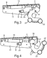
- a side view of the hinge 15 is shown.
- This comprises, as a hinge part, a hinge housing 17 and a further hinged part hingedly connected thereto in the form of a hinge hook 18.
- the hinge hook 18 is rotatably connected to the hinge housing 17, in which respect an axis of rotation A is formed, which runs perpendicular to the plane of the figure.
- a gas tension spring damping device 19 which is both rotatably mounted with the hinge housing 17 and rotatably mounted with the hinge hook 18 is connected.
- one end 19 a is mounted rotatably mounted about an axis B on the hinge housing 17.
- another end 19b of the damping device 19 is rotatably mounted about an axis C connected to the hinge hook 18.
- a rotatably mounted Auswerfelement 20 is arranged, which can be rotated about an axis D.
- the ejection element 20 is mechanically connected directly to the damping device 19.
- a locking and unlocking device 21 is also provided with which the closed state or the closed end position of the door 3 can be held or released.
- two relatively rotatably mounted rollers 22 and 23 are arranged on the hinge hook 18, which can also be referred to as a hinge sword.
- the closed end position of the door 3 performing component assembly in Fig. 2 In the embodiment, a button or a switch 24 on the housing 2 operated by a user, the locked state is released and the ejection element 20 according to the partial view in Fig. 2 pivoted upwards about the axis D. As a result, the damping device 19 is raised. Due to the coupling with the hinge hook 18, the hinge hook 18 is then pivoted about the axis A in accordance with the arrow there. The door 3 is moved by these movements of the closed end position in a door opening position.
- the ejection element 20 is positioned with its axis D so that it is positioned approximately centrally with respect to the position of the axes B and C with respect to the length of the distance of the axes B and C.
- Fig. 4 is a side view of the component assembly according to Fig. 2 and Fig. 3 shown, where the components are shown in an intermediate position between the closed and the open end position of the door 3.
- a locking pin 26 of the locking and unlocking unit 21 is engaged in a recess 27 of the hinge hook 18. The further movement of the door 3 is inhibited. In this specifically brought about position, the door can then be removed from the housing 2.
Landscapes
- Engineering & Computer Science (AREA)
- Chemical & Material Sciences (AREA)
- Combustion & Propulsion (AREA)
- Mechanical Engineering (AREA)
- General Engineering & Computer Science (AREA)
- Physics & Mathematics (AREA)
- Thermal Sciences (AREA)
- Electric Ovens (AREA)
- Closing And Opening Devices For Wings, And Checks For Wings (AREA)
Description
- Die Erfindung betrifft ein Haushaltsgerät mit einem Aufnahmeraum und einer Tür zum Verschließen des Aufnahmeraums, wobei die Tür im geöffneten Zustand in das Haushaltsgerät versenkbar ist.
- Es sind Backöfen bekannt, bei denen die frontseitige Tür zum Verschließen eines Garraums um eine feststehende Achse verschwenkbar ist. Die Tür ist somit sowohl im geschlossenen als auch im vollständig geöffneten Zustand stets außerhalb des Gehäuses des Haushaltsgeräts angeordnet.
- Darüber hinaus sind jedoch auch Backöfen bekannt, bei denen die Tür ausgehend von einer geschlossenen Stellung in eine offene Stellung verbracht werden kann, wobei dann in der vollständig geöffneten Endstellung die Tür nahezu vollständig in dem Gehäuse des Haushaltsgeräts versenkt bzw. eingeschoben ist. Die Tür ist darüber hinaus von einem Nutzer zu führen, sodass gegebenenfalls dann auch ein unerwünscht harter Anschlag in einer Endstellung erfolgt.
- Die
DE 1 274 306 B offenbart eine Back- und Bratröhre von Kochgeräten, insbesondere Herden, mit um die Unterkante schwenkbarer Back- und Bratofentür. - Die
WO 2007/082824 A2 offenbart eine Vorrichtung mit einer Tür. DieEP 0 442 565 A2 offenbart eine Beschickungstür für Haushaltsgeräte. Schließlich offenbart dieEP 2 189 725 A2 eine Hausgerätvorrichtung. - Es ist Aufgabe der vorliegenden Erfindung, ein Haushaltsgerät sowie ein Verfahren zum Betätigen einer Tür eines Haushaltsgeräts zu schaffen, mit welchem bzw. bei welchem eine in das Haushaltsgerät versenkbare Tür nutzerfreundlicher bewegbar ist.
- Diese Aufgabe wird durch eine Haushaltsgerät und ein Verfahren gemäß den unabhängigen Ansprüchen gelöst.
- Ein erfindungsgemäßes Haushaltsgerät umfasst einen Aufnahmeraum und eine Tür zum Verschließen des Aufnahmeraums. Die Tür ist im geöffneten Zustand in das Haushaltsgerät versenkbar bzw. versenkt angeordnet. Das Haushaltsgerät umfasst eine Dämpfungseinrichtung, mit welcher die Bewegung der Tür gedämpft ist. Durch eine derartige Ausgestaltung wird der Bewegungsweg der Tür zwischen den beiden Endstellungen gedämpft, sodass ein zu hartes Anschlagen in einer Endstellung vermieden ist. Darüber hinaus kann der gesamte Bewegungsablauf der Tür gleichmäßiger und ruckfreier erfolgen, sodass auch hier unerwünscht starke Krafteinwirkungen und daraus resultierender Verschleiß vermieden werden können.
- Durch die Dämpfungseinrichtung ist insbesondere der gesamte Bewegungsweg zwischen den beiden Endstellungen, der offenen und der geschlossenen Endstellung, der Tür gedämpft. Dies ist im Hinblick auf die oben genannten Aspekte besonders vorteilhaft. Darüber hinaus ermöglicht eine derartige Ausgestaltung auch eine besonders nutzerfreundliche Türbetätigung.
- Insbesondere ist es durch einen derartig permanent gedämpften Bewegungsablauf möglich, dass auch die Tür vollständig automatisch bewegt wird, sodass der Nutzer grundsätzlich gegebenenfalls nur noch die Initialisierung der Schließung oder Öffnung der Tür einleiten muss. Ein besonders nutzerfreundliches Bedienkonzept ist dadurch erreicht.
- Die Tür ist mit einem Türscharnier verbunden, mit dem die Dämpfungseinrichtung gekoppelt ist. Automatisch, wenn somit die Bewegung der Tür erfolgt, was zwangsweise auch die Bewegung des Türscharniers bedingt, wird somit durch die Kopplung auch automatisch die Dämpfungseinrichtung betätigt.
- Es ist vorgesehen, dass die Tür, insbesondere ein Türscharnier, ein Auswerfelement aufweist, mit welchem die Tür in einer geschlossenen Endstellung in eine Teilöffnungsposition bringbar ist. Dies ist eine besonders hervorzuhebende Ausführung, da zunächst durch einen spezifischen Initialisierungsvorgang, ein Betätigen des Auswerfelements, ein Zustand geschaffen werden kann, bei dem die Tür in eine spezifische Position verbringbar ist, von der aus die weitere vollständige automatische eigene Bewegung, die gedämpft ist, in die offene Endstellung erfolgen kann.
- Das Auswerfelement ist an einem als Scharniergehäuse ausgebildeten Scharnierteil angeordnet. Beispielsweise kann durch Betätigen eines Schalters oder Tasters des Haushaltsgeräts dieses Auswerfelement betätigt werden und die Tür wird dann bereits in diesem Szenario automatisch von der geschlossenen Endstellung in diese Teilöffnungsposition gebracht. Ist diese Teilöffnungsposition erreicht, so ist es nicht mehr erforderlich, dass der Nutzer weitere Hand an die Tür anlegt, sondern mit dem Erreichen der Teilöffnungsposition erfolgt dann die weitere Bewegung der Tür in die vollständig geschlossene Endstellung automatisch. Durch eine derartige Bewegungsstruktur kann somit erreicht werden, dass die Tür von der vollständig geschlossenen Endstellung in die vollständig offene Endstellung verbracht werden kann, ohne dass der Nutzer die Tür diesbezüglich betätigt. Lediglich das Drücken oder Kippen eines entsprechenden Schalters löst dann das Bewegungsszenario aus.
- Die Dämpfungseinrichtung und das zumindest eine Türscharnier sind so verbunden, dass mit dem Erreichen der Zwischenstellung der Dämpfungseinrichtung und der Türöffnungsposition der Tür im weiteren Bewegungsablauf ein automatisches gedämpftes Überführen der Tür in eine in das Haushaltsgerät versenkte offene Endstellung durchführbar ist. Die Vorteile dazu wurden bereits oben erwähnt.
- Es ist vorgesehen, dass das Auswerfelement in einer geschlossenen Endstellung der Tür mit der Dämpfungseinrichtung gekoppelt ist und mit einem Betätigen einer Verriegelungs- und Entriegelungseinheit des Türscharniers ist die Dämpfungseinrichtung durch das Auswerfelement in eine Zwischenstellung verschiebbar.
- Durch die Verriegelungs- und Entriegelungseinheit ist auch die Tür in der geschlossenen Endstellung haltbar.
- Vorzugsweise ist vorgesehen, dass das Türscharnier zwei relativ zueinander bewegbare und miteinander verbundene Scharnierteile aufweist, und die Dämpfungseinrichtung mit den beiden Scharnierteilen verbunden ist. Durch diese Kopplung werden ganz spezifisch Bewegungsabläufe im Hinblick auf die Bewegung der Tür und der damit verbundenen ausreichenden und somit einerseits nicht zu starken und auch nicht zu schwachen Dämpfung erzielt.
- Vorzugsweise ist vorgesehen, dass das Türscharnier als erstes Scharnierteil ein Gehäuse aufweist, und als zweites Scharnierteil einen Scharnierhaken umfasst, wobei an dem Scharnierhaken zumindest eine Rolle angeordnet ist, die relativ zum Scharnierhaken drehbar ist. Dies ist gerade bei den versenkbaren Türen von besonderer Vorteilhaftigkeit, da somit der Scharnierhaken mit der zumindest einen Rolle sehr leichtgängig geführt in das Gehäuse des Haushaltsgeräts beim Öffnen der Tür eingleiten kann, andererseits ausgehend von der versenkten und somit vollständig offenen Endstellung der Tür auch wieder besonders leichtgängig geführt in die geschlossene Stellung übergehen kann. Gerade gekoppelt mit der Relativbewegung des Scharnierhakens gegenüber dem Scharniergehäuse ist diese Rollenführung besonders hervorzuheben.
- Ein Scharniergehäuse ist üblicherweise ein längliches, relativ großes Bauteil, in dem auch weitere Komponenten des Scharniers angeordnet sind. Es benötigt deutlich mehr Bauraum als der Scharnierhaken, der auch als Scharnierschwert bezeichnet werden kann. Das Scharniergehäuse kann zur Aufnahme weiterer Funktionsteile der Tür oder des Scharniers vorgesehen sein.
- Vorzugsweise ist die Dämpfungseinrichtung relativ bewegbar an dem Türscharnier gelagert. Insbesondere ist die Dämpfungseinrichtung mit den jeweils gegenüberliegenden Seiten einerseits mit dem Scharniergehäuse und andererseits mit dem Scharnierhaken jeweils drehbar gelagert verbunden. Eine besonders vielfältige und dennoch gekoppelte Bewegungsstruktur der Bauteile zueinander ist dadurch gewährleistet, was einerseits im Hinblick auf den Bewegungsablauf der Tür, insbesondere im Hinblick auf das Einsenken in das Gehäuse des Haushaltsgeräts, und andererseits im Hinblick auf die gewünschte und gezielte Dämpfung dieser Bewegung aufeinander abgestimmt ist.
- Vorzugsweise ist vorgesehen, dass das Auswerfelement mittig zwischen einem Anbindungspunkt der Dämpfungseinrichtung an dem Scharniergehäuse und einem Anbindungspunkt eines als weiteres Scharnierteil ausgebildeten Scharnierhakens angeordnet ist. Im Hinblick auf die Bewegungsabläufe ist dies eine besonders hervorzuhebende Position, die vorteilhafte Hebelwirkungen generiert.
- Vorzugsweise ist das Auswerfelement an dem Scharniergehäuse oder dem Scharnierhaken angeordnet.
- Vorzugsweise ist vorgesehen, dass das Auswerfelement eine Feder ist.
- In vorteilhafter Ausführung ist vorgesehen, dass die Dämpfungseinrichtung eine Gaszugfeder ist.
- Die Gaszugfeder ist vorzugsweise drehbar an dem Scharnierhaken gelagert. Die Gaszugfeder kann durch unterschiedliche Befüllungsstärken individuell auf das Türgewicht bzw. auf die Anforderungen des Nutzers des Haushaltsgeräts an das Öffnungsverhalten der Tür abgestimmt werden.
- Optional zur Gaszugfeder kann die Dämpfungseinrichtung auch als Federstrebe oder als anderweitiger Federmechanismus ausgebildet sein.
- Es kann vorgesehen sein, dass die Dämpfungseinrichtung direkt mit dem Scharnierhaken verbunden ist. Ebenso kann jedoch auch vorgesehen sein, dass diese Dämpfungseinrichtung über ein weiteres Zusatzelement oder mehrere weitere Zusatzelemente mit dem Scharnierhaken gekoppelt ist. Es kann auch vorgesehen sein, dass die Dämpfungseinrichtung in dem Scharniergehäuse angeordnet ist oder jedoch auch außerhalb dazu angeordnet, jedoch mit dem Scharniergehäuse verbunden ist.
- Das Auswerfelement kann insbesondere als Schenkelfeder ausgebildet sein. Ebenso kann jedoch auch eine Druckfeder oder eine Zugfeder ausgebildet sein. Es kann vorgesehen sein, dass das Auswerfelement am Scharnierhaken oder radial am Befestigungsbolzen des Scharnierhakens angebracht ist.
- Vorzugsweise ist vorgesehen, dass in der geschlossenen Endstellung der Tür das Auswerfelement vorgespannt ist, um dann bei Betätigung eines entsprechenden Schalters oder Tasters die erforderliche Energie zum Auswerfen der Tür aufzubringen. Wird die Verriegelungs- und Entriegelungseinheit gelöst, so drückt das Auswerfelement die vorzugsweise als Gaszugfeder ausgebildete Dämpfungseinrichtung und dann auch den damit gekoppelten Scharnierhaken nach oben. Hierdurch wird die Tür so weit geöffnet und der Scharnierhaken so weit gedreht, bis sich die Türöffnungsstellung einstellt. Diese ist dann so definiert, dass die Tür durch ihre Schwerkraft von alleine dann den weiteren Bewegungsweg nach unten bis zur vollständig geöffneten Endstellung durchführt. Diese selbstständige weitere Öffnungsbewegung wird dann durch die Dämpfungseinrichtung gebremst.
- Der Scharnierhaken dreht sich vorzugsweise in einem Winkelintervall zwischen 50° und 130°, insbesondere zwischen 60° und 120°. Die Tür fährt durch ihre Restgeschwindigkeit vollständig in das Gehäuse des Haushaltsgeräts ein.
- Beim Schließen der Tür unterstützt die Dämpfungseinrichtung den Nutzer.
- Der Ausbau der Tür kann ebenfalls erfolgen. Hierzu kann vorgesehen sein, dass der Scharnierhaken oder ein mit dem Scharnierhaken verbundenes Teil durch einen Verriegelungsstift blockiert ist. Dies erfolgt in einer spezifischen Stellung, in der dann die Tür entnommen werden kann.
- Des Weiteren betrifft die Erfindung ein Verfahren zum Betätigen einer Tür eines Haushaltsgeräts, bei welchem die Tür zwischen einer geschlossenen und einer offenen Endstellung zum Verschließen oder Freigeben eines Aufnahmeraums des Haushaltsgeräts bewegt wird, und bei Überführen in die offene Endstellung in dem Haushaltsgerät versenkt wird. Die Bewegung der Tür zwischen den Endstellungen wird durch eine Dämpfungseinrichtung gedämpft. Insbesondere wird die gesamte Bewegung zwischen den Endstellungen gedämpft.
- Ausgehend von der geschlossenen Endstellung wird die Tür in eine Türöffnungsstellung gebracht, indem insbesondere zunächst eine Verriegelungs- und Entriegelungseinheit betätigt wird, durch welche dann ein Auswerfelement des Haushaltsgeräts aktiviert wird, sodass ausgehend von der geschlossenen Endstellung die Tür in eine Türöffnungsstellung gebracht wird. Von dieser bewegt sich dann die Tür automatisch in die vollständig offene Endstellung.
- Mit dem Betätigen eines Tasters oder Schalters wird die Verriegelungs- und Entriegelungseinheit betätigt und das Auswerfelement aktiviert, durch welches dann die Dämpfungseinrichtung verschoben wird. Indem die Dämpfungseinrichtung mit einem Türscharnier gekoppelt wird, wird auch dieses Türscharnier, insbesondere ein mit der Dämpfungseinrichtung gekoppelter Scharnierhaken, bewegt.
- Weitere Merkmale der Erfindung ergeben sich aus den Ansprüchen, den Figuren und der Figurenbeschreibung. Die vorstehend in der Beschreibung genannten Merkmale und Merkmalskombinationen als auch die in den Figuren alleine gezeigten Merkmale und Merkmalskombinationen und/oder in der Figurenbeschreibung alleine gezeigten Merkmale und Merkmalskombinationen sind nicht nur in der jeweils angegebenen Kombination, sondern auch in anderen Kombinationen oder in Alleinstellung verwendbar, ohne den Rahmen der Erfindung zu verlassen.
- Ein Ausführungsbeispiel der Erfindung wird nachfolgend anhand schematischer Zeichnungen näher erläutert. Es zeigen:
- Fig. 1
- eine perspektivische Darstellung eines Ausführungsbeispiels eines erfindungsgemäßen Haushaltsgeräts;
- Fig. 2
- eine Seitenansicht auf ein Ausführungsbeispiel von Stellungen von mechanischen Komponenten des Haushaltsgeräts im geschlossenen Zustand der Tür;
- Fig. 3
- eine Seitenansicht der Komponenten gemäß
Fig. 2 in der geöffneten Endstellung der Tür ; und - Fig. 4
- eine Seitenansicht der Komponenten gemäß
Fig. 2 undFig. 3 in einer Zwischenstellung zur Entnahme der Tür von einem Gehäuse des Haushaltsgeräts. - In den Figuren werden gleiche oder funktionsgleiche Elemente mit den gleichen Bezugszeichen versehen.
- In
Fig. 1 ist in einer schematischen perspektivischen Darstellung ein als Backofen 1 ausgebildetes Haushaltsgerät gezeigt. - Der Backofen 1 umfasst ein Gehäuse 2, in welchem ein durch eine nicht dargestellte Muffel begrenzter Garraum ausgebildet ist. Der Garraum ist frontseitig durch eine Tür 3 verschließbar, die in
Fig. 1 in der geschlossenen Endstellung gezeigt ist. An der Frontseite der Tür 3 ist ein Griff 4 ausgebildet. - Darüber hinaus umfasst der Backofen 1 eine Bedienvorrichtung 5, die in der Position und Anzahl lediglich beispielhaft eine Anzeigeeinheit 6 und Bedienelemente 7 und 8 aufweist.
- Darüber hinaus sind ebenfalls im Hinblick auf Position und Anzahl lediglich beispielhaft dargestellte Kochzonen 9, 10, 11 und 12 gezeigt.
- Die Tür 3 kann in ihrem unteren Bereich 13 in das Gehäuse 2 eingeschoben bzw. versenkt werden, was bei dem Überführen der Tür 3 von der in
Fig. 1 gezeigten geschlossenen Endstellung in die vollständig offene Endstellung der Fall ist. Die Tür 3 ist dann in einem Freiraum 14 des Gehäuses 2 versenkt eingeschoben angeordnet. - Die Tür 3 ist mit beispielhaft gezeigten und gekennzeichneten Türscharniere 15 und 16 verbunden.
- In
Fig. 2 ist eine Seitenansicht des Scharniers 15 gezeigt. Dieses umfasst als ein Scharnierteil ein Scharniergehäuse 17 und ein damit drehbar verbundenes weiteres Scharnierteil in Form eines Scharnierhakens 18. Der Scharnierhaken 18 ist mit dem Scharniergehäuse 17 drehbar verbunden, wobei diesbezüglich eine Drehachse A ausgebildet ist, welche senkrecht zur Figurenebene verläuft. - Darüber hinaus ist eine als Gaszugfeder ausgebildete Dämpfungseinrichtung 19 vorgesehen, die sowohl drehbar gelagert mit dem Scharniergehäuse 17 als auch drehbar gelagert mit dem Scharnierhaken 18 verbunden ist. Dazu ist ein Ende 19a um eine Achse B drehbar gelagert an dem Scharniergehäuse 17 befestigt. Darüber hinaus ist ein weiteres Ende 19b der Dämpfungseinrichtung 19 um eine Achse C drehbar gelagert mit dem Scharnierhaken 18 verbunden.
- Darüber hinaus ist vorgesehen, dass im Ausführungsbeispiel an dem Scharniergehäuse 17 ein drehbar gelagertes Auswerfelement 20 angeordnet ist, welches um eine Achse D gedreht werden kann. Das Auswerfelement 20 ist direkt mit der Dämpfungseinrichtung 19 mechanisch verbunden.
- Darüber hinaus ist auch noch eine Verriegelungs- und Entriegelungseinrichtung 21 vorgesehen, mit der der geschlossene Zustand bzw. die geschlossene Endstellung der Tür 3 gehalten oder freigegeben werden kann.
- Darüber hinaus sind an dem Scharnierhaken 18, welcher auch als Scharnierschwert bezeichnet werden kann, zwei relativ dazu drehbar gelagerte Rollen 22 und 23 angeordnet.
- Wird nun ausgehend von dieser die geschlossene Endstellung der Tür 3 darstellenden Komponentenanordnung in
Fig. 2 im Ausführungsbeispiel eine Taste oder ein Schalter 24 am Gehäuse 2 durch einen Nutzer betätigt, so wird der verriegelte Zustand gelöst und das Auswerfelement 20 gemäß der Teildarstellung inFig. 2 nach oben um die Achse D geschwenkt. Dadurch wird die Dämpfungseinrichtung 19 angehoben. Aufgrund der Kopplung mit dem Scharnierhaken 18 wird dann der Scharnierhaken 18 um die Achse A gemäß dem dortigen Pfeil verschwenkt. Die Tür 3 wird durch diese Bewegungsabläufe von der geschlossenen Endstellung in eine Türöffnungsstellung verbracht. - Ausgehend von dieser wird dann aufgrund der Schwerkraft der Tür 3 auch automatisch das weitere Bewegen der Tür 3 in die vollständig offene Endstellung durchgeführt. Dabei gleiten die Rollen 22 und 23 in Führungen in den Raum 14. Ist die Tür 3 dann in der vollständig offenen Endstellung durch die automatische Bewegungsführung angekommen, so haben die Komponenten gemäß der Darstellung in
Fig. 2 dann die inFig. 3 gezeigte relative Stellung zueinander eingenommen. - Durch die Dämpfungseinrichtung 19 ist der gesamte Bewegungsweg zwischen der geschlossenen Endstellung und der offenen Endstellung der Tür 3 spezifisch gedämpft.
- Wie aus der Darstellung in
Fig. 3 zu erkennen ist, ist in dieser offenen Endstellung der Scharnierhaken 18 an einem Anschlag 25 anliegend. Wie aus den Darstellungen inFig. 2 undFig. 3 zu erkennen ist, ist das Auswerfelement 20 mit seiner Achse D so positioniert, dass es im Hinblick auf die Lage der Achsen B und C im Hinblick auf die Länge des Abstands der Achsen B und C in etwa mittig positioniert ist. - In
Fig. 4 ist eine Seitenansicht der Komponentenanordnung gemäßFig. 2 undFig. 3 gezeigt, wobei dort die Komponenten in einer Zwischenstellung zwischen der geschlossenen und der offenen Endstellung der Tür 3 gezeigt sind. In dieser Zwischenstellung ist ein Verriegelungsstift 26 der Verriegelungs- und Entriegelungseinheit 21 in eine Aussparung 27 des Scharnierhakens 18 eingerastet. Die weitere Bewegung der Tür 3 ist dadurch gehemmt. In dieser spezifisch herbeigeführten Stellung kann die Tür dann von dem Gehäuse 2 abgenommen werden. - Im in
Fig. 2 gezeigten geschlossenen Zustand bzw. in der geschlossenen Endstellung der Tür 3 ist das Auswerfelement 20 vorgespannt angeordnet, sodass dann beim Überführen in die Türöffnungsstellung ausreichend Energie gegeben ist, um einerseits den Dämpfer bzw. die Dämpfungseinrichtung 19 nach oben zu drücken und damit auch die Bewegung des Scharnierhakens 18 automatisch zu generieren. -
- 1
- Backofen
- 2
- Gehäuse
- 3
- Tür
- 4
- Griff
- 5
- Bedienvorrichtung
- 6
- Anzeigeeinheit
- 7,8
- Bedienelemente
- 9, 10, 11, 12
- Kochzonen
- 13
- Bereich
- 14
- Freiraum
- 15, 16
- Türscharniere
- 17
- Scharniergehäuse
- 18
- Scharnierhaken
- 19
- Dämpfungseinrichtung
- 19a, 19b
- Enden
- 20
- Auswerfelement
- 21
- Verriegelungs- und Entriegelungseinrichtung
- 22, 23
- Rollen
- 24
- Taste/Schalter
- 25
- Anschlag
- 26
- Verriegelungsstift
- 27
- Aussparung
Claims (10)
- Haushaltsgerät (1) mit einem Aufnahmeraum und einer Tür (3) zum Verschließen des Aufnahmeraums, wobei die Tür (3) im geöffneten Zustand in das Haushaltsgerät (1) versenkt ist, wobei das Haushaltsgerät (1) eine Dämpfungseinrichtung (19) aufweist, mit welcher die gesamte Bewegung der Tür (3) zwischen einer offenen und einer geschlossenen Endstellung gedämpft ist, dadurch gekennzeichnet, dass die Tür (3), insbesondere ein Türscharnier (15, 16), ein Auswerfelement (20) aufweist, mit welchem die Tür (3) in einer geschlossenen Endstellung in eine von der offenen Endstellung unterschiedliche Teilöffnungsposition bringbar ist, wobei das Auswerfelement (20) an einem als Scharniergehäuse (17) ausgebildeten Scharnierteil angeordnet ist, wobei das Auswerfelement (20) in einer geschlossenen Endstellung der Tür (3) mit der Dämpfungseinrichtung (19) gekoppelt ist und mit einem Betätigen einer Verriegelungs- und Entriegelungseinheit (21) des Türscharniers (15, 16) die Dämpfungseinrichtung (19) durch das Auswerfelement (20) in eine Zwischenstellung verschiebbar ist, und wobei die Dämpfungseinrichtung (19) und das Türscharnier (15, 16) so verbunden sind, dass mit dem Erreichen der Zwischenstellung der Dämpfungseinrichtung (19) und der Türöffnungsposition im weiteren Bewegungsablauf ein aufgrund der Schwerkraft der Tür (3) automatisches gedämpftes Überführen der Tür (3) in eine in das Haushaltsgerät (1) versenkte offene Endstellung durchführbar ist.
- Haushaltsgerät (1) nach Anspruch 1, dadurch gekennzeichnet, dass die Tür (3) mit einem Türscharnier (15, 16) verbunden ist, mit dem die Dämpfungseinrichtung (19) gekoppelt ist.
- Haushaltsgerät (1) nach Anspruch 2, dadurch gekennzeichnet, dass das Türscharnier (15, 16) zwei relativ zueinander bewegbare und miteinander verbundene Scharnierteile (17, 18) aufweist, und die Dämpfungseinrichtung (19) mit beiden Scharnierteilen (17, 18) verbunden ist.
- Haushaltsgerät (1) nach Anspruch 2 oder 3, dadurch gekennzeichnet, dass das Türscharnier (15, 16) als erstes Scharnierteil ein Scharniergehäuse (17) aufweist und als zweites Scharnierteil einen Scharnierhaken (18) umfasst, wobei an dem Scharnierhaken (18) zumindest eine Rolle (22, 23) angeordnet ist, die relativ zum Scharnierhaken (18) drehbar ist.
- Haushaltgerät (1) nach einem der Ansprüche 2 bis 4, dadurch gekennzeichnet, dass die Dämpfungseinrichtung (19) relativ bewegbar an dem Türscharnier (15, 16) gelagert ist.
- Haushaltsgerät (1) nach einem der vorhergehenden Ansprüche, dadurch gekennzeichnet, dass das Auswerfelement (20) im Hinblick auf die Länge eines Abstands zwischen einem Anbindungspunkt (B) der Dämpfungseinrichtung (19) an dem Scharniergehäuse (17) und einem Anbindungspunkt (C) eines als weiteres Scharnierteil ausgebildeten Scharnierhakens (18) mittig angeordnet ist.
- Haushaltsgerät (1) nach Anspruch 6, dadurch gekennzeichnet, dass das Auswerfelement (20) an dem Scharniergehäuse (17) oder dem Scharnierhaken (18) angeordnet ist.
- Haushaltsgerät (1) nach einem der vorhergehenden Ansprüche, dadurch gekennzeichnet, dass das Auswerfelement (20) eine Feder ist.
- Haushaltsgerät (1) nach einem der vorhergehenden Ansprüche, dadurch gekennzeichnet, dass die Dämpfungseinrichtung (20) eine Gaszugfeder ist.
- Verfahren zum Betätigen einer Tür (3) eines Haushaltsgeräts (1), bei welchem die Tür (3) zwischen einer geschlossenen und einer offenen Endstellung zum Verschließen oder Freigeben eines Aufnahmeraums des Haushaltsgeräts (1) bewegt wird, und bei Überführen in die offene Endstellung in dem Haushaltsgerät (1) versenkt wird, wobei die Bewegung der Tür (3), insbesondere die gesamte Bewegung der Tür (3) zwischen einer offenen und einer geschlossenen Endstellung, durch eine Dämpfungseinrichtung (19) gedämpft wird, dadurch gekennzeichnet, dass ausgehend von der geschlossenen Endstellung die Tür (3) in eine Türöffnungsstellung gebracht wird, in dem die Dämpfungseinrichtung (19) durch ein Auswerfelement (20) verschoben wird und in dieser Türöffnungsstellung die miteinander drehbar verbundenen Scharnierteile (17, 18) eines Türscharniers (15, 16), an denen die Dämpfungseinrichtung (19) drehbar gelagert wird, so zueinander positioniert werden, dass das Überführen der Tür (3) von der Türöffnungsstellung in die offene versenkte Endstellung automatisch durchgeführt wird, wobei das Auswerfelement (20) in einer geschlossenen Endstellung der Tür (3) mit der Dämpfungseinrichtung (19) gekoppelt ist und mit einem Betätigen einer Verriegelungs- und Entriegelungseinheit (21) des Türscharniers (15, 16) die Dämpfungseinrichtung (19) durch das Auswerfelement (20) in eine Zwischenstellung verschoben wird, und wobei die Dämpfungseinrichtung (19) und das Türscharnier (15, 16) so verbunden sind, dass mit dem Erreichen der Zwischenstellung der Dämpfungseinrichtung (19) und der Türöffnungsposition im weiteren Bewegungsablauf ein aufgrund der Schwerkraft der Tür (3) automatisches gedämpftes Überführen der Tür (3) in eine in das Haushaltsgerät (1) versenkte offene Endstellung durchgeführt wird.
Applications Claiming Priority (1)
| Application Number | Priority Date | Filing Date | Title |
|---|---|---|---|
| DE102011083512A DE102011083512A1 (de) | 2011-09-27 | 2011-09-27 | Haushaltsgerät mit einem Aufnahmeraum und einer Tür zum Verschließen des Aufnahmeraums, sowie Verfahren zum Betätigen einer Tür eines Haushaltsgeräts |
Publications (2)
| Publication Number | Publication Date |
|---|---|
| EP2574712A1 EP2574712A1 (de) | 2013-04-03 |
| EP2574712B1 true EP2574712B1 (de) | 2017-03-01 |
Family
ID=46888946
Family Applications (1)
| Application Number | Title | Priority Date | Filing Date |
|---|---|---|---|
| EP12185061.4A Active EP2574712B1 (de) | 2011-09-27 | 2012-09-19 | Haushaltsgerät mit einem Aufnahmeraum und einer Tür zum Verschließen des Aufnahmeraums, sowie Verfahren zum Betätigen einer Tür eines Haushaltsgeräts |
Country Status (3)
| Country | Link |
|---|---|
| EP (1) | EP2574712B1 (de) |
| DE (1) | DE102011083512A1 (de) |
| ES (1) | ES2621274T3 (de) |
Families Citing this family (18)
| Publication number | Priority date | Publication date | Assignee | Title |
|---|---|---|---|---|
| DE102012222161A1 (de) * | 2012-12-04 | 2014-06-05 | BSH Bosch und Siemens Hausgeräte GmbH | Gargerät mit versenkbarer Tür und höhenverstellbarer Führungskulisse |
| EP2801762B1 (de) * | 2013-05-08 | 2018-01-17 | Electrolux Appliances Aktiebolag | Ofen umfassend eine Tür die zur Seite öffnet und einen Dämpfer der Türbewegung |
| DE102013225401A1 (de) | 2013-12-10 | 2015-06-11 | BSH Hausgeräte GmbH | Haushaltsgerät mit einer in einen Verstauraum einfahrbaren Tür und Verfahren zum öffnen und Schließen einer Tür eines Haushaltsgeräts |
| DE102013225402A1 (de) | 2013-12-10 | 2015-06-11 | BSH Hausgeräte GmbH | Haushaltsgerät mit einer in einem Stauraum versenkbaren Tür und verschiebbarer Drehachse einer Lagereinheit sowie Verfahren zum öffnen und Schließen einer derartigen Tür |
| DE102013225403A1 (de) * | 2013-12-10 | 2015-06-11 | BSH Hausgeräte GmbH | Haushaltsgerät mit einer in einem Verstauraum versenkbaren Tür mit vertikaler Lageveränderungsmöglichkeit einer Drehachse einer Lagereinheit sowie Verfahren zum öffnen und Schließen einer Tür |
| DE102015206577A1 (de) | 2015-04-13 | 2016-10-13 | BSH Hausgeräte GmbH | Haushaltsgerät mit einer in einem Verstauraum versenkbaren Tür mit elliptischer Kulisse zur Bewegung eines Lagerbügels einer Tür-Lagereinheit |
| DE102015206576A1 (de) | 2015-04-13 | 2016-10-13 | BSH Hausgeräte GmbH | Haushaltsgerät mit einer in einem Verstauraum versenkbaren Tür mit spezifischer Lagereinheit |
| ITUB20154268A1 (it) * | 2015-10-09 | 2017-04-09 | Giulio Manzoni | Cinematismo per ruotare verso il basso in modo controllato una qualsivoglia struttura tramite due molle a gas appaiate ed asincrone per ogni lato. |
| DE102015226009A1 (de) | 2015-12-18 | 2017-06-22 | BSH Hausgeräte GmbH | Gargerät mit einer Türöffnungsvorrichtung zum automatischen Verbringen einer Tür in eine Zwischenstellung sowie Verfahren zum Öffnen einer Tür eines Gargeräts |
| DE102017207980A1 (de) | 2017-05-11 | 2018-11-15 | BSH Hausgeräte GmbH | Gargerät mit einer Seilzugvorrichtung zum automatischen Schwenken einer Tür |
| EP3444531A1 (de) * | 2017-08-14 | 2019-02-20 | Electrolux Appliances Aktiebolag | Türöffnungssystem für ein küchengerät |
| DE102018201949A1 (de) | 2018-02-08 | 2019-08-08 | BSH Hausgeräte GmbH | Gargerät mit einer in einen Verstauraum versenkbaren Tür mit einem spezifischen Koppelmodul, sowie Verfahren zum Bewegen einer Tür |
| DE102018201950A1 (de) | 2018-02-08 | 2019-08-08 | BSH Hausgeräte GmbH | Gargerät mit einem Technikteil für eine versenkbare Tür, welches eine Führungsbahn in einer oberen Höhenhälfte des Technikteils aufweist |
| DE102019202418A1 (de) * | 2019-02-22 | 2020-08-27 | BSH Hausgeräte GmbH | Gargerät mit einer spezifischen Dämpfungseinheit zwischen Führungsbahnen einer Führungsvorrichtung für eine versenkbare Tür |
| EP3722546A1 (de) * | 2019-04-09 | 2020-10-14 | Apparatebau Gronbach S.R.L. | Scharnier für ein gerät, insbesondere für ein küchen- und/oder haushaltsgerät, sowie gerät, insbesondere küchen- und/oder haushaltsgerät |
| IT201900005596A1 (it) * | 2019-04-11 | 2020-10-11 | Brera Cerniere Srl | Elettrodomestico |
| CN113216776B (zh) * | 2021-04-30 | 2022-12-09 | 广东美的厨房电器制造有限公司 | 门锁装置及烹饪器具 |
| CN113397403B (zh) * | 2021-07-29 | 2022-12-27 | 广东美的厨房电器制造有限公司 | 门锁装置及烹饪器具 |
Family Cites Families (7)
| Publication number | Priority date | Publication date | Assignee | Title |
|---|---|---|---|---|
| US2925081A (en) * | 1957-03-06 | 1960-02-16 | Borg Warner | Slide-away door structure |
| DE1274306B (de) * | 1960-09-23 | 1968-08-01 | Mills Prod Inc | Back- und Bratroehre von Kochgeraeten, insbesondere Herden, mit um die Unterkante schwenkbarer Back- und Bratroehrentuer |
| DE3933719C2 (de) * | 1989-10-09 | 1994-02-03 | Bosch Siemens Hausgeraete | Beschickungstür für Haushaltsgeräte |
| DE102005044343A1 (de) * | 2005-09-16 | 2007-03-22 | BSH Bosch und Siemens Hausgeräte GmbH | Schließvorrichtung für eine Tür eines Haushaltsgeräts |
| DE102006002409A1 (de) * | 2006-01-18 | 2007-07-19 | BSH Bosch und Siemens Hausgeräte GmbH | Vorrichtung mit einer Tür |
| DE102008010497A1 (de) * | 2008-02-22 | 2009-08-27 | BSH Bosch und Siemens Hausgeräte GmbH | Hausgerätvorrichtung |
| DE102008010526A1 (de) * | 2008-02-22 | 2009-08-27 | BSH Bosch und Siemens Hausgeräte GmbH | Hausgerätvorrichtung |
-
2011
- 2011-09-27 DE DE102011083512A patent/DE102011083512A1/de not_active Withdrawn
-
2012
- 2012-09-19 EP EP12185061.4A patent/EP2574712B1/de active Active
- 2012-09-19 ES ES12185061.4T patent/ES2621274T3/es active Active
Non-Patent Citations (1)
| Title |
|---|
| None * |
Also Published As
| Publication number | Publication date |
|---|---|
| ES2621274T3 (es) | 2017-07-03 |
| EP2574712A1 (de) | 2013-04-03 |
| DE102011083512A1 (de) | 2013-03-28 |
Similar Documents
| Publication | Publication Date | Title |
|---|---|---|
| EP2574712B1 (de) | Haushaltsgerät mit einem Aufnahmeraum und einer Tür zum Verschließen des Aufnahmeraums, sowie Verfahren zum Betätigen einer Tür eines Haushaltsgeräts | |
| EP2174572B1 (de) | Öffnungs- und Schließvorrichtung für ein Schubelement | |
| DE102015226009A1 (de) | Gargerät mit einer Türöffnungsvorrichtung zum automatischen Verbringen einer Tür in eine Zwischenstellung sowie Verfahren zum Öffnen einer Tür eines Gargeräts | |
| EP2845532B1 (de) | Haushaltgerät mit automatischem Türöffnungsmechanismus | |
| EP3622223B1 (de) | Gargerät mit einer seilzugvorrichtung zum automatischen schwenken einer tür | |
| EP3105396B1 (de) | Lageranordnung für eine tür | |
| EP3783266B1 (de) | Gargerät mit einem mittels einer tür verschliessbaren garraum | |
| DE102008011650A1 (de) | Haushaltsgerätetür und Verfahren zum Bedienen der Haushaltsgerätetür | |
| EP2540940B1 (de) | Scharnier für eine tür eines hausgeräts, tür mit einem derartigen scharnier sowie hausgerät mit einem entsprechenden scharnier als auch verfahren zum betätigen eines türgriffs einer tür | |
| DE102011003818A1 (de) | Geschirrspülmaschine, insbesondere Haushalts-Geschirrspülmaschine | |
| EP2759669B1 (de) | Scharnier für einen herd | |
| EP3658824B1 (de) | Gargerät mit versenkbarer tür, die eine spezifische haltefeder für eine lagerbuchse aufweist | |
| DE10230708A1 (de) | Verriegelungsvorrichtung für Haushaltgeräte | |
| EP2581666B1 (de) | Tür für ein Haushaltsgerät, Haushaltsgerät mit einer Tür und Verfahren zum Bewegen eines Griffs einer Tür eines Haushaltsgeräts | |
| DE102012012165A1 (de) | Kühl- und/oder Gefriergerät | |
| EP2189726A2 (de) | Versenkbare Griffvorrichtung für eine Tür eines Hausgeräts und Tür für ein Hausgerät mit einer derartigen Griffvorrichtung | |
| EP3021047B1 (de) | Tür für ein haushaltsgerät und haushaltsgerät | |
| DE102011084571A1 (de) | Vorrichtung zur Behandlung von Lebensmitteln mit verbesserter Tür-Anbindung | |
| EP3199735B1 (de) | Scharnier, insbesondere für ein haushaltsgerät | |
| EP2884188B1 (de) | Haushaltsgerät mit einer in einem Stauraum versenkbaren Tür und verschiebbarer Drehachse einer Lagereinheit sowie Verfahren zum Öffnen und Schließen einer derartigen Tür | |
| EP2741015B1 (de) | Tür für ein Haushaltsgerät mit einem plattenartigen Greifteil und einem Greifteilöffner, Haushaltsgerät mit einer derartigen Tür sowie Verfahren zum Öffnen einer Tür eines Haushaltsgeräts | |
| EP4086418A1 (de) | System, umfassend ein möbel mit einer einbaunische und ein einbaugerät, und verfahren zum betrieb des systems | |
| EP3534752A2 (de) | Möbel mit einem motorischen antrieb für ein möbelteil sowie motorischer antrieb für ein möbel | |
| EP3324124B1 (de) | Gargerät mit türschloss | |
| EP2930436B1 (de) | Haushaltsgerät mit einer in einem Verstauraum versenkbaren Tür sowie Verfahren zum Öffnen und Schließen einer Tür eines Haushaltsgeräts |
Legal Events
| Date | Code | Title | Description |
|---|---|---|---|
| PUAI | Public reference made under article 153(3) epc to a published international application that has entered the european phase |
Free format text: ORIGINAL CODE: 0009012 |
|
| AK | Designated contracting states |
Kind code of ref document: A1 Designated state(s): AL AT BE BG CH CY CZ DE DK EE ES FI FR GB GR HR HU IE IS IT LI LT LU LV MC MK MT NL NO PL PT RO RS SE SI SK SM TR |
|
| AX | Request for extension of the european patent |
Extension state: BA ME |
|
| 17P | Request for examination filed |
Effective date: 20131004 |
|
| RBV | Designated contracting states (corrected) |
Designated state(s): AL AT BE BG CH CY CZ DE DK EE ES FI FR GB GR HR HU IE IS IT LI LT LU LV MC MK MT NL NO PL PT RO RS SE SI SK SM TR |
|
| 17Q | First examination report despatched |
Effective date: 20140613 |
|
| RAP1 | Party data changed (applicant data changed or rights of an application transferred) |
Owner name: BSH HAUSGERAETE GMBH |
|
| GRAP | Despatch of communication of intention to grant a patent |
Free format text: ORIGINAL CODE: EPIDOSNIGR1 |
|
| INTG | Intention to grant announced |
Effective date: 20161012 |
|
| GRAS | Grant fee paid |
Free format text: ORIGINAL CODE: EPIDOSNIGR3 |
|
| GRAA | (expected) grant |
Free format text: ORIGINAL CODE: 0009210 |
|
| AK | Designated contracting states |
Kind code of ref document: B1 Designated state(s): AL AT BE BG CH CY CZ DE DK EE ES FI FR GB GR HR HU IE IS IT LI LT LU LV MC MK MT NL NO PL PT RO RS SE SI SK SM TR |
|
| REG | Reference to a national code |
Ref country code: GB Ref legal event code: FG4D Free format text: NOT ENGLISH |
|
| REG | Reference to a national code |
Ref country code: CH Ref legal event code: EP Ref country code: AT Ref legal event code: REF Ref document number: 871563 Country of ref document: AT Kind code of ref document: T Effective date: 20170315 |
|
| REG | Reference to a national code |
Ref country code: IE Ref legal event code: FG4D Free format text: LANGUAGE OF EP DOCUMENT: GERMAN |
|
| REG | Reference to a national code |
Ref country code: DE Ref legal event code: R096 Ref document number: 502012009625 Country of ref document: DE |
|
| REG | Reference to a national code |
Ref country code: ES Ref legal event code: FG2A Ref document number: 2621274 Country of ref document: ES Kind code of ref document: T3 Effective date: 20170703 |
|
| REG | Reference to a national code |
Ref country code: NL Ref legal event code: MP Effective date: 20170301 |
|
| REG | Reference to a national code |
Ref country code: LT Ref legal event code: MG4D |
|
| PG25 | Lapsed in a contracting state [announced via postgrant information from national office to epo] |
Ref country code: FI Free format text: LAPSE BECAUSE OF FAILURE TO SUBMIT A TRANSLATION OF THE DESCRIPTION OR TO PAY THE FEE WITHIN THE PRESCRIBED TIME-LIMIT Effective date: 20170301 Ref country code: HR Free format text: LAPSE BECAUSE OF FAILURE TO SUBMIT A TRANSLATION OF THE DESCRIPTION OR TO PAY THE FEE WITHIN THE PRESCRIBED TIME-LIMIT Effective date: 20170301 Ref country code: LT Free format text: LAPSE BECAUSE OF FAILURE TO SUBMIT A TRANSLATION OF THE DESCRIPTION OR TO PAY THE FEE WITHIN THE PRESCRIBED TIME-LIMIT Effective date: 20170301 Ref country code: GR Free format text: LAPSE BECAUSE OF FAILURE TO SUBMIT A TRANSLATION OF THE DESCRIPTION OR TO PAY THE FEE WITHIN THE PRESCRIBED TIME-LIMIT Effective date: 20170602 Ref country code: NO Free format text: LAPSE BECAUSE OF FAILURE TO SUBMIT A TRANSLATION OF THE DESCRIPTION OR TO PAY THE FEE WITHIN THE PRESCRIBED TIME-LIMIT Effective date: 20170601 |
|
| PG25 | Lapsed in a contracting state [announced via postgrant information from national office to epo] |
Ref country code: BG Free format text: LAPSE BECAUSE OF FAILURE TO SUBMIT A TRANSLATION OF THE DESCRIPTION OR TO PAY THE FEE WITHIN THE PRESCRIBED TIME-LIMIT Effective date: 20170601 Ref country code: RS Free format text: LAPSE BECAUSE OF FAILURE TO SUBMIT A TRANSLATION OF THE DESCRIPTION OR TO PAY THE FEE WITHIN THE PRESCRIBED TIME-LIMIT Effective date: 20170301 Ref country code: LV Free format text: LAPSE BECAUSE OF FAILURE TO SUBMIT A TRANSLATION OF THE DESCRIPTION OR TO PAY THE FEE WITHIN THE PRESCRIBED TIME-LIMIT Effective date: 20170301 Ref country code: SE Free format text: LAPSE BECAUSE OF FAILURE TO SUBMIT A TRANSLATION OF THE DESCRIPTION OR TO PAY THE FEE WITHIN THE PRESCRIBED TIME-LIMIT Effective date: 20170301 |
|
| PG25 | Lapsed in a contracting state [announced via postgrant information from national office to epo] |
Ref country code: NL Free format text: LAPSE BECAUSE OF FAILURE TO SUBMIT A TRANSLATION OF THE DESCRIPTION OR TO PAY THE FEE WITHIN THE PRESCRIBED TIME-LIMIT Effective date: 20170301 |
|
| PG25 | Lapsed in a contracting state [announced via postgrant information from national office to epo] |
Ref country code: EE Free format text: LAPSE BECAUSE OF FAILURE TO SUBMIT A TRANSLATION OF THE DESCRIPTION OR TO PAY THE FEE WITHIN THE PRESCRIBED TIME-LIMIT Effective date: 20170301 Ref country code: IT Free format text: LAPSE BECAUSE OF FAILURE TO SUBMIT A TRANSLATION OF THE DESCRIPTION OR TO PAY THE FEE WITHIN THE PRESCRIBED TIME-LIMIT Effective date: 20170301 Ref country code: RO Free format text: LAPSE BECAUSE OF FAILURE TO SUBMIT A TRANSLATION OF THE DESCRIPTION OR TO PAY THE FEE WITHIN THE PRESCRIBED TIME-LIMIT Effective date: 20170301 Ref country code: CZ Free format text: LAPSE BECAUSE OF FAILURE TO SUBMIT A TRANSLATION OF THE DESCRIPTION OR TO PAY THE FEE WITHIN THE PRESCRIBED TIME-LIMIT Effective date: 20170301 Ref country code: SK Free format text: LAPSE BECAUSE OF FAILURE TO SUBMIT A TRANSLATION OF THE DESCRIPTION OR TO PAY THE FEE WITHIN THE PRESCRIBED TIME-LIMIT Effective date: 20170301 |
|
| PG25 | Lapsed in a contracting state [announced via postgrant information from national office to epo] |
Ref country code: SM Free format text: LAPSE BECAUSE OF FAILURE TO SUBMIT A TRANSLATION OF THE DESCRIPTION OR TO PAY THE FEE WITHIN THE PRESCRIBED TIME-LIMIT Effective date: 20170301 Ref country code: IS Free format text: LAPSE BECAUSE OF FAILURE TO SUBMIT A TRANSLATION OF THE DESCRIPTION OR TO PAY THE FEE WITHIN THE PRESCRIBED TIME-LIMIT Effective date: 20170701 Ref country code: PL Free format text: LAPSE BECAUSE OF FAILURE TO SUBMIT A TRANSLATION OF THE DESCRIPTION OR TO PAY THE FEE WITHIN THE PRESCRIBED TIME-LIMIT Effective date: 20170301 Ref country code: PT Free format text: LAPSE BECAUSE OF FAILURE TO SUBMIT A TRANSLATION OF THE DESCRIPTION OR TO PAY THE FEE WITHIN THE PRESCRIBED TIME-LIMIT Effective date: 20170703 |
|
| REG | Reference to a national code |
Ref country code: DE Ref legal event code: R097 Ref document number: 502012009625 Country of ref document: DE |
|
| PLBE | No opposition filed within time limit |
Free format text: ORIGINAL CODE: 0009261 |
|
| STAA | Information on the status of an ep patent application or granted ep patent |
Free format text: STATUS: NO OPPOSITION FILED WITHIN TIME LIMIT |
|
| PG25 | Lapsed in a contracting state [announced via postgrant information from national office to epo] |
Ref country code: DK Free format text: LAPSE BECAUSE OF FAILURE TO SUBMIT A TRANSLATION OF THE DESCRIPTION OR TO PAY THE FEE WITHIN THE PRESCRIBED TIME-LIMIT Effective date: 20170301 |
|
| 26N | No opposition filed |
Effective date: 20171204 |
|
| PG25 | Lapsed in a contracting state [announced via postgrant information from national office to epo] |
Ref country code: SI Free format text: LAPSE BECAUSE OF FAILURE TO SUBMIT A TRANSLATION OF THE DESCRIPTION OR TO PAY THE FEE WITHIN THE PRESCRIBED TIME-LIMIT Effective date: 20170301 |
|
| REG | Reference to a national code |
Ref country code: CH Ref legal event code: PL |
|
| PG25 | Lapsed in a contracting state [announced via postgrant information from national office to epo] |
Ref country code: MC Free format text: LAPSE BECAUSE OF FAILURE TO SUBMIT A TRANSLATION OF THE DESCRIPTION OR TO PAY THE FEE WITHIN THE PRESCRIBED TIME-LIMIT Effective date: 20170301 |
|
| REG | Reference to a national code |
Ref country code: IE Ref legal event code: MM4A |
|
| REG | Reference to a national code |
Ref country code: BE Ref legal event code: MM Effective date: 20170930 |
|
| PG25 | Lapsed in a contracting state [announced via postgrant information from national office to epo] |
Ref country code: LU Free format text: LAPSE BECAUSE OF NON-PAYMENT OF DUE FEES Effective date: 20170919 |
|
| REG | Reference to a national code |
Ref country code: FR Ref legal event code: ST Effective date: 20180531 |
|
| PG25 | Lapsed in a contracting state [announced via postgrant information from national office to epo] |
Ref country code: LI Free format text: LAPSE BECAUSE OF NON-PAYMENT OF DUE FEES Effective date: 20170930 Ref country code: IE Free format text: LAPSE BECAUSE OF NON-PAYMENT OF DUE FEES Effective date: 20170919 Ref country code: CH Free format text: LAPSE BECAUSE OF NON-PAYMENT OF DUE FEES Effective date: 20170930 |
|
| PG25 | Lapsed in a contracting state [announced via postgrant information from national office to epo] |
Ref country code: BE Free format text: LAPSE BECAUSE OF NON-PAYMENT OF DUE FEES Effective date: 20170930 Ref country code: FR Free format text: LAPSE BECAUSE OF NON-PAYMENT OF DUE FEES Effective date: 20171002 |
|
| PG25 | Lapsed in a contracting state [announced via postgrant information from national office to epo] |
Ref country code: MT Free format text: LAPSE BECAUSE OF FAILURE TO SUBMIT A TRANSLATION OF THE DESCRIPTION OR TO PAY THE FEE WITHIN THE PRESCRIBED TIME-LIMIT Effective date: 20170301 |
|
| REG | Reference to a national code |
Ref country code: AT Ref legal event code: MM01 Ref document number: 871563 Country of ref document: AT Kind code of ref document: T Effective date: 20170919 |
|
| PG25 | Lapsed in a contracting state [announced via postgrant information from national office to epo] |
Ref country code: AT Free format text: LAPSE BECAUSE OF NON-PAYMENT OF DUE FEES Effective date: 20170919 |
|
| PG25 | Lapsed in a contracting state [announced via postgrant information from national office to epo] |
Ref country code: HU Free format text: LAPSE BECAUSE OF FAILURE TO SUBMIT A TRANSLATION OF THE DESCRIPTION OR TO PAY THE FEE WITHIN THE PRESCRIBED TIME-LIMIT; INVALID AB INITIO Effective date: 20120919 |
|
| PG25 | Lapsed in a contracting state [announced via postgrant information from national office to epo] |
Ref country code: CY Free format text: LAPSE BECAUSE OF NON-PAYMENT OF DUE FEES Effective date: 20170301 |
|
| PG25 | Lapsed in a contracting state [announced via postgrant information from national office to epo] |
Ref country code: MK Free format text: LAPSE BECAUSE OF FAILURE TO SUBMIT A TRANSLATION OF THE DESCRIPTION OR TO PAY THE FEE WITHIN THE PRESCRIBED TIME-LIMIT Effective date: 20170301 |
|
| PGFP | Annual fee paid to national office [announced via postgrant information from national office to epo] |
Ref country code: ES Payment date: 20191023 Year of fee payment: 8 |
|
| PG25 | Lapsed in a contracting state [announced via postgrant information from national office to epo] |
Ref country code: TR Free format text: LAPSE BECAUSE OF FAILURE TO SUBMIT A TRANSLATION OF THE DESCRIPTION OR TO PAY THE FEE WITHIN THE PRESCRIBED TIME-LIMIT Effective date: 20170301 |
|
| PG25 | Lapsed in a contracting state [announced via postgrant information from national office to epo] |
Ref country code: AL Free format text: LAPSE BECAUSE OF FAILURE TO SUBMIT A TRANSLATION OF THE DESCRIPTION OR TO PAY THE FEE WITHIN THE PRESCRIBED TIME-LIMIT Effective date: 20170301 |
|
| REG | Reference to a national code |
Ref country code: ES Ref legal event code: FD2A Effective date: 20220118 |
|
| PG25 | Lapsed in a contracting state [announced via postgrant information from national office to epo] |
Ref country code: ES Free format text: LAPSE BECAUSE OF NON-PAYMENT OF DUE FEES Effective date: 20200920 |
|
| PGFP | Annual fee paid to national office [announced via postgrant information from national office to epo] |
Ref country code: GB Payment date: 20230921 Year of fee payment: 12 |
|
| PGFP | Annual fee paid to national office [announced via postgrant information from national office to epo] |
Ref country code: DE Payment date: 20230930 Year of fee payment: 12 |