EP2573643B1 - Computersystem und uhrenkonfigurationsverfahren dafür - Google Patents
Computersystem und uhrenkonfigurationsverfahren dafür Download PDFInfo
- Publication number
- EP2573643B1 EP2573643B1 EP11858207.1A EP11858207A EP2573643B1 EP 2573643 B1 EP2573643 B1 EP 2573643B1 EP 11858207 A EP11858207 A EP 11858207A EP 2573643 B1 EP2573643 B1 EP 2573643B1
- Authority
- EP
- European Patent Office
- Prior art keywords
- nodes
- node
- clock
- selecting
- computer system
- Prior art date
- Legal status (The legal status is an assumption and is not a legal conclusion. Google has not performed a legal analysis and makes no representation as to the accuracy of the status listed.)
- Active
Links
Images


Classifications
-
- G—PHYSICS
- G06—COMPUTING OR CALCULATING; COUNTING
- G06F—ELECTRIC DIGITAL DATA PROCESSING
- G06F1/00—Details not covered by groups G06F3/00 - G06F13/00 and G06F21/00
- G06F1/04—Generating or distributing clock signals or signals derived directly therefrom
-
- G—PHYSICS
- G06—COMPUTING OR CALCULATING; COUNTING
- G06F—ELECTRIC DIGITAL DATA PROCESSING
- G06F1/00—Details not covered by groups G06F3/00 - G06F13/00 and G06F21/00
- G06F1/04—Generating or distributing clock signals or signals derived directly therefrom
- G06F1/12—Synchronisation of different clock signals provided by a plurality of clock generators
-
- G—PHYSICS
- G06—COMPUTING OR CALCULATING; COUNTING
- G06F—ELECTRIC DIGITAL DATA PROCESSING
- G06F11/00—Error detection; Error correction; Monitoring
- G06F11/07—Responding to the occurrence of a fault, e.g. fault tolerance
- G06F11/16—Error detection or correction of the data by redundancy in hardware
- G06F11/1604—Error detection or correction of the data by redundancy in hardware where the fault affects the clock signals of a processing unit and the redundancy is at or within the level of clock signal generation hardware
-
- G—PHYSICS
- G06—COMPUTING OR CALCULATING; COUNTING
- G06F—ELECTRIC DIGITAL DATA PROCESSING
- G06F11/00—Error detection; Error correction; Monitoring
- G06F11/07—Responding to the occurrence of a fault, e.g. fault tolerance
- G06F11/16—Error detection or correction of the data by redundancy in hardware
- G06F11/20—Error detection or correction of the data by redundancy in hardware using active fault-masking, e.g. by switching out faulty elements or by switching in spare elements
Definitions
- the present invention relates to computer system technology, and more particularly, to a computer system and a clock configuring method for achieving node clock synchronization of an identical partition system in a computer system.
- such a computer system as a minicomputer requiring high computational and fault-tolerant performances consists of a plurality of different nodes, wherein the nodes are the smallest units of hard partition, each node can independently form a partition or can interconnect with other nodes to form a partition, and on each partition can run an independent operating system.
- the nodes are the smallest units of hard partition
- each node can independently form a partition or can interconnect with other nodes to form a partition, and on each partition can run an independent operating system.
- several independent nodes in the computer system form an integral whole, namely a partition system, via the CPU interconnection technology. Under this integral whole can run an operating system that may access to any valid device on the nodes pertaining to the partition.
- Each node in a partition system not only requires clocks, but also requires clocks of the same source. This is so because clocks are of great importance in digital circuits - once there is no clock, it would be entirely impossible for digital logic to properly operate. Moreover, if various nodes in a partition system did not use clocks of the same source, it would also be impossible for the entire partition to normally operate.
- the partition system makes use of a single clock synchronization scheme to achieve clock synchronization in the partition system. That is to say, there is only one clock in a partition system to serve as the clock source for various nodes within the partition system, and the clock is either placed on a certain node of the partition system, or separated from the various nodes so as to be separately arranged.
- Embodiments of the present invention aim to provide a computer system and a clock configuring method for achieving node clock synchronization of an identical partition system in the computer system, so as to make it still possible to achieve synchronization of clocks of various nodes of the same partition system in the computer system during clock source failure within the partition system.
- a computer system which comprises at least two nodes, wherein each of the at least two nodes includes a selecting module and a CPU, inputs to the selecting module comprise clock of the local node and clock output from other node, and an output terminal of the selecting module is connected to the CPU and an input terminal of the selecting module of other node.
- the computer system further comprises a clock controlling module, whose output terminal is connected to a control terminal of the selecting module of each of the at least two nodes for controlling the clocks of the at least two nodes to be the same clock.
- the clock controlling module controls the selecting modules of the at least two nodes to select a clock of one of the at least two nodes as a common clock source for the at least two nodes, and when the clock of the selected node becomes abnormal, the clock controlling module controls the selecting modules of the rest of the at least two nodes to select another available common clock source according to clock channels recorded in a clock relation connection table such that the rest of the at least two nodes are provided with the same clock, the clock channel being a route from one of the at least two nodes to any of the rest of the at least two nodes.
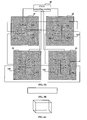
- the computer system includes at least two nodes, wherein, as shown in Fig. 1 , the at least two nodes each include a selecting module 11 and a CPU 12, inputs Input 1,... Input N to the selecting module 11 are clock src of the current node and clock output from the other node, and an output terminal (output) thereof is connected to the CPU 12 and an input terminal of the selecting module of the other node.
- the computer system further includes a clock controlling module 13, whose output terminal is connected to the control terminal of the selecting module to control the clocks output from the output terminals of the at least two nodes to be the same clock.
- the two nodes are directly connected to each other.
- the output terminal of selecting module 211 in node 21 is directly connected to the input terminal of selecting module 221 in node 22, and the output terminal of selecting module 221 in node 22 is connected to the input terminal of selecting module 211 in node 21.
- the other inputs to the selecting modules are clocks src of their own nodes.
- the output terminal of selecting module 211 in node 21 is connected to CPU 212 of the current node, and the output terminal of selecting module 221 in node 22 is connected to CPU 222 of the current node.
- Nodes 21 and 22 are connected in a bidirectional way, one of the connections may be closed in use, and the closed connection is initiated when the connection in use becomes abnormal.
- connection mode among them is similar to that shown in Fig. 2 , that is, the four nodes are connected to one another via respective selecting modules into a loop, and inputs to the selecting module of each node are clock of the current node and outputs from the selecting modules of the two nodes connected thereto.
- the computer system has four nodes, namely node 31, node 32, node 33 and node 34, and the selecting modules of the four nodes are sequentially connected into a loop, as shown in Fig. 3B .
- the output terminal of selecting module 311 is connected to the input terminals of selecting module 321 in node 32 and selecting module 341 in node 34, and connected to CPU 312 of the current node;
- the output terminal of selecting module 321 is connected to the input terminals of selecting module 311 in node 31 and selecting module 331 in node 33, and connected to CPU 332 of the current node;
- the output terminal of selecting module 331 is connected to the input terminals of selecting module 321 in node 32 and selecting module 341 in node 34, and connected to CPU 322 of the current node;
- the output terminal of selecting module 341 is connected to the input terminals of selecting module 311 in node 31 and selecting module 331 in node 33, and connected to CPU 342 of the current node.
- the control terminals of all the selecting modules are connected to the clock controlling module 35, under control of which all nodes select a clock source src of the one identical node as a common clock source.
- the connection between any two nodes is bidirectional connection - that is to say, there are two connection channels, namely clock channels, between two connected nodes; the uninitiated connection channel should be closed. When the clock channel in use becomes abnormal, a clock channel is reselected according to the normal status of the clock channels.
- the eight nodes are located at various vertices of a cuboid, four nodes within various surfaces of the cuboid are cross connected to one another via selecting modules or any two adjacent nodes are connected to one another via selecting modules, and eventually each node is connected to other three nodes via selecting modules.
- the four nodes at various surfaces of the cuboid are sequentially connected via selecting modules into a loop, and connection of the loop is similar to that shown in Fig. 3A .
- Each node is connected to three nodes via selecting modules, and the connection between any two nodes is bidirectional connection - that is to say, there are two connection channels, namely clock channels, between two connected nodes.
- every eight nodes are located at various vertices of a cuboid, four nodes within each surface of the cuboid are cross connected to one another via selecting modules or connected sequentially one after the other via selecting modules, and each node is connected to 3+n nodes via selecting modules. Connection of the cuboid is similar to that shown in Fig. 4A . Nodes at the same positions on the cuboids are connected via selecting modules, and inputs to the selecting module of each node are clock of the current node and outputs from the selecting modules of the 3+n nodes connected thereto, wherein n is a natural number.
- a structure as shown in Fig. 4B is obtained after connection
- a structure as shown in Fig. 5 is obtained after connection.
- Node connections for computer systems with sixty-four nodes and one hundred and twenty-eight nodes are similar to those described above.
- Eight nodes are located at various vertices of a cuboid, and each node is connected to three adjacent nodes.
- every eight nodes connected by the mode mentioned above as a whole can also be regarded as one point, and then each point is connected to the other by the connection mode mentioned above.
- sixteen nodes are located at various vertices of two cuboids, and points at the same positions on the two cuboids are then connected. And so on, connections of thirty-two nodes and sixty-four nodes could be realized, which will not be enumerated in this context.
- nodes with the most connections should be selected to form a partition as far as possible, for instance, two directly connected nodes are constructed as a partition system, or four nodes connected into a loop are constructed as a partition system.
- a computer system with n ⁇ 8 nodes it is also possible to construct 8 nodes connected into a cuboid as a partition system. This is because clock synchronization merely puts demand on the same partition system, while formation of the nodes with the most connections into a partition system can guarantee, to the maximum degree, that a substitute channel could be found in the case certain nodes in the partition system become abnormal, without affecting other partition systems.
- nodes pertaining to the same partition system in the computer system are directly or indirectly connected to one another, and the intermediate nodes of an indirect connection and the two end nodes of the indirect connection are located in the same partition system.
- nx8 nodes for example, eight nodes connected into a cuboid are constructed as a partition system.
- the partition system After partitioning of the computer system provided by the aforementioned embodiments, if the clock source is abnormal in a certain partition system, operation of the partition system will not be affected as long as there is a normal clock in that partition system. If a certain clock channel of the partition system becomes abnormal, nodes downstream of the abnormal clock channel can properly operate, the partition system can still normally operate as long as there is another normal channel. If a certain node of the partition system functions abnormally, after the abnormal node is removed, the partition system can still normally operate as long as the clocks of the remaining nodes can be interconnected by routing.
- Table 1 A clock relation routing table shown in the following Table 1 is generated according to the connection relations illustrated in Fig. 6 .
- Table 1 Clock Relation Connection Table Starting Point Finishing Point 0 1, 2, 6 1 0, 3, 7 2 0, 3, 5 3 1, 2, 4 4 3, 5, 6 5 2, 4, 7 6 0, 4, 7 7 1, 5, 6
- a 2P partition system is to be constructed, two directly connected nodes are selected to form a partition system.
- various node clocks in a partition system are all provided by the nodes within the partition, so as to prevent partition systems from interfering with each other. If all node clocks of a certain partition system become abnormal, it is possible to provide all nodes of the partition system with clocks by a node of a connected partition system, but whether clocks of the partition system normally operate or not is then controlled by the other partition. Under such a circumstance, it is possible to separate the two nodes from each other to perform partitioning again, and to form two independent 2P partitions with other connected nodes respectively.
- the fault-tolerant probability is highest when four nodes connected up and down or front and back with one another into a loop are randomly selected to form a partition system.
- the partition should be reasonably constructed according to the aforementioned partitioning principle to ensure that all partition systems can normally operate.
- a 6P partition system is to be constructed, four nodes are first selected according to the mode in which 4P partition is constructed, and then any two adjacent nodes capable of forming 2P, namely two directly connected nodes, are randomly selected to construct a 6P partition system together with the constructed 4P partition system.
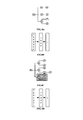
- the configuring flow includes the following steps.
- Step 701 - constructing a clock relation connection table according to clock connection modes, as shown in Table 1, each row of Table 1 represents one tier, and each tier has a starting point and a finishing point.
- the connections between the starting point and the finishing point are bidirectional connection channels, specifically, there is not only a connection channel from the starting point to the finishing point, but also a connection channel from the finishing point to the starting point - for instance, in Table 1, node 0 is the starting point and node 1 is the finishing point in the second row, whereas node 1 is the starting point and node 0 is the finishing point in the third row.
- the subsequent steps are performed on repetitive direct or indirect connections for nodes such that the connections are simplified as unidirectional and non-repetitive connections, and directed to selecting from the bidirectional connection channels between directly connected nodes one connection channel as a clock channel between the directly connected nodes and another connection channel as backup, such that clock configuration could be performed again for the partition system in case of clock abnormality, channel abnormality or node abnormality.
- Step 702 detecting normality of each node clock.
- Step 703 selecting and initiating a clock source. Specifically, a normal node clock is selected as the clock source, among main node clock, node clock of the current partition, and node clock of other partitions in an order of main node clock ⁇ node clock of the current partition ⁇ node clock of other partitions, and this node clock is initiated.
- clock of the main node is selected as the clock source, that is to say, if there is no abnormality occurred to it, the clock of the main node is selected; if there is abnormality, the clock of a node directly connected to the main node in the same partition is selected as the clock source.
- node 0 is the main node, and abnormality of the clock at node 0 is detected.
- Step 705 determining whether all nodes in the partition system have already been added to the clock relation routing table. If all nodes have been added to the clock relation routing table, the clock configuration is completed, otherwise Step 706 is executed.
- Step 706 determining whether all nodes directly connected to the starting point of the current tier in the partition system have already been added to the clock relation routing table. If they are present in the clock relation routing table, Step 709 is executed, otherwise Step 707 is executed.
- Step 709 - determining whether there are nodes of the same level as the starting point of the current tier, for example, the starting point of the current is N hops away from the clock source, and certain nodes are also N hops away from the clock source.
- Step 712 is executed, otherwise Step 710 is executed.
- Step 711 setting the first found starting point of the next tier as the starting point of the current tier, and continuing to execute Step 705.
- Step 712 selecting this node as the starting point of the current tier, and continuing to execute Step 705.
- node 1, node 2 and node 6 are taken as the starting points of the next tier to determine whether the connection channels between node 1 and nodes 3 and 7 are normal, where node 3 and node 7 are nodes that are directly connected to node 1. If the connection channels between node 1 and nodes 3 and 7 are normal, the connection channel in a direction from node 1 to nodes 3 is initiated or selected as the clock channel between node 1 and node 3, and the connection channel in a direction from node 1 to nodes 7 is initiated or selected as the clock channel between node 1 and node 7, and node 1, node 3 and node 7 are added to the clock relation routing table as one tier, with node 1 being the starting point of the tier and node 3 and node 7 being the finishing points of the tier, as shown in Table 4. Table 4 Starting Point Finishing Point Node 0 Node 1, Node 2, Node 6 Node 1 Node 3, Node 7
- connection channels between the node 2 and node 5, which is directly connected to node 2 are normal; if the connection channels between node 2 and node 5 are normal, the connection channel in a direction from node 2 to node 5 is taken as the clock channel between node 2 and node 5, and node 2 and node 5 are added to the clock relation routing table as one tier, with node 2 being the starting point of the tier and node 5 being the finishing point of the tier, as shown in Table 5.
- connection channels between node 6 and node 4, which is directly connected to node 6, are normal; if the connection channels between node 6 and node 4 are normal, the connection channel in a direction from node 6 to node 4 is taken as the clock channel between node 6 and node 4, and node 6 and node 4 are added to the clock relation routing table as one tier, with node 6 being the starting point of the tier and node 4 being the finishing point of the tier, as shown in Table 6.
- Fig. 9 is a view schematically illustrating another clock connection of the eight nodes in the computer system shown in Fig. 6 . It is also expressed as a cuboid, with up and down, front and back, and left to right sequential loops, while no crossing is present.
- the clock relation connection table thereof is shown in Table 7.
- the clock connection modes among the nodes in the aforementioned device and method embodiments can also be applied to quick path interconnect (QPI) of partitions, and can be applied to similar connections among nodes in other systems.
- QPI quick path interconnect
Landscapes
- Engineering & Computer Science (AREA)
- Theoretical Computer Science (AREA)
- Physics & Mathematics (AREA)
- General Engineering & Computer Science (AREA)
- General Physics & Mathematics (AREA)
- Quality & Reliability (AREA)
- Hardware Redundancy (AREA)
Claims (6)
- Computersystem, das Folgendes aufweist:mindestens zwei Knoten, wobei jeder der mindestens zwei Knoten (21, 22) ein Auswahlmodul (211, 221) und eine CPU (212, 222) aufweist, wobei die Eingaben der Auswahlmodule (211, 221) einen Takt eines lokalen Knotens und einen Takt aufweisen, der aus einem anderen Knoten ausgegeben wird, und ein Ausgangsanschluss der Auswahlmodule (211, 221) mit der CPU (212, 222) und einem Eingangsanschluss des Auswahlmoduls (211, 221) des anderen Knotens verbunden ist;wobei das Computersystem ferner ein Taktsteuermodul (213) aufweist, wobei ein Ausgangsanschluss des Taktsteuermoduls (213) mit einem Steueranschluss des Auswahlmoduls (211, 221) von jedem der mindestens zwei Knoten (21, 22) verbunden ist, um die Takte der mindestens zwei Knoten so zu steuern, dass sie derselbe Takt sind,wobei das Taktsteuermodul (213) die Auswahlmodule der mindestens zwei Knoten so steuert, dass sie einen Takt von einem der mindestens zwei Knoten als eine gemeinsame Taktquelle für die mindestens zwei Knoten auswählen, und wenn der Takt des ausgewählten Knotens anormal wird, das Taktsteuermodul (213) die Auswahlmodule (211, 221) des Rests der mindestens zwei Knoten so steuert, dass sie eine andere verfügbare gemeinsame Taktquelle entsprechend Taktkanälen auswählen, die in einer Taktbeziehungs-Verbindungstabelle aufgezeichnet sind, so dass der Rest der mindestens zwei Knoten mit demselben Takt versehen wird, wobei der Taktkanal ein Weg von einem der mindestens zwei Knoten zu irgendeinem des Rests der mindestens zwei Knoten ist.
- Computersystem nach Anspruch 1, wobei die mindestens zwei Knoten vier Knoten sind, die miteinander durch Auswahlmodule (211, 221) in einer Schleife verbunden sind, wobei die Eingaben in das Auswahlmodul (211, 221) jedes Knotens den Takt des Knotens und Ausgaben aus den Auswahlmodulen (211, 221) der damit verbundenen zwei Knoten aufweisen.
- Computersystem nach Anspruch 1, wobei die mindestens zwei Knoten acht Knoten sind, die jeweils an jedem Eckpunkt eines Quaders angeordnet sind, wobei die vier Knoten innerhalb verschiedener Oberflächen des Quaders über Auswahlmodule (211, 221) miteinander kreuzverbunden sind oder alle zwei benachbarten Knoten miteinander über Auswahlmodule (211, 221) verbunden sind, jeder Knoten mit drei Knoten über Auswahlmodule (211, 221) verbunden ist, und Eingaben in das Auswahlmodul (211, 221) jedes Knotens den Takt des Knotens und die Ausgaben aus den Auswahlmodulen (211, 221) der damit verbundenen drei Knoten aufweisen.
- Computersystem nach Anspruch 1, wobei die mindestens zwei Knoten nx8 Knoten sind, wobei alle acht Knoten jeweils an jedem Eckpunkt eines Quaders angeordnet sind, vier Knoten innerhalb jeder Oberfläche des Quaders über Auswahlmodule (211, 221) miteinander kreuzverbunden sind oder sequentiell einer nach dem anderen über Auswahlmodule (211, 221) verbunden sind, jeder Knoten über Auswahlmodule (211, 221) mit 3+n Knoten verbunden ist, Knoten an denselben Positionen an jedem Quader über Auswahlmodule (211, 221) verbunden sind, und Eingaben in das Auswahlmodul (211, 221) jedes Knotens den Takt des Knotens und die Ausgaben aus den Auswahlmodulen (211, 221) der damit verbundenen 3+n Knoten aufweisen, wobei n eine natürliche Zahl ist, die größer als 0 ist.
- Computersystem nach einem der Ansprüche 2 bis 4, wobei Knoten, die direkt oder indirekt miteinander verbunden sind, ein Partitionssystem im Computersystem bilden, und Zwischenknoten auf einem Taktkanal und Knoten an beiden Enden des Taktkanals im identischen Partitionssystem angeordnet sind.
- Computersystem nach einem der Ansprüche 1 bis 4, wobei eine Verbindung zwischen dem Ausgangsanschluss des Auswahlmoduls (211, 221) und dem Eingangsanschluss des Auswahlmoduls (211, 221) eines anderen Knotens über ein CPU-Verbindungskabel erzielt wird.
Applications Claiming Priority (1)
| Application Number | Priority Date | Filing Date | Title |
|---|---|---|---|
| PCT/CN2011/077625 WO2012106929A1 (zh) | 2011-07-26 | 2011-07-26 | 计算机系统及其配置时钟的方法 |
Publications (3)
| Publication Number | Publication Date |
|---|---|
| EP2573643A1 EP2573643A1 (de) | 2013-03-27 |
| EP2573643A4 EP2573643A4 (de) | 2014-08-27 |
| EP2573643B1 true EP2573643B1 (de) | 2015-09-23 |
Family
ID=45429409
Family Applications (1)
| Application Number | Title | Priority Date | Filing Date |
|---|---|---|---|
| EP11858207.1A Active EP2573643B1 (de) | 2011-07-26 | 2011-07-26 | Computersystem und uhrenkonfigurationsverfahren dafür |
Country Status (4)
| Country | Link |
|---|---|
| US (1) | US9026835B2 (de) |
| EP (1) | EP2573643B1 (de) |
| CN (1) | CN102317885B (de) |
| WO (1) | WO2012106929A1 (de) |
Families Citing this family (2)
| Publication number | Priority date | Publication date | Assignee | Title |
|---|---|---|---|---|
| EP2573643B1 (de) | 2011-07-26 | 2015-09-23 | Huawei Technologies Co., Ltd. | Computersystem und uhrenkonfigurationsverfahren dafür |
| CN105022715A (zh) * | 2015-07-08 | 2015-11-04 | 浪潮(北京)电子信息产业有限公司 | 一种服务器背板互连方法和系统 |
Family Cites Families (24)
| Publication number | Priority date | Publication date | Assignee | Title |
|---|---|---|---|---|
| US4239982A (en) * | 1978-06-14 | 1980-12-16 | The Charles Stark Draper Laboratory, Inc. | Fault-tolerant clock system |
| GB2227341A (en) * | 1989-01-18 | 1990-07-25 | Intel Corp | Message routing in a multiprocessor computer system |
| US5249206A (en) * | 1989-08-11 | 1993-09-28 | International Business Machines Corporation | Fault-tolerant clock for multicomputer complex |
| US5404363A (en) * | 1991-11-27 | 1995-04-04 | Honeywell Inc. | Two-fail-operational fault-tolerant multiple clock system |
| JPH0778039A (ja) * | 1993-09-08 | 1995-03-20 | Fujitsu Ltd | クロック選択制御方式 |
| US5758132A (en) * | 1995-03-29 | 1998-05-26 | Telefonaktiebolaget Lm Ericsson | Clock control system and method using circuitry operating at lower clock frequency for selecting and synchronizing the switching of higher frequency clock signals |
| SE504920C2 (sv) * | 1995-09-29 | 1997-05-26 | Ericsson Telefon Ab L M | Förfarande och system för redundant klockdistribution till telekommunikationsutrustningar i vilka byte av vald klocksignal bland de inkommande klocksignalerna ständigt sker |
| JPH11103312A (ja) * | 1997-09-26 | 1999-04-13 | Mitsubishi Electric Corp | ネットワークのクロック同期管理装置 |
| US6754171B1 (en) * | 2000-05-18 | 2004-06-22 | Enterasys Networks, Inc. | Method and system for distributed clock failure protection in a packet switched network |
| US7650434B2 (en) * | 2001-02-24 | 2010-01-19 | International Business Machines Corporation | Global tree network for computing structures enabling global processing operations |
| US6592449B2 (en) | 2001-02-24 | 2003-07-15 | International Business Machines Corporation | Smart fan modules and system |
| CN1281005C (zh) * | 2001-06-29 | 2006-10-18 | 中兴通讯股份有限公司 | 光同步数字传送网时钟源选择控制方法 |
| US7089442B2 (en) * | 2003-02-07 | 2006-08-08 | Rambus Inc. | Fault-tolerant clock generator |
| US7230468B2 (en) * | 2004-03-10 | 2007-06-12 | Hewlett-Packard Development Company, L.P. | Systems and methods for providing distributed control signal redundancy among electronic circuits |
| US7602869B2 (en) | 2005-07-29 | 2009-10-13 | International Business Machines Corporation | Methods and apparatus for clock synchronization and data recovery in a receiver |
| US7562247B2 (en) * | 2006-05-16 | 2009-07-14 | International Business Machines Corporation | Providing independent clock failover for scalable blade servers |
| US7870413B2 (en) * | 2006-08-15 | 2011-01-11 | Mitac International Corp. | Synchronization clocking scheme for small scalable multi-processor system |
| CN101192913B (zh) * | 2007-08-08 | 2010-12-08 | 中兴通讯股份有限公司 | 一种在光传送网络完成时钟同步和时钟倒换的系统和方法 |
| CN100525212C (zh) * | 2007-08-10 | 2009-08-05 | 中控科技集团有限公司 | 网络时钟同步的方法及系统 |
| US8161311B2 (en) * | 2007-08-23 | 2012-04-17 | Stratus Technologies Bermuda Ltd | Apparatus and method for redundant and spread spectrum clocking |
| US8239704B2 (en) * | 2009-06-12 | 2012-08-07 | Cray Inc. | Global clock via embedded spanning tree |
| WO2011014178A1 (en) * | 2009-07-31 | 2011-02-03 | Hewlett-Packard Development Company, L.P. | Providing fault-tolerant spread spectrum clock signals in a system |
| US8212601B2 (en) * | 2010-10-29 | 2012-07-03 | Netgear, Inc. | Method and apparatus for providing system clock failover |
| EP2573643B1 (de) * | 2011-07-26 | 2015-09-23 | Huawei Technologies Co., Ltd. | Computersystem und uhrenkonfigurationsverfahren dafür |
-
2011
- 2011-07-26 EP EP11858207.1A patent/EP2573643B1/de active Active
- 2011-07-26 CN CN201180001193.7A patent/CN102317885B/zh active Active
- 2011-07-26 WO PCT/CN2011/077625 patent/WO2012106929A1/zh not_active Ceased
-
2012
- 2012-12-17 US US13/717,205 patent/US9026835B2/en active Active
Also Published As
| Publication number | Publication date |
|---|---|
| US20130103971A1 (en) | 2013-04-25 |
| EP2573643A4 (de) | 2014-08-27 |
| EP2573643A1 (de) | 2013-03-27 |
| CN102317885A (zh) | 2012-01-11 |
| CN102317885B (zh) | 2014-05-07 |
| US9026835B2 (en) | 2015-05-05 |
| WO2012106929A1 (zh) | 2012-08-16 |
Similar Documents
| Publication | Publication Date | Title |
|---|---|---|
| JP5660798B2 (ja) | 情報処理装置 | |
| KR101992508B1 (ko) | 고가용성 클러스터에서의 스플릿브레인 방지 페일오버 | |
| US20140361806A1 (en) | Configurable Vertical Integration | |
| CN102939591A (zh) | 用于锁步同步的系统和方法 | |
| EP2573643B1 (de) | Computersystem und uhrenkonfigurationsverfahren dafür | |
| KR20190099683A (ko) | 분산형 소프트웨어 정의 네트워킹 방법 및 장치 | |
| JP2009151629A (ja) | ノードシステム、サーバ切換え方法、サーバ装置、データ引き継ぎ方法、およびプログラム | |
| CN112231142A (zh) | 系统备份恢复方法、装置、计算机设备和存储介质 | |
| US11695856B2 (en) | Scheduling solution configuration method and apparatus, computer readable storage medium thereof, and computer device | |
| US7103639B2 (en) | Method and apparatus for processing unit synchronization for scalable parallel processing | |
| JP6889138B2 (ja) | 格納装置及び格納方法 | |
| US10516625B2 (en) | Network entities on ring networks | |
| JP2003009194A (ja) | 光クロスコネクト装置並びにその制御装置及び方法 | |
| CN119742792A (zh) | 一种电力信息物理系统配置方法、装置、设备及存储介质 | |
| CN114546978B (zh) | 一种存储集群的位图管理方法、系统、设备以及介质 | |
| CN115858679A (zh) | 一种数据中心之间的数据同步方法、装置、设备及介质 | |
| US9118546B2 (en) | Data forwarding method and router | |
| JP2602421B2 (ja) | クロック受信分配システム | |
| JP7358819B2 (ja) | Ioモジュール二重化制御装置及び方法 | |
| US6591030B2 (en) | Method of mirror layout of multi-level optical switch | |
| JP7120599B2 (ja) | 情報処理システム及び制御方法 | |
| JP2839664B2 (ja) | 計算機システム | |
| CN120811871A (zh) | 光板面板口状态管理方法及机框设备 | |
| CN121257770A (zh) | 应用于分布式训练系统的训练容错方法、装置及芯片产品 | |
| Prajeesh et al. | Implementation of human endocrine cell structure on FPGA for self-healing advanced digital system |
Legal Events
| Date | Code | Title | Description |
|---|---|---|---|
| PUAI | Public reference made under article 153(3) epc to a published international application that has entered the european phase |
Free format text: ORIGINAL CODE: 0009012 |
|
| 17P | Request for examination filed |
Effective date: 20121219 |
|
| AK | Designated contracting states |
Kind code of ref document: A1 Designated state(s): AL AT BE BG CH CY CZ DE DK EE ES FI FR GB GR HR HU IE IS IT LI LT LU LV MC MK MT NL NO PL PT RO RS SE SI SK SM TR |
|
| A4 | Supplementary search report drawn up and despatched |
Effective date: 20140730 |
|
| RIC1 | Information provided on ipc code assigned before grant |
Ipc: G06F 11/16 20060101ALI20140724BHEP Ipc: G06F 1/12 20060101AFI20140724BHEP Ipc: G06F 11/20 20060101ALN20140724BHEP |
|
| DAX | Request for extension of the european patent (deleted) | ||
| GRAP | Despatch of communication of intention to grant a patent |
Free format text: ORIGINAL CODE: EPIDOSNIGR1 |
|
| RIC1 | Information provided on ipc code assigned before grant |
Ipc: G06F 1/12 20060101AFI20150323BHEP Ipc: G06F 11/20 20060101ALN20150323BHEP Ipc: G06F 11/16 20060101ALI20150323BHEP |
|
| RIC1 | Information provided on ipc code assigned before grant |
Ipc: G06F 1/12 20060101AFI20150330BHEP Ipc: G06F 11/20 20060101ALN20150330BHEP Ipc: G06F 11/16 20060101ALI20150330BHEP |
|
| INTG | Intention to grant announced |
Effective date: 20150415 |
|
| GRAS | Grant fee paid |
Free format text: ORIGINAL CODE: EPIDOSNIGR3 |
|
| GRAA | (expected) grant |
Free format text: ORIGINAL CODE: 0009210 |
|
| AK | Designated contracting states |
Kind code of ref document: B1 Designated state(s): AL AT BE BG CH CY CZ DE DK EE ES FI FR GB GR HR HU IE IS IT LI LT LU LV MC MK MT NL NO PL PT RO RS SE SI SK SM TR |
|
| REG | Reference to a national code |
Ref country code: GB Ref legal event code: FG4D |
|
| REG | Reference to a national code |
Ref country code: CH Ref legal event code: EP |
|
| REG | Reference to a national code |
Ref country code: AT Ref legal event code: REF Ref document number: 751572 Country of ref document: AT Kind code of ref document: T Effective date: 20151015 |
|
| REG | Reference to a national code |
Ref country code: IE Ref legal event code: FG4D |
|
| REG | Reference to a national code |
Ref country code: DE Ref legal event code: R096 Ref document number: 602011020094 Country of ref document: DE |
|
| REG | Reference to a national code |
Ref country code: SE Ref legal event code: TRGR |
|
| REG | Reference to a national code |
Ref country code: NL Ref legal event code: MP Effective date: 20150923 |
|
| PG25 | Lapsed in a contracting state [announced via postgrant information from national office to epo] |
Ref country code: GR Free format text: LAPSE BECAUSE OF FAILURE TO SUBMIT A TRANSLATION OF THE DESCRIPTION OR TO PAY THE FEE WITHIN THE PRESCRIBED TIME-LIMIT Effective date: 20151224 Ref country code: FI Free format text: LAPSE BECAUSE OF FAILURE TO SUBMIT A TRANSLATION OF THE DESCRIPTION OR TO PAY THE FEE WITHIN THE PRESCRIBED TIME-LIMIT Effective date: 20150923 Ref country code: NO Free format text: LAPSE BECAUSE OF FAILURE TO SUBMIT A TRANSLATION OF THE DESCRIPTION OR TO PAY THE FEE WITHIN THE PRESCRIBED TIME-LIMIT Effective date: 20151223 Ref country code: LV Free format text: LAPSE BECAUSE OF FAILURE TO SUBMIT A TRANSLATION OF THE DESCRIPTION OR TO PAY THE FEE WITHIN THE PRESCRIBED TIME-LIMIT Effective date: 20150923 Ref country code: LT Free format text: LAPSE BECAUSE OF FAILURE TO SUBMIT A TRANSLATION OF THE DESCRIPTION OR TO PAY THE FEE WITHIN THE PRESCRIBED TIME-LIMIT Effective date: 20150923 |
|
| REG | Reference to a national code |
Ref country code: LT Ref legal event code: MG4D |
|
| REG | Reference to a national code |
Ref country code: AT Ref legal event code: MK05 Ref document number: 751572 Country of ref document: AT Kind code of ref document: T Effective date: 20150923 |
|
| PG25 | Lapsed in a contracting state [announced via postgrant information from national office to epo] |
Ref country code: HR Free format text: LAPSE BECAUSE OF FAILURE TO SUBMIT A TRANSLATION OF THE DESCRIPTION OR TO PAY THE FEE WITHIN THE PRESCRIBED TIME-LIMIT Effective date: 20150923 Ref country code: RS Free format text: LAPSE BECAUSE OF FAILURE TO SUBMIT A TRANSLATION OF THE DESCRIPTION OR TO PAY THE FEE WITHIN THE PRESCRIBED TIME-LIMIT Effective date: 20150923 |
|
| PG25 | Lapsed in a contracting state [announced via postgrant information from national office to epo] |
Ref country code: NL Free format text: LAPSE BECAUSE OF FAILURE TO SUBMIT A TRANSLATION OF THE DESCRIPTION OR TO PAY THE FEE WITHIN THE PRESCRIBED TIME-LIMIT Effective date: 20150923 |
|
| PG25 | Lapsed in a contracting state [announced via postgrant information from national office to epo] |
Ref country code: ES Free format text: LAPSE BECAUSE OF FAILURE TO SUBMIT A TRANSLATION OF THE DESCRIPTION OR TO PAY THE FEE WITHIN THE PRESCRIBED TIME-LIMIT Effective date: 20150923 Ref country code: CZ Free format text: LAPSE BECAUSE OF FAILURE TO SUBMIT A TRANSLATION OF THE DESCRIPTION OR TO PAY THE FEE WITHIN THE PRESCRIBED TIME-LIMIT Effective date: 20150923 Ref country code: EE Free format text: LAPSE BECAUSE OF FAILURE TO SUBMIT A TRANSLATION OF THE DESCRIPTION OR TO PAY THE FEE WITHIN THE PRESCRIBED TIME-LIMIT Effective date: 20150923 Ref country code: IS Free format text: LAPSE BECAUSE OF FAILURE TO SUBMIT A TRANSLATION OF THE DESCRIPTION OR TO PAY THE FEE WITHIN THE PRESCRIBED TIME-LIMIT Effective date: 20160123 Ref country code: SK Free format text: LAPSE BECAUSE OF FAILURE TO SUBMIT A TRANSLATION OF THE DESCRIPTION OR TO PAY THE FEE WITHIN THE PRESCRIBED TIME-LIMIT Effective date: 20150923 Ref country code: IT Free format text: LAPSE BECAUSE OF FAILURE TO SUBMIT A TRANSLATION OF THE DESCRIPTION OR TO PAY THE FEE WITHIN THE PRESCRIBED TIME-LIMIT Effective date: 20150923 |
|
| PG25 | Lapsed in a contracting state [announced via postgrant information from national office to epo] |
Ref country code: PT Free format text: LAPSE BECAUSE OF FAILURE TO SUBMIT A TRANSLATION OF THE DESCRIPTION OR TO PAY THE FEE WITHIN THE PRESCRIBED TIME-LIMIT Effective date: 20160125 Ref country code: AT Free format text: LAPSE BECAUSE OF FAILURE TO SUBMIT A TRANSLATION OF THE DESCRIPTION OR TO PAY THE FEE WITHIN THE PRESCRIBED TIME-LIMIT Effective date: 20150923 Ref country code: PL Free format text: LAPSE BECAUSE OF FAILURE TO SUBMIT A TRANSLATION OF THE DESCRIPTION OR TO PAY THE FEE WITHIN THE PRESCRIBED TIME-LIMIT Effective date: 20150923 Ref country code: RO Free format text: LAPSE BECAUSE OF FAILURE TO SUBMIT A TRANSLATION OF THE DESCRIPTION OR TO PAY THE FEE WITHIN THE PRESCRIBED TIME-LIMIT Effective date: 20150923 |
|
| REG | Reference to a national code |
Ref country code: DE Ref legal event code: R097 Ref document number: 602011020094 Country of ref document: DE |
|
| PLBE | No opposition filed within time limit |
Free format text: ORIGINAL CODE: 0009261 |
|
| STAA | Information on the status of an ep patent application or granted ep patent |
Free format text: STATUS: NO OPPOSITION FILED WITHIN TIME LIMIT |
|
| 26N | No opposition filed |
Effective date: 20160624 |
|
| PG25 | Lapsed in a contracting state [announced via postgrant information from national office to epo] |
Ref country code: DK Free format text: LAPSE BECAUSE OF FAILURE TO SUBMIT A TRANSLATION OF THE DESCRIPTION OR TO PAY THE FEE WITHIN THE PRESCRIBED TIME-LIMIT Effective date: 20150923 |
|
| PG25 | Lapsed in a contracting state [announced via postgrant information from national office to epo] |
Ref country code: SI Free format text: LAPSE BECAUSE OF FAILURE TO SUBMIT A TRANSLATION OF THE DESCRIPTION OR TO PAY THE FEE WITHIN THE PRESCRIBED TIME-LIMIT Effective date: 20150923 |
|
| PG25 | Lapsed in a contracting state [announced via postgrant information from national office to epo] |
Ref country code: BE Free format text: LAPSE BECAUSE OF FAILURE TO SUBMIT A TRANSLATION OF THE DESCRIPTION OR TO PAY THE FEE WITHIN THE PRESCRIBED TIME-LIMIT Effective date: 20150923 |
|
| REG | Reference to a national code |
Ref country code: CH Ref legal event code: PL |
|
| PG25 | Lapsed in a contracting state [announced via postgrant information from national office to epo] |
Ref country code: MC Free format text: LAPSE BECAUSE OF FAILURE TO SUBMIT A TRANSLATION OF THE DESCRIPTION OR TO PAY THE FEE WITHIN THE PRESCRIBED TIME-LIMIT Effective date: 20150923 |
|
| PG25 | Lapsed in a contracting state [announced via postgrant information from national office to epo] |
Ref country code: CH Free format text: LAPSE BECAUSE OF NON-PAYMENT OF DUE FEES Effective date: 20160731 Ref country code: FR Free format text: LAPSE BECAUSE OF NON-PAYMENT OF DUE FEES Effective date: 20160801 Ref country code: LI Free format text: LAPSE BECAUSE OF NON-PAYMENT OF DUE FEES Effective date: 20160731 |
|
| REG | Reference to a national code |
Ref country code: FR Ref legal event code: ST Effective date: 20170331 |
|
| REG | Reference to a national code |
Ref country code: IE Ref legal event code: MM4A |
|
| PG25 | Lapsed in a contracting state [announced via postgrant information from national office to epo] |
Ref country code: IE Free format text: LAPSE BECAUSE OF NON-PAYMENT OF DUE FEES Effective date: 20160726 |
|
| PG25 | Lapsed in a contracting state [announced via postgrant information from national office to epo] |
Ref country code: LU Free format text: LAPSE BECAUSE OF NON-PAYMENT OF DUE FEES Effective date: 20160726 |
|
| PG25 | Lapsed in a contracting state [announced via postgrant information from national office to epo] |
Ref country code: CY Free format text: LAPSE BECAUSE OF FAILURE TO SUBMIT A TRANSLATION OF THE DESCRIPTION OR TO PAY THE FEE WITHIN THE PRESCRIBED TIME-LIMIT Effective date: 20150923 Ref country code: SM Free format text: LAPSE BECAUSE OF FAILURE TO SUBMIT A TRANSLATION OF THE DESCRIPTION OR TO PAY THE FEE WITHIN THE PRESCRIBED TIME-LIMIT Effective date: 20150923 Ref country code: HU Free format text: LAPSE BECAUSE OF FAILURE TO SUBMIT A TRANSLATION OF THE DESCRIPTION OR TO PAY THE FEE WITHIN THE PRESCRIBED TIME-LIMIT; INVALID AB INITIO Effective date: 20110726 |
|
| PG25 | Lapsed in a contracting state [announced via postgrant information from national office to epo] |
Ref country code: MT Free format text: LAPSE BECAUSE OF NON-PAYMENT OF DUE FEES Effective date: 20160731 Ref country code: MK Free format text: LAPSE BECAUSE OF FAILURE TO SUBMIT A TRANSLATION OF THE DESCRIPTION OR TO PAY THE FEE WITHIN THE PRESCRIBED TIME-LIMIT Effective date: 20150923 Ref country code: TR Free format text: LAPSE BECAUSE OF FAILURE TO SUBMIT A TRANSLATION OF THE DESCRIPTION OR TO PAY THE FEE WITHIN THE PRESCRIBED TIME-LIMIT Effective date: 20150923 |
|
| PG25 | Lapsed in a contracting state [announced via postgrant information from national office to epo] |
Ref country code: BG Free format text: LAPSE BECAUSE OF FAILURE TO SUBMIT A TRANSLATION OF THE DESCRIPTION OR TO PAY THE FEE WITHIN THE PRESCRIBED TIME-LIMIT Effective date: 20150923 |
|
| PG25 | Lapsed in a contracting state [announced via postgrant information from national office to epo] |
Ref country code: AL Free format text: LAPSE BECAUSE OF FAILURE TO SUBMIT A TRANSLATION OF THE DESCRIPTION OR TO PAY THE FEE WITHIN THE PRESCRIBED TIME-LIMIT Effective date: 20150923 |
|
| PGFP | Annual fee paid to national office [announced via postgrant information from national office to epo] |
Ref country code: GB Payment date: 20250605 Year of fee payment: 15 |
|
| PGFP | Annual fee paid to national office [announced via postgrant information from national office to epo] |
Ref country code: SE Payment date: 20250610 Year of fee payment: 15 |
|
| PGFP | Annual fee paid to national office [announced via postgrant information from national office to epo] |
Ref country code: DE Payment date: 20250604 Year of fee payment: 15 |