EP2573643B1 - Computer system and clock configuration method thereof - Google Patents
Computer system and clock configuration method thereof Download PDFInfo
- Publication number
- EP2573643B1 EP2573643B1 EP11858207.1A EP11858207A EP2573643B1 EP 2573643 B1 EP2573643 B1 EP 2573643B1 EP 11858207 A EP11858207 A EP 11858207A EP 2573643 B1 EP2573643 B1 EP 2573643B1
- Authority
- EP
- European Patent Office
- Prior art keywords
- nodes
- node
- clock
- selecting
- computer system
- Prior art date
- Legal status (The legal status is an assumption and is not a legal conclusion. Google has not performed a legal analysis and makes no representation as to the accuracy of the status listed.)
- Active
Links
- 238000000034 method Methods 0.000 title description 13
- 238000005192 partition Methods 0.000 claims description 93
- 230000002159 abnormal effect Effects 0.000 claims description 26
- 230000005856 abnormality Effects 0.000 description 7
- 230000002457 bidirectional effect Effects 0.000 description 6
- 238000000638 solvent extraction Methods 0.000 description 6
- 238000005516 engineering process Methods 0.000 description 5
- 230000008569 process Effects 0.000 description 3
- 235000008694 Humulus lupulus Nutrition 0.000 description 2
- 230000000977 initiatory effect Effects 0.000 description 2
- 230000003252 repetitive effect Effects 0.000 description 2
- 230000001360 synchronised effect Effects 0.000 description 2
- 230000015572 biosynthetic process Effects 0.000 description 1
- 230000008859 change Effects 0.000 description 1
- 238000010276 construction Methods 0.000 description 1
- 230000002950 deficient Effects 0.000 description 1
- 230000006870 function Effects 0.000 description 1
- 230000002452 interceptive effect Effects 0.000 description 1
- 230000007257 malfunction Effects 0.000 description 1
- 230000004048 modification Effects 0.000 description 1
- 238000012986 modification Methods 0.000 description 1
- 230000003287 optical effect Effects 0.000 description 1
- 230000004044 response Effects 0.000 description 1
- 238000006467 substitution reaction Methods 0.000 description 1
Images


Classifications
-
- G—PHYSICS
- G06—COMPUTING; CALCULATING OR COUNTING
- G06F—ELECTRIC DIGITAL DATA PROCESSING
- G06F1/00—Details not covered by groups G06F3/00 - G06F13/00 and G06F21/00
- G06F1/04—Generating or distributing clock signals or signals derived directly therefrom
-
- G—PHYSICS
- G06—COMPUTING; CALCULATING OR COUNTING
- G06F—ELECTRIC DIGITAL DATA PROCESSING
- G06F1/00—Details not covered by groups G06F3/00 - G06F13/00 and G06F21/00
- G06F1/04—Generating or distributing clock signals or signals derived directly therefrom
- G06F1/12—Synchronisation of different clock signals provided by a plurality of clock generators
-
- G—PHYSICS
- G06—COMPUTING; CALCULATING OR COUNTING
- G06F—ELECTRIC DIGITAL DATA PROCESSING
- G06F11/00—Error detection; Error correction; Monitoring
- G06F11/07—Responding to the occurrence of a fault, e.g. fault tolerance
- G06F11/16—Error detection or correction of the data by redundancy in hardware
- G06F11/1604—Error detection or correction of the data by redundancy in hardware where the fault affects the clock signals of a processing unit and the redundancy is at or within the level of clock signal generation hardware
-
- G—PHYSICS
- G06—COMPUTING; CALCULATING OR COUNTING
- G06F—ELECTRIC DIGITAL DATA PROCESSING
- G06F11/00—Error detection; Error correction; Monitoring
- G06F11/07—Responding to the occurrence of a fault, e.g. fault tolerance
- G06F11/16—Error detection or correction of the data by redundancy in hardware
- G06F11/20—Error detection or correction of the data by redundancy in hardware using active fault-masking, e.g. by switching out faulty elements or by switching in spare elements
Definitions
- the present invention relates to computer system technology, and more particularly, to a computer system and a clock configuring method for achieving node clock synchronization of an identical partition system in a computer system.
- such a computer system as a minicomputer requiring high computational and fault-tolerant performances consists of a plurality of different nodes, wherein the nodes are the smallest units of hard partition, each node can independently form a partition or can interconnect with other nodes to form a partition, and on each partition can run an independent operating system.
- the nodes are the smallest units of hard partition
- each node can independently form a partition or can interconnect with other nodes to form a partition, and on each partition can run an independent operating system.
- several independent nodes in the computer system form an integral whole, namely a partition system, via the CPU interconnection technology. Under this integral whole can run an operating system that may access to any valid device on the nodes pertaining to the partition.
- Each node in a partition system not only requires clocks, but also requires clocks of the same source. This is so because clocks are of great importance in digital circuits - once there is no clock, it would be entirely impossible for digital logic to properly operate. Moreover, if various nodes in a partition system did not use clocks of the same source, it would also be impossible for the entire partition to normally operate.
- the partition system makes use of a single clock synchronization scheme to achieve clock synchronization in the partition system. That is to say, there is only one clock in a partition system to serve as the clock source for various nodes within the partition system, and the clock is either placed on a certain node of the partition system, or separated from the various nodes so as to be separately arranged.
- Embodiments of the present invention aim to provide a computer system and a clock configuring method for achieving node clock synchronization of an identical partition system in the computer system, so as to make it still possible to achieve synchronization of clocks of various nodes of the same partition system in the computer system during clock source failure within the partition system.
- a computer system which comprises at least two nodes, wherein each of the at least two nodes includes a selecting module and a CPU, inputs to the selecting module comprise clock of the local node and clock output from other node, and an output terminal of the selecting module is connected to the CPU and an input terminal of the selecting module of other node.
- the computer system further comprises a clock controlling module, whose output terminal is connected to a control terminal of the selecting module of each of the at least two nodes for controlling the clocks of the at least two nodes to be the same clock.
- the clock controlling module controls the selecting modules of the at least two nodes to select a clock of one of the at least two nodes as a common clock source for the at least two nodes, and when the clock of the selected node becomes abnormal, the clock controlling module controls the selecting modules of the rest of the at least two nodes to select another available common clock source according to clock channels recorded in a clock relation connection table such that the rest of the at least two nodes are provided with the same clock, the clock channel being a route from one of the at least two nodes to any of the rest of the at least two nodes.
- the computer system includes at least two nodes, wherein, as shown in Fig. 1 , the at least two nodes each include a selecting module 11 and a CPU 12, inputs Input 1,... Input N to the selecting module 11 are clock src of the current node and clock output from the other node, and an output terminal (output) thereof is connected to the CPU 12 and an input terminal of the selecting module of the other node.
- the computer system further includes a clock controlling module 13, whose output terminal is connected to the control terminal of the selecting module to control the clocks output from the output terminals of the at least two nodes to be the same clock.
- the two nodes are directly connected to each other.
- the output terminal of selecting module 211 in node 21 is directly connected to the input terminal of selecting module 221 in node 22, and the output terminal of selecting module 221 in node 22 is connected to the input terminal of selecting module 211 in node 21.
- the other inputs to the selecting modules are clocks src of their own nodes.
- the output terminal of selecting module 211 in node 21 is connected to CPU 212 of the current node, and the output terminal of selecting module 221 in node 22 is connected to CPU 222 of the current node.
- Nodes 21 and 22 are connected in a bidirectional way, one of the connections may be closed in use, and the closed connection is initiated when the connection in use becomes abnormal.
- connection mode among them is similar to that shown in Fig. 2 , that is, the four nodes are connected to one another via respective selecting modules into a loop, and inputs to the selecting module of each node are clock of the current node and outputs from the selecting modules of the two nodes connected thereto.
- the computer system has four nodes, namely node 31, node 32, node 33 and node 34, and the selecting modules of the four nodes are sequentially connected into a loop, as shown in Fig. 3B .
- the output terminal of selecting module 311 is connected to the input terminals of selecting module 321 in node 32 and selecting module 341 in node 34, and connected to CPU 312 of the current node;
- the output terminal of selecting module 321 is connected to the input terminals of selecting module 311 in node 31 and selecting module 331 in node 33, and connected to CPU 332 of the current node;
- the output terminal of selecting module 331 is connected to the input terminals of selecting module 321 in node 32 and selecting module 341 in node 34, and connected to CPU 322 of the current node;
- the output terminal of selecting module 341 is connected to the input terminals of selecting module 311 in node 31 and selecting module 331 in node 33, and connected to CPU 342 of the current node.
- the control terminals of all the selecting modules are connected to the clock controlling module 35, under control of which all nodes select a clock source src of the one identical node as a common clock source.
- the connection between any two nodes is bidirectional connection - that is to say, there are two connection channels, namely clock channels, between two connected nodes; the uninitiated connection channel should be closed. When the clock channel in use becomes abnormal, a clock channel is reselected according to the normal status of the clock channels.
- the eight nodes are located at various vertices of a cuboid, four nodes within various surfaces of the cuboid are cross connected to one another via selecting modules or any two adjacent nodes are connected to one another via selecting modules, and eventually each node is connected to other three nodes via selecting modules.
- the four nodes at various surfaces of the cuboid are sequentially connected via selecting modules into a loop, and connection of the loop is similar to that shown in Fig. 3A .
- Each node is connected to three nodes via selecting modules, and the connection between any two nodes is bidirectional connection - that is to say, there are two connection channels, namely clock channels, between two connected nodes.
- every eight nodes are located at various vertices of a cuboid, four nodes within each surface of the cuboid are cross connected to one another via selecting modules or connected sequentially one after the other via selecting modules, and each node is connected to 3+n nodes via selecting modules. Connection of the cuboid is similar to that shown in Fig. 4A . Nodes at the same positions on the cuboids are connected via selecting modules, and inputs to the selecting module of each node are clock of the current node and outputs from the selecting modules of the 3+n nodes connected thereto, wherein n is a natural number.
- a structure as shown in Fig. 4B is obtained after connection
- a structure as shown in Fig. 5 is obtained after connection.
- Node connections for computer systems with sixty-four nodes and one hundred and twenty-eight nodes are similar to those described above.
- Eight nodes are located at various vertices of a cuboid, and each node is connected to three adjacent nodes.
- every eight nodes connected by the mode mentioned above as a whole can also be regarded as one point, and then each point is connected to the other by the connection mode mentioned above.
- sixteen nodes are located at various vertices of two cuboids, and points at the same positions on the two cuboids are then connected. And so on, connections of thirty-two nodes and sixty-four nodes could be realized, which will not be enumerated in this context.
- nodes with the most connections should be selected to form a partition as far as possible, for instance, two directly connected nodes are constructed as a partition system, or four nodes connected into a loop are constructed as a partition system.
- a computer system with n ⁇ 8 nodes it is also possible to construct 8 nodes connected into a cuboid as a partition system. This is because clock synchronization merely puts demand on the same partition system, while formation of the nodes with the most connections into a partition system can guarantee, to the maximum degree, that a substitute channel could be found in the case certain nodes in the partition system become abnormal, without affecting other partition systems.
- nodes pertaining to the same partition system in the computer system are directly or indirectly connected to one another, and the intermediate nodes of an indirect connection and the two end nodes of the indirect connection are located in the same partition system.
- nx8 nodes for example, eight nodes connected into a cuboid are constructed as a partition system.
- the partition system After partitioning of the computer system provided by the aforementioned embodiments, if the clock source is abnormal in a certain partition system, operation of the partition system will not be affected as long as there is a normal clock in that partition system. If a certain clock channel of the partition system becomes abnormal, nodes downstream of the abnormal clock channel can properly operate, the partition system can still normally operate as long as there is another normal channel. If a certain node of the partition system functions abnormally, after the abnormal node is removed, the partition system can still normally operate as long as the clocks of the remaining nodes can be interconnected by routing.
- Table 1 A clock relation routing table shown in the following Table 1 is generated according to the connection relations illustrated in Fig. 6 .
- Table 1 Clock Relation Connection Table Starting Point Finishing Point 0 1, 2, 6 1 0, 3, 7 2 0, 3, 5 3 1, 2, 4 4 3, 5, 6 5 2, 4, 7 6 0, 4, 7 7 1, 5, 6
- a 2P partition system is to be constructed, two directly connected nodes are selected to form a partition system.
- various node clocks in a partition system are all provided by the nodes within the partition, so as to prevent partition systems from interfering with each other. If all node clocks of a certain partition system become abnormal, it is possible to provide all nodes of the partition system with clocks by a node of a connected partition system, but whether clocks of the partition system normally operate or not is then controlled by the other partition. Under such a circumstance, it is possible to separate the two nodes from each other to perform partitioning again, and to form two independent 2P partitions with other connected nodes respectively.
- the fault-tolerant probability is highest when four nodes connected up and down or front and back with one another into a loop are randomly selected to form a partition system.
- the partition should be reasonably constructed according to the aforementioned partitioning principle to ensure that all partition systems can normally operate.
- a 6P partition system is to be constructed, four nodes are first selected according to the mode in which 4P partition is constructed, and then any two adjacent nodes capable of forming 2P, namely two directly connected nodes, are randomly selected to construct a 6P partition system together with the constructed 4P partition system.
- the configuring flow includes the following steps.
- Step 701 - constructing a clock relation connection table according to clock connection modes, as shown in Table 1, each row of Table 1 represents one tier, and each tier has a starting point and a finishing point.
- the connections between the starting point and the finishing point are bidirectional connection channels, specifically, there is not only a connection channel from the starting point to the finishing point, but also a connection channel from the finishing point to the starting point - for instance, in Table 1, node 0 is the starting point and node 1 is the finishing point in the second row, whereas node 1 is the starting point and node 0 is the finishing point in the third row.
- the subsequent steps are performed on repetitive direct or indirect connections for nodes such that the connections are simplified as unidirectional and non-repetitive connections, and directed to selecting from the bidirectional connection channels between directly connected nodes one connection channel as a clock channel between the directly connected nodes and another connection channel as backup, such that clock configuration could be performed again for the partition system in case of clock abnormality, channel abnormality or node abnormality.
- Step 702 detecting normality of each node clock.
- Step 703 selecting and initiating a clock source. Specifically, a normal node clock is selected as the clock source, among main node clock, node clock of the current partition, and node clock of other partitions in an order of main node clock ⁇ node clock of the current partition ⁇ node clock of other partitions, and this node clock is initiated.
- clock of the main node is selected as the clock source, that is to say, if there is no abnormality occurred to it, the clock of the main node is selected; if there is abnormality, the clock of a node directly connected to the main node in the same partition is selected as the clock source.
- node 0 is the main node, and abnormality of the clock at node 0 is detected.
- Step 705 determining whether all nodes in the partition system have already been added to the clock relation routing table. If all nodes have been added to the clock relation routing table, the clock configuration is completed, otherwise Step 706 is executed.
- Step 706 determining whether all nodes directly connected to the starting point of the current tier in the partition system have already been added to the clock relation routing table. If they are present in the clock relation routing table, Step 709 is executed, otherwise Step 707 is executed.
- Step 709 - determining whether there are nodes of the same level as the starting point of the current tier, for example, the starting point of the current is N hops away from the clock source, and certain nodes are also N hops away from the clock source.
- Step 712 is executed, otherwise Step 710 is executed.
- Step 711 setting the first found starting point of the next tier as the starting point of the current tier, and continuing to execute Step 705.
- Step 712 selecting this node as the starting point of the current tier, and continuing to execute Step 705.
- node 1, node 2 and node 6 are taken as the starting points of the next tier to determine whether the connection channels between node 1 and nodes 3 and 7 are normal, where node 3 and node 7 are nodes that are directly connected to node 1. If the connection channels between node 1 and nodes 3 and 7 are normal, the connection channel in a direction from node 1 to nodes 3 is initiated or selected as the clock channel between node 1 and node 3, and the connection channel in a direction from node 1 to nodes 7 is initiated or selected as the clock channel between node 1 and node 7, and node 1, node 3 and node 7 are added to the clock relation routing table as one tier, with node 1 being the starting point of the tier and node 3 and node 7 being the finishing points of the tier, as shown in Table 4. Table 4 Starting Point Finishing Point Node 0 Node 1, Node 2, Node 6 Node 1 Node 3, Node 7
- connection channels between the node 2 and node 5, which is directly connected to node 2 are normal; if the connection channels between node 2 and node 5 are normal, the connection channel in a direction from node 2 to node 5 is taken as the clock channel between node 2 and node 5, and node 2 and node 5 are added to the clock relation routing table as one tier, with node 2 being the starting point of the tier and node 5 being the finishing point of the tier, as shown in Table 5.
- connection channels between node 6 and node 4, which is directly connected to node 6, are normal; if the connection channels between node 6 and node 4 are normal, the connection channel in a direction from node 6 to node 4 is taken as the clock channel between node 6 and node 4, and node 6 and node 4 are added to the clock relation routing table as one tier, with node 6 being the starting point of the tier and node 4 being the finishing point of the tier, as shown in Table 6.
- Fig. 9 is a view schematically illustrating another clock connection of the eight nodes in the computer system shown in Fig. 6 . It is also expressed as a cuboid, with up and down, front and back, and left to right sequential loops, while no crossing is present.
- the clock relation connection table thereof is shown in Table 7.
- the clock connection modes among the nodes in the aforementioned device and method embodiments can also be applied to quick path interconnect (QPI) of partitions, and can be applied to similar connections among nodes in other systems.
- QPI quick path interconnect
Description
- The present invention relates to computer system technology, and more particularly, to a computer system and a clock configuring method for achieving node clock synchronization of an identical partition system in a computer system.
- Usually, such a computer system as a minicomputer requiring high computational and fault-tolerant performances consists of a plurality of different nodes, wherein the nodes are the smallest units of hard partition, each node can independently form a partition or can interconnect with other nodes to form a partition, and on each partition can run an independent operating system. Specifically, several independent nodes in the computer system form an integral whole, namely a partition system, via the CPU interconnection technology. Under this integral whole can run an operating system that may access to any valid device on the nodes pertaining to the partition.
- Each node in a partition system not only requires clocks, but also requires clocks of the same source. This is so because clocks are of great importance in digital circuits - once there is no clock, it would be entirely impossible for digital logic to properly operate. Moreover, if various nodes in a partition system did not use clocks of the same source, it would also be impossible for the entire partition to normally operate.
- In prior-art technology, the partition system makes use of a single clock synchronization scheme to achieve clock synchronization in the partition system. That is to say, there is only one clock in a partition system to serve as the clock source for various nodes within the partition system, and the clock is either placed on a certain node of the partition system, or separated from the various nodes so as to be separately arranged.
- The prior-art technology is defective in the fact that since there is only one clock serving as a clock source in a partition system, when this clock malfunctions, there would be no clock source available in that partition system, and it would be impossible to achieve clock synchronization of the various nodes within the partition system.
-
US 5,758,132 discloses clock control system and method using circuitry operating at lower clock frequency for selecting and synchronizing the switching of higher frequency clock signals. As disclosed inUS 5,758,132 , first and second parallel processors operate in one of plural modes including synchronous and stand-alone modes. Each processor includes a clock for selectively providing a first high frequency clock signal to both processors. Each processor also includes electronic circuitry operating at a second frequency lower than the first frequency which generates a clock selection signal that selects one of the clocks from the first and second processors to clock both processors. The electronic circuitry, in response to mode change signals, generates clock switching control signals at the lower frequency. The lower frequency clock control signals are re-clocked so that they are synchronous with the first frequency clock signals before being used to select one of the clocks. This document does not disclose selecting a common clock source according to clock channels recorded in a clock relation connection table. - Embodiments of the present invention aim to provide a computer system and a clock configuring method for achieving node clock synchronization of an identical partition system in the computer system, so as to make it still possible to achieve synchronization of clocks of various nodes of the same partition system in the computer system during clock source failure within the partition system.
- Provided in the embodiments of present invention is a computer system, which comprises at least two nodes, wherein each of the at least two nodes includes a selecting module and a CPU, inputs to the selecting module comprise clock of the local node and clock output from other node, and an output terminal of the selecting module is connected to the CPU and an input terminal of the selecting module of other node.
- The computer system further comprises a clock controlling module, whose output terminal is connected to a control terminal of the selecting module of each of the at least two nodes for controlling the clocks of the at least two nodes to be the same clock.
- The clock controlling module controls the selecting modules of the at least two nodes to select a clock of one of the at least two nodes as a common clock source for the at least two nodes, and when the clock of the selected node becomes abnormal, the clock controlling module controls the selecting modules of the rest of the at least two nodes to select another available common clock source according to clock channels recorded in a clock relation connection table such that the rest of the at least two nodes are provided with the same clock, the clock channel being a route from one of the at least two nodes to any of the rest of the at least two nodes.
- In the computer system provided by the embodiments of the present invention, the input terminal of the selecting module of each node not only has a clock source of the current node but also has clock outputs of other node; the selecting module is controlled by a third party such as the aforementioned clock controlling module to select a clock input as the clock input of the node, and it is possible to provide clocks for other nodes, so as to guarantee that the various nodes use the same clock source; when clocks of plural nodes are abnormal, the computer system can still normally operate as long as there is a normal clock in the computer system.
-
-
Fig. 1 is a view schematically illustrating the structure of a node in the computer system provided by the embodiments of the present invention; -
Fig. 2 is a view schematically illustrating clock connection of two nodes in the computer system provided by the embodiments of the present invention; -
Fig. 3A is a view schematically illustrating clock connection of four nodes in the computer system provided by the embodiments of the present invention; -
Fig. 3B is a view schematically illustrating the framework ofFig. 3A ; -
Fig. 4A is a view schematically illustrating a clock connection framework of eight nodes in the computer system provided by the embodiments of the present invention; -
Fig. 4B is a view schematically illustrating a clock connection framework of sixteen nodes in the computer system provided by the embodiments of the present invention; -
Fig. 5 is a view schematically illustrating a clock connection framework of thirty-two nodes in the computer system provided by the embodiments of the present invention; -
Fig. 6 is a view schematically illustrating a computer system with eight nodes provided by the embodiments of the present invention; -
Fig. 7 is a flowchart illustrating the clock configuring method for achieving node clock synchronization of an identical partition system in the computer system provided by the embodiments of the present invention; -
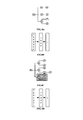
Fig. 8A is a view illustrating a clock channel after configuration of the clock inFig. 7 ; -
Fig. 8B is a view schematically illustrating the remaining nodes not configured in the configuring process inFig. 7 ; -
Fig. 8C is a view illustrating a substitute clock channel after abnormality of the clock channel betweennode 0 andnode 1 in the computer system shown inFig. 6 ; -
Fig. 8D is a view schematically illustrating the remaining nodes not configured in the forming process inFig. 8C ; and -
Fig. 9 is a view schematically illustrating another clock connection of the eight nodes in the computer system shown inFig. 6 . - To make clearer the objectives, technical solutions and advantages of the present invention, the present invention is described in greater detail below with reference to the accompanying drawings.
- The computer system provided by the embodiments of the present invention includes at least two nodes, wherein, as shown in
Fig. 1 , the at least two nodes each include a selectingmodule 11 and a CPU 12,inputs Input 1,... Input N to the selectingmodule 11 are clock src of the current node and clock output from the other node, and an output terminal (output) thereof is connected to the CPU 12 and an input terminal of the selecting module of the other node. - The computer system further includes a
clock controlling module 13, whose output terminal is connected to the control terminal of the selecting module to control the clocks output from the output terminals of the at least two nodes to be the same clock. - In the above technical solution, the input terminal of the selecting module of each node not only has the clock source of the current node but also has clock output of the other node; the selecting module is controlled by a third party such as the aforementioned clock controlling module to select a clock input as the clock input of the node, and it is possible to provide clock for the other node, so as to guarantee that all the nodes use the same clock source; when clocks of plural nodes are abnormal, the computer system can still normally operate as long as there is a normal clock in the computer system.
- When there are two nodes in the computer system, the two nodes are directly connected to each other. As shown in
Fig. 2 , the output terminal of selectingmodule 211 innode 21 is directly connected to the input terminal of selectingmodule 221 innode 22, and the output terminal ofselecting module 221 innode 22 is connected to the input terminal ofselecting module 211 innode 21. Moreover, innode 21 andnode 22, the other inputs to the selecting modules are clocks src of their own nodes. The output terminal of selectingmodule 211 innode 21 is connected toCPU 212 of the current node, and the output terminal ofselecting module 221 innode 22 is connected toCPU 222 of the current node.Nodes - The control terminals of selecting
module 211 and selectingmodule 221 are both controlled by clock controlling module 23 for output. In other words, inputs to the selecting module of each node are the clock of the current node and the clock of the other node. Under control of the clock controlling module 23, the clock src of one node is taken as a common clock source, thereby guaranteeing synchronization of clocks of every node. - In a case where there are four nodes in the computer system, the connection mode among them is similar to that shown in
Fig. 2 , that is, the four nodes are connected to one another via respective selecting modules into a loop, and inputs to the selecting module of each node are clock of the current node and outputs from the selecting modules of the two nodes connected thereto. As shown inFigs. 3A and 3B , the computer system has four nodes, namelynode 31, node 32,node 33 andnode 34, and the selecting modules of the four nodes are sequentially connected into a loop, as shown inFig. 3B . Specifically, innode 31, the output terminal of selecting module 311 is connected to the input terminals of selecting module 321 in node 32 and selecting module 341 innode 34, and connected to CPU 312 of the current node; in node 32, the output terminal of selecting module 321 is connected to the input terminals of selecting module 311 innode 31 and selecting module 331 innode 33, and connected toCPU 332 of the current node; innode 33, the output terminal of selecting module 331 is connected to the input terminals of selecting module 321 in node 32 and selecting module 341 innode 34, and connected toCPU 322 of the current node; and innode 34, the output terminal of selecting module 341 is connected to the input terminals of selecting module 311 innode 31 and selecting module 331 innode 33, and connected toCPU 342 of the current node. Moreover, the control terminals of all the selecting modules are connected to theclock controlling module 35, under control of which all nodes select a clock source src of the one identical node as a common clock source. Likewise, inFig. 3A , the connection between any two nodes is bidirectional connection - that is to say, there are two connection channels, namely clock channels, between two connected nodes; the uninitiated connection channel should be closed. When the clock channel in use becomes abnormal, a clock channel is reselected according to the normal status of the clock channels. - In a case where there are eight nodes in the computer system, the eight nodes are located at various vertices of a cuboid, four nodes within various surfaces of the cuboid are cross connected to one another via selecting modules or any two adjacent nodes are connected to one another via selecting modules, and eventually each node is connected to other three nodes via selecting modules. As shown in
Fig. 4A , the four nodes at various surfaces of the cuboid are sequentially connected via selecting modules into a loop, and connection of the loop is similar to that shown inFig. 3A . Each node is connected to three nodes via selecting modules, and the connection between any two nodes is bidirectional connection - that is to say, there are two connection channels, namely clock channels, between two connected nodes. One connection channel thereof may be closed, and the other connection channel is used. The closed connection channel is initiated when the connection channel in use becomes abnormal. The connection mode of the cuboid as obtained differs from that shown inFig. 3A in the fact that each node is connected to three nodes, specifically, inputs to the selecting module of each node are the clock of the current node and the outputs from the selecting modules of the three nodes connected thereto. - In a case where there are n×8 nodes in the computer system, every eight nodes are located at various vertices of a cuboid, four nodes within each surface of the cuboid are cross connected to one another via selecting modules or connected sequentially one after the other via selecting modules, and each node is connected to 3+n nodes via selecting modules. Connection of the cuboid is similar to that shown in
Fig. 4A . Nodes at the same positions on the cuboids are connected via selecting modules, and inputs to the selecting module of each node are clock of the current node and outputs from the selecting modules of the 3+n nodes connected thereto, wherein n is a natural number. Likewise, the connection between any two nodes is bidirectional connection - that is to say, there are two connection channels, namely clock channels, between two connected nodes. One connection channel thereof may be closed during use, and the other connection channel is used. The closed connection channel is initiated when the connection in use becomes abnormal. - For instance, when there are sixteen nodes in the computer system, a structure as shown in
Fig. 4B is obtained after connection, and when there are thirty-two nodes in the computer system, a structure as shown inFig. 5 is obtained after connection. Node connections for computer systems with sixty-four nodes and one hundred and twenty-eight nodes are similar to those described above. Eight nodes are located at various vertices of a cuboid, and each node is connected to three adjacent nodes. When the system has multiple(s) of eight nodes, every eight nodes connected by the mode mentioned above as a whole can also be regarded as one point, and then each point is connected to the other by the connection mode mentioned above. For instance, sixteen nodes are located at various vertices of two cuboids, and points at the same positions on the two cuboids are then connected. And so on, connections of thirty-two nodes and sixty-four nodes could be realized, which will not be enumerated in this context. - While partitioning the computer system provided by the aforementioned embodiments, in order to guarantee a top fault-tolerant performance of the partition system, nodes with the most connections should be selected to form a partition as far as possible, for instance, two directly connected nodes are constructed as a partition system, or four nodes connected into a loop are constructed as a partition system. For a computer system with n×8 nodes, it is also possible to construct 8 nodes connected into a cuboid as a partition system. This is because clock synchronization merely puts demand on the same partition system, while formation of the nodes with the most connections into a partition system can guarantee, to the maximum degree, that a substitute channel could be found in the case certain nodes in the partition system become abnormal, without affecting other partition systems.
- Moreover, when clocks at nodes are abnormal, it should be guaranteed that at least one node clock in the partition is normal while constructing a partition system, otherwise the partition system would have to use clocks of other partition systems. After partitions are constructed in the computer system, nodes pertaining to the same partition system in the computer system are directly or indirectly connected to one another, and the intermediate nodes of an indirect connection and the two end nodes of the indirect connection are located in the same partition system. In a computer system with nx8 nodes, for example, eight nodes connected into a cuboid are constructed as a partition system.
- After partitioning of the computer system provided by the aforementioned embodiments, if the clock source is abnormal in a certain partition system, operation of the partition system will not be affected as long as there is a normal clock in that partition system. If a certain clock channel of the partition system becomes abnormal, nodes downstream of the abnormal clock channel can properly operate, the partition system can still normally operate as long as there is another normal channel. If a certain node of the partition system functions abnormally, after the abnormal node is removed, the partition system can still normally operate as long as the clocks of the remaining nodes can be interconnected by routing. Thus, if there are so many abnormal nodes in a partition system that the clock channels of the remaining nodes cannot be interconnected by routing, it is impossible to construct a partition with the remaining nodes, but it is possible to newly construct several independent partitions according to the status of the partition.
- Detailed explanation is made below with a minicomputer having eight nodes as an example.
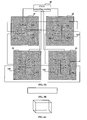
- As shown in
Fig. 6 ,node 0,node 1,..., andnode 7 are connected via selecting modules, and expressed as a cuboid; in other words,node 0 tonode 7 are located at various vertices of the cuboid, four nodes are sequentially connected to form a loop at front, back and lower surfaces of the cuboid, and four nodes at the upper surface of the cuboid are cross connected to one another as backup clock synchronization route - for instance, sequential connection at the front and back surfaces, and cross connection at the upper surface -, this is so because when there are plural nodes going wrong, the probability is relatively high for the directly connected nodes to appear simultaneously, so that the cross connection is adopted in the connections of clocks, while the number of connections of each node remains generally invariant.Fig. 6 visually explains how to find the corresponding clock channel when a certain node clock becomes abnormal, so as to ensure normality of the clock chain. - A clock relation routing table shown in the following Table 1 is generated according to the connection relations illustrated in
Fig. 6 .Table 1: Clock Relation Connection Table Starting Point Finishing Point 0 1, 2, 6 1 0, 3, 7 2 0, 3, 5 3 1, 2, 4 4 3, 5, 6 5 2, 4, 7 6 0, 4, 7 7 1, 5, 6 - When any limited number of clocks and clock channels become abnormal, it is always possible to attempt to find other substitute clock channels from the clock relation routing table, and to use the found substitute clock channels to substitute the abnormal clock channels. Moreover, when selecting a clock, it is needed not only to select whether to use the clock of the node, but also to select the initiated clock channel, thereby ensuring one clock source for all nodes.
- Since it is not possible to have a clock connection between any two nodes, some clock channels need routes of other nodes to form channels; in order to reduce error rate and to enhance setting speed, when partitioning is performed, partitions are constructed in accordance with the aforementioned partitioning mode.
- Suppose a 2P partition system is to be constructed, two directly connected nodes are selected to form a partition system. Generally, various node clocks in a partition system are all provided by the nodes within the partition, so as to prevent partition systems from interfering with each other. If all node clocks of a certain partition system become abnormal, it is possible to provide all nodes of the partition system with clocks by a node of a connected partition system, but whether clocks of the partition system normally operate or not is then controlled by the other partition. Under such a circumstance, it is possible to separate the two nodes from each other to perform partitioning again, and to form two independent 2P partitions with other connected nodes respectively.
- Suppose a 4P partition system is to be constructed. Normally, the fault-tolerant probability is highest when four nodes connected up and down or front and back with one another into a loop are randomly selected to form a partition system. However, if plural node clocks are already abnormal during construction of the partition, the partition should be reasonably constructed according to the aforementioned partitioning principle to ensure that all partition systems can normally operate.
- Suppose a 6P partition system is to be constructed, four nodes are first selected according to the mode in which 4P partition is constructed, and then any two adjacent nodes capable of forming 2P, namely two directly connected nodes, are randomly selected to construct a 6P partition system together with the constructed 4P partition system.
- Suppose an 8P partition system is to be constructed, all nodes in the computer system can form an 8P partition system.
- Clock configuration of a partition system is explained below with an example of an 8P partition system.
- As shown in
Fig. 7 , the configuring flow includes the following steps. - Step 701 - constructing a clock relation connection table according to clock connection modes, as shown in Table 1, each row of Table 1 represents one tier, and each tier has a starting point and a finishing point. The connections between the starting point and the finishing point are bidirectional connection channels, specifically, there is not only a connection channel from the starting point to the finishing point, but also a connection channel from the finishing point to the starting point - for instance, in Table 1,
node 0 is the starting point andnode 1 is the finishing point in the second row, whereasnode 1 is the starting point andnode 0 is the finishing point in the third row. The subsequent steps are performed on repetitive direct or indirect connections for nodes such that the connections are simplified as unidirectional and non-repetitive connections, and directed to selecting from the bidirectional connection channels between directly connected nodes one connection channel as a clock channel between the directly connected nodes and another connection channel as backup, such that clock configuration could be performed again for the partition system in case of clock abnormality, channel abnormality or node abnormality. - Step 702 - detecting normality of each node clock.
- Step 703 - selecting and initiating a clock source. Specifically, a normal node clock is selected as the clock source, among main node clock, node clock of the current partition, and node clock of other partitions in an order of main node clock → node clock of the current partition → node clock of other partitions, and this node clock is initiated.
- Typically, clock of the main node is selected as the clock source, that is to say, if there is no abnormality occurred to it, the clock of the main node is selected; if there is abnormality, the clock of a node directly connected to the main node in the same partition is selected as the clock source. Suppose an 8P partition is constructed in
Fig. 6 ,node 0 is the main node, and abnormality of the clock atnode 0 is detected. In such a case, a normal clock of a node which is connected tonode 0, for example, any one ofnode 1,node 2 andnode 6 connected tonode 0, is selected as the clock source. - Step 704 - adding the node of which the clock is selected as clock source to the clock relation routing table, and setting the node as a starting point of the current tier. The clock relation routing table is similar to Table 1 as they both include starting point and finishing point as table entries, and the difference between them is that in the clock relation routing table, the columns of both the starting point and the finishing point are empty at the very beginning, and corresponding entries are gradually added with the execution of subsequent steps. Taking the computer system shown in
Fig. 6 as an example, if the clock ofnode 0 is the clock source,node 0 is added to the clock relation routing table as the starting point of the first tier. - Step 705 - determining whether all nodes in the partition system have already been added to the clock relation routing table. If all nodes have been added to the clock relation routing table, the clock configuration is completed, otherwise Step 706 is executed.
- Step 706 - determining whether all nodes directly connected to the starting point of the current tier in the partition system have already been added to the clock relation routing table. If they are present in the clock relation routing table, Step 709 is executed, otherwise Step 707 is executed.
- Step 707 - selecting a node directly connected to the starting point of the current tier among nodes directly connected to the starting point of the current tier with normal clock channels and yet to be added to the clock relation routing table.
- Step 708 - adding the node selected in
Step 707 to the clock relation routing table as one entry of the finishing point of the current tier, initiating the clock channel in the direction from the node of the current tier to the node selected inStep 707, and adding the selected node to the next row of the clock relation routing table as one entry of the starting point of the next tier. Thereafter,Step 706 is executed again. - Step 709 - determining whether there are nodes of the same level as the starting point of the current tier, for example, the starting point of the current is N hops away from the clock source, and certain nodes are also N hops away from the clock source. When such kind of node exists and has not been added to the clock relation routing table, and the clock channel between this node serving as the finishing point of the previous tier and the starting point of the previous tier is normal,
Step 712 is executed, otherwise Step 710 is executed. - Step 710 - determining whether there is a starting point of the next tier. If the determination is positive,
Step 711 is executed, otherwise the clock configuration ends. - Step 711 - setting the first found starting point of the next tier as the starting point of the current tier, and continuing to execute
Step 705. - Step 712 - selecting this node as the starting point of the current tier, and continuing to execute
Step 705. - Take the computer system shown in
Fig. 6 as an example, and suppose that in thecomputer system node 0 is the main node, and the clock ofnode 0 is normal. - Then, the clock of
node 0 is selected as the clock source, andnode 0 is added to the clock relation routing table, as shown in Table 2.Table 2: Clock Relation Routing Table Starting Point Finishing Point Node 0 - The remaining nodes which have not been configured in the system are shown in the first upright box in
Fig. 8B . - It is then determined whether the respective connection channels between
node 0 andnodes node 0, are normal; if the respective connection channels betweennode 0 andnodes node 0 tonode 1 is initiated or selected as the clock channel betweennode 0 andnode 1, the connection channel in a direction fromnode 0 tonode 2 is initiated or selected as the clock channel betweennode 0 andnode 2, and the connection channel in a direction fromnode 0 tonode 6 is initiated or selected as the clock channel betweennode 0 andnode 6, andnode 1,node 2 andnode 6 are added to the clock relation routing table as finishing points of the first tier.Table 3 Starting Point Finishing Point Node 0 Node 1,Node 2,Node 6 - Remaining nodes which have not been configured in the system are shown in the second upright box in
Fig. 8B . - Moreover,
node 1,node 2 andnode 6 are taken as the starting points of the next tier to determine whether the connection channels betweennode 1 andnodes node 3 andnode 7 are nodes that are directly connected tonode 1. If the connection channels betweennode 1 andnodes node 1 tonodes 3 is initiated or selected as the clock channel betweennode 1 andnode 3, and the connection channel in a direction fromnode 1 tonodes 7 is initiated or selected as the clock channel betweennode 1 andnode 7, andnode 1,node 3 andnode 7 are added to the clock relation routing table as one tier, withnode 1 being the starting point of the tier andnode 3 andnode 7 being the finishing points of the tier, as shown in Table 4.Table 4 Starting Point Finishing Point Node 0 Node 1,Node 2,Node 6Node 1Node 3,Node 7 - It is determined whether the connection channels between the
node 2 andnode 5, which is directly connected tonode 2, are normal; if the connection channels betweennode 2 andnode 5 are normal, the connection channel in a direction fromnode 2 tonode 5 is taken as the clock channel betweennode 2 andnode 5, andnode 2 andnode 5 are added to the clock relation routing table as one tier, withnode 2 being the starting point of the tier andnode 5 being the finishing point of the tier, as shown in Table 5.Table 5 Starting Point Finishing Point Node 0 Node 1,Node 2,Node 6Node 1Node 3,Node 7Node 2Node 5 - It is determined whether the connection channels between
node 6 andnode 4, which is directly connected tonode 6, are normal; if the connection channels betweennode 6 andnode 4 are normal, the connection channel in a direction fromnode 6 tonode 4 is taken as the clock channel betweennode 6 andnode 4, andnode 6 andnode 4 are added to the clock relation routing table as one tier, withnode 6 being the starting point of the tier andnode 4 being the finishing point of the tier, as shown in Table 6.Table 6 Starting Point Finishing Point Node 0 Node 1,Node 2,Node 6Node 1Node 3,Node 7Node 2Node 5Node 6Node 4 - The corresponding clock routings are shown in
Fig. 8A . - If the clock channel between the configured
node 0 andnode 1 becomes abnormal,nodes node 3 andnode 2, andnode 1 is directly connected tonode 3, so that it is possible to initiate or select the connection channel fromnode 2 tonode 3 as the clock channel betweennode 2 andnode 3, close the connection channel fromnode 1 tonode 3, and initiate the connection channel fromnode 3 tonode 1 as the clock channel betweennode 3 andnode 1, as shown inFig. 8C , so thatnode 1 andnode 3 can still obtain clocks supplied by the clock source. Remaining nodes not configured in the configuring process are as shown inFig. 8D . Moreover, as can be further learnt from the clock connection Table 1, there is backup connection channel betweennode 7 andnode 6, and the connection channel fromnode 6 tonode 7 is initiated as the clock channel betweennode 6 andnode 7, as shown inFig. 8C , thus,node 7 can still obtain the clocks supplied by the clock source. -
Fig. 9 is a view schematically illustrating another clock connection of the eight nodes in the computer system shown inFig. 6 . It is also expressed as a cuboid, with up and down, front and back, and left to right sequential loops, while no crossing is present. The clock relation connection table thereof is shown in Table 7.Table 7 Starting Point Finishing Point 0 1, 3, 4 1 0, 2, 5 2 1, 3, 6 3 0, 2, 7 4 0, 5, 7 5 1, 4, 6 6 2, 5, 7 7 3, 4, 6 - The aforementioned device and method embodiments guarantee clock synchronization of various nodes in a partition system through clock connection channels amongst nodes and the clock configuring method. Moreover, when some of the node clocks are abnormal, the system will not be affected - that is to say, when the system is still not boosted, if some of the node clocks are abnormal, it is still possible to construct a partition to normally run the system. When some of the node clock channels are abnormal, it is maximally guaranteed that the partition system is not affected. When some of the nodes are abnormal, it is maximally guaranteed that a partition system formed by the remaining nodes is not affected. When the number of abnormal nodes is too many to construct a partition, it is still possible to use the remaining nodes to construct several independent partition systems.
- The clock connection modes among the nodes in the aforementioned device and method embodiments can also be applied to quick path interconnect (QPI) of partitions, and can be applied to similar connections among nodes in other systems.
- It is apparent to those ordinarily skilled in the art that the entire or partial steps in the aforementioned method embodiments can be realized by a program that instructs relevant hardware, and the program can be stored in a computer-readable storage medium and, when executed, executes the steps of the aforementioned method embodiments; the storage medium may include such program-code-storing medium as a read-only memory (ROM), a random access memory (RAM), a magnetic disk or an optical disk.
- Finally, it should be noted that the above embodiments are merely used to describe the technical solutions of the present invention, rather than to restrict the present invention. Although the present invention is described in detail with reference to the foregoing embodiments, it should be understood by those ordinarily skilled in the art that it is still possible to modify the technical solutions recorded in the various foregoing embodiments or to equivalently substitute partial technical features thereof. These modifications or substitutions will not make the essence of the corresponding technical solutions depart from the scope of the technical solutions of the present claims.
Claims (6)
- A computer system, comprising:at least two nodes, wherein each of the at least two nodes (21, 22) includes a selecting module (211, 221) and a CPU (212, 222), wherein inputs to the selecting modules (211, 221) comprise clock of local node and clock output from other node, and an output terminal of the selecting modules (211, 221) is connected to the CPU (212, 222) and an input terminal of the selecting module (211, 221) of other node;the computer system further comprising a clock controlling module (213), wherein an output terminal of the clock controlling module (213) is connected to a control terminal of the selecting module (211, 221) of each of the at least two nodes (21, 22), for controlling the clocks of the at least two nodes to be the same clock,wherein the clock controlling module (213) controls the selecting modules of the at least two nodes to select a clock of one of the at least two nodes as a common clock source for the at least two nodes, and when the clock of the selected node becomes abnormal, the clock controlling module (213) controls the selecting modules (211, 221) of the rest of the at least two nodes to select another available common clock source according to clock channels recorded in a clock relation connection table such that the rest of the at least two nodes are provided with the same clock, the clock channel being a route from one of the at least two nodes to any of the rest of the at least two nodes.
- The computer system according to claim 1, wherein the at least two nodes are four nodes connected to one another via selecting modules (211, 221) into a loop, wherein inputs to the selecting module (211, 221) of each node comprise clock of the node and outputs from the selecting modules (211, 221) of two nodes connected thereto.
- The computer system according to claim 1, wherein the at least two nodes are eight nodes respectively located at each vertex of a cuboid, wherein the four nodes within various surfaces of the cuboid are cross connected to one another via selecting modules (211, 221) or every two adjacent nodes are connected to one another via selecting modules (211, 221), each node is connected to three nodes via selecting modules (211, 221), and inputs to the selecting module (211, 221) of each node comprise clock of the node and outputs from the selecting modules (211, 221) of the three nodes connected thereto.
- The computer system according to claim 1, wherein the at least two nodes are n×8 nodes, wherein every eight nodes are respectively located at each vertex of a cuboid, four nodes within each surface of the cuboid are cross connected to one another via selecting modules (211, 221) or sequentially connected one after the other via selecting modules (211, 221), each node is connected to 3+n nodes via selecting modules (211, 221), nodes at the same positions on each cuboid are connected via selecting modules (211, 221), and inputs to the selecting module (211, 221) of each node comprise clock of the node and outputs from the selecting modules (211, 221) of the 3+n nodes connected thereto, wherein n is a natural number that is greater than 0.
- The computer system according to any one of claims 2 to 4, wherein nodes that are directly or indirectly connected to one another form a partition system in the computer system, and intermediate nodes on a clock channel and nodes at both ends of the clock channel are located in the identical partition system.
- The computer system according to any one of claims 1 to 4, wherein connection between the output terminal of the selecting module (211, 221) and the input terminal of the selecting module (211, 221) of other node is achieved via a CPU interconnection cable.
Applications Claiming Priority (1)
| Application Number | Priority Date | Filing Date | Title |
|---|---|---|---|
| PCT/CN2011/077625 WO2012106929A1 (en) | 2011-07-26 | 2011-07-26 | Computer system and clock configuration method thereof |
Publications (3)
| Publication Number | Publication Date |
|---|---|
| EP2573643A1 EP2573643A1 (en) | 2013-03-27 |
| EP2573643A4 EP2573643A4 (en) | 2014-08-27 |
| EP2573643B1 true EP2573643B1 (en) | 2015-09-23 |
Family
ID=45429409
Family Applications (1)
| Application Number | Title | Priority Date | Filing Date |
|---|---|---|---|
| EP11858207.1A Active EP2573643B1 (en) | 2011-07-26 | 2011-07-26 | Computer system and clock configuration method thereof |
Country Status (4)
| Country | Link |
|---|---|
| US (1) | US9026835B2 (en) |
| EP (1) | EP2573643B1 (en) |
| CN (1) | CN102317885B (en) |
| WO (1) | WO2012106929A1 (en) |
Families Citing this family (2)
| Publication number | Priority date | Publication date | Assignee | Title |
|---|---|---|---|---|
| CN102317885B (en) * | 2011-07-26 | 2014-05-07 | 华为技术有限公司 | Computer system and method of configuring clock thereof |
| CN105022715A (en) * | 2015-07-08 | 2015-11-04 | 浪潮(北京)电子信息产业有限公司 | Server backplane interconnection method and system |
Family Cites Families (24)
| Publication number | Priority date | Publication date | Assignee | Title |
|---|---|---|---|---|
| US4239982A (en) * | 1978-06-14 | 1980-12-16 | The Charles Stark Draper Laboratory, Inc. | Fault-tolerant clock system |
| GB2227341A (en) * | 1989-01-18 | 1990-07-25 | Intel Corp | Message routing in a multiprocessor computer system |
| US5249206A (en) * | 1989-08-11 | 1993-09-28 | International Business Machines Corporation | Fault-tolerant clock for multicomputer complex |
| US5404363A (en) * | 1991-11-27 | 1995-04-04 | Honeywell Inc. | Two-fail-operational fault-tolerant multiple clock system |
| JPH0778039A (en) * | 1993-09-08 | 1995-03-20 | Fujitsu Ltd | Clock selection control system |
| US5758132A (en) * | 1995-03-29 | 1998-05-26 | Telefonaktiebolaget Lm Ericsson | Clock control system and method using circuitry operating at lower clock frequency for selecting and synchronizing the switching of higher frequency clock signals |
| SE504920C2 (en) * | 1995-09-29 | 1997-05-26 | Ericsson Telefon Ab L M | Method and system for redundant clock distribution to telecommunications equipment in which switching of selected clock signal among the incoming clock signals is constantly taking place |
| JPH11103312A (en) * | 1997-09-26 | 1999-04-13 | Mitsubishi Electric Corp | Clock synchronization management system for network |
| US6754171B1 (en) * | 2000-05-18 | 2004-06-22 | Enterasys Networks, Inc. | Method and system for distributed clock failure protection in a packet switched network |
| US6592449B2 (en) | 2001-02-24 | 2003-07-15 | International Business Machines Corporation | Smart fan modules and system |
| CA2437661A1 (en) * | 2001-02-24 | 2002-09-06 | International Business Machines Corporation | A global tree network for computing structures |
| CN1281005C (en) * | 2001-06-29 | 2006-10-18 | 中兴通讯股份有限公司 | Method and device for choosing and controlling clock source of synchronous digital optical network |
| US7089442B2 (en) * | 2003-02-07 | 2006-08-08 | Rambus Inc. | Fault-tolerant clock generator |
| US7230468B2 (en) * | 2004-03-10 | 2007-06-12 | Hewlett-Packard Development Company, L.P. | Systems and methods for providing distributed control signal redundancy among electronic circuits |
| US7602869B2 (en) | 2005-07-29 | 2009-10-13 | International Business Machines Corporation | Methods and apparatus for clock synchronization and data recovery in a receiver |
| US7562247B2 (en) * | 2006-05-16 | 2009-07-14 | International Business Machines Corporation | Providing independent clock failover for scalable blade servers |
| US7870413B2 (en) * | 2006-08-15 | 2011-01-11 | Mitac International Corp. | Synchronization clocking scheme for small scalable multi-processor system |
| CN101192913B (en) * | 2007-08-08 | 2010-12-08 | 中兴通讯股份有限公司 | A system and method for clock synchronization and clock switch over optical transmission network |
| CN100525212C (en) * | 2007-08-10 | 2009-08-05 | 中控科技集团有限公司 | Method and system for network clock synchronous |
| US8161311B2 (en) * | 2007-08-23 | 2012-04-17 | Stratus Technologies Bermuda Ltd | Apparatus and method for redundant and spread spectrum clocking |
| US8239704B2 (en) * | 2009-06-12 | 2012-08-07 | Cray Inc. | Global clock via embedded spanning tree |
| JP5841532B2 (en) * | 2009-07-31 | 2016-01-13 | ヒューレット−パッカード デベロップメント カンパニー エル.ピー.Hewlett‐Packard Development Company, L.P. | Providing fault-tolerant spread spectrum clock signals in the system |
| US8212601B2 (en) * | 2010-10-29 | 2012-07-03 | Netgear, Inc. | Method and apparatus for providing system clock failover |
| CN102317885B (en) * | 2011-07-26 | 2014-05-07 | 华为技术有限公司 | Computer system and method of configuring clock thereof |
-
2011
- 2011-07-26 CN CN201180001193.7A patent/CN102317885B/en active Active
- 2011-07-26 WO PCT/CN2011/077625 patent/WO2012106929A1/en active Application Filing
- 2011-07-26 EP EP11858207.1A patent/EP2573643B1/en active Active
-
2012
- 2012-12-17 US US13/717,205 patent/US9026835B2/en active Active
Also Published As
| Publication number | Publication date |
|---|---|
| US20130103971A1 (en) | 2013-04-25 |
| CN102317885B (en) | 2014-05-07 |
| EP2573643A1 (en) | 2013-03-27 |
| CN102317885A (en) | 2012-01-11 |
| EP2573643A4 (en) | 2014-08-27 |
| US9026835B2 (en) | 2015-05-05 |
| WO2012106929A1 (en) | 2012-08-16 |
Similar Documents
| Publication | Publication Date | Title |
|---|---|---|
| US7032013B2 (en) | Reliability for interconnect fabrics | |
| US9726716B2 (en) | Configurable vertical integration | |
| JP2011216020A (en) | Information processing apparatus and circuit reconfiguration device | |
| JP6004079B2 (en) | Switches and programs | |
| EP2573643B1 (en) | Computer system and clock configuration method thereof | |
| CN110941666A (en) | Database multi-activity method and device | |
| US11531637B2 (en) | Embedding rings on a toroid computer network | |
| JP2009151629A (en) | Node system, server switching method, server device, data transfer method, and program | |
| JP2004110803A (en) | Fault tolerant computer, its transaction synchronous control method and program | |
| JP2003009194A (en) | Optical crossconnect system and its controller and controlling method | |
| CN114546978B (en) | Bitmap management method, system, equipment and medium for storage cluster | |
| JP6889138B2 (en) | Storage device and storage method | |
| US10516625B2 (en) | Network entities on ring networks | |
| JP7358819B2 (en) | IO module duplication control device and method | |
| US9118546B2 (en) | Data forwarding method and router | |
| JP2602421B2 (en) | Clock reception distribution system | |
| JP7120599B2 (en) | Information processing system and control method | |
| WO2015184763A1 (en) | Method, apparatus and system for instructing to select synchronization time source | |
| US6591030B2 (en) | Method of mirror layout of multi-level optical switch | |
| JPH01208047A (en) | Clock supplying system | |
| CN110673793A (en) | Storage device node event management method and system, electronic device and storage medium | |
| Tzeng | Reliable butterfly distributed-memory multiprocessors | |
| JP5611088B2 (en) | System bus diagnostic device | |
| CN117354222A (en) | SR micro-ring prevention method, device, computer equipment and storage medium | |
| CN112231142A (en) | System backup recovery method and device, computer equipment and storage medium |
Legal Events
| Date | Code | Title | Description |
|---|---|---|---|
| PUAI | Public reference made under article 153(3) epc to a published international application that has entered the european phase |
Free format text: ORIGINAL CODE: 0009012 |
|
| 17P | Request for examination filed |
Effective date: 20121219 |
|
| AK | Designated contracting states |
Kind code of ref document: A1 Designated state(s): AL AT BE BG CH CY CZ DE DK EE ES FI FR GB GR HR HU IE IS IT LI LT LU LV MC MK MT NL NO PL PT RO RS SE SI SK SM TR |
|
| A4 | Supplementary search report drawn up and despatched |
Effective date: 20140730 |
|
| RIC1 | Information provided on ipc code assigned before grant |
Ipc: G06F 11/16 20060101ALI20140724BHEP Ipc: G06F 1/12 20060101AFI20140724BHEP Ipc: G06F 11/20 20060101ALN20140724BHEP |
|
| DAX | Request for extension of the european patent (deleted) | ||
| GRAP | Despatch of communication of intention to grant a patent |
Free format text: ORIGINAL CODE: EPIDOSNIGR1 |
|
| RIC1 | Information provided on ipc code assigned before grant |
Ipc: G06F 1/12 20060101AFI20150323BHEP Ipc: G06F 11/20 20060101ALN20150323BHEP Ipc: G06F 11/16 20060101ALI20150323BHEP |
|
| RIC1 | Information provided on ipc code assigned before grant |
Ipc: G06F 1/12 20060101AFI20150330BHEP Ipc: G06F 11/20 20060101ALN20150330BHEP Ipc: G06F 11/16 20060101ALI20150330BHEP |
|
| INTG | Intention to grant announced |
Effective date: 20150415 |
|
| GRAS | Grant fee paid |
Free format text: ORIGINAL CODE: EPIDOSNIGR3 |
|
| GRAA | (expected) grant |
Free format text: ORIGINAL CODE: 0009210 |
|
| AK | Designated contracting states |
Kind code of ref document: B1 Designated state(s): AL AT BE BG CH CY CZ DE DK EE ES FI FR GB GR HR HU IE IS IT LI LT LU LV MC MK MT NL NO PL PT RO RS SE SI SK SM TR |
|
| REG | Reference to a national code |
Ref country code: GB Ref legal event code: FG4D |
|
| REG | Reference to a national code |
Ref country code: CH Ref legal event code: EP |
|
| REG | Reference to a national code |
Ref country code: AT Ref legal event code: REF Ref document number: 751572 Country of ref document: AT Kind code of ref document: T Effective date: 20151015 |
|
| REG | Reference to a national code |
Ref country code: IE Ref legal event code: FG4D |
|
| REG | Reference to a national code |
Ref country code: DE Ref legal event code: R096 Ref document number: 602011020094 Country of ref document: DE |
|
| REG | Reference to a national code |
Ref country code: SE Ref legal event code: TRGR |
|
| REG | Reference to a national code |
Ref country code: NL Ref legal event code: MP Effective date: 20150923 |
|
| PG25 | Lapsed in a contracting state [announced via postgrant information from national office to epo] |
Ref country code: GR Free format text: LAPSE BECAUSE OF FAILURE TO SUBMIT A TRANSLATION OF THE DESCRIPTION OR TO PAY THE FEE WITHIN THE PRESCRIBED TIME-LIMIT Effective date: 20151224 Ref country code: FI Free format text: LAPSE BECAUSE OF FAILURE TO SUBMIT A TRANSLATION OF THE DESCRIPTION OR TO PAY THE FEE WITHIN THE PRESCRIBED TIME-LIMIT Effective date: 20150923 Ref country code: NO Free format text: LAPSE BECAUSE OF FAILURE TO SUBMIT A TRANSLATION OF THE DESCRIPTION OR TO PAY THE FEE WITHIN THE PRESCRIBED TIME-LIMIT Effective date: 20151223 Ref country code: LV Free format text: LAPSE BECAUSE OF FAILURE TO SUBMIT A TRANSLATION OF THE DESCRIPTION OR TO PAY THE FEE WITHIN THE PRESCRIBED TIME-LIMIT Effective date: 20150923 Ref country code: LT Free format text: LAPSE BECAUSE OF FAILURE TO SUBMIT A TRANSLATION OF THE DESCRIPTION OR TO PAY THE FEE WITHIN THE PRESCRIBED TIME-LIMIT Effective date: 20150923 |
|
| REG | Reference to a national code |
Ref country code: LT Ref legal event code: MG4D |
|
| REG | Reference to a national code |
Ref country code: AT Ref legal event code: MK05 Ref document number: 751572 Country of ref document: AT Kind code of ref document: T Effective date: 20150923 |
|
| PG25 | Lapsed in a contracting state [announced via postgrant information from national office to epo] |
Ref country code: HR Free format text: LAPSE BECAUSE OF FAILURE TO SUBMIT A TRANSLATION OF THE DESCRIPTION OR TO PAY THE FEE WITHIN THE PRESCRIBED TIME-LIMIT Effective date: 20150923 Ref country code: RS Free format text: LAPSE BECAUSE OF FAILURE TO SUBMIT A TRANSLATION OF THE DESCRIPTION OR TO PAY THE FEE WITHIN THE PRESCRIBED TIME-LIMIT Effective date: 20150923 |
|
| PG25 | Lapsed in a contracting state [announced via postgrant information from national office to epo] |
Ref country code: NL Free format text: LAPSE BECAUSE OF FAILURE TO SUBMIT A TRANSLATION OF THE DESCRIPTION OR TO PAY THE FEE WITHIN THE PRESCRIBED TIME-LIMIT Effective date: 20150923 |
|
| PG25 | Lapsed in a contracting state [announced via postgrant information from national office to epo] |
Ref country code: ES Free format text: LAPSE BECAUSE OF FAILURE TO SUBMIT A TRANSLATION OF THE DESCRIPTION OR TO PAY THE FEE WITHIN THE PRESCRIBED TIME-LIMIT Effective date: 20150923 Ref country code: CZ Free format text: LAPSE BECAUSE OF FAILURE TO SUBMIT A TRANSLATION OF THE DESCRIPTION OR TO PAY THE FEE WITHIN THE PRESCRIBED TIME-LIMIT Effective date: 20150923 Ref country code: EE Free format text: LAPSE BECAUSE OF FAILURE TO SUBMIT A TRANSLATION OF THE DESCRIPTION OR TO PAY THE FEE WITHIN THE PRESCRIBED TIME-LIMIT Effective date: 20150923 Ref country code: IS Free format text: LAPSE BECAUSE OF FAILURE TO SUBMIT A TRANSLATION OF THE DESCRIPTION OR TO PAY THE FEE WITHIN THE PRESCRIBED TIME-LIMIT Effective date: 20160123 Ref country code: SK Free format text: LAPSE BECAUSE OF FAILURE TO SUBMIT A TRANSLATION OF THE DESCRIPTION OR TO PAY THE FEE WITHIN THE PRESCRIBED TIME-LIMIT Effective date: 20150923 Ref country code: IT Free format text: LAPSE BECAUSE OF FAILURE TO SUBMIT A TRANSLATION OF THE DESCRIPTION OR TO PAY THE FEE WITHIN THE PRESCRIBED TIME-LIMIT Effective date: 20150923 |
|
| PG25 | Lapsed in a contracting state [announced via postgrant information from national office to epo] |
Ref country code: PT Free format text: LAPSE BECAUSE OF FAILURE TO SUBMIT A TRANSLATION OF THE DESCRIPTION OR TO PAY THE FEE WITHIN THE PRESCRIBED TIME-LIMIT Effective date: 20160125 Ref country code: AT Free format text: LAPSE BECAUSE OF FAILURE TO SUBMIT A TRANSLATION OF THE DESCRIPTION OR TO PAY THE FEE WITHIN THE PRESCRIBED TIME-LIMIT Effective date: 20150923 Ref country code: PL Free format text: LAPSE BECAUSE OF FAILURE TO SUBMIT A TRANSLATION OF THE DESCRIPTION OR TO PAY THE FEE WITHIN THE PRESCRIBED TIME-LIMIT Effective date: 20150923 Ref country code: RO Free format text: LAPSE BECAUSE OF FAILURE TO SUBMIT A TRANSLATION OF THE DESCRIPTION OR TO PAY THE FEE WITHIN THE PRESCRIBED TIME-LIMIT Effective date: 20150923 |
|
| REG | Reference to a national code |
Ref country code: DE Ref legal event code: R097 Ref document number: 602011020094 Country of ref document: DE |
|
| PLBE | No opposition filed within time limit |
Free format text: ORIGINAL CODE: 0009261 |
|
| STAA | Information on the status of an ep patent application or granted ep patent |
Free format text: STATUS: NO OPPOSITION FILED WITHIN TIME LIMIT |
|
| 26N | No opposition filed |
Effective date: 20160624 |
|
| PG25 | Lapsed in a contracting state [announced via postgrant information from national office to epo] |
Ref country code: DK Free format text: LAPSE BECAUSE OF FAILURE TO SUBMIT A TRANSLATION OF THE DESCRIPTION OR TO PAY THE FEE WITHIN THE PRESCRIBED TIME-LIMIT Effective date: 20150923 |
|
| PG25 | Lapsed in a contracting state [announced via postgrant information from national office to epo] |
Ref country code: SI Free format text: LAPSE BECAUSE OF FAILURE TO SUBMIT A TRANSLATION OF THE DESCRIPTION OR TO PAY THE FEE WITHIN THE PRESCRIBED TIME-LIMIT Effective date: 20150923 |
|
| PG25 | Lapsed in a contracting state [announced via postgrant information from national office to epo] |
Ref country code: BE Free format text: LAPSE BECAUSE OF FAILURE TO SUBMIT A TRANSLATION OF THE DESCRIPTION OR TO PAY THE FEE WITHIN THE PRESCRIBED TIME-LIMIT Effective date: 20150923 |
|
| REG | Reference to a national code |
Ref country code: CH Ref legal event code: PL |
|
| PG25 | Lapsed in a contracting state [announced via postgrant information from national office to epo] |
Ref country code: MC Free format text: LAPSE BECAUSE OF FAILURE TO SUBMIT A TRANSLATION OF THE DESCRIPTION OR TO PAY THE FEE WITHIN THE PRESCRIBED TIME-LIMIT Effective date: 20150923 |
|
| PG25 | Lapsed in a contracting state [announced via postgrant information from national office to epo] |
Ref country code: CH Free format text: LAPSE BECAUSE OF NON-PAYMENT OF DUE FEES Effective date: 20160731 Ref country code: FR Free format text: LAPSE BECAUSE OF NON-PAYMENT OF DUE FEES Effective date: 20160801 Ref country code: LI Free format text: LAPSE BECAUSE OF NON-PAYMENT OF DUE FEES Effective date: 20160731 |
|
| REG | Reference to a national code |
Ref country code: FR Ref legal event code: ST Effective date: 20170331 |
|
| REG | Reference to a national code |
Ref country code: IE Ref legal event code: MM4A |
|
| PG25 | Lapsed in a contracting state [announced via postgrant information from national office to epo] |
Ref country code: IE Free format text: LAPSE BECAUSE OF NON-PAYMENT OF DUE FEES Effective date: 20160726 |
|
| PG25 | Lapsed in a contracting state [announced via postgrant information from national office to epo] |
Ref country code: LU Free format text: LAPSE BECAUSE OF NON-PAYMENT OF DUE FEES Effective date: 20160726 |
|
| PG25 | Lapsed in a contracting state [announced via postgrant information from national office to epo] |
Ref country code: CY Free format text: LAPSE BECAUSE OF FAILURE TO SUBMIT A TRANSLATION OF THE DESCRIPTION OR TO PAY THE FEE WITHIN THE PRESCRIBED TIME-LIMIT Effective date: 20150923 Ref country code: SM Free format text: LAPSE BECAUSE OF FAILURE TO SUBMIT A TRANSLATION OF THE DESCRIPTION OR TO PAY THE FEE WITHIN THE PRESCRIBED TIME-LIMIT Effective date: 20150923 Ref country code: HU Free format text: LAPSE BECAUSE OF FAILURE TO SUBMIT A TRANSLATION OF THE DESCRIPTION OR TO PAY THE FEE WITHIN THE PRESCRIBED TIME-LIMIT; INVALID AB INITIO Effective date: 20110726 |
|
| PG25 | Lapsed in a contracting state [announced via postgrant information from national office to epo] |
Ref country code: MT Free format text: LAPSE BECAUSE OF NON-PAYMENT OF DUE FEES Effective date: 20160731 Ref country code: MK Free format text: LAPSE BECAUSE OF FAILURE TO SUBMIT A TRANSLATION OF THE DESCRIPTION OR TO PAY THE FEE WITHIN THE PRESCRIBED TIME-LIMIT Effective date: 20150923 Ref country code: TR Free format text: LAPSE BECAUSE OF FAILURE TO SUBMIT A TRANSLATION OF THE DESCRIPTION OR TO PAY THE FEE WITHIN THE PRESCRIBED TIME-LIMIT Effective date: 20150923 |
|
| PG25 | Lapsed in a contracting state [announced via postgrant information from national office to epo] |
Ref country code: BG Free format text: LAPSE BECAUSE OF FAILURE TO SUBMIT A TRANSLATION OF THE DESCRIPTION OR TO PAY THE FEE WITHIN THE PRESCRIBED TIME-LIMIT Effective date: 20150923 |
|
| PG25 | Lapsed in a contracting state [announced via postgrant information from national office to epo] |
Ref country code: AL Free format text: LAPSE BECAUSE OF FAILURE TO SUBMIT A TRANSLATION OF THE DESCRIPTION OR TO PAY THE FEE WITHIN THE PRESCRIBED TIME-LIMIT Effective date: 20150923 |
|
| PGFP | Annual fee paid to national office [announced via postgrant information from national office to epo] |
Ref country code: SE Payment date: 20230613 Year of fee payment: 13 |
|
| PGFP | Annual fee paid to national office [announced via postgrant information from national office to epo] |
Ref country code: GB Payment date: 20230601 Year of fee payment: 13 |
|
| PGFP | Annual fee paid to national office [announced via postgrant information from national office to epo] |
Ref country code: DE Payment date: 20230531 Year of fee payment: 13 |