EP2573301A2 - Rear lock for a motor vehicle - Google Patents
Rear lock for a motor vehicle Download PDFInfo
- Publication number
- EP2573301A2 EP2573301A2 EP12180545A EP12180545A EP2573301A2 EP 2573301 A2 EP2573301 A2 EP 2573301A2 EP 12180545 A EP12180545 A EP 12180545A EP 12180545 A EP12180545 A EP 12180545A EP 2573301 A2 EP2573301 A2 EP 2573301A2
- Authority
- EP
- European Patent Office
- Prior art keywords
- pawl
- movement
- rotary latch
- rear lock
- rotary
- Prior art date
- Legal status (The legal status is an assumption and is not a legal conclusion. Google has not performed a legal analysis and makes no representation as to the accuracy of the status listed.)
- Granted
Links
- 230000033001 locomotion Effects 0.000 claims abstract description 204
- 238000013016 damping Methods 0.000 claims description 12
- 230000000694 effects Effects 0.000 claims description 3
- 239000003340 retarding agent Substances 0.000 claims 1
- 230000008878 coupling Effects 0.000 description 39
- 238000010168 coupling process Methods 0.000 description 39
- 238000005859 coupling reaction Methods 0.000 description 39
- 230000005540 biological transmission Effects 0.000 description 31
- 238000000034 method Methods 0.000 description 17
- 230000008569 process Effects 0.000 description 14
- 230000003111 delayed effect Effects 0.000 description 6
- 230000008901 benefit Effects 0.000 description 4
- 230000008859 change Effects 0.000 description 4
- 230000015556 catabolic process Effects 0.000 description 2
- 238000010276 construction Methods 0.000 description 2
- 238000006731 degradation reaction Methods 0.000 description 2
- 230000001934 delay Effects 0.000 description 2
- 230000009467 reduction Effects 0.000 description 2
- 230000000979 retarding effect Effects 0.000 description 2
- 230000001133 acceleration Effects 0.000 description 1
- 230000009471 action Effects 0.000 description 1
- 238000013459 approach Methods 0.000 description 1
- 230000000295 complement effect Effects 0.000 description 1
- 230000006835 compression Effects 0.000 description 1
- 238000007906 compression Methods 0.000 description 1
- 230000001419 dependent effect Effects 0.000 description 1
- 238000013461 design Methods 0.000 description 1
- 238000011161 development Methods 0.000 description 1
- 230000018109 developmental process Effects 0.000 description 1
- 230000002996 emotional effect Effects 0.000 description 1
- 230000002349 favourable effect Effects 0.000 description 1
- 238000007689 inspection Methods 0.000 description 1
- 230000003993 interaction Effects 0.000 description 1
- 238000002955 isolation Methods 0.000 description 1
- 230000007246 mechanism Effects 0.000 description 1
- 238000012986 modification Methods 0.000 description 1
- 230000004048 modification Effects 0.000 description 1
- 230000007935 neutral effect Effects 0.000 description 1
- 230000036316 preload Effects 0.000 description 1
- 238000007789 sealing Methods 0.000 description 1
- 238000012546 transfer Methods 0.000 description 1
Images


Classifications
-
- E—FIXED CONSTRUCTIONS
- E05—LOCKS; KEYS; WINDOW OR DOOR FITTINGS; SAFES
- E05B—LOCKS; ACCESSORIES THEREFOR; HANDCUFFS
- E05B77/00—Vehicle locks characterised by special functions or purposes
- E05B77/42—Means for damping the movement of lock parts, e.g. slowing down the return movement of a handle
-
- E—FIXED CONSTRUCTIONS
- E05—LOCKS; KEYS; WINDOW OR DOOR FITTINGS; SAFES
- E05B—LOCKS; ACCESSORIES THEREFOR; HANDCUFFS
- E05B81/00—Power-actuated vehicle locks
- E05B81/12—Power-actuated vehicle locks characterised by the function or purpose of the powered actuators
- E05B81/14—Power-actuated vehicle locks characterised by the function or purpose of the powered actuators operating on bolt detents, e.g. for unlatching the bolt
-
- E—FIXED CONSTRUCTIONS
- E05—LOCKS; KEYS; WINDOW OR DOOR FITTINGS; SAFES
- E05B—LOCKS; ACCESSORIES THEREFOR; HANDCUFFS
- E05B81/00—Power-actuated vehicle locks
- E05B81/12—Power-actuated vehicle locks characterised by the function or purpose of the powered actuators
- E05B81/20—Power-actuated vehicle locks characterised by the function or purpose of the powered actuators for assisting final closing or for initiating opening
Definitions
- a rear lock of the aforementioned type which can be referred to quite generally as a motor vehicle door lock, is for example from the DE 10 2007 024 672 A1 known and used for example in a tailgate of a motor vehicle.
- a rear lock or such a motor vehicle door lock comprises a lock element, which is connected to a boot lid and is usually equipped with a rotary latch, and a lock counterpart connected to a body of the motor vehicle, which may be in the form of a striker or striker.
- a user actuates (eg by means of an electronic key) a control device, by means of which the tailgate can be opened by means of a drive element, which is preferably operated by an electric motor.
- the invention has for its object to provide a solution that provides a rear lock or a motor vehicle door lock in a structurally simple manner and cost, in which the opening noise is reduced to a minimum, or at least in which the opening process no clearly audible and the comfort negatively impairing Noise generated.
- delay means are provided which are coupled to the rotary latch to delay a speed of movement of the rotary latch to release the closing element.
- the movement of the rotary latch in the rear lock according to the invention can be a rotation or rotational movement. It may also be several delay means or even a single delay means. In the further course of the description, therefore, the input and the plurality of delay means are simultaneously addressed.
- a rear lock but also quite generally a motor vehicle door lock, available which enhances the comfort and quality of the closure and its operation.
- the motor vehicle door lock according to the invention in particular the rear lock, is characterized by a functional design and has a simple and inexpensive construction. Due to the delayed movement of the rotary latch and the trigger mechanism of the motor vehicle door lock and the rear lock according to the present invention, the pawl and the rotary latch during a movement operation of the pawl in the direction of the release position are still in engagement. Although this movement does not allow the opening of the tailgate.
- the bias of the tailgate degrades because the defined and delayed movement of the pawl causes a relative movement between the motor vehicle door lock and the closing element and thus relieving the tailgate, wherein the rotary latch to a predetermined rotational movement is turned in the open position.
- the invention provides that the bias between the tailgate or motor vehicle door lock and closing element is reduced before the pawl and the rotary latch are disengaged.
- the invention also provides a motor vehicle door lock with a locking element in the closed position and in the direction of an open position releasing the open position biased latch, a pawl which engages in an engaged position with the rotary latch in such a manner that the rotary latch on a movement in the direction of the open position is prevented, and a drive element, with which a coupling portion of the pawl is coupled for movement and which the pawl between the engaged position and a Release position moves, in which the pawl with the catch is disengaged, so that the catch can move in the direction of the open position, the task here is inventively achieved in that the drive element, the pawl during movement from the engaged position in the direction of the release position moved so that during this movement with the pawl still engaged rotary catch moves in the direction of the open position.
- the controlled movement of the pawl can be realized in an embodiment of the rear lock according to the invention and also a general motor vehicle door closure that a pivotable about a pivot rotary joint is provided, which is rotatable about a rotation axis pawl mounted on the pivot radially offset from the pivot point.
- a pivotable about a pivot rotary joint is provided, which is rotatable about a rotation axis pawl mounted on the pivot radially offset from the pivot point.
- the invention provides in an embodiment of a push rod, of which a first end is pivotally and radially offset from a rotational axis of a rotary lever or radial approach is coupled thereto and coupled by a second end to the rotary joint in the region of the axis of rotation of the pawl such is that moves the axis of rotation of the pawl along a circular segment-shaped trajectory about the pivot point of the pivot joint during movement of the push rod.
- a first toggle lever is defined by the second end of the push rod and the fixedly mounted pivot, wherein the pawl is coupled via the rotation axis with the pivot and with the push rod.
- a second toggle lever is defined by the first end of the push rod and its eccentric or radially offset with respect to the axis of rotation coupling with the rotary lever, so that a total of a double toggle is present.
- the invention provides that the rotary joint is coupled with a variable-length lever, which is designed to brake the movement of the pawl from the engaged position to an intermediate position and braking from the intermediate position into the release position.
- a variable-length lever which is designed to brake the movement of the pawl from the engaged position to an intermediate position and braking from the intermediate position into the release position.
- This configuration causes the movement of the pawl from the engaged position to the release position and back to the engaged position by a motor-driven Drive element is controlled guided.
- the drive element is used in a first movement section from the engaged position to an intermediate position as a drive for the pawl, whereas the drive element acts as a brake during the movement of the pawl from the intermediate position to the release position.
- the change in the operation of the drive element results from the fact that the intermediate position defines a load change for the drive element.
- the invention provides that the intermediate position is a dead center of the pawl, in which at least the force acting on the pawl force of the catch and the axis of rotation of the pawl are arranged lying in a line.
- the dead center position or intermediate position describes a position of the pawl, which can only be changed by a force transverse to the line, which is formed by the axis of rotation and the force acting on the pawl force of the rotary latch.
- the delay means simultaneously effect an actuation of the pawl.
- the delay means serve not only the delay of the movement of the rotary latch, but also an actuation and possibly movement of the pawl.
- the rotary joint and / or the push rod and / or the drive element may be the delay means, which allows a simple and inexpensive construction of the rear lock and the motor vehicle door lock.
- the invention provides a damping element, in particular a mechanical, hydraulic or pneumatic damping element, serves as a retarding means.
- the damping element may be a linear damping element, wherein the damping element does not serve as an end stop for cushioning the end movement of the rotary latch, but rather dampens, brakes and thereby delays the initial movement of the rotary latch.
- This movement refers to a latching portion of the pawl, which engages in the engaged position with the rotary latch.
- the drive element for opening the motor vehicle door lock is rotated such that the pawl or at least a portion of the pawl, ie the latching portion, initially during movement from the engaged position in the direction of the release position is moved substantially tangentially with respect to the rotary latch and then to disengage the pawl and the catch, is moved substantially radially away from the catch.
- the movement of the pawl executed during the opening process of the motor vehicle door lock is thus divided into two or consists of a sequence of movements in which the pawl is moved in at least two different spatial directions. To initially take the pressure from the tailgate in the closed position or to relieve the preloaded tailgate, there is a substantially tangential movement of the pawl with respect to the rotary latch.
- the pawl In this movement, the pawl is still engaged with the catch, but depending on the tangential distance to which the Pawl is moved, the rotary latch allows a rotation in the open position, whereby the pressure of the tailgate degrades. Only after the pressure reduction or the reduction of the bias is then carried out with the help of the radial sideways movement of the pawl disengage the catch, which then releases the closing element for opening the tailgate.
- the resulting from at least two movements in different directions in space opening movement of the pawl thus allows the degradation of acting on the tailgate in the closed position bias by the pawl causes a controlled movement of the tailgate in the opening direction for a certain stroke.
- the invention also provides that the axis of rotation of the pawl during the movement of the pawl in Direction of the release position relative to the axis of rotation of the rotary latch, preferably translationally moves.
- the pawl is indeed still engaged with the rotary latch, however, can rotate due to the translational and tangential to the rotary latch movement of the pawl, the rotary latch in the direction of its open position.
- the bias voltage with which the tailgate is biased in the closed position is degraded gradually and not abruptly, it is in the rear lock and motor vehicle door lock further advantageous if the movement from the engaged position in the direction of the release position of the pivot on the pivot or rotatable attached axis of rotation of the pawl is a circular section-shaped movement. It is conceivable, for example, quarter-circle or semi-circular movements.
- a structurally particularly simple way for defined guidance of the pawl in the release position continues to be that in the engaged position with the catch in engagement locking portion of the pawl is guided by means of a guide member and / or mounted on the pawl control pin movement.
- the pawl is moved radially away from the rotary latch during the opening process, it being particularly advantageous if only the engaging with the catch portion of the pawl, ie the latching portion, and not the entire pawl moves away from the rotary latch becomes.
- a particularly favorable transmission of the driving force of the drive element to the pawl is possible by a transmission lever which is in operative connection with the pawl. According to the invention, the advantages given by a lever in terms of power transmission are used here.
- the transmission lever is provided with a slot in which a movement-coupled with the pawl pin is guided.
- the mechanical coupling of pin and transmission lever is reminiscent of a kind of slotted guide, but in contrast, the transmission lever, depending on the position, which is caused by the rotational movement of the transmission lever rotating drive element, a forced movement of the pin in the slot.
- the leverage changes due to the pin slidably held in the slot, since in particular the lever length of the transmission lever varies depending on the position of the pin. In this way, the invention provides a kind of variable-length lever.
- the invention provides in an embodiment that the pivotally mounted about the pivot pivot lever forms an operative connection between the transmission lever and the pawl, wherein the pin and the coupling portion each offset radially to the pivot point the articulated lever is arranged on the toggle lever and are mounted so that a movement of the pin directly rotates the toggle lever and indirectly rotates the axis of rotation.
- the pawl is biased in the direction of the engagement position.
- the pawl is permanently urged in the direction of the engagement position, which can be achieved for example by means of at least one spring element, which may be formed as a tension or compression spring. It is sufficient if only the portion of the pawl is biased, which can be brought into engagement with the rotary latch or is in engagement with the rotary latch.
- the closing element 2 may be formed, for example, as a locking pin or striker and is attached to a vehicle frame.
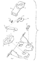
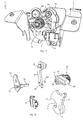
- the in FIG. 1 shown in an exploded view of the motor vehicle door closure 1 according to the first embodiment comprises interconnectable housing elements 3 and 4, a rotary latch 5 which is rotatably mounted about an axis of rotation 6 on the housing element 2 and a rotary latch jaw 7, in which the closing element 2 engages.
- the rotary latch 5 is characterized by a in FIG.
- the pawl 9 is connected via a rotary joint 12 with a motion element not shown in detail for the first embodiment drive element.
- the rotary joint 12 is rotatably mounted on the housing element 4 about a rotation axis (pivot point 13).
- a bolt-shaped connecting element is mounted as a rotation axis 14 for the pawl 9, which is arranged radially offset from the pivot point 13 on the pivot joint 12 and attached thereto.
- the connecting element in the form of the axis of rotation 14 connects the coupled to the drive element pivot 12 with a arranged in the region of the rotation axis 14 coupling portion 15 of the pawl 9, so that the pivot joint 12, the pawl 8 between the engaged position and a release position in which the pawl 9 with the catch 5 is disengaged moves.
- the pawl 9 is thus pivotally connected by means of the connecting element or the axis of rotation 14 the rotary joint 12 radially offset from the pivot point 13 stored.
- the rotary latch 5 can move or rotate in the direction of the open position.
- the pawl 9 is biased in the direction of the engagement position, which, for example, by means of an example only in FIG FIG. 3 It is sufficient if the area of the latching portion 10 of the pawl 9 is urged by the spring force in the engaged position and thus in the direction of the rotary latch 5 and the latching arm 11 of the rotary latch 5.
- the invention provides that the coupled to the drive element pivot 12 moves the pawl 9 during movement from the engaged position in the direction of the release position in that the rotary catch 5, which is still in engagement with the pawl 9 during this movement, moves in the direction of the open position.
- the coupled with the catch 5 pawl 9 acts here as a delay means to delay the speed of opening the movement, in particular the rotational movement of the catch 5 to release the closing element 2 and simultaneously avoiding the opening noise and slow down.
- FIGS. 4 to 7 is a movement curve 17 of the rotation axis 14 and the coupling portion 15 which is connected via the rotation axis 14 and the rotary joint 12 with the drive element, shown in dashed lines.
- the movement curve 17 essentially corresponds to the control recesses 18 and 19, which are formed in the housing elements 3 and 4. From the movement curve 17, it can be seen that the movement of the coupling portion 15 of the pawl 9, which is pivotally mounted on the rotation axis 14, from the position of engagement in the direction of the release position is a circular-segment-shaped movement, which is shown in FIGS FIGS. 4 to 7 counterclockwise in the direction of arrow A.
- a rotational movement or rotational movement of the rotary joint 12 about the pivot point 13 causes the coupling section 15 or the rotational axis 14 of the pawl 8 to be moved along a circular section.
- the control recesses 18 and 19 formed in the housing elements 3 and 4 can additionally guide the movement of the axis of rotation 14.
- the control recesses 18 and 19 are dispensable, so that they can be omitted in the motor vehicle door lock or rear lock 1 according to the invention.
- the pawl 8 is moved by the rotary joint 12 during movement from the engaged position in the direction of the release position such that in this movement with the pawl 9 still engaged rotary latch 5 is moved in the direction of the open position ,
- the rotary joint 12, which is coupled to the drive element, is rotated to open the motor vehicle door lock or the rear lock 1 such that the pawl 9 or at least a portion of the pawl 9 (ie the latching portion 10) initially during movement from the engaged position in the direction the release position is moved substantially tangentially with respect to the rotary latch 5 and then, in order to disengage the pawl 9 and the catch 5, is moved substantially radially away from the rotary latch 5.
- the latching portion 10, which is in the engaged position of the pawl 9 with the rotary latch 5 is engaged, is guided by means of a guide member 20 movement.
- the guide member 20 is on the housing member 3 of the motor vehicle door lock or rear lock langordnet and pivotally mounted about an axis 21 thereto.
- the guide element 20 has a guide recess 22 with two opposing abutment surfaces, which leads or controls a movement of the engageable with the catch 5 locking portion 10 of the pawl 9 toward the rotary latch 5 or away from the rotary latch.
- the movement of a control pin 23 can be performed, which is formed in the region of the latching portion 10 of the pawl 9 (see FIGS. 4 and 8 ).
- the movement of the guide element 20 itself can be achieved by a movement limiting recess 24 formed in the housing element 3 (see FIG FIG. 1 ) be limited.
- the latching portion 10 of the pawl 9 may, as mentioned above, be biased in the direction of the engagement position by means of the spring element 16, so that the formed in the region of the locking portion 10 control pin 23 during the in the FIGS. 4 to 7 shown movement is urged radially in the direction of the rotary latch 5 at the extreme end of the formed in the guide member 20 guide recess 22.
- a radial movement away from the rotary latch 5 could be effected by itself.
- an outer portion of the rotary latch 5 could have a radial projection 25, as in FIG FIG. 4 indicated by dashed lines or shown.
- the radial projection 25 would arrive at sufficient rotation in abutment with the pawl 9 and the Pawl 9 push away or deflect such that the locking portion 10 and the locking arm 11 are disengaged.
- FIG. 8 a position of the rear lock or the motor vehicle door lock 1 is shown during the closing operation, in which the coupling portion 15 of the pawl 9 is again in the engaged position, whereas the locking portion 10 of the pawl 9 is disposed radially away from the rotary latch 5, wherein the control pin 23rd a central position in the guide recess 22 of the guide member 20 occupies. Due to the fact that the control pin 23 of the locking portion 10 can be urged radially against the force of the spring element 16 in the guide recess 22 of the guide member 20 away from the rotary latch 5, it is possible that the rotary latch 5 rotates in the direction of arrow B during the closing operation and in this movement, the latching arm 11 slides past the latching section 10.
- the bias of the pawl 9 ensures that when the latching arm 11 has passed the latching portion 10, both interlock or that the latching portion 10 then pushes over the latching arm 11 and ensures engagement of pawl 9 and 5 catch, so that in FIG. 4 shown closed position is taken again.
- the process of closing but should not be considered here in detail, because the invention is primarily directed to the processes when opening the motor vehicle door lock or the rear lock. 1
- FIGS. 9 to 13 the motor vehicle door lock or the rear lock 1 according to the second embodiment is shown.
- the motor vehicle door lock or the rear lock 1 according to the second embodiment - as well as the first embodiment - the housing element 3, which for reasons of clarity, only in FIG. 9 is shown, around and on the axis of rotation 6 rotatably mounted rotary latch 5 with the rotary latch jaw 7, in which the closing element 2 is arranged in the engaged position, and with the locking arm 11, which with the locking portion 10 of the pawl 9 in the engaged position is engaged, and with a drive element 26 (see, eg FIG.
- the pawl 9 is connected to the rotary joint 13 coupled for movement.
- this coupling between the first and second embodiments, which will be discussed later in the description of the second embodiment.
- the coupling section 15 of the pawl 9 is mounted or mounted pivotably on the rotary joint 12 via the axis of rotation 14.
- the rotation axis 14 is not stationary in contrast to the rotation axis 6, but moves during the movement of the pawl 9 in the direction of the release position relative to the axis of rotation 6 of the rotary latch 5 translationally along in the FIGS. 12 and 13
- the coupling section 15 of the pawl 9 undergoes a circular segment-shaped movement which is not a rotational movement but a substantially translational movement with respect to the rotary latch 5.
- the first end 29 of the push rod 28 is mounted radially offset from a rotational axis 30 of the drive element 26 on a radial shoulder 31 of the drive element 26 on this rotatable or pivotable.
- the push rod 28 is slightly bent, wherein a second end 32 of the push rod 28 receives the movement coupled to the coupling portion 15 of the pawl 9 pivot 12 and the rotational axis 14 of the pawl 9.
- the rotary joint 12 is rotatably mounted on the attached to the housing element 3 pivot point 13.
- the movement of the second end 32 of the push rod 28 is guided by the rotary joint 12 along the movement curve 17, so that thereby also the rotation axis 14 and the coupling portion 15 of the pawl 9, which are coupled to the second end 32 of the push rod 28, along move the movement curve 17.
- the coupling portion 15 of the pawl 9 undergoes a substantially circular segment-shaped movement.
- the movement of the latching section 10 out of the engagement position in the direction of the release position is in a first movement section a movement of the latching section 10 substantially tangential with respect to the rotary latch 5, which is characterized by the vertical course of the movement path 33.
- the pawl 9 is still engaged with the rotary latch 5 in engagement.
- FIGS. 14 to 22 is a motor vehicle door lock or a rear lock 1 shown according to a third embodiment.
- the rear lock 1 according to the third embodiment includes only in the FIGS. 14 to 22 schematically illustrated closing element 2, which may be attached to a vehicle frame, when the rear lock 1 is attached to the tailgate. It is also conceivable, of course, that the closing element 2 can be attached to the tailgate and the rear lock 1 to the vehicle frame.
- the motor vehicle door lock 1 further comprises the only in FIG. 14 shown housing element 3, in which further components of the motor vehicle door lock 1 added, under and are attached. For clarity, the housing element 3 in the FIGS. 15 to 22 not shown further.
- the motor vehicle door lock 1 additionally comprises the rotary latch 5, which is rotatably mounted about the axis of rotation 6 on the housing element 3 and which has the rotary latch jaw 7, in which the closing element 2 engages in the closed position.
- the catch 5 is biased by a spring element not shown in more detail or spring (force) acted upon or spring preloaded that it strives to, for example, in FIG. 17 shown closed position or closed position to rotate clockwise about the axis of rotation 6, so that the rotary latch 5 in the open position, the closing element 2 with respect to FIG. 22 releases downwards.
- the rotary latch 5 engages in the closed position, the closing element 2, wherein it is biased in the direction of the closing element 2 releasing open position.
- the pawl 9, which is at least pivoted to open the rear lock (motor vehicle door lock) 1 and is brought out of engagement with the rotary latch 5, with the interposition of the rotary joint (articulated lever) 12 is connected to the drive member 26 and coupled for movement, wherein the drive member 26 can be driven by a motor, not shown, for example with worm gear with helical teeth.
- drive member 26 is shown partially cut to also represent components that are located lying behind the drive element 26.
- the rotary joint or the articulated lever 12 is plate-shaped or disc-shaped and rotatably mounted on the housing element 3 about the pivot point 13.
- the drive element 26 moves the pawl 9 such that during this movement with the pawl 9 still engaged rotary latch 5 is moved or moved in the direction of the open position.
- the movement of the drive member 26 is a rotational movement, during the movement of the pawl 9 from the engaged position in the direction of the release position with respect to the rotary latch 5 substantially tangential movement of the pawl 9 and then to the pawl 9 and the catch 5 except To bring about a substantially radially away from the rotary latch 5 pioneering movement of the pawl 9 causes.
- the pin 39 and the coupling portion 15 and the rotational axis 14 of the pawl 9 are each radially offset from the pivot point 13 of the pivot joint (articulated lever) 12 at the pivot (articulated lever) 12 is arranged and mounted.
- a rotation of the drive member 26 in a clockwise direction (with respect to the FIGS. 17 to 21 ) in the direction of the arrow D causes a rotational movement of the rotary joint (articulated lever) 12 also in a clockwise direction (in the direction of arrow C), whereby the eccentrically or radially offset to the pivot point 13 and rotatably mounted on the rotary joint (articulated lever) 12 rotational axis 14th the pawl 9 in the region of the coupling portion 15 rotates and moves in a circle-shaped manner about the pivot point 13 of the swivel joint (articulated lever) 12, whereas the latching portion 10 of the pawl 9 of the above-described tangential and then radial movement curve 33 (see, for example FIG. 17 ) follows during the opening process.
- a movement of the pin 39 rotates directly the pivot (articulated lever) 12 and indirectly the coupling portion 15 of the pawl.
- the drive element 26 initially absorbs kinetic energy before the load acts on the transmission lever 38 for moving the pawl 9.
- the drive element 26 moves from a starting start position AS in a Anfahrendposition AE, the drive element 26 moves only after reaching the Anfahrendposition AE the pawl 9 from the engaged position in the direction of the release position.
- the starting start position AS and the starting end position AE are in FIG. 18 indicated, wherein the dashed line represents the position of the transmission lever 38 in the starting start position AS.
- the drive element 26 Upon movement of the drive element 26 between the starting start position AS and the Anfahrendposition AE standing in operative connection with the pawl 9 pin 39 is not moved. Rather, the drive element 26 rotates from the starting start position AS, to receive sufficient momentum or sufficient kinetic energy until reaching the Anfahrendposition AE so that the pawl 9 can be moved in the direction of the release position , Thus, the pin 39 is not moved during this rotational movement of the drive member 26, whereby the drive member 26 would be charged, the slot 40 has a neutral radius, which is synonymous with a freewheeling portion 41 (see FIG. 16 ).
- the freewheeling section 41 extends in a circular section in an angular range ⁇ between 18 ° and 32 ° about the axis of rotation (Fulcrum) 30 of the drive element 26.
- the freewheel defining angle range ⁇ is approximately 20 °, wherein the total opening rotational movement of the drive element 26 about the rotation axis (pivot point) 30 is less than 180 °.
- the drive element 26 the movement of the pawl 9 from the engaged position in the intermediate position driving and braking from the intermediate position into the release position is formed, the drive element 26 acts behind the dead center position as a brake, the movement of the pawl 9 completely by the drive element 26th is guided from the engaged position to the release position and the drive member 26 holds the pawl 9 quasi after exceeding the intermediate position or the dead center and prevents the movement of the pawl 9 is accelerated.
- the latching section 10 performs a substantially tangential movement with respect to the rotary latch 5, wherein the pawl 9 continues to engage with the rotary latch 5, but after the dead center has been exceeded turns in the direction of the open position.
- the latching portion 10 of the pawl 9 is moved radially away from the rotary latch 5, to disengage the pawl 9 and the rotary latch 5.
- the motor vehicle door lock 1 comprises a guide element 44, which in FIG. 15 is shown in a single part representation. By the guide member 44, it is the pawl 9 when returning from the open position into the closed position only then possible to engage in the catch when the axis of rotation 14 of the pawl substantially in FIG. 17 shown position along the circular segment-shaped movement curve 17 has taken.
- the swivel joint 12 or the push rod 28 or the drive element 26 may be the delay means.
- any combination of the three components (pivot 12, push rod 28, drive member 26) or all three components together can represent the delay means to the rotational speed of the rotary latch 5 during the opening process at least initially, ie for example in a first third of the movement from the closed position in Direction of the open position, to delay.
- the delay is controlled, ie the rotational speed is controlled by the delay means, including in the three preceding Embodiments the pawl 9 is used, via which the rotary latch 5 is coupled to the / the delay means.
- the rotary joint 12 which is rotatable about the pivot point 13, wherein the pivotable about the rotation axis 14 pawl 9 is mounted on the pivot 12 radially offset from the pivot point 13.
- the push rod 28 may be the retarder alone or together with the pivot 12.
- a first end 29 of the push rod 28 is pivotally and radially offset from the rotational axis 30 of the rotary lever or radial shoulder 31 coupled thereto, wherein the second end 32 of the push rod 28 is coupled to the pivot 12 in the region of the axis of rotation 14 of the pawl 9 so that during movement of the push rod 28, the rotational axis 14 of the pawl 9 along a circular-segment-shaped movement path 17 moves about the pivot point 13 of the rotary joint 12.
- the drive member 26 may be provided as a delay means, the drive member 26 causes the movement of the pivot joint 12 about the pivot point 13 in the movement of the pawl 9 from the engaged position to the release position around and controlled and delayed.
- a damping element which may in particular be a mechanical, hydraulic or pneumatic damping element, serve as an alternative delay means.
- Such serving as a delay means damping element would then act directly on the rotary latch 5 and the rotational movement of the rotary latch 5 from the closed position to possibly delay the open position linear, where it may be sufficient in terms of avoiding the disturbing opening noise when the delay means the first third of Rotary movement of the rotary latch 5 delays the degradation of the bias of the tailgate due to a compressed seal.
- the delay means is designed as acting on the rotary latch 5 damping element, the delayed movement of the rotary latch 5 is decoupled to release the closing element 2 of the pawl 9. Only the pawl 9 must be disengaged from the catch 5, which can be done at the beginning of the opening process, in which case, after the pawl 9 is no longer engaged with the rotary latch 5, that damping element caused by a spring element rotational movement of the rotary latch. 5 delayed accordingly.
- the invention includes everything that is contained in the description and / or illustrated in the drawing, including what is obvious to the person skilled in the art, which deviates from the specific exemplary embodiments.
Abstract
Description
Die Erfindung richtet sich auf ein Heckschloss für ein Kraftfahrzeug, mit einer in Schließstellung ein Schließelement umgreifenden und in Richtung einer das Schließelement freigebenden Offenstellung vorgespannten Drehfalle und einer Sperrklinke, die zwischen einer Freigabestellung und einer Eingriffsstellung bewegbar ist, wobei die Sperrklinke in der Freigabestellung mit der Drehfalle außer Eingriff steht und in der Eingriffsstellung mit der Drehfalle derart in Eingriff steht, das die Drehfalle an einer Bewegung in Richtung der Offenstellung gehindert ist.The invention is directed to a rear lock for a motor vehicle, with a locking element in the closed position and in the direction of a closing element releasing open position biased catch and a pawl which is movable between a release position and an engagement position, wherein the pawl in the release position with the The catch is disengaged and engaged in the engaged position with the catch in such a way that the catch is prevented from moving in the direction of the open position.
Ein Heckschloss der eingangs genannten Art, welches ganz allgemein als Kraftfahrzeugtürverschluss bezeichnet werden kann, ist beispielsweise aus der
In Schließstellung der Heckklappe ist diese beispielsweise gegen eine Dichtung vorgespannt. Unter Vorspannung ist hierbei zu verstehen, dass der von einer Klappendichtung verursachte Dichtungsgegendruck dem Schließen der Kraftfahrzeugklappe entgegenwirkt. Dadurch herrscht aufgrund der von der Heckklappe komprimierten Dichtung ein hoher Druck in Öffnungsrichtung der Heckklappe. Wenn die Sperrklinke mit der Drehfalle außer Eingriff gelangt, baut sich der durch die Dichtung aufgebaute Druck in Form eines sogenannten Entlastungsschlags schnell ab und die Heckklappe bewegt sich schlag- und ruckartig in Richtung der Öffnungsrichtung, was sich in einem akustisch hörbaren Öffnungsgeräusch negativ bemerkbar macht und zu Einbußen im Komfort führt.In the closed position of the tailgate this is biased for example against a seal. Under bias is to be understood here that the sealing gasket pressure caused by a flap seal counteracts the closing of the motor vehicle door. As a result, there is a high pressure in the opening direction of the tailgate due to the compressed from the tailgate seal. When the pawl is disengaged from the catch, the pressure built up by the seal builds up rapidly in the form of a so-called unloading stroke and the tailgate moves abruptly and jerkily in the direction of the opening direction, which is negatively noticeable in an acoustically audible opening noise and leads to losses in comfort.
Der Erfindung liegt die Aufgabe zugrunde eine Lösung zu schaffen, die auf konstruktiv einfache Weise und kostengünstig ein Heckschloss bzw. einen Kraftfahrzeugtürverschluss bereitstellt, bei dem das Öffnungsgeräusch auf ein Minimum reduziert ist, zumindest aber bei dem der Öffnungsvorgang kein deutlich hörbares und den Komfort negativ beeinträchtigendes Geräusch erzeugt.The invention has for its object to provide a solution that provides a rear lock or a motor vehicle door lock in a structurally simple manner and cost, in which the opening noise is reduced to a minimum, or at least in which the opening process no clearly audible and the comfort negatively impairing Noise generated.
Bei einem Heckschloss der eingangs bezeichneten Art und auch allgemein bei einem Kraftfahrzeugtürverschluss wird die Aufgabe erfindungsgemäß dadurch gelöst, dass Verzögerungsmittel vorgesehen sind, die mit der Drehfalle gekoppelt sind, um eine Geschwindigkeit einer Bewegung der Drehfalle zur Freigabe des Schließelementes zu verzögern. Dabei kann die Bewegung der Drehfalle bei dem erfindungsgemäßen Heckschloss eine Drehung bzw. Drehbewegung sein. Auch können es mehrere Verzögerungsmittel oder auch nur ein einziges Verzögerungsmittel sein. Im weiteren Verlauf der Beschreibung ist daher gleichzeitig die Ein- und Mehrzahl für Verzögerungsmittel angesprochen.In a rear lock of the type described above and also generally in a motor vehicle door lock, the object is achieved in that delay means are provided which are coupled to the rotary latch to delay a speed of movement of the rotary latch to release the closing element. In this case, the movement of the rotary latch in the rear lock according to the invention can be a rotation or rotational movement. It may also be several delay means or even a single delay means. In the further course of the description, therefore, the input and the plurality of delay means are simultaneously addressed.
Vorteilhafte und zweckmäßige Ausgestaltungen und Weiterbildungen der Erfindung ergeben sich aus den Unteransprüchen.Advantageous and expedient refinements and developments of the invention will become apparent from the dependent claims.
Durch die Erfindung wird ein Heckschloss, aber auch ganz allgemein ein Kraftfahrzeugtürverschluss, zur Verfügung gestellt, welches zur Erhöhung des Komforts und der Qualität des Verschlusses und dessen Funktionsweise beiträgt. Der erfindungsgemäße Kraftfahrzeugtürverschluss, im speziellen das Heckschloss, zeichnet sich durch eine funktionsgerechte Konstruktion aus und weist einen einfachen und kostengünstigen Aufbau auf. Durch die verzögerte Bewegung der Drehfalle und der Auslösemechanik des Kraftfahrzeugtürverschlusses bzw. des Heckschlosses gemäß der vorliegenden Erfindung stehen die Sperrklinke und die Drehfalle während eines Bewegungsvorgangs der Sperrklinke in Richtung der Freigabestellung nach wie vor in Eingriff. Zwar ermöglicht diese Bewegung nicht das Öffnen der Heckklappe. Jedoch wird durch diese (erste bzw. anfängliche) Bewegung beim Öffnungsvorgang die Vorspannung der Heckklappe abgebaut, da die definierte und verzögerte Bewegung der Sperrklinke eine Relativbewegung zwischen dem Kraftfahrzeugtürverschluss und dem Schließelement und somit eine Entlastung der Heckklappe bewirkt, wobei die Drehfalle um eine vorbestimmte Drehbewegung in Offenstellung gedreht wird. Dadurch wird der Heckklappe letztlich ermöglicht, sich um einen definierten Hub relativ zum Schließelement zu bewegen, wodurch die Vorspannung und der Druck genommen ist, welcher zuvor bei den aus dem Stand der Technik bekannten Kraftfahrzeugtürverschlüssen für das akustisch wahrnehmbare und störende Öffnungsgeräusch verantwortlich war. Demnach sieht die Erfindung vor, dass die Vorspannung zwischen Heckklappe bzw. Kraftfahrzeugtürverschluss und Schließelement reduziert wird, bevor die Sperrklinke und die Drehfalle außer Eingriff gebracht werden.By the invention, a rear lock, but also quite generally a motor vehicle door lock, available which enhances the comfort and quality of the closure and its operation. The motor vehicle door lock according to the invention, in particular the rear lock, is characterized by a functional design and has a simple and inexpensive construction. Due to the delayed movement of the rotary latch and the trigger mechanism of the motor vehicle door lock and the rear lock according to the present invention, the pawl and the rotary latch during a movement operation of the pawl in the direction of the release position are still in engagement. Although this movement does not allow the opening of the tailgate. However, by this (initial or initial) movement during the opening process, the bias of the tailgate degrades because the defined and delayed movement of the pawl causes a relative movement between the motor vehicle door lock and the closing element and thus relieving the tailgate, wherein the rotary latch to a predetermined rotational movement is turned in the open position. This ultimately allows the tailgate to move a defined stroke relative to the closure member, thereby relieving the preload and pressure previously responsible for the acoustically perceptible and disturbing opening noise in prior art automotive door closures known in the art. Accordingly, the invention provides that the bias between the tailgate or motor vehicle door lock and closing element is reduced before the pawl and the rotary latch are disengaged.
Die Erfindung sieht auch einen Kraftfahrzeugtürverschluss vor mit einer in Schließstellung ein Schließelement umgreifenden und in Richtung einer das Schließelement freigebenden Offenstellung vorgespannten Drehfalle, einer Sperrklinke, die in einer Eingriffsstellung mit der Drehfalle derart in Eingriff steht, dass die Drehfalle an einer Bewegung in Richtung der Offenstellung gehindert ist, und einem Antriebselement, mit dem ein Kopplungsabschnitt der Sperrklinke bewegungsgekoppelt ist und das die Sperrklinke zwischen der Eingriffsstellung und einer Freigabestellung bewegt, in welcher die Sperrklinke mit der Drehfalle außer Eingriff steht, so dass sich die Drehfalle in Richtung der Offenstellung bewegen kann, wobei die Aufgabe hierbei erfindungsgemäß dadurch gelöst wird, dass das Antriebselement die Sperrklinke während der Bewegung aus der Eingriffsstellung in Richtung der Freigabestellung derart bewegt, dass sich die bei dieser Bewegung mit der Sperrklinke nach wie vor in Eingriff stehende Drehfalle in Richtung der Offenstellung bewegt.The invention also provides a motor vehicle door lock with a locking element in the closed position and in the direction of an open position releasing the open position biased latch, a pawl which engages in an engaged position with the rotary latch in such a manner that the rotary latch on a movement in the direction of the open position is prevented, and a drive element, with which a coupling portion of the pawl is coupled for movement and which the pawl between the engaged position and a Release position moves, in which the pawl with the catch is disengaged, so that the catch can move in the direction of the open position, the task here is inventively achieved in that the drive element, the pawl during movement from the engaged position in the direction of the release position moved so that during this movement with the pawl still engaged rotary catch moves in the direction of the open position.
Ebenso sieht die Erfindung ein Verfahren zum Öffnen eines Kraftfahrzeugtürverschlusses (insbesondere eines Heckschlosses) vor, wobei der Kraftfahrzeugtürverschluss eine in Schließstellung ein Schließelement umgreifende und in Richtung einer das Schließelement freigebenden Offenstellung vorgespannte Drehfalle, eine Sperrklinke, die in einer Einraststellung mit der Drehfalle derart in Eingriff steht, dass die Drehfalle an einer Bewegung in Richtung der Offenstellung gehindert ist, und ein Antriebselement, mit dem ein Kopplungsabschnitt der Sperrklinke bewegungsgekoppelt ist und das die Sperrklinke zwischen der Eingriffsstellung und einer Freigabestellung bewegt, in welcher die Sperrklinke mit der Drehfalle außer Eingriff steht, so dass sich die Drehfalle in Richtung der Offenstellung bewegen kann, aufweist, wobei die Sperrklinke und die Drehfalle zum Öffnen außer Eingriff gebracht werden, indem die Sperrklinke zumindest abschnittsweise von der Drehfalle weggeschwenkt wird, wobei die Sperrklinke von dem Antriebselement während der Bewegung aus der Eingriffsstellung in Richtung der Freigabestellung derart bewegt wird, dass die bei dieser Bewegung mit der Sperrklinke nach wie vor in Eingriff stehende Drehfalle in Richtung der Offenstellung bewegt wird.Likewise, the invention provides a method for opening a motor vehicle door lock (in particular a rear lock), wherein the motor vehicle door lock in the closed position a closing element encompassing and in the direction of the closure member releasing open position biased rotary latch, a pawl in a latching position with the catch in such a manner is that the catch is prevented from moving in the direction of the open position, and a drive element to which a coupling portion of the pawl is coupled and which moves the pawl between the engaged position and a release position in which the pawl is disengaged from the catch, so that the catch can move in the direction of the open position, wherein the pawl and the catch are disengaged for opening by the pawl is at least partially pivoted away from the rotary latch, wherein the pawl is moved by the drive element during movement from the engagement position in the direction of the release position such that during this movement with the pawl still engaged rotary catch is moved in the direction of the open position.
In Ausgestaltung des erfindungsgemäßen Heckschlosses ist es dann von besonderem Vorteil, dass die Drehfalle über die Sperrklinke mit den Verzögerungsmitteln derart gekoppelt ist, dass die Geschwindigkeit der Bewegung der Drehfalle zur Freigabe der Drehfalle kontrolliert erfolgt. Es handelt sich somit wohl gemerkt um eine kontrollierte Bewegung der Drehfalle, die durch die Kopplung mit der Sperrklinke bewirkt wird.In an embodiment of the rear lock according to the invention, it is then of particular advantage that the rotary latch is coupled via the pawl with the delay means such that the speed of movement of the rotary latch for releasing the rotary latch is controlled. It is thus well noted a controlled movement of the catch, which is caused by the coupling with the pawl.
Die kontrollierte Bewegung der Sperrklinke lässt sich in Ausgestaltung des erfindungsgemäßen Heckschlosses und auch eines allgemeinen Kraftfahrzeugtürverschlusses dadurch realisieren, dass ein um einen Drehpunkt drehbares Drehgelenk vorgesehen ist, wobei die um eine Rotationsachse drehbare Sperrklinke an dem Drehgelenk radial versetzt zu dessen Drehpunkt angebracht ist. Auf diese Weise ist es möglich, dass die Rotationsachse der Sperrklinke beispielsweise entlang einer kreisabschnittsförmigen Bewegungsbahn bewegt wird, ohne dass die Sperrklinke dabei außer Eingriff mit der Drehfalle gelangt.The controlled movement of the pawl can be realized in an embodiment of the rear lock according to the invention and also a general motor vehicle door closure that a pivotable about a pivot rotary joint is provided, which is rotatable about a rotation axis pawl mounted on the pivot radially offset from the pivot point. In this way, it is possible that the axis of rotation of the pawl, for example, is moved along a circular-segment-shaped trajectory, without the pawl thereby disengaged from the rotary latch.
Eine besonders kraftvolle und gleichzeitig effiziente Art der Bewegungskopplung der Sperrklinke lässt sich durch eine Art doppelten Kniehebel erzielen. Zu diesem Zweck sieht die Erfindung in Ausgestaltung eine Schubstange vor, von der ein erstes Ende schwenkbar und radial versetzt zu einer Rotationsachse eines Drehhebels bzw. Radialansatzes mit diesem gekoppelt ist und von der ein zweites Ende mit dem Drehgelenk im Bereich der Rotationsachse der Sperrklinke derart gekoppelt ist, dass sich bei Bewegung der Schubstange die Rotationsachse der Sperrklinke entlang einer kreisabschnittsförmigen Bewegungsbahn um den Drehpunkt des Drehgelenks bewegt. Somit ist ein erster Kniehebel durch das zweite Ende der Schubstange und das ortsfest gelagerte Drehgelenk definiert, wobei die Sperrklinke über die Rotationsachse mit dem Drehgelenk und mit der Schubstange gekoppelt ist. Ein zweiter Kniehebel ist dabei durch das erste Ende der Schubstange und dessen in Bezug auf die Rotationsachse exzentrische bzw. radial versetzte Kopplung mit dem Drehhebel definiert, so dass insgesamt ein doppelter Kniehebel vorliegt.A particularly powerful and at the same time efficient way of coupling the pawl can be achieved by a kind of double toggle lever. To this end, the invention provides in an embodiment of a push rod, of which a first end is pivotally and radially offset from a rotational axis of a rotary lever or radial approach is coupled thereto and coupled by a second end to the rotary joint in the region of the axis of rotation of the pawl such is that moves the axis of rotation of the pawl along a circular segment-shaped trajectory about the pivot point of the pivot joint during movement of the push rod. Thus, a first toggle lever is defined by the second end of the push rod and the fixedly mounted pivot, wherein the pawl is coupled via the rotation axis with the pivot and with the push rod. A second toggle lever is defined by the first end of the push rod and its eccentric or radially offset with respect to the axis of rotation coupling with the rotary lever, so that a total of a double toggle is present.
In weiterer Ausgestaltung des Heckschlosses und allgemein des Kraftfahrzeugtürverschlusses sieht die Erfindung vor, dass das Drehgelenk mit einem längenveränderlichen Hebel gekoppelt ist, der die Bewegung der Sperrklinke aus der Eingriffsstellung in eine Zwischenstellung antreibend und aus der Zwischenstellung in die Freigabestellung bremsend ausgebildet ist. Diese Ausgestaltung bewirkt, dass die Bewegung der Sperrklinke aus der Eingriffsstellung in die Freigabestellung und wieder zurück in die Eingriffsstellung durch ein von einem Motor angetriebenes Antriebselement kontrolliert geführt ist. Dabei dient das Antriebselement in einem ersten Bewegungsabschnitt aus der Eingriffsstellung bis zu einer Zwischenstellung als Antrieb für die Sperrklinke, wohingegen das Antriebselement bei der Bewegung der Sperrklinke aus der Zwischenstellung in die Freigabestellung als Bremse wirkt. Die Änderung der Wirkungsweise des Antriebselements ergibt sich daraus, dass die Zwischenstellung einen Lastwechsel für das Antriebselement definiert.In a further embodiment of the rear lock and in general of the motor vehicle door lock, the invention provides that the rotary joint is coupled with a variable-length lever, which is designed to brake the movement of the pawl from the engaged position to an intermediate position and braking from the intermediate position into the release position. This configuration causes the movement of the pawl from the engaged position to the release position and back to the engaged position by a motor-driven Drive element is controlled guided. The drive element is used in a first movement section from the engaged position to an intermediate position as a drive for the pawl, whereas the drive element acts as a brake during the movement of the pawl from the intermediate position to the release position. The change in the operation of the drive element results from the fact that the intermediate position defines a load change for the drive element.
In Ausgestaltung des Heckschlosses und auch allgemein des Kraftfahrzeugtürverschlusses sieht die Erfindung vor, dass die Zwischenstellung eine Totpunktlage der Sperrklinke ist, in welcher zumindest die auf die Sperrklinke einwirkende Kraft der Drehfalle und die Rotationsachse der Sperrklinke in einer Linie liegend angeordnet sind. Dabei beschreibt die Totpunktlage bzw. Zwischenstellung eine Position der Sperrklinke, die nur durch eine Kraft quer zur Linie, die von Rotationsachse und der auf die Sperrklinke einwirkenden Kraft der Drehfalle gebildet ist, geändert werden kann.In an embodiment of the rear lock and generally the motor vehicle door lock, the invention provides that the intermediate position is a dead center of the pawl, in which at least the force acting on the pawl force of the catch and the axis of rotation of the pawl are arranged lying in a line. In this case, the dead center position or intermediate position describes a position of the pawl, which can only be changed by a force transverse to the line, which is formed by the axis of rotation and the force acting on the pawl force of the rotary latch.
Das bereits vorstehend bei einigen Ausgestaltungen der Erfindung als mögliches ergänzendes Merkmal angesprochene Antriebselement kann gemäß erfindungsgemäßer Weiterbildung nun ganz konkret bei einer Bewegung der Sperrklinke aus der Eingriffsstellung in die Freigabestellung die Bewegung des Drehgelenks um die Drehachse herum bewirken.The above-mentioned in some embodiments of the invention as a possible complementary feature drive element can now according to the invention now quite concretely effect in a movement of the pawl from the engaged position to the release position, the movement of the rotary joint around the axis of rotation.
Von besonderem Vorteil ist es insbesondere, wenn die Verzögerungsmittel gleichzeitig eine Betätigung der Sperrklinke bewirken. Somit dienen die Verzögerungsmittel nicht nur der Verzögerung der Bewegung der Drehfalle, sondern darüber hinaus auch einer Betätigung und ggf. Bewegung der Sperrklinke.It is of particular advantage, in particular, if the delay means simultaneously effect an actuation of the pawl. Thus, the delay means serve not only the delay of the movement of the rotary latch, but also an actuation and possibly movement of the pawl.
Bei dem erfindungsgemäßen Heckschloss und auch bei dem allgemeinen Kraftfahrzeugtürverschluss gemäß der Erfindung können das Drehgelenk und/oder die Schubstange und/oder das Antriebselement das Verzögerungsmittel sein, was eine einfache und kostengünstige Konstruktion des Heckschlosses und des Kraftfahrzeugtürverschlusses ermöglicht.In the rear lock according to the invention and also in the general motor vehicle door lock according to the invention, the rotary joint and / or the push rod and / or the drive element may be the delay means, which allows a simple and inexpensive construction of the rear lock and the motor vehicle door lock.
Als eine Alternative zu der vorstehend angeführten Ausgestaltung des Verzögerungsmittels sieht die Erfindung vor, dass ein Dämpfungselement, insbesondere ein mechanisches, hydraulisches oder pneumatisches Dämpfungselement, als Verzögerungsmittel dient. Insbesondere kann es sich bei dem Dämpfungselement um ein Linear-Dämpfungselement handeln, wobei das Dämpfungselement nicht als Endanschlag zur Abfederung der Endbewegung der Drehfalle dient, sondern vielmehr die anfängliche Bewegung der Drehfalle dämpfen, bremsen und damit verzögern soll.As an alternative to the above-mentioned embodiment of the retarder, the invention provides a damping element, in particular a mechanical, hydraulic or pneumatic damping element, serves as a retarding means. In particular, the damping element may be a linear damping element, wherein the damping element does not serve as an end stop for cushioning the end movement of the rotary latch, but rather dampens, brakes and thereby delays the initial movement of the rotary latch.
Allgemein sieht die Erfindung für den vorstehend beschriebenen Kraftfahrzeugtürverschluss sowie für das Verfahren vor, dass die Bewegung des Antriebselements eine Drehbewegung ist, die während der Bewegung der Sperrklinke aus der Eingriffsstellung in Richtung der Freigabestellung eine in Bezug auf die Drehfalle im Wesentlichen tangentiale Bewegung der Sperrklinke und dann, um die Sperrklinke und die Drehfalle außer Eingriff zu bringen, eine im Wesentlichen radial von der Drehfalle wegweisende Bewegung der Sperrklinke bewirkt. Diese Bewegung bezieht sich auf einen Rastabschnitt der Sperrklinke, welcher in der Eingriffsstellung mit der Drehfalle in Eingriff steht. Mit anderen Worten wird das Antriebselement zum Öffnen des Kraftfahrzeugtürverschlusses derart gedreht, dass die Sperrklinke oder zumindest ein Abschnitt der Sperrklinke, d.h. der Rastabschnitt, zunächst während der Bewegung aus der Eingriffsstellung in Richtung der Freigabestellung im Wesentlichen tangential in Bezug auf die Drehfalle bewegt wird und dann, um die Sperrklinke und die Drehfalle außer Eingriff zu bringen, von der Drehfalle im Wesentlichen radial weg bewegt wird. Die beim Öffnungsvorgang des Kraftfahrzeugtürverschlusses ausgeführte Bewegung der Sperrklinke ist somit zweigeteilt bzw. besteht aus einer Bewegungsabfolge, bei welcher die Sperrklinke in wenigstens zwei verschiedene Raumrichtungen bewegt wird. Um in Schließposition zunächst den Druck von der Heckklappe zu nehmen bzw. die vorgespannte Heckklappe zu entlasten, erfolgt eine im Wesentlichen tangentiale Bewegung der Sperrklinke in Bezug auf die Drehfalle. Bei dieser Bewegung steht die Sperrklinke nach wie vor mit der Drehfalle in Eingriff, wobei jedoch in Abhängigkeit der tangentialen Distanz, um die die Sperrklinke bewegt wird, der Drehfalle eine Drehung in Offenstellung ermöglicht wird, wodurch sich der Druck der Heckklappe abbaut. Erst nach dem Druckabbau bzw. der Reduzierung der Vorspannung erfolgt dann mit Hilfe der radialen Seitwärtsbewegung der Sperrklinke das außer Eingriff bringen mit der Drehfalle, wodurch diese dann zur Öffnung der Heckklappe das Schließelement freigibt. Die sich aus wenigstens zwei Bewegungen in unterschiedliche Raumrichtungen zusammensetzende Öffnungsbewegung der Sperrklinke ermöglicht somit den Abbau der auf die Heckklappe in Schließstellung wirkenden Vorspannung, indem die Sperrklinke eine kontrollierte Bewegung der Heckklappe in Öffnungsrichtung für einen gewissen Hub bewirkt.In general, the invention for the motor vehicle door lock described above and for the method that the movement of the drive member is a rotational movement, during the movement of the pawl from the engaged position in the direction of the release position with respect to the rotary latch substantially tangential movement of the pawl and then, to disengage the pawl and the catch, causing a movement of the pawl that points substantially radially away from the catch. This movement refers to a latching portion of the pawl, which engages in the engaged position with the rotary latch. In other words, the drive element for opening the motor vehicle door lock is rotated such that the pawl or at least a portion of the pawl, ie the latching portion, initially during movement from the engaged position in the direction of the release position is moved substantially tangentially with respect to the rotary latch and then to disengage the pawl and the catch, is moved substantially radially away from the catch. The movement of the pawl executed during the opening process of the motor vehicle door lock is thus divided into two or consists of a sequence of movements in which the pawl is moved in at least two different spatial directions. To initially take the pressure from the tailgate in the closed position or to relieve the preloaded tailgate, there is a substantially tangential movement of the pawl with respect to the rotary latch. In this movement, the pawl is still engaged with the catch, but depending on the tangential distance to which the Pawl is moved, the rotary latch allows a rotation in the open position, whereby the pressure of the tailgate degrades. Only after the pressure reduction or the reduction of the bias is then carried out with the help of the radial sideways movement of the pawl disengage the catch, which then releases the closing element for opening the tailgate. The resulting from at least two movements in different directions in space opening movement of the pawl thus allows the degradation of acting on the tailgate in the closed position bias by the pawl causes a controlled movement of the tailgate in the opening direction for a certain stroke.
Zur Reduzierung des Öffnungsgeräusches durch Reduzierung der Vorspannung zwischen Heckklappe bzw. Kraftfahrzeugtürverschluss und Schließelement, bevor die Sperrklinke und die um eine Drehachse drehbar gelagerte Drehfalle außer Eingriff gebracht werden, sieht die Erfindung auch vor, dass sich die Rotationsachse der Sperrklinke während der Bewegung der Sperrklinke in Richtung der Freigabestellung relativ zur Drehachse der Drehfalle, vorzugsweise translatorisch, bewegt. Bei der Bewegung der Rotationsachse in Richtung der Drehachse steht die Sperrklinke zwar nach wie vor mit der Drehfalle in Eingriff, jedoch kann sich aufgrund der translatorischen und tangential zur Drehfalle verlaufenden Bewegung der Sperrklinke die Drehfalle in Richtung ihrer Offenstellung drehen.To reduce the opening noise by reducing the bias between the tailgate or vehicle door lock and closing element, before the pawl and the rotatably mounted about an axis of rotation rotary latch disengaged, the invention also provides that the axis of rotation of the pawl during the movement of the pawl in Direction of the release position relative to the axis of rotation of the rotary latch, preferably translationally moves. During the movement of the axis of rotation in the direction of the axis of rotation, the pawl is indeed still engaged with the rotary latch, however, can rotate due to the translational and tangential to the rotary latch movement of the pawl, the rotary latch in the direction of its open position.
Damit die Vorspannung, mit welcher die Heckklappe in Schließstellung vorgespannt ist, allmählich und nicht schlagartig abgebaut wird, ist es bei dem Heckschloss und Kraftfahrzeugtürverschluss weiter von Vorteil, wenn die Bewegung aus der Eingriffsstellung in Richtung der Freigabestellung der an dem Drehgelenk schwenk- bzw. drehbar angebrachten Rotationsachse der Sperrklinke eine kreisabschnittsförmige Bewegung ist. Denkbar sind beispielsweise viertelkreisförmige oder auch halbkreisförmige Bewegungen.Thus, the bias voltage with which the tailgate is biased in the closed position, is degraded gradually and not abruptly, it is in the rear lock and motor vehicle door lock further advantageous if the movement from the engaged position in the direction of the release position of the pivot on the pivot or rotatable attached axis of rotation of the pawl is a circular section-shaped movement. It is conceivable, for example, quarter-circle or semi-circular movements.
Eine konstruktiv besonders einfache Möglichkeit zur definierten Führung der Sperrklinke in die Freigabestellung besteht weiterhin darin, dass der in der Eingriffsstellung mit der Drehfalle in Eingriff stehende Rastabschnitt der Sperrklinke mit Hilfe eines Führungselements und/oder eines an der Sperrklinke angebrachten Steuerzapfens bewegungsgeführt ist. Bei dieser geführten Bewegung wird beim Öffnungsvorgang die Sperrklinke von der Drehfalle radial weg bewegt, wobei es von besonderem Vorteil ist, wenn lediglich der mit der Drehfalle in Eingriff stehende Abschnitt der Sperrklinke, d.h. der Rastabschnitt, und nicht die gesamte Sperrklinke von der Drehfalle weg bewegt wird.A structurally particularly simple way for defined guidance of the pawl in the release position continues to be that in the engaged position with the catch in engagement locking portion of the pawl is guided by means of a guide member and / or mounted on the pawl control pin movement. In this guided movement, the pawl is moved radially away from the rotary latch during the opening process, it being particularly advantageous if only the engaging with the catch portion of the pawl, ie the latching portion, and not the entire pawl moves away from the rotary latch becomes.
Eine besonders günstige Übertragung der Antriebskraft des Antriebselements auf die Sperrklinke ist durch einen Übertragungshebel möglich, welcher mit der Sperrklinke in Wirkverbindung steht. Erfindungsgemäß werden hierbei die durch einen Hebel gegebenen Vorteile hinsichtlich der Kraftübertragung genutzt.A particularly favorable transmission of the driving force of the drive element to the pawl is possible by a transmission lever which is in operative connection with the pawl. According to the invention, the advantages given by a lever in terms of power transmission are used here.
In weiterer Ausgestaltung ist dann erfindungsgemäß vorgesehen, dass der Übertragungshebel mit einem Langloch versehen ist, in welchem ein mit der Sperrklinke bewegungsgekoppelter Zapfen geführt ist. Die mechanische Kopplung von Zapfen und Übertragungshebel erinnert an eine Art Kulissenführung, wobei jedoch im Unterschied dazu der Übertragungshebel je nach Stellung, die von der Drehbewegung eines den Übertragungshebel drehenden Antriebselements ist, eine Zwangsbewegung des Zapfens im Langloch bewirkt. Die Hebelkraft ändert sich aufgrund des in dem Langloch verschieblich gehaltenen Zapfens, da insbesondere die Hebellänge des Übertragungshebels je nach Position des Zapfens variiert. Auf diese Weise stellt die Erfindung eine Art längenveränderlichen Hebel bereit.In a further embodiment according to the invention is then provided that the transmission lever is provided with a slot in which a movement-coupled with the pawl pin is guided. The mechanical coupling of pin and transmission lever is reminiscent of a kind of slotted guide, but in contrast, the transmission lever, depending on the position, which is caused by the rotational movement of the transmission lever rotating drive element, a forced movement of the pin in the slot. The leverage changes due to the pin slidably held in the slot, since in particular the lever length of the transmission lever varies depending on the position of the pin. In this way, the invention provides a kind of variable-length lever.
Um eine besonders effiziente Kraftübertragung der vom Antriebselement bereitgestellten Antriebskraft zu ermöglichen, sieht die Erfindung in Ausgestaltung vor, dass der um den Drehpunkt drehbar gelagerte Gelenkhebel eine Wirkverbindung zwischen dem Übertragungshebel und der Sperrklinke bildet, wobei der Zapfen und der Kopplungsabschnitt jeweils radial versetzt zu dem Drehpunkt des Gelenkhebels an dem Gelenkhebel angeordnet und angebracht sind, so dass eine Bewegung des Zapfens direkt den Gelenkhebel und indirekt die Rotationsachse drehbewegt.In order to enable a particularly efficient power transmission of the driving force provided by the drive element, the invention provides in an embodiment that the pivotally mounted about the pivot pivot lever forms an operative connection between the transmission lever and the pawl, wherein the pin and the coupling portion each offset radially to the pivot point the articulated lever is arranged on the toggle lever and are mounted so that a movement of the pin directly rotates the toggle lever and indirectly rotates the axis of rotation.
Schließlich ist in Ausgestaltung des erfindungsgemäßen Kraftfahrzeugtürverschlusses vorgesehen, dass die Sperrklinke in Richtung der Eingriffsstellung vorgespannt ist. Auf diese Weise ist die Sperrklinke dauerhaft in Richtung der Eingriffsstellung gedrängt, was beispielsweise mit Hilfe von wenigstens einem Federelement erreichbar ist, welches als Zug- oder Druckfeder ausgebildet sein kann. Dabei ist es ausreichend, wenn lediglich der Abschnitt der Sperrklinke vorgespannt ist, welcher mit der Drehfalle in Eingriff bringbar ist bzw. mit der Drehfalle in Eingriff steht.Finally, it is provided in an embodiment of the motor vehicle door lock according to the invention that the pawl is biased in the direction of the engagement position. In this way, the pawl is permanently urged in the direction of the engagement position, which can be achieved for example by means of at least one spring element, which may be formed as a tension or compression spring. It is sufficient if only the portion of the pawl is biased, which can be brought into engagement with the rotary latch or is in engagement with the rotary latch.
Es versteht sich, dass die vorstehend genannten und nachstehend noch zu erläuternden Merkmale nicht nur in der jeweils angegebenen Kombination, sondern auch in anderen Kombinationen oder in Alleinstellung verwendbar sind, ohne den Rahmen der vorliegenden Erfindung zu verlassen. Der Rahmen der Erfindung ist nur durch die Ansprüche definiert.It is understood that the features mentioned above and those yet to be explained can be used not only in the particular combination given, but also in other combinations or in isolation, without departing from the scope of the present invention. The scope of the invention is defined only by the claims.
Weitere Einzelheiten, Merkmale und Vorteile des Gegenstandes der Erfindung ergeben sich aus der nachfolgenden Beschreibung im Zusammenhang mit der Zeichnung, in der beispielhaft bevorzugte Ausführungsbeispiele der Erfindung dargestellt sind. In der Zeichnung zeigt:
-
Figur 1 -
Figur 2Kraftfahrzeugtürverschluss aus Figur 1 im zusammengebauten Zustand in perspektivischer Ansicht, -
Figur 3Figur 2 -
Figur 4 -
Figur 5 -
Figur 6 -
Figur 7 -
Figur 8 -
Figur 9 -
Figur 10 -
Figur 11Kraftfahrzeugtürverschluss aus Figur 10 in einer Einzelteildarstellung, -
Figur 12Kraftfahrzeugtürverschluss aus Figur 10 in Eingriffsstellung bzw. geschlossener Stellung, -
Figur 13Kraftfahrzeugtürverschluss aus Figur 10 in Freigabestellung bzw. geöffneter Stellung, -
Figur 14 -
Figur 15Figur 14 , -
Figur 16Figur 15 -
Figur 17Heckschloss aus Figur 14 in Schließposition in einer schematischen Darstellung, -
Figur 18Kraftfahrzeugtürverschluss aus Figur 14 in einem ersten Schritt einer Öffnungsbewegung in schematischer Darstellung, -
Figur 19Kraftfahrzeugtürverschluss aus Figur 14 in einem zweiten Schritt einer Öffnungsbewegung bzw. in einer Zwischenstellung in schematischer Darstellung, -
Figur 20Kraftfahrzeugtürverschluss aus Figur 14 in einem dritten Schritt einer Öffnungsbewegung in schematischer Darstellung, -
Figur 21Kraftfahrzeugtürverschluss aus Figur 14 in einem vierten Schritt einer Öffnungsbewegung in schematischer Darstellung und -
Figur 22Kraftfahrzeugtürverschluss aus Figur 14 in einer geöffneten Stellung in schematischer Darstellung.
-
FIG. 1 a motor vehicle door lock (rear lock) according to the invention according to a first embodiment in perspective Einzelteildarstellung, -
FIG. 2 the motor vehicle door lockFIG. 1 in assembled condition in perspective view, -
FIG. 3 a perspective rear view of the inFIG. 2 shown motor vehicle door lock, -
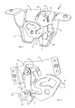
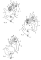
FIG. 4 the vehicle door latch according to the first embodiment in a closed position, -
FIG. 5 the motor vehicle door lock according to the first embodiment in a position between the closed and an open position, -
FIG. 6 the motor vehicle door lock according to the first embodiment in a further position between the closed and the open position, -
FIG. 7 the motor vehicle door lock according to the first embodiment in the open position, -
FIG. 8 the motor vehicle door lock according to the first embodiment when closing in a position shortly before reaching the closed position, -
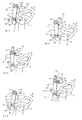
FIG. 9 a motor vehicle door lock (rear lock) according to the invention according to a second embodiment in front view, -
FIG. 10 the motor vehicle door lock according to the second embodiment in a rear view, -
FIG. 11 the motor vehicle door lockFIG. 10 in a single part presentation, -
FIG. 12 the motor vehicle door lockFIG. 10 in the engaged position or closed position, -
FIG. 13 the motor vehicle door lockFIG. 10 in release position or open position, -
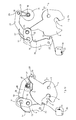
FIG. 14 a motor vehicle door lock (rear lock) according to the invention according to a third embodiment in front view, -
FIG. 15 an itemized view of a pawl, a hinge, a drive element, a guide element and a catch of the rear lockFIG. 14 . -
FIG. 16 this inFIG. 15 shown drive element in a sectional view, -
FIG. 17 the motor vehicle door lock or the rear lockFIG. 14 in closed position in a schematic representation, -
FIG. 18 the motor vehicle door lockFIG. 14 in a first step of an opening movement in a schematic representation, -
FIG. 19 the motor vehicle door lockFIG. 14 in a second step of an opening movement or in an intermediate position in a schematic representation, -
FIG. 20 the motor vehicle door lockFIG. 14 in a third step of an opening movement in a schematic representation, -
FIG. 21 the motor vehicle door lockFIG. 14 in a fourth step of an opening movement in a schematic representation and -
FIG. 22 the motor vehicle door lockFIG. 14 in an open position in a schematic representation.
Die
Während der Kraftfahrzeugtürverschluss 1 gemäß der ersten Ausführungsform in
Der an einer Heckklappe eines Kraftfahrzeugs montierte Kraftfahrzeugtürverschluss 1, was auch als Heckschloss 1 bezeichnet werden kann, greift zum Zwecke des Verschließens in ein schematisch und für die erste Ausführungsform lediglich in
Die Sperrklinke 9 ist über ein Drehgelenk 12 mit einem für die erste Ausführungsform nicht näher dargestelltes Antriebselement bewegungsgekoppelt verbunden. Das Drehgelenk 12 ist an dem Gehäuseelement 4 um eine Rotationsachse (Drehpunkt 13) drehbar gelagert. An dem Drehgelenk 12, welches zum Teil scheibenförmig ausgebildet ist, ist ein bolzenförmiges Verbindungselement als Rotationsachse 14 für die Sperrklinke 9 angebracht, welches radial versetzt zum Drehpunkt 13 an dem Drehgelenk 12 angeordnet und daran angebracht ist. Das Verbindungselement in Form der Rotationsachse 14 verbindet das mit dem Antriebselement gekoppelte Drehgelenk 12 mit einem im Bereich der Rotationsachse 14 angeordneten Kopplungsabschnitt 15 der Sperrklinke 9, so dass das Drehgelenk 12 die Sperrklinke 8 zwischen der Eingriffsstellung und einer Freigabestellung, in welcher die Sperrklinke 9 mit der Drehfalle 5 außer Eingriff gebracht ist, bewegt. Die Sperrklinke 9 ist somit mit Hilfe des Verbindungselementes bzw. der Rotationsachse 14 schwenkbar an dem Drehgelenk 12 radial versetzt zu dessen Drehpunkt 13 gelagert. Sobald sich die Sperrklinke 9 in der Freigabestellung befindet, kann sich die Drehfalle 5 in Richtung der Offenstellung bewegen bzw. drehen. Vorzugsweise ist die Sperrklinke 9 in Richtung der Eingriffsstellung vorgespannt, was beispielsweise mit Hilfe eines lediglich exemplarisch in
Um ein akustisch hörbares und störendes Öffnungsgeräusch der unter Vorspannung stehenden Heckklappe und damit des Kraftfahrzeugtürverschlusses bzw. Heckschlosses 1 zu unterbinden, ist erfindungsgemäß vorgesehen, dass das mit dem Antriebselement gekoppelte Drehgelenk 12 die Sperrklinke 9 während der Bewegung aus der Eingriffsstellung in Richtung der Freigabestellung derart bewegt, dass sich die bei dieser Bewegung mit der Sperrklinke 9 nach wie vor in Eingriff stehende bzw. befindende Drehfalle 5 in Richtung der Offenstellung bewegt. Die mit der Drehfalle 5 gekoppelte Sperrklinke 9 wirkt hierbei als Verzögerungsmittel, um die Öffnungsgeschwindigkeit der Bewegung, insbesondere der Drehbewegung, der Drehfalle 5 zur Freigabe des Schließelementes 2 und gleichzeitiger Vermeidung des Öffnungsgeräusches zu verzögern und zu verlangsamen. Durch diese (verzögerte) Bewegung wird die Vorspannung der Heckklappe abgebaut bzw. reduziert, da sich die Heckklappe aufgrund der beschriebenen Bewegungskopplung um einen definierten Hub aus der Verriegelungsstellung bewegen kann. Dieser Vorgang ist in den
Nachstehend werden die Vorgänge beim Öffnen des Kraftfahrzeugtürverschlusses bzw. des Heckschlosses 1 der ersten Ausführungsform erläutert.Hereinafter, the operations when opening the vehicle door lock and the
In den
Bei genauer Betrachtung der
Bei der Gesamtbewegung der Sperrklinke 9, wie es vorstehend beschrieben wurde, weicht die Bewegung des Kopplungsabschnitts 15, welcher aufgrund der Bewegungskopplung mit dem Drehgelenk 12 der kreissegmentförmigen bzw. kreisabschnittsförmigen Bewegungskurve 17 folgt, von der Bewegung des Rastabschnitts 10 der Sperrklinke 9 ab. Der Rastabschnitt 10, der in der Eingriffsstellung der Sperrklinke 9 mit der Drehfalle 5 in Eingriff steht, ist mit Hilfe eines Führungselements 20 bewegungsgeführt. Das Führungselement 20 ist an dem Gehäuseelement 3 des Kraftfahrzeugtürverschlusses bzw. Heckschlosses langeordnet und um eine Achse 21 schwenkbar daran gelagert. Ferner weist das Führungselement 20 eine Führungsausnehmung 22 mit zwei einander gegenüberliegenden Anschlagflächen auf, welche eine Bewegung des mit der Drehfalle 5 in Eingriff bringbaren Rastabschnitts 10 der Sperrklinke 9 hin zu der Drehfalle 5 oder weg von der Drehfalle 5 führt bzw. steuert. Insbesondere kann in der Führungsausnehmung 22 die Bewegung eines Steuerzapfens 23 geführt werden, der im Bereich des Rastabschnitts 10 der Sperrklinke 9 ausgebildet ist (siehe
Als Alternative zu dem Führungselement 20 könnte eine radiale Bewegung weg von der Drehfalle 5 von dieser selbst bewirkt werden. Zu diesem Zweck könnte ein Außenabschnitt der Drehfalle 5 einen Radialansatz 25 aufweisen, wie in
In
In den
Auch ist bei der zweiten Ausführungsform die Sperrklinke 9 mit dem Drehgelenk 13 bewegungsgekoppelt verbunden. Jedoch bestehen bei dieser Kopplung zwischen der ersten und zweiten Ausführungsform Unterschiede, auf die nachstehend bei der Beschreibung der zweiten Ausführungsform eingegangen wird.Also, in the second embodiment, the
Während die Drehfalle 5 mit Hilfe der ortsfesten Drehachse 6 an dem Gehäuseelement 3 drehbar gelagert ist, ist der Kopplungsabschnitt 15 der Sperrklinke 9 über die Rotationsachse 14 schwenkbar an dem Drehgelenk 12 angebracht bzw. gelagert. Die Rotationsachse 14 ist im Gegensatz zur Drehachse 6 nicht ortsfest, sondern bewegt sich während der Bewegung der Sperrklinke 9 in Richtung der Freigabestellung relativ zur Drehachse 6 der Drehfalle 5 translatorisch entlang der in den
In
Die Kraftübertragung des Antriebselements 26 erfolgt über den Radialansatz 31, der einem Übertragungshebel entspricht und die Kraft auf die Schubstange 28 überträgt, von der die Kraft dann weiter auf die Rotationsachse 14 bzw. den Kopplungsabschnitt 15 der Sperrklinke 9 übertragen wird. Die Schubstange 28 ist an einem am freien Ende des Radialansatzes 31 angeordneten Drehpunkt 36 drehbar gelagert. Dabei wird die übertragene Kraft von dem Drehgelenk 12 in eine definierte Bewegung des Kopplungsabschnitts 15 umgesetzt, wie es vorstehend beschrieben wurde. Hinsichtlich der Kraftübertragung definiert das Drehgelenk 12 einen ersten Kniehebel und der Radialansatz 31 einen zweiten Kniehebel, wodurch eine besonders kraftvolle Bewegungskopplung bewirkt wird. Der zweite Kniehebel sichert den ersten Kniehebel, insbesondere deshalb, da die Momente an dem zweiten Kniehebel sehr klein sind, so dass er sich durch geringe Kräfte gut sichern lässt. Aus Gründen der Sicherheit ist es ferner wünschenswert, dass der Kraftfahrzeugtürverschluss bzw. das Heckschloss 1 auch im Fall eines Fahrzeugunfalls in der geschlossenen Stellung verbleibt. Daher muss der Kraftfahrzeugtürverschluss 1 den bei einem Fahrzeugunfall vorherrschenden Beschleunigungskräften standhalten, so dass Sperrklinke 9 und Drehfalle 5 nicht außer Eingriff gelangen. Zu diesem Zweck weist die Sperrklinke 9 eine Beuge 35 (siehe
Der Kraftfahrzeugtürverschluss bzw. das Heckschloss 1 der ersten und zweiten Ausführungsform zeichnet sich dadurch aus, dass die Geräuschentwicklung beim Öffnungsvorgang auf ein Minimum reduziert ist und insbesondere das Geräusch beim Entlastungsschlag minimiert ist. Dies wird dadurch erreicht, dass beim Öffnungsvorgang die Sperrklinke 9 und die Drehfalle 5 derart zueinander bewegt werden, dass sich die Heckklappe und damit der Kraftfahrzeugtürverschluss 1 relativ zu dem Schließelement 2 entfernen kann, wodurch der auf die Heckklappe lastende Druck bzw. die Vorspannung der Heckklappe zunächst reduziert wird, bevor die Sperrklinke 9 und die Drehfalle 5 endgültig außer Eingriff gelangen, um das Schließelement 2 freizugeben. Insbesondere wird dies dadurch erreicht, indem beim Öffnungsvorgang das Drehgelenk 12, welches eine Schwenkachse 27 für die Sperrklinke 9 definiert, relativ zur Drehachse 6 der Drehfalle 5 bewegt wird, wodurch die zunächst tangentiale Bewegung zur Drehfalle 5 und dann die radial von der Drehfalle 5 wegweisende Bewegung des Rastabschnitts 9 der Sperrklinke 9 umgesetzt wird. Beim Öffnungsvorgang der zweiten Ausführungsform stellen das Drehgelenk 12, das Antriebselement 26 und die das Drehgelenk 12 mit dem Antriebselement 26 bewegungskoppelnde Schubstange 28 die Verzögerungsmittel dar, um die Geschwindigkeit der Drehbewegung der Drehfalle 5 zur Freigabe des Schließelementes 2 zu verzögern.The motor vehicle door lock or the
In den
Um den Kraftfahrzeugtürverschluss 1 in der in
Die Sperrklinke 9, die zum Öffnen des Heckschlosses (Kraftfahrzeugtürverschlusses) 1 zumindest verschwenkt wird und außer Eingriff mit der Drehfalle 5 gebracht wird, ist unter Zwischenschaltung des Drehgelenks (Gelenkhebels) 12 mit dem Antriebselement 26 verbunden bzw. bewegungsgekoppelt, wobei das Antriebselement 26 von einem nicht dargestellten Motor zum Beispiel mit Schneckengetriebe mit Schrägverzahnung angetrieben werden kann. Es sei angemerkt, dass das in den
Die Bewegung des Rastabschnitts 10 der Sperrklinke 9 aus ihrer in den
Das Antriebselement 26 ist über das Drehgelenk (den Gelenkhebel) 12 mit dem Kopplungsabschnitt 15 der Sperrklinke 9 bewegungsgekoppelt, so dass das Antriebselement 26 die Sperrklinke 9 bewegt. Dabei stellt hierbei das Drehgelenk 12 ein mit der Drehfalle 5 gekoppeltes Verzögerungsmittel dar, um die Geschwindigkeit der Drehbewegung der Drehfalle 5 zur Freigabe des Schließelementes 2 zu verzögern. Der Kopplungsabschnitt 15 entspricht auch in der dargestellten dritten Ausführungsform der Rotationsachse 14 der Sperrklinke 9. Er kann aber in alternativer Ausgestaltung auch an einem anderen Abschnitt der Sperrklinke 9 vorgesehen sein. In der Freigabestellung kann sich die Drehfalle 5 in Richtung der Offenstellung bewegen, um das Schließelement 2 freizugeben. Während der Bewegung aus der Eingriffsstellung in Richtung der Freigabestellung bewegt das Antriebselement 26 die Sperrklinke 9 derart, dass sich die bei dieser Bewegung mit der Sperrklinke 9 nach wie vor in Eingriff stehende Drehfalle 5 in Richtung der Offenstellung bewegt bzw. bewegt wird. Insbesondere ist die Bewegung des Antriebselements 26 eine Drehbewegung, die während der Bewegung der Sperrklinke 9 aus der Eingriffsstellung in Richtung der Freigabestellung eine in Bezug auf die Drehfalle 5 im Wesentlichen tangentiale Bewegung der Sperrklinke 9 und dann, um die Sperrklinke 9 und die Drehfalle 5 außer Eingriff zu bringen, eine im Wesentlichen radial von der Drehfalle 5 wegweisende Bewegung der Sperrklinke 9 bewirkt.The
Das in den
Eine Drehung des Antriebselementes 26 im Uhrzeigersinn (mit Bezug auf die
Für die dritte Ausführungsform des Heckschlosses bzw. des Kraftfahrzeugtürverschlusses 1 ist vorgesehen, dass das Antriebselement 26 zunächst kinetische Energie aufnimmt, bevor die Last zur Bewegung der Sperrklinke 9 auf den Übertragungshebel 38 wirkt. Zu diesem Zweck ist vorgesehen, dass sich zum Öffnen des Kraftfahrzeugtürverschlusses 1 das Antriebselement 26 aus einer Anfahrstartposition AS in eine Anfahrendposition AE bewegt, wobei das Antriebselement 26 erst nach Erreichen der Anfahrendposition AE die Sperrklinke 9 aus der Eingriffsstellung in Richtung der Freigabestellung bewegt. Die Anfahrstartposition AS und die Anfahrendposition AE sind in
Bei der Bewegung aus der Eingriffsstellung in die Freigabestellung durchläuft die Sperrklinke 9 eine Zwischenstellung, die in
Durch die auf die Sperrklinke 9 wirkende Kraft der vorgespannten Drehfalle 5 würde sich ohne die Antriebskraft des Antriebselementes 26 die Sperrklinke 9 immer wieder in die in
Erst wenn die in der
Mit Bezug auf die
In
Die Freigabestellung nimmt die Sperrklinke 9 bereits in
Wie vorstehend bereits beschrieben wurde, führt der Rastabschnitt 10 bei der Öffnungsbewegung in dem ersten Bewegungsabschnitt eine in Bezug auf die Drehfalle 5 im Wesentlichen tangentiale Bewegung durch, wobei die Sperrklinke 9 weiterhin mit der Drehfalle 5 in Eingriff steht, diese sich aber nach Überschreiten des Totpunktes in Richtung der Offenstellung dreht. In dem zweiten Bewegungsabschnitt wird dann der Rastabschnitt 10 der Sperrklinke 9 radial von der Drehfalle 5 weg bewegt, um die Sperrklinke 9 und die Drehfalle 5 außer Eingriff zu bringen. Um bei der Rückführung der Sperrklinke 9 eine mögliche Scheinschließung zu vermeiden, umfasst der Kraftfahrzeugtürverschluss 1 ein Führungselement 44, welches in
Wie vorstehend für das erfindungsgemäße Heckschloss bzw. den Kraftfahrzeugtürverschluss 1 ausgeführt, kann das Drehgelenk 12 oder die Schubstange 28 oder das Antriebselement 26 das Verzögerungsmittel sein. Auch irgendeine Kombination der drei Bauteile (Drehgelenk 12, Schubstange 28, Antriebselement 26) oder alle drei Bauteile zusammen können das Verzögerungsmittel darstellen, um die Drehgeschwindigkeit der Drehfalle 5 beim Öffnungsvorgang zumindest anfänglich, d.h. zum Beispiel in einem ersten Drittel der Bewegung aus der Schließstellung in Richtung der Offenstellung, zu verzögern. Dabei erfolgt die Verzögerung kontrolliert, d.h. die Drehgeschwindigkeit wird von dem Verzögerungsmittel kontrolliert, wozu in den drei vorstehenden Ausführungsbeispielen die Sperrklinke 9 dient, über welche die Drehfalle 5 mit den/dem Verzögerungsmittel gekoppelt ist.As stated above for the rear lock according to the invention or the motor
Beispielsweise kann als Verzögerungsmittel das Drehgelenk 12 dienen, das um den Drehpunkt 13 drehbar ist, wobei die um die Rotationsachse 14 drehbare Sperrklinke 9 an dem Drehgelenk 12 radial versetzt zu dessen Drehpunkt 13 angebracht ist.For example, serve as a retarding means, the rotary joint 12 which is rotatable about the
Alternativ kann die Schubstange 28 das Verzögerungsmittel allein oder zusammen mit dem Drehgelenk 12 sein. Ein erstes Ende 29 der Schubstange 28 ist schwenkbar und radial versetzt zu der Rotationsachse 30 des Drehhebels bzw. Radialansatzes 31 mit diesem gekoppelt, wobei das zweite Ende 32 der Schubstange 28 mit dem Drehgelenk 12 im Bereich der Rotationsachse 14 der Sperrklinke 9 so gekoppelt ist, dass sich bei Bewegung der Schubstange 28 die Rotationsachse 14 der Sperrklinke 9 entlang einer kreisabschnittsförmigen Bewegungsbahn 17 um den Drehpunkt 13 des Drehgelenks 12 bewegt.Alternatively, the
Andererseits kann das Drehgelenk 12 mit einem längenveränderlichen Hebel, der als Übertragungshebel 38 mit Langloch 30 ausgebildet ist, in welchem sich ein mit dem Drehgelenk 12 gekoppelter Zapfen bzw. Steuerzapfen 39 infolge einer Drehung des Übertragungshebels 38 verschieblich bewegt, gekoppelt sein, wobei der Hebel bzw. Übertragungshebel 38 die Bewegung der Sperrklinke 9 aus der Eingriffsstellung in eine Zwischenstellung antreibend und aus der Zwischenstellung in die Freigabestellung bremsend ausgebildet ist. Hierbei ist dann die die Zwischenstellung (gemäß dem dritten Ausführungsbeispiel) eine Totpunktlage der Sperrklinke 9, in welcher zumindest die auf die Sperrklinke 9 einwirkende Kraft der Drehfalle 5 und die Rotationsachse 14 der Sperrklinke 9 in einer Linie 43 liegend angeordnet sind.On the other hand, the swivel joint 12 may be coupled to a variable-length lever which is designed as a
Als andere Alternative kann das Antriebselement 26 als Verzögerungsmittel vorgesehen sein, wobei das Antriebselement 26 bei der Bewegung der Sperrklinke 9 aus der Eingriffsstellung in die Freigabestellung die Bewegung des Drehgelenks 12 um den Drehpunkt 13 herum bewirkt und kontrolliert sowie verzögert.As another alternative, the
Die vorstehend angeführten, unterschiedlichen Ausführungen führen allgemein zu dem Merkmal, dass die Verzögerungsmittel gleichzeitig eine Betätigung der Sperrklinke 9 bewirken.The above-mentioned, different embodiments generally lead to the feature that the delay means at the same time cause actuation of the
Die vorstehend beschriebene Erfindung ist selbstverständlich nicht auf die beschriebenen und dargestellten Ausführungsformen beschränkt. Es ist ersichtlich, dass an den in der Zeichnung dargestellten Ausführungsformen zahlreiche, dem Fachmann entsprechend der beabsichtigten Anwendung naheliegende Abänderungen vorgenommen werden können, ohne dass dadurch der Bereich der Erfindung verlassen wird. Beispielsweise kann ein Dämpfungselement, welches insbesondere ein mechanisches, hydraulisches oder pneumatisches Dämpfungselement sein kann, als alternatives Verzögerungsmittel dienen. Ein solches als Verzögerungsmittel dienende Dämpfungselement würde dann direkt an der Drehfalle 5 angreifen und die Drehbewegung der Drehfalle 5 von der Schließstellung bis eventuell zur Offenstellung ggf. linear verzögern, wobei es hinsichtlich der Vermeidung des störenden Öffnungsgeräusches ausreichen kann, wenn das Verzögerungsmittel das erste Drittel der Drehbewegung der Drehfalle 5 zum Abbau der Vorspannung der Heckklappe infolge einer komprimierten Dichtung verzögert. Wenn das Verzögerungsmittel als an der Drehfalle 5 angreifendes Dämpfungselement ausgeführt ist, ist die verzögerte Bewegung der Drehfalle 5 zur Freigabe des Schließelementes 2 von der Sperrklinke 9 entkoppelt. Lediglich muss die Sperrklinke 9 mit der Drehfalle 5 außer Eingriff gebracht werden, was zu Beginn des Öffnungsvorgangs erfolgen kann, wobei dann, nachdem die Sperrklinke 9 nicht mehr mit der Drehfalle 5 in Eingriff steht, dass Dämpfungselement die durch ein Federelement bewirkte Drehbewegung der Drehfalle 5 entsprechend verzögert. Ferner gilt, dass zur Erfindung alles dasjenige gehört, was in der Beschreibung enthalten und/oder in der Zeichnung dargestellt ist, einschließlich dessen, was abweichend von den konkreten Ausführungsbeispielen für den Fachmann naheliegt.Of course, the invention described above is not limited to the described and illustrated embodiments. It will be appreciated that numerous modifications which are obvious to a person skilled in the art according to the intended application can be made to the embodiments shown in the drawing without departing from the scope of the invention. For example, a damping element, which may in particular be a mechanical, hydraulic or pneumatic damping element, serve as an alternative delay means. Such serving as a delay means damping element would then act directly on the
Claims (10)
einer in Schließstellung ein Schließelement (2) umgreifenden und in Richtung einer das Schließelement (2) freigebenden Offenstellung vorgespannten Drehfalle (5) und
einer Sperrklinke (9), die zwischen einer Freigabestellung und einer Eingriffsstellung bewegbar ist, wobei die Sperrklinke (9) in der Freigabestellung mit der Drehfalle (5) außer Eingriff steht und in der Eingriffsstellung mit der Drehfalle (5) derart in Eingriff steht, das die Drehfalle (5) an einer Bewegung in Richtung der Offenstellung gehindert ist,
dadurch gekennzeichnet,
dass Verzögerungsmittel vorgesehen sind, die mit der Drehfalle (5) gekoppelt sind, um eine Geschwindigkeit einer Bewegung der Drehfalle (5) zur Freigabe des Schließelementes (2) zu verzögern.Rear lock (1) for a motor vehicle, with
a in the closed position a closing element (2) encompassing and in the direction of the closing element (2) releasing open position biased rotary latch (5) and
a pawl (9) which is movable between a release position and an engagement position, wherein the pawl (9) in the release position with the rotary latch (5) is disengaged and in the engaged position with the rotary latch (5) is engaged, the the rotary latch (5) is prevented from moving in the direction of the open position,
characterized,
in that delay means are provided which are coupled to the rotary latch (5) in order to delay a speed of movement of the rotary latch (5) in order to release the closing element (2).
Applications Claiming Priority (5)
| Application Number | Priority Date | Filing Date | Title |
|---|---|---|---|
| DE102011053901 | 2011-09-23 | ||
| DE201210102723 DE102012102723A1 (en) | 2011-09-23 | 2012-03-29 | Motor vehicle door lock |
| DE201210107143 DE102012107143A1 (en) | 2012-08-03 | 2012-08-03 | Tailgate lock for motor vehicle, has a delay unit which is coupled to a rotary latch, according to movement speed of latch, for the release of closing element, and a pawl set in release position when the latch is out of engagement |
| DE201210107144 DE102012107144A1 (en) | 2012-08-03 | 2012-08-03 | Tailgate lock for motor vehicle, has a delay unit which is coupled to a rotary latch, according to movement speed of latch, for the release of closing element, and a pawl set in release position when the latch is out of engagement |
| DE201210107145 DE102012107145A1 (en) | 2012-08-03 | 2012-08-03 | Tailgate lock for motor vehicle, has a delay unit which is coupled to a rotary latch, according to movement speed of latch, for the release of closing element, and a pawl set in release position when the latch is out of engagement |
Publications (3)
| Publication Number | Publication Date |
|---|---|
| EP2573301A2 true EP2573301A2 (en) | 2013-03-27 |
| EP2573301A3 EP2573301A3 (en) | 2014-02-19 |
| EP2573301B1 EP2573301B1 (en) | 2017-05-03 |
Family
ID=46963389
Family Applications (1)
| Application Number | Title | Priority Date | Filing Date |
|---|---|---|---|
| EP12180545.1A Active EP2573301B1 (en) | 2011-09-23 | 2012-08-15 | Rear lock for a motor vehicle |
Country Status (1)
| Country | Link |
|---|---|
| EP (1) | EP2573301B1 (en) |
Cited By (8)
| Publication number | Priority date | Publication date | Assignee | Title |
|---|---|---|---|---|
| US20130076045A1 (en) * | 2011-09-23 | 2013-03-28 | Huf Hulsbeck & Furst Gmbh & Co. Kg | Motor vehicle door latch |
| CN103541610A (en) * | 2013-11-01 | 2014-01-29 | 郑运婷 | School bus protection door device for children |
| WO2017005247A1 (en) * | 2015-07-07 | 2017-01-12 | Kiekert Ag | Actuating device for a motor vehicle lock |
| CN108138516A (en) * | 2015-08-11 | 2018-06-08 | 开开特股份公司 | Safety device with front hatch cover and bayonet type fastening system |
| CN108138521A (en) * | 2015-10-01 | 2018-06-08 | 开开特股份公司 | The safety equipment of front shroud with energy manual unlocking |
| DE102017121319A1 (en) | 2017-09-14 | 2019-03-14 | Huf Hülsbeck & Fürst Gmbh & Co. Kg | Lock arrangement of a motor vehicle |
| DE102018122802A1 (en) * | 2018-09-18 | 2020-03-19 | Kiekert Aktiengesellschaft | Motor vehicle lock |
| WO2020125858A1 (en) * | 2018-12-21 | 2020-06-25 | Kiekert Ag | Lock for a motor vehicle |
Citations (10)
| Publication number | Priority date | Publication date | Assignee | Title |
|---|---|---|---|---|
| US3378291A (en) * | 1966-04-25 | 1968-04-16 | Gen Motors Corp | Closure latch |
| DE3725075C1 (en) * | 1987-07-29 | 1988-08-18 | Kiekert Gmbh Co Kg | Motor vehicle door lock |
| EP0393595A2 (en) * | 1989-04-18 | 1990-10-24 | ROLTRA-MORSE S.p.A. | Electrically operated lock, particularly for the hood or tailgate of a motor vehicle |
| EP0397966A1 (en) * | 1989-02-03 | 1990-11-22 | ROLTRA-MORSE S.p.A. | Electrically operated lock, particularly for automotive application |
| DE4318544C1 (en) * | 1993-06-04 | 1994-05-05 | Bayerische Motoren Werke Ag | Motor vehicle door-lock with rotary catch - has pre-loaded seal generating resistance to delay unlocking |
| DE19652012A1 (en) * | 1996-12-13 | 1998-06-18 | Opel Adam Ag | Door lock for motor vehicles |
| EP0978609A1 (en) * | 1998-08-05 | 2000-02-09 | Valeo Securite Habitacle | Electric power assisted door lock |
| EP1970508A2 (en) * | 2007-03-14 | 2008-09-17 | Kirchhoff GmbH & Co. KG. | Device for blocking a pivotable element in a motor vehicle |
| DE102007024672A1 (en) | 2007-05-25 | 2008-11-27 | Huf Hülsbeck & Fürst Gmbh & Co. Kg | Door lock assembly for use in motor vehicle, has two stop surfaces, which are arranged relative to each other and former stop surface is pressed against latter stop surface, if engine drives curve drive |
| DE102009048841A1 (en) * | 2009-10-09 | 2011-04-14 | Kiekert Ag | Lock for covers, for e.g. doors, windows, gates, motor vehicle doors, motor vehicle flaps, has locking gear with rotary latch and safety catch, which work with closing pin |
-
2012
- 2012-08-15 EP EP12180545.1A patent/EP2573301B1/en active Active
Patent Citations (10)
| Publication number | Priority date | Publication date | Assignee | Title |
|---|---|---|---|---|
| US3378291A (en) * | 1966-04-25 | 1968-04-16 | Gen Motors Corp | Closure latch |
| DE3725075C1 (en) * | 1987-07-29 | 1988-08-18 | Kiekert Gmbh Co Kg | Motor vehicle door lock |
| EP0397966A1 (en) * | 1989-02-03 | 1990-11-22 | ROLTRA-MORSE S.p.A. | Electrically operated lock, particularly for automotive application |
| EP0393595A2 (en) * | 1989-04-18 | 1990-10-24 | ROLTRA-MORSE S.p.A. | Electrically operated lock, particularly for the hood or tailgate of a motor vehicle |
| DE4318544C1 (en) * | 1993-06-04 | 1994-05-05 | Bayerische Motoren Werke Ag | Motor vehicle door-lock with rotary catch - has pre-loaded seal generating resistance to delay unlocking |
| DE19652012A1 (en) * | 1996-12-13 | 1998-06-18 | Opel Adam Ag | Door lock for motor vehicles |
| EP0978609A1 (en) * | 1998-08-05 | 2000-02-09 | Valeo Securite Habitacle | Electric power assisted door lock |
| EP1970508A2 (en) * | 2007-03-14 | 2008-09-17 | Kirchhoff GmbH & Co. KG. | Device for blocking a pivotable element in a motor vehicle |
| DE102007024672A1 (en) | 2007-05-25 | 2008-11-27 | Huf Hülsbeck & Fürst Gmbh & Co. Kg | Door lock assembly for use in motor vehicle, has two stop surfaces, which are arranged relative to each other and former stop surface is pressed against latter stop surface, if engine drives curve drive |
| DE102009048841A1 (en) * | 2009-10-09 | 2011-04-14 | Kiekert Ag | Lock for covers, for e.g. doors, windows, gates, motor vehicle doors, motor vehicle flaps, has locking gear with rotary latch and safety catch, which work with closing pin |
Cited By (13)
| Publication number | Priority date | Publication date | Assignee | Title |
|---|---|---|---|---|
| US20130076045A1 (en) * | 2011-09-23 | 2013-03-28 | Huf Hulsbeck & Furst Gmbh & Co. Kg | Motor vehicle door latch |
| US9273497B2 (en) * | 2011-09-23 | 2016-03-01 | Huf Huelsbeck & Fuerst Gmbh & Co. Kg | Motor vehicle door latch |
| CN103541610A (en) * | 2013-11-01 | 2014-01-29 | 郑运婷 | School bus protection door device for children |
| WO2017005247A1 (en) * | 2015-07-07 | 2017-01-12 | Kiekert Ag | Actuating device for a motor vehicle lock |
| CN108138516A (en) * | 2015-08-11 | 2018-06-08 | 开开特股份公司 | Safety device with front hatch cover and bayonet type fastening system |
| US11199032B2 (en) | 2015-08-11 | 2021-12-14 | Kiekert Ag | Securing device with a front hood and a bayonet-type closure system |
| CN108138516B (en) * | 2015-08-11 | 2020-04-10 | 开开特股份公司 | Safety device with front hatch and bayonet locking system |
| CN108138521B (en) * | 2015-10-01 | 2020-03-27 | 开开特股份公司 | Safety device with a manually unlockable front cover |
| CN108138521A (en) * | 2015-10-01 | 2018-06-08 | 开开特股份公司 | The safety equipment of front shroud with energy manual unlocking |
| WO2019052889A1 (en) * | 2017-09-14 | 2019-03-21 | Huf Hülsbeck & Fürst Gmbh & Co. Kg | Lock arrangement of a motor vehicle |
| DE102017121319A1 (en) | 2017-09-14 | 2019-03-14 | Huf Hülsbeck & Fürst Gmbh & Co. Kg | Lock arrangement of a motor vehicle |
| DE102018122802A1 (en) * | 2018-09-18 | 2020-03-19 | Kiekert Aktiengesellschaft | Motor vehicle lock |
| WO2020125858A1 (en) * | 2018-12-21 | 2020-06-25 | Kiekert Ag | Lock for a motor vehicle |
Also Published As
| Publication number | Publication date |
|---|---|
| EP2573301B1 (en) | 2017-05-03 |
| EP2573301A3 (en) | 2014-02-19 |
Similar Documents
| Publication | Publication Date | Title |
|---|---|---|
| EP2573301B1 (en) | Rear lock for a motor vehicle | |
| EP2573300B1 (en) | Motor vehicle door lock | |
| EP2865828B1 (en) | Motor vehicle door lock | |
| EP2326779B1 (en) | Motor vehicle door lock | |
| WO2010034294A1 (en) | Motor vehicle door lock | |
| EP3356625B1 (en) | Safety device for bonnets comprising an electric drive and lockable actuator | |
| EP2291571A1 (en) | Closing device comprising a detent spring | |
| DE102012107143A1 (en) | Tailgate lock for motor vehicle, has a delay unit which is coupled to a rotary latch, according to movement speed of latch, for the release of closing element, and a pawl set in release position when the latch is out of engagement | |
| DE3510642A1 (en) | ACTUATING DEVICE, IN PARTICULAR FOR DOOR LOCKING IN MOTOR VEHICLES | |
| DE102012107145A1 (en) | Tailgate lock for motor vehicle, has a delay unit which is coupled to a rotary latch, according to movement speed of latch, for the release of closing element, and a pawl set in release position when the latch is out of engagement | |
| EP3084105B1 (en) | Vehicle door lock | |
| EP2987931A1 (en) | Motor vehicle lock | |
| DE10140385A1 (en) | Servo lock holder for a door lock, in particular a motor vehicle door lock | |
| WO2018006896A1 (en) | Motor vehicle lock | |
| WO2017137116A1 (en) | Lock arrangement of a motor vehicle | |
| DE102010024295B4 (en) | Vehicle lock for locking a vehicle flap | |
| DE102009040411A1 (en) | Hinge for connecting e.g. front flap or bonnet at motor vehicle, has lever fastened to hinge lower part by detachable fixing connection i.e. insertion taper, and overturning limitation unit e.g. overturning stopper, provided for lever | |
| WO2018196909A1 (en) | Lock for a motor vehicle | |
| EP3847328B1 (en) | Drive unit for motor-vehicle applications | |
| DE19745753C2 (en) | Emergency release system for a powered door | |
| DE102012107144A1 (en) | Tailgate lock for motor vehicle, has a delay unit which is coupled to a rotary latch, according to movement speed of latch, for the release of closing element, and a pawl set in release position when the latch is out of engagement | |
| WO2014019851A2 (en) | Door lock for a motor vehicle | |
| DE102017107361A1 (en) | Lock arrangement for a vehicle | |
| EP3899174B1 (en) | Lock for a motor vehicle | |
| EP2835484B1 (en) | Rod system of a drive device of a two-leaf swing door |
Legal Events
| Date | Code | Title | Description |
|---|---|---|---|
| PUAI | Public reference made under article 153(3) epc to a published international application that has entered the european phase |
Free format text: ORIGINAL CODE: 0009012 |
|
| AK | Designated contracting states |
Kind code of ref document: A2 Designated state(s): AL AT BE BG CH CY CZ DE DK EE ES FI FR GB GR HR HU IE IS IT LI LT LU LV MC MK MT NL NO PL PT RO RS SE SI SK SM TR |
|
| AX | Request for extension of the european patent |
Extension state: BA ME |
|
| PUAL | Search report despatched |
Free format text: ORIGINAL CODE: 0009013 |
|
| AK | Designated contracting states |
Kind code of ref document: A3 Designated state(s): AL AT BE BG CH CY CZ DE DK EE ES FI FR GB GR HR HU IE IS IT LI LT LU LV MC MK MT NL NO PL PT RO RS SE SI SK SM TR |
|
| AX | Request for extension of the european patent |
Extension state: BA ME |
|
| RIC1 | Information provided on ipc code assigned before grant |
Ipc: E05B 65/19 20060101AFI20140114BHEP Ipc: E05B 47/00 20060101ALI20140114BHEP |
|
| 17P | Request for examination filed |
Effective date: 20140509 |
|
| RBV | Designated contracting states (corrected) |
Designated state(s): AL AT BE BG CH CY CZ DE DK EE ES FI FR GB GR HR HU IE IS IT LI LT LU LV MC MK MT NL NO PL PT RO RS SE SI SK SM TR |
|
| REG | Reference to a national code |
Ref country code: DE Ref legal event code: R079 Ref document number: 502012010221 Country of ref document: DE Free format text: PREVIOUS MAIN CLASS: E05B0065190000 Ipc: E05B0081140000 |
|
| RIC1 | Information provided on ipc code assigned before grant |
Ipc: E05B 77/42 20140101ALI20161109BHEP Ipc: E05B 81/20 20140101ALI20161109BHEP Ipc: E05B 81/14 20140101AFI20161109BHEP |
|
| GRAP | Despatch of communication of intention to grant a patent |
Free format text: ORIGINAL CODE: EPIDOSNIGR1 |
|
| STAA | Information on the status of an ep patent application or granted ep patent |
Free format text: STATUS: GRANT OF PATENT IS INTENDED |
|
| INTG | Intention to grant announced |
Effective date: 20170118 |
|
| GRAS | Grant fee paid |
Free format text: ORIGINAL CODE: EPIDOSNIGR3 |
|
| GRAA | (expected) grant |
Free format text: ORIGINAL CODE: 0009210 |
|
| STAA | Information on the status of an ep patent application or granted ep patent |
Free format text: STATUS: THE PATENT HAS BEEN GRANTED |
|
| AK | Designated contracting states |
Kind code of ref document: B1 Designated state(s): AL AT BE BG CH CY CZ DE DK EE ES FI FR GB GR HR HU IE IS IT LI LT LU LV MC MK MT NL NO PL PT RO RS SE SI SK SM TR |
|
| REG | Reference to a national code |
Ref country code: GB Ref legal event code: FG4D Free format text: NOT ENGLISH |
|
| REG | Reference to a national code |
Ref country code: AT Ref legal event code: REF Ref document number: 890180 Country of ref document: AT Kind code of ref document: T Effective date: 20170515 Ref country code: CH Ref legal event code: EP |
|
| REG | Reference to a national code |
Ref country code: IE Ref legal event code: FG4D Free format text: LANGUAGE OF EP DOCUMENT: GERMAN |
|
| REG | Reference to a national code |
Ref country code: DE Ref legal event code: R096 Ref document number: 502012010221 Country of ref document: DE |
|
| REG | Reference to a national code |
Ref country code: FR Ref legal event code: PLFP Year of fee payment: 6 |
|
| REG | Reference to a national code |
Ref country code: NL Ref legal event code: MP Effective date: 20170503 |
|
| REG | Reference to a national code |
Ref country code: LT Ref legal event code: MG4D |
|
| PG25 | Lapsed in a contracting state [announced via postgrant information from national office to epo] |
Ref country code: GR Free format text: LAPSE BECAUSE OF FAILURE TO SUBMIT A TRANSLATION OF THE DESCRIPTION OR TO PAY THE FEE WITHIN THE PRESCRIBED TIME-LIMIT Effective date: 20170804 Ref country code: FI Free format text: LAPSE BECAUSE OF FAILURE TO SUBMIT A TRANSLATION OF THE DESCRIPTION OR TO PAY THE FEE WITHIN THE PRESCRIBED TIME-LIMIT Effective date: 20170503 Ref country code: LT Free format text: LAPSE BECAUSE OF FAILURE TO SUBMIT A TRANSLATION OF THE DESCRIPTION OR TO PAY THE FEE WITHIN THE PRESCRIBED TIME-LIMIT Effective date: 20170503 Ref country code: ES Free format text: LAPSE BECAUSE OF FAILURE TO SUBMIT A TRANSLATION OF THE DESCRIPTION OR TO PAY THE FEE WITHIN THE PRESCRIBED TIME-LIMIT Effective date: 20170503 Ref country code: HR Free format text: LAPSE BECAUSE OF FAILURE TO SUBMIT A TRANSLATION OF THE DESCRIPTION OR TO PAY THE FEE WITHIN THE PRESCRIBED TIME-LIMIT Effective date: 20170503 Ref country code: NO Free format text: LAPSE BECAUSE OF FAILURE TO SUBMIT A TRANSLATION OF THE DESCRIPTION OR TO PAY THE FEE WITHIN THE PRESCRIBED TIME-LIMIT Effective date: 20170803 |
|
| PG25 | Lapsed in a contracting state [announced via postgrant information from national office to epo] |
Ref country code: LV Free format text: LAPSE BECAUSE OF FAILURE TO SUBMIT A TRANSLATION OF THE DESCRIPTION OR TO PAY THE FEE WITHIN THE PRESCRIBED TIME-LIMIT Effective date: 20170503 Ref country code: NL Free format text: LAPSE BECAUSE OF FAILURE TO SUBMIT A TRANSLATION OF THE DESCRIPTION OR TO PAY THE FEE WITHIN THE PRESCRIBED TIME-LIMIT Effective date: 20170503 Ref country code: IS Free format text: LAPSE BECAUSE OF FAILURE TO SUBMIT A TRANSLATION OF THE DESCRIPTION OR TO PAY THE FEE WITHIN THE PRESCRIBED TIME-LIMIT Effective date: 20170903 Ref country code: PL Free format text: LAPSE BECAUSE OF FAILURE TO SUBMIT A TRANSLATION OF THE DESCRIPTION OR TO PAY THE FEE WITHIN THE PRESCRIBED TIME-LIMIT Effective date: 20170503 Ref country code: RS Free format text: LAPSE BECAUSE OF FAILURE TO SUBMIT A TRANSLATION OF THE DESCRIPTION OR TO PAY THE FEE WITHIN THE PRESCRIBED TIME-LIMIT Effective date: 20170503 Ref country code: BG Free format text: LAPSE BECAUSE OF FAILURE TO SUBMIT A TRANSLATION OF THE DESCRIPTION OR TO PAY THE FEE WITHIN THE PRESCRIBED TIME-LIMIT Effective date: 20170803 Ref country code: SE Free format text: LAPSE BECAUSE OF FAILURE TO SUBMIT A TRANSLATION OF THE DESCRIPTION OR TO PAY THE FEE WITHIN THE PRESCRIBED TIME-LIMIT Effective date: 20170503 |
|
| PG25 | Lapsed in a contracting state [announced via postgrant information from national office to epo] |
Ref country code: DK Free format text: LAPSE BECAUSE OF FAILURE TO SUBMIT A TRANSLATION OF THE DESCRIPTION OR TO PAY THE FEE WITHIN THE PRESCRIBED TIME-LIMIT Effective date: 20170503 Ref country code: EE Free format text: LAPSE BECAUSE OF FAILURE TO SUBMIT A TRANSLATION OF THE DESCRIPTION OR TO PAY THE FEE WITHIN THE PRESCRIBED TIME-LIMIT Effective date: 20170503 Ref country code: SK Free format text: LAPSE BECAUSE OF FAILURE TO SUBMIT A TRANSLATION OF THE DESCRIPTION OR TO PAY THE FEE WITHIN THE PRESCRIBED TIME-LIMIT Effective date: 20170503 Ref country code: CZ Free format text: LAPSE BECAUSE OF FAILURE TO SUBMIT A TRANSLATION OF THE DESCRIPTION OR TO PAY THE FEE WITHIN THE PRESCRIBED TIME-LIMIT Effective date: 20170503 Ref country code: RO Free format text: LAPSE BECAUSE OF FAILURE TO SUBMIT A TRANSLATION OF THE DESCRIPTION OR TO PAY THE FEE WITHIN THE PRESCRIBED TIME-LIMIT Effective date: 20170503 |
|
| REG | Reference to a national code |
Ref country code: DE Ref legal event code: R097 Ref document number: 502012010221 Country of ref document: DE |
|
| PG25 | Lapsed in a contracting state [announced via postgrant information from national office to epo] |
Ref country code: IT Free format text: LAPSE BECAUSE OF FAILURE TO SUBMIT A TRANSLATION OF THE DESCRIPTION OR TO PAY THE FEE WITHIN THE PRESCRIBED TIME-LIMIT Effective date: 20170503 Ref country code: SM Free format text: LAPSE BECAUSE OF FAILURE TO SUBMIT A TRANSLATION OF THE DESCRIPTION OR TO PAY THE FEE WITHIN THE PRESCRIBED TIME-LIMIT Effective date: 20170503 |
|
| PLBE | No opposition filed within time limit |
Free format text: ORIGINAL CODE: 0009261 |
|
| STAA | Information on the status of an ep patent application or granted ep patent |
Free format text: STATUS: NO OPPOSITION FILED WITHIN TIME LIMIT |
|
| REG | Reference to a national code |
Ref country code: CH Ref legal event code: PL |
|
| PG25 | Lapsed in a contracting state [announced via postgrant information from national office to epo] |
Ref country code: MC Free format text: LAPSE BECAUSE OF FAILURE TO SUBMIT A TRANSLATION OF THE DESCRIPTION OR TO PAY THE FEE WITHIN THE PRESCRIBED TIME-LIMIT Effective date: 20170503 |
|
| 26N | No opposition filed |
Effective date: 20180206 |
|
| GBPC | Gb: european patent ceased through non-payment of renewal fee |
Effective date: 20170815 |
|
| PG25 | Lapsed in a contracting state [announced via postgrant information from national office to epo] |
Ref country code: CH Free format text: LAPSE BECAUSE OF NON-PAYMENT OF DUE FEES Effective date: 20170831 Ref country code: LI Free format text: LAPSE BECAUSE OF NON-PAYMENT OF DUE FEES Effective date: 20170831 |
|
| REG | Reference to a national code |
Ref country code: IE Ref legal event code: MM4A |
|
| PG25 | Lapsed in a contracting state [announced via postgrant information from national office to epo] |
Ref country code: SI Free format text: LAPSE BECAUSE OF FAILURE TO SUBMIT A TRANSLATION OF THE DESCRIPTION OR TO PAY THE FEE WITHIN THE PRESCRIBED TIME-LIMIT Effective date: 20170503 |
|
| REG | Reference to a national code |
Ref country code: BE Ref legal event code: MM Effective date: 20170831 |
|
| PG25 | Lapsed in a contracting state [announced via postgrant information from national office to epo] |
Ref country code: LU Free format text: LAPSE BECAUSE OF NON-PAYMENT OF DUE FEES Effective date: 20170815 |
|
| PG25 | Lapsed in a contracting state [announced via postgrant information from national office to epo] |
Ref country code: IE Free format text: LAPSE BECAUSE OF NON-PAYMENT OF DUE FEES Effective date: 20170815 Ref country code: GB Free format text: LAPSE BECAUSE OF NON-PAYMENT OF DUE FEES Effective date: 20170815 |
|
| REG | Reference to a national code |
Ref country code: FR Ref legal event code: PLFP Year of fee payment: 7 |
|
| PG25 | Lapsed in a contracting state [announced via postgrant information from national office to epo] |
Ref country code: BE Free format text: LAPSE BECAUSE OF NON-PAYMENT OF DUE FEES Effective date: 20170831 |
|
| PG25 | Lapsed in a contracting state [announced via postgrant information from national office to epo] |
Ref country code: MT Free format text: LAPSE BECAUSE OF FAILURE TO SUBMIT A TRANSLATION OF THE DESCRIPTION OR TO PAY THE FEE WITHIN THE PRESCRIBED TIME-LIMIT Effective date: 20170503 |
|
| REG | Reference to a national code |
Ref country code: AT Ref legal event code: MM01 Ref document number: 890180 Country of ref document: AT Kind code of ref document: T Effective date: 20170815 |
|
| PG25 | Lapsed in a contracting state [announced via postgrant information from national office to epo] |
Ref country code: AT Free format text: LAPSE BECAUSE OF NON-PAYMENT OF DUE FEES Effective date: 20170815 |
|
| PG25 | Lapsed in a contracting state [announced via postgrant information from national office to epo] |
Ref country code: HU Free format text: LAPSE BECAUSE OF FAILURE TO SUBMIT A TRANSLATION OF THE DESCRIPTION OR TO PAY THE FEE WITHIN THE PRESCRIBED TIME-LIMIT; INVALID AB INITIO Effective date: 20120815 |
|
| PG25 | Lapsed in a contracting state [announced via postgrant information from national office to epo] |
Ref country code: CY Free format text: LAPSE BECAUSE OF NON-PAYMENT OF DUE FEES Effective date: 20170503 |
|
| PG25 | Lapsed in a contracting state [announced via postgrant information from national office to epo] |
Ref country code: MK Free format text: LAPSE BECAUSE OF FAILURE TO SUBMIT A TRANSLATION OF THE DESCRIPTION OR TO PAY THE FEE WITHIN THE PRESCRIBED TIME-LIMIT Effective date: 20170503 |
|
| PG25 | Lapsed in a contracting state [announced via postgrant information from national office to epo] |
Ref country code: TR Free format text: LAPSE BECAUSE OF FAILURE TO SUBMIT A TRANSLATION OF THE DESCRIPTION OR TO PAY THE FEE WITHIN THE PRESCRIBED TIME-LIMIT Effective date: 20170503 |
|
| PG25 | Lapsed in a contracting state [announced via postgrant information from national office to epo] |
Ref country code: PT Free format text: LAPSE BECAUSE OF FAILURE TO SUBMIT A TRANSLATION OF THE DESCRIPTION OR TO PAY THE FEE WITHIN THE PRESCRIBED TIME-LIMIT Effective date: 20170503 |
|
| PG25 | Lapsed in a contracting state [announced via postgrant information from national office to epo] |
Ref country code: AL Free format text: LAPSE BECAUSE OF FAILURE TO SUBMIT A TRANSLATION OF THE DESCRIPTION OR TO PAY THE FEE WITHIN THE PRESCRIBED TIME-LIMIT Effective date: 20170503 |
|
| P01 | Opt-out of the competence of the unified patent court (upc) registered |
Effective date: 20230507 |
|
| PGFP | Annual fee paid to national office [announced via postgrant information from national office to epo] |
Ref country code: FR Payment date: 20230821 Year of fee payment: 12 Ref country code: DE Payment date: 20230831 Year of fee payment: 12 |