EP2573238A2 - Spinning machine and method for interrupting the production of thread on a spinning machine - Google Patents
Spinning machine and method for interrupting the production of thread on a spinning machine Download PDFInfo
- Publication number
- EP2573238A2 EP2573238A2 EP12184769A EP12184769A EP2573238A2 EP 2573238 A2 EP2573238 A2 EP 2573238A2 EP 12184769 A EP12184769 A EP 12184769A EP 12184769 A EP12184769 A EP 12184769A EP 2573238 A2 EP2573238 A2 EP 2573238A2
- Authority
- EP
- European Patent Office
- Prior art keywords
- yarn
- spinning
- spinning machine
- fiber material
- reduction
- Prior art date
- Legal status (The legal status is an assumption and is not a legal conclusion. Google has not performed a legal analysis and makes no representation as to the accuracy of the status listed.)
- Granted
Links
- 238000009987 spinning Methods 0.000 title claims abstract description 127
- 238000000034 method Methods 0.000 title claims abstract description 46
- 238000004519 manufacturing process Methods 0.000 title claims abstract description 38
- 238000004804 winding Methods 0.000 claims abstract description 37
- 230000009467 reduction Effects 0.000 claims abstract description 27
- 239000002657 fibrous material Substances 0.000 claims description 41
- 230000008569 process Effects 0.000 claims description 20
- 238000012544 monitoring process Methods 0.000 claims description 12
- 230000008859 change Effects 0.000 claims description 4
- 238000001514 detection method Methods 0.000 claims description 3
- 230000001105 regulatory effect Effects 0.000 claims description 3
- 239000000126 substance Substances 0.000 claims description 2
- 230000008901 benefit Effects 0.000 description 6
- 230000007547 defect Effects 0.000 description 5
- 238000007383 open-end spinning Methods 0.000 description 5
- 238000005520 cutting process Methods 0.000 description 3
- 238000003860 storage Methods 0.000 description 3
- 238000010042 air jet spinning Methods 0.000 description 2
- 230000000694 effects Effects 0.000 description 2
- 239000000835 fiber Substances 0.000 description 2
- 230000006978 adaptation Effects 0.000 description 1
- 230000015572 biosynthetic process Effects 0.000 description 1
- 238000007664 blowing Methods 0.000 description 1
- 239000003795 chemical substances by application Substances 0.000 description 1
- 238000000151 deposition Methods 0.000 description 1
- 238000009826 distribution Methods 0.000 description 1
- 238000000605 extraction Methods 0.000 description 1
- 238000012986 modification Methods 0.000 description 1
- 230000004048 modification Effects 0.000 description 1
- 238000011144 upstream manufacturing Methods 0.000 description 1
Images

Classifications
-
- D—TEXTILES; PAPER
- D01—NATURAL OR MAN-MADE THREADS OR FIBRES; SPINNING
- D01H—SPINNING OR TWISTING
- D01H1/00—Spinning or twisting machines in which the product is wound-up continuously
- D01H1/14—Details
- D01H1/20—Driving or stopping arrangements
- D01H1/24—Driving or stopping arrangements for twisting or spinning arrangements, e.g. spindles
-
- D—TEXTILES; PAPER
- D01—NATURAL OR MAN-MADE THREADS OR FIBRES; SPINNING
- D01H—SPINNING OR TWISTING
- D01H1/00—Spinning or twisting machines in which the product is wound-up continuously
- D01H1/11—Spinning by false-twisting
- D01H1/115—Spinning by false-twisting using pneumatic means
-
- D—TEXTILES; PAPER
- D01—NATURAL OR MAN-MADE THREADS OR FIBRES; SPINNING
- D01H—SPINNING OR TWISTING
- D01H13/00—Other common constructional features, details or accessories
- D01H13/14—Warning or safety devices, e.g. automatic fault detectors, stop motions ; Monitoring the entanglement of slivers in drafting arrangements
-
- D—TEXTILES; PAPER
- D01—NATURAL OR MAN-MADE THREADS OR FIBRES; SPINNING
- D01H—SPINNING OR TWISTING
- D01H4/00—Open-end spinning machines or arrangements for imparting twist to independently moving fibres separated from slivers; Piecing arrangements therefor; Covering endless core threads with fibres by open-end spinning techniques
- D01H4/48—Piecing arrangements; Control therefor
- D01H4/50—Piecing arrangements; Control therefor for rotor spinning
Abstract
Description
Die vorliegende Erfindung betrifft ein Verfahren zur Unterbrechung der Garnherstellung an einer Spinnmaschine, wobei die Spinnmaschine zumindest eine Spinnstelle mit einem Eingang für ein Fasermaterial und einem Ausgang für das aus dem Fasermaterial hergestellte Garn aufweist, und wobei die Spinnmaschine eine Liefereinrichtung für die Zufuhr des Fasermaterials in die Spinnstelle, eine Abzugseinrichtung für den Abzug des Garns aus der Spinnstelle, eine Spulvorrichtung zur Aufspulung des hergestellten Garns und eine Garnüberwachungseinheit zur Überwachung wenigstens eines Garnparameters (z. B. in Form der Garndicke oder anderer für die Qualität des Garns repräsentativer Parameter) aufweist, wobei die Garnherstellung bei Detektion einer definierten Abweichung des überwachten Garnparameters von einem Sollwert, bei einem Spulenwechsel an der Spulvorrichtung und/oder vor dem Abschalten der Spinnmaschine unterbrochen wird. Darüber hinaus wird eine Spinnmaschine zur Herstellung eines Garns vorgeschlagen, wobei die Spinnmaschine zumindest eine Spinnstelle mit einem Eingang für ein Fasermaterial und einem Ausgang für das aus dem Fasermaterial hergestellte Garn aufweist, und wobei die Spinnmaschine eine Liefereinrichtung für die Zufuhr des Fasermaterials in die Spinnstelle, eine Abzugseinrichtung für den Abzug des Garns aus der Spinnstelle, eine Spulvorrichtung zur Aufspulung des hergestellten Garns und eine Garnüberwachungseinheit zur Überwachung wenigstens eines Garnparameters aufweist.The present invention relates to a method for interrupting the production of yarn on a spinning machine, wherein the spinning machine has at least one spinning station with an input for a fiber material and an output for the yarn made of the fiber material, and wherein the spinning machine a delivery device for the supply of the fiber material in the spinning station, a take-off device for the withdrawal of the yarn from the spinning station, a winding device for winding the produced yarn and a yarn monitoring unit for monitoring at least one yarn parameter (eg in the form of the yarn thickness or other parameter representative of the quality of the yarn), wherein the yarn production upon detection of a defined deviation of the monitored Garnparameters is interrupted by a target value in a bobbin change on the winding device and / or before switching off the spinning machine. In addition, a spinning machine is proposed for producing a yarn, wherein the spinning machine has at least one spinning station with an inlet for a fiber material and an outlet for the yarn made of the fiber material, and wherein the spinning machine has a delivery device for feeding the fiber material into the spinning station, a withdrawal device for the withdrawal of the yarn from the spinning station, a winding device for winding the yarn produced and a yarn monitoring unit for monitoring at least one yarn parameter.
Generell ist es beispielsweise bei Rotor- oder Luftspinnmaschinen bekannt, den Spinnprozess im Falle eines detektierten Garnfehlers durch Unterbrechung der Faserzufuhr zu stoppen. Das aufspulungsseitige Garnende wird schließlich durch die sich weiterdrehende Spule aufgewickelt, während das davon abgetrennte Garnende abgesaugt wird. Für das anschließende Wiederanspinnen muss schließlich das sich auf der Spule befindliche Garnende, z. B. mit Hilfe einer entsprechenden Saugvorrichtung, von der Spulenoberfläche gelöst werden, um es entgegen der eigentlichen Spinnrichtung erneut der Spinnstelle zuführen zu können. Das Auffinden des Garnendes gestaltet sich jedoch meist recht zeitaufwändig und ist zudem besonders bei sehr feinen und hochgedrehten Garnen nutzeffektbehaftet, so dass der Anspinnvorgang zu einer signifikanten Verzögerung des weiteren Spinnvorgangs führen kann.In general, it is known, for example in rotor or air-jet spinning machines, to stop the spinning process in the event of a detected yarn defect by interrupting the fiber feed. The winding-side yarn end is finally wound up by the revolving spool while the yarn end separated therefrom is sucked off. For the subsequent re-spinning finally has to be located on the spool yarn, z. B. be solved with the help of a corresponding suction device, from the bobbin surface in order to be able to feed it again against the actual spinning direction of the spinning station. The finding of the yarn end, however, usually turns out to be quite time-consuming and is moreover of use effect, especially with very fine and highly twisted yarns, so that the piecing process can lead to a significant delay in the further spinning process.
Aufgabe der vorliegenden Erfindung ist es daher, den Anspinnvorgang nach einer kontrollierten Unterbrechung der Garnherstellung zu beschleunigen.Object of the present invention is therefore to accelerate the piecing after a controlled interruption of yarn production.
Die Aufgabe wird gelöst mit den Merkmalen der unabhängigen Patentansprüche.The object is solved with the features of the independent claims.
Erfindungsgemäß zeichnet sich das Verfahren dadurch aus, dass zur Unterbrechung der Garnherstellung die Fördergeschwindigkeiten der Liefereinrichtung, der Abzugseinrichtung und der Spulvorrichtung allmählich bis zu deren Stillstand reduziert werden, wobei die Reduzierung derart erfolgt, dass sich das Ende des hergestellten Garns nach Abschluss der Reduzierung innerhalb der Spinnstelle befindet. Im Gegensatz zu dem oben beschriebenen Verfahren, bei dem das bis zum Spinnstopp erzeugte Garnende zwangsläufig auf die Spule aufgewickelt wird, weil diese bedingt durch ihre Massenträgheit nicht abrupt gestoppt werden kann, kann ein derartiges Aufwickeln durch das erfindungsgemäße Verfahren wirksam verhindert werden. Bevorzugt handelt es sich bei der betriebenen Spinnmaschine um eine Luftspinn- oder Rotorspinnmaschine. Beide Spinnmaschinentypen zeichnen sich dadurch aus, dass für die gewünschte Garnherstellung bestimmte Rahmenbedingungen hinsichtlich der Fördergeschwindigkeiten der Liefereinrichtung und der Abzugseinrichtung einzuhalten sind. So müssen diese für die Herstellung eines qualitativ hochwertigen Garns bestimmte Grenzwerte überschreiten, um die im Inneren der Spinnkammer gewünschte Drallerteilung des Fasermaterials zu ermöglichen. Werden nun die genannten Fördergeschwindigkeiten allmählich, d. h. vorzugsweise innerhalb einiger Sekunden, gedrosselt, so wird schließlich der Punkt erreicht, an dem keine Garnherstellung mehr erfolgt, da entweder zu wenig Fasermaterial in die Spinnkammer transportiert oder das Garn im Verhältnis zur Lieferung des Fasermaterials zu schnell aus der Spinnkammer abgezogen wird. Zu diesem Zeitpunkt entsteht schließlich ein Garnende, welches sich entsprechend der verbleibenden Fördergeschwindigkeit der Abzugseinrichtung in Richtung der Spulvorrichtung bewegt. Erfindungsgemäß ist nun vorgesehen, dass die Fördergeschwindigkeiten im Rahmen der Unterbrechung der Garnherstellung schließlich derart auf Null reduziert werden, dass sich das Garnende nach dem Stillstand der einzelnen Fördereinrichtungen innerhalb der Spinnstelle befindet. Es ist also vorgesehen, die Garnbildung innerhalb der Spinnstelle durch allmähliche und somit nicht abrupte Drosselung der einzelnen Fördergeschwindigkeiten abzubrechen. Das entsprechende Garnende entsteht somit durch entsprechende Anpassung der einzelnen Fördergeschwindigkeiten. Hierbei wird die Garnherstellung abgebrochen, so dass sich das Garn von dem nachfolgenden Fasermaterial ablöst (gegebenenfalls ist es zum vollständigen Ablösen des Garns vom Fasermaterial nötig, die Liefereinrichtung und/oder die Abzugseinrichtung, insbesondere während der Reduzierung der entsprechenden Fördergeschwindigkeiten, kurzzeitig zu beschleunigen bzw. verstärkt abzubremsen, um ein vollständiges Ablösen des Garns zu bewirken). Da die Fördergeschwindigkeiten an diesem Punkt bereits deutlich geringer sind als während der eigentlichen Garnherstellung, kann schließlich auch die Spulvorrichtung gezielt abgebremst werden, so dass ein definierter Endzustand entsteht, bei dem sich das Ende des Garns an der beschriebenen Position - und somit nicht auf der Oberfläche einer entsprechenden Spule der Spulvorrichtung - befindet. Um auch bei reduzierten Fördergeschwindigkeiten ein gleichmäßiges Aufwickeln des hergestellten Garns auf die Spule zu gewährleisten, kann es sich zusätzlich anbieten, auch eine eventuell vorhandene Einrichtung zur Changierung des Garns zu verlangsamen (oder mittig zu stoppen). Anschließend kann das Garnende nun für das weitere Anspinnen vorbereitet bzw. an die entsprechende für das Anspinnen vorgesehene Stelle bewegt werden, ohne dass zuvor ein Garnende-Suchvorgang auf einer Spulenoberfläche nötig wäre. Analog gilt das Gesagte beispielsweise auch für Rotorspinnmaschinen, bei denen die Garnherstellung ebenfalls unterbrochen wird, wenn die entsprechenden Fördergeschwindigkeiten bestimmte Grenzwerte unterschreiten.According to the invention, the method is characterized in that, to interrupt the yarn production, the conveying speeds of the delivery device, the take-off device and the winding device are gradually reduced to their standstill, wherein the reduction takes place such that the end of the yarn produced after completion of the reduction within the Spinning station is located. In contrast to the method described above, in which the yarn end produced until the spinning stop is inevitably wound onto the bobbin because it can not be stopped abruptly due to its inertia, such winding can be effectively prevented by the method according to the invention. The operated spinning machine is preferably an air spinning or rotor spinning machine. Both types of spinning machine are characterized by the fact that certain conditions with regard to the conveying speeds of the delivery device and the withdrawal device must be observed for the desired yarn production. Thus, these have to exceed certain limits for the production of a high-quality yarn in order to allow the desired inside the spinning chamber swirl distribution of the fiber material. Now become the mentioned conveyor speeds gradually, ie preferably within a few seconds throttled, so finally reaches the point at which no more yarn production takes place because either too little fiber material transported into the spinning chamber or the yarn in relation to the supply of the fiber material is withdrawn too quickly from the spinning chamber. At this time, finally, a yarn end is formed, which moves in the direction of the winding device in accordance with the remaining conveying speed of the drawing-off device. According to the invention it is now provided that the conveyor speeds are finally reduced to zero in the context of the interruption of yarn production in such a way that the yarn end is within the spinning station after the standstill of the individual conveyors. It is therefore intended to cancel the yarn formation within the spinning station by gradual and thus not abrupt throttling of the individual conveyor speeds. The corresponding yarn end is thus created by appropriate adaptation of the individual conveyor speeds. In this case, the yarn production is stopped so that the yarn separates from the subsequent fiber material (it may be necessary to completely detach the yarn from the fiber material, the delivery device and / or the trigger device, especially during the reduction of the corresponding conveyor speeds, to accelerate or to decelerate more intensely to effect complete stripping of the yarn). Since the conveying speeds are already significantly lower at this point than during the actual yarn production, finally, the winding device can be specifically slowed down, so that a defined final state is formed, in which the end of the yarn at the position described - and thus not on the surface a corresponding coil of the winding device - is located. In order to ensure a uniform winding of the yarn produced on the bobbin even at reduced conveying speeds, it may additionally be advisable to slow down (or to stop centrally) any device for traversing the yarn. Subsequently, the yarn end can now be prepared for further piecing or provided for the corresponding piecing Be moved without previously a yarn end search on a coil surface would be necessary. The same applies analogously to rotor spinning machines, for example, where yarn production is also interrupted if the corresponding conveying speeds fall below certain limit values.
Auch ist es von Vorteil, wenn die Liefereinrichtung durch ein Lieferwalzenpaar und/oder die Abzugseinrichtung durch ein Abzugswalzenpaar gebildet werden. Derartige Walzen erlauben eine präzise Regelung der jeweiligen Fördergeschwindigkeiten durch entsprechende Anpassung ihrer Drehzahlen. Die Drehzahlen können im Rahmen des erfindungsgemäßen Verfahrens somit innerhalb einer vorgegebenen Zeitdauer, die in der Regel zwischen einer und mehreren Sekunden liegt, heruntergefahren werden, ohne dass es zu einem Reißen des Garns kommt.It is also advantageous if the delivery device is formed by a delivery roller pair and / or the removal device by a pair of take-off rollers. Such rollers allow precise control of the respective conveyor speeds by adjusting their speeds. The speeds can thus be reduced within the scope of the inventive method within a predetermined period of time, which is usually between one and several seconds, without causing a tearing of the yarn.
Ebenso ist es vorteilhaft, wenn die Spinnstelle eine Luftwirbelkammer sowie eine in die Luftwirbelkammer hineinragende hohle Spinndüse aufweist, durch die das hergestellte Garn während der Garnherstellung aus der Luftwirbelkammer in Richtung des Ausgangs der Spinnstelle abgezogen wird, und dass die Reduzierung der Fördergeschwindigkeiten derart erfolgt, dass sich das Ende des hergestellten Garns nach Abschluss der Reduzierung innerhalb der Spinndüse befindet. Das Garnende muss in diesem Fall nicht mehr entgegen der eigentlichen Spinnrichtung in die Spinndüse gefädelt werden, so dass ein Großteil der notwendigen Fadenhandhabungs- und Fadenführungsarbeiten, die im Stand der Technik vor dem Anspinnvorgang nötig sind, entfallen. Das Garnende muss nun lediglich so weit entgegen der Spinnrichtung bewegt (z. B. geschoben oder gesaugt) werden, dass das, eventuell in einem Zwischenschritt für das Anspinnen vorbereitete, Garnende mit dem nachfolgenden Fasermaterial in Kontakt gebracht werden kann. Der eigentliche Anspinnvorgang, d. h. die Verbindung von Fasermaterial und Garnende, kann schließlich auf herkömmliche Art und Weise geschehen.It is likewise advantageous if the spinning station has an air vortex chamber and a hollow spinneret projecting into the air vortex chamber, through which the produced yarn is withdrawn from the air vortex chamber in the direction of the exit of the spinning station during yarn production, and the conveying speeds are reduced such that the end of the manufactured yarn is inside the spinneret after completion of the reduction. The yarn end need not be threaded in this case contrary to the actual spinning direction in the spinneret, so that a large part of the necessary Fadenhandhabungs- and thread guide work, which are necessary in the prior art before the piecing, omitted. The yarn end now only has to be moved (for example, pushed or sucked) counter to the spinning direction so that the yarn end, possibly prepared for piecing in an intermediate step, can be brought into contact with the subsequent fiber material. The actual piecing process, ie the connection of fiber material and yarn end, can finally be done in a conventional manner.
Auch ist es äußert vorteilhaft, wenn die Fördergeschwindigkeiten kontinuierlich, vorzugsweise linear, reduziert werden. Hierdurch werden abrupte Geschwindigkeitsänderungen und ein mögliches Reißen des Garns vermieden. Neben einer linearen Geschwindigkeitsreduzierung ist selbstverständlich auch eine beliebig davon abweichende Reduzierung denkbar. Auch wenn es durchaus möglich ist, die Fördergeschwindigkeiten der Liefereinrichtung und der Abzugseinrichtung gleichzeitig zu reduzieren bzw. die genannten Einrichtungen zum selben Zeitpunkt zu stoppen, so hat es sich als vorteilhaft erwiesen, die jeweiligen Fördergeschwindigkeiten zeitlich gestaffelt zu verringern. Beispielsweise ist es von Vorteil, die Fördergeschwindigkeit der Liefereinrichtung vor der Reduzierung der Fördergeschwindigkeit der Abzugseinrichtung zu drosseln. Ebenso ist es vorteilhaft, die Abzugseinrichtung nach dem Stopp der Liefereinrichtung zu stoppen, um sicherzustellen, dass sich das Ende des hergestellten Garns an der erfindungsgemäßen Stelle der Spinnmaschine befindet. Im Ergebnis ist es also vorteilhaft, wenn die Antriebe der Liefereinrichtung und der Abzugseinrichtung separat angesteuert werden können.It is also extremely advantageous if the conveying speeds are reduced continuously, preferably linearly. This avoids abrupt changes in speed and possible tearing of the yarn. In addition to a linear speed reduction is of course also any deviating reduction conceivable. Although it is quite possible to simultaneously reduce the delivery speeds of the delivery device and the withdrawal device or to stop said devices at the same time, it has proven to be advantageous to reduce the respective delivery rates over time. For example, it is advantageous to throttle the conveying speed of the delivery device before reducing the conveying speed of the discharge device. It is also advantageous to stop the discharge device after the delivery device has stopped, in order to ensure that the end of the yarn produced is located at the position of the spinning machine according to the invention. As a result, it is thus advantageous if the drives of the delivery device and the withdrawal device can be controlled separately.
Ferner sei an dieser Stelle allgemein bemerkt, dass es von Vorteil sein kann, während oder auch bereits vor der Unterbrechung der Garnherstellung den in der Spinnstelle (bzw. einzelnen Bereichen derselben) herrschenden Luftdruck bzw. den Luftdruck von eingebrachter Luft zu verändern, um die Druckverhältnisse auf die entsprechenden Fördergeschwindigkeiten anzupassen. Beispielsweise wäre es im Fall einer Luftspinnmaschine denkbar, den Luftdruck der in die Wirbelkammer der jeweiligen Spinnstelle eingebrachten Luft während der Unterbrechung der Garnherstellung gegenüber dem Druck während der Garnherstellung zu reduzieren (bzw. zu erhöhen). Ebenso könnte der Unterdruck, der während der Garnherstellung innerhalb der den Spinnrotor umgebenden Spinnkammer einer Rotorspinnmaschine herrscht, während bzw. bereits vor der Unterbrechung der Garnherstellung entsprechend geändert werden, um ein übermäßiges Aufdrehen des sich in der Spinnkammer befindlichen Garnendes zu verhindern.It should also be noted at this point in general that it may be advantageous to change the air pressure prevailing in the spinning station (or individual regions thereof) or the air pressure of introduced air during or even before the interruption of the yarn production, to the pressure conditions adapt to the appropriate conveying speeds. For example, in the case of an air-spinning machine, it would be conceivable to reduce (or increase) the air pressure of the air introduced into the swirl chamber of the respective spinning station during the interruption of the yarn production compared to the pressure during the yarn production. Similarly, the negative pressure prevailing during spinning in the spinning rotor surrounding spinning chamber of a rotor spinning machine, during or before the interruption of the yarn production could be changed accordingly to prevent excessive turning of the present in the spinning chamber yarn end.
Ebenso ist es vorteilhaft, wenn die Abzugseinrichtung zeitlich nach der Liefereinrichtung zum Stillstand kommt. Hierdurch entsteht nach dem Abbruch der Garnherstellung eine definierte Distanz zwischen dem Garnende und dem zuvor gestoppten Fasermaterial, wodurch im Fall einer Luftspinnmaschine verhindert werden kann, dass Fasermaterial zusammen mit dem Garnende in die Spinndüse gelangt. Man erhält somit ein definiertes und klar vom Fasermaterial getrenntes Garnende, das schließlich zum erneuten Anspinnen zur Verfügung steht.It is likewise advantageous if the withdrawal device comes to a standstill in time after the delivery device. In this way, after the termination of the yarn production, a defined distance is created between the yarn end and the previously stopped fiber material, whereby in the case of an air-spinning machine it can be prevented that fiber material enters the spinneret together with the yarn end. Thus, one obtains a defined and clearly separated from the fiber material yarn end, which is finally available for re-piecing available.
Auch ist es äußert vorteilhaft, wenn das Garn nach Abschluss der Reduzierung der Fördergeschwindigkeiten mit Hilfe eines Garnspeichers fixiert wird. Ein Garnspeicher besitzt beispielsweise einen Hohlzylinder, der derart mit einer Vakuumquelle verbunden ist, dass in dem Hohlzylinder bei Bedarf (beispielsweise durch gezieltes Zustellen der Vakuumquelle) ein Unterdruck erzeugbar ist. Wird nun die Abzugseinrichtung später gestoppt als die Spulvorrichtung, so kann das nach dem Stopp der Spulvorrichtung aus der Sinnstelle abgezogene Garn in den Hohlzylinder eingesaugt und somit an einer definierten Position gehalten werden, wobei gerade soviel Garn eingesaugt wird, dass das Ende des Garns an der erfindungsgemäßen Position innerhalb der Spinnstelle positioniert wird. Nach der Unterbrechung der Garnherstellung startet schließlich der Anspinnvorgang, wobei hierbei das Garnende in der Regel entgegen der eigentlichen Spinnrichtung bewegt werden muss, um durch einen Serviceroboter, der den Anspinnvorgang übernimmt, greifbar zu sein. Alternativ oder zusätzlich zur Fixierung mit Hilfe des Garnspeichers können selbstverständlich auch andere Fixiereinrichtungen, beispielsweise eine Greifvorrichtung, zum Einsatz kommen.It is also extremely advantageous if the yarn is fixed after completion of the reduction of the conveying speeds by means of a yarn store. A yarn storage device has, for example, a hollow cylinder which is connected to a vacuum source in such a way that a vacuum can be generated in the hollow cylinder as required (for example by targeted delivery of the vacuum source). Now, if the trigger device is stopped later than the winding device, so after the stop of the winding device withdrawn from the place of meaning yarn can be sucked into the hollow cylinder and thus held at a defined position, just enough yarn is sucked in that the end of the yarn on the position according to the invention is positioned within the spinning station. After the interruption of the yarn production finally starts the piecing process, in which case the yarn end must be moved against the actual spinning direction in the rule, in order to be tangible by a service robot, which takes over the piecing process. As an alternative or in addition to the fixation with the aid of the yarn store, it is of course also possible to use other fixing devices, for example a gripping device.
Vorteilhaft ist es zudem, wenn die Abzugseinrichtung zeitlich nach der Spulvorrichtung zum Stillstand kommt. Hierdurch ist es beispielsweise möglich, dass der Abschnitt des Garns, der während der Reduzierung der Fördergeschwindigkeit erzeugt wird, nicht auf die Spule der Spulvorrichtung aufgespult wird. Soll dieser Abschnitt schließlich vor dem Wiederanspinnen entfernt werden, so entfällt schließlich auch ein entsprechender Abspulvorgang von der Spule. Vielmehr wäre es beispielsweise denkbar, den genannten Abschnitt innerhalb eines separaten Garnspeichers zwischenzuspeichern und vor dem eigentlichen Anspinnvorgang zu entfernen.It is also advantageous if the trigger device comes to a standstill after the winding device. This makes it possible, for example, that the portion of the yarn which is generated during the reduction of the conveying speed, is not wound on the bobbin of the winding device. Finally, this section should be removed before re-spinning Finally, a corresponding unwinding process from the spool is eliminated. Rather, it would be conceivable, for example, to temporarily store the mentioned section within a separate yarn store and to remove it before the actual piecing process.
Vorteile kann es jedoch ebenso mit sich bringen, wenn die Abzugseinrichtung und die Spulvorrichtung gleichzeitig zum Stillstand kommen. In diesem Fall verläuft das Garn schließlich ohne Umlenkungen von der Spinnstelle bis zur Spulvorrichtung. Für den Anspinnvorgang ist es daher zweckmäßig, die Abzugseinrichtung und auch die Spulvorrichtung zunächst derart zu betreiben, dass das Garnende entgegen der eigentlichen Spinnrichtung bewegt wird. Befindet sich das Garnende schließlich außerhalb der Spinnstelle bzw. des Drallerteilungsmittels derselben (z. B. außerhalb der Spinndüse einer Luftspinnmaschine), so kann schließlich der Anspinnvorgang gestartet werden.Advantages, however, can also bring with it when the trigger device and the winding device come to a standstill at the same time. In this case, the yarn finally runs without deflections from the spinning station to the winding device. For the piecing process, it is therefore expedient first to operate the extraction device and also the winding device in such a way that the yarn end is moved counter to the actual spinning direction. Finally, if the yarn end is outside the spinning station or the twisting agent of the same (for example outside the spinning nozzle of an air spinning machine), the piecing process can finally be started.
Vorteilhaft ist es zudem, wenn das Garn nach Abschluss der Reduzierung der Fördergeschwindigkeiten mit Hilfe der Abzugseinrichtung fixiert wird. Handelt es sich hierbei um entsprechende Abzugswalzen, so kann das Garn zuverlässig zwischen den jeweils korrespondierenden Walzen geklemmt werden. Hierfür ist es lediglich notwendig, die Abzugswalzen still zu setzen, sobald sich das Ende des Garns innerhalb der Spinnstelle befindet. Wird das Garnende schließlich für das Anspinnen manuell oder automatisch erfasst, so wird die Klemmung gelöst und das Garnende wieder freigegeben, wobei vor der Freigabe eine (erneute) definierte Förderung des Garnendes durch die Abzugswalzen in oder entgegen der Spinnrichtung erfolgen kann.It is also advantageous if the yarn is fixed after completion of the reduction of the conveying speeds by means of the take-off device. If these are suitable take-off rolls, then the yarn can be reliably clamped between the respective corresponding rolls. For this purpose, it is only necessary to stop the take-off rolls as soon as the end of the yarn is inside the spinning station. If the yarn end is finally grasped manually or automatically for piecing, the clamping is released and the yarn end is released again, whereby before the release a (renewed) defined conveying of the yarn end can take place through the draw-off rolls in or against the spinning direction.
Besonders vorteilhaft ist es, wenn das Ende des hergestellten Garns nach der Unterbrechung der Garnherstellung in einen Bereich zwischen dem Eingang der Spinnstelle und der Liefereinrichtung oder in einen Bereich zwischen der Liefereinrichtung und einem Walzenpaar eines Streckwerks bewegt und anschließend während eines Anspinnvorgangs mit dem Fasermaterial verbunden wird. Der Roboter umfasst hierfür entsprechende Garnhandhabungsvorrichtungen, wie beispielsweise eine Greifvorrichtung und/oder entsprechende Saug- oder Blaseinrichtungen, um das Garnende entgegen der eigentlichen Spinnrichtung in den Bereich zu führen, in dem der eigentliche Anspinnvorgang stattfinden soll, der ebenfalls mit Hilfe des Roboters durchgeführt werden kann. Selbstverständlich ist es auch möglich, die einzelnen Spinnstellen mit einzelnen, den Spinnstellen jeweils separat zugeordneten Garnhandhabungsvorrichtungen auszurüsten, so dass auf den Einsatz eines Roboters eventuell verzichtet werden kann. Schließlich ist es ebenso denkbar, das Ende des hergestellten Garns nicht im Rahmen eines Anspinnvorgangs mit dem der Spinnstelle zugeführten Fasermaterial zu verbinden, sondern vielmehr zur Bildung einer Fadenendfixierung heranzuziehen (bei der das Garnende an einer bestimmten Stelle der vollen Spule - meist an deren seitlichen Rand - abgelegt wird). Um ein versehentliches Lösen des entsprechend abgelegten Garnendes während des Spulenweitertransports zu erschweren, kann das Garn vor dem Ablegen ein gewisses Stück von der vollen Spule abgespult werden. Der abgespulte Abschnitt wird schließlich mehrmals um den bisher nicht bespulten seitlichen Teil des Spulenkerns der vollen Spule geschlungen und anschließend zurück auf die Spulenoberfläche geführt und dort seitlich abgelegt.It is particularly advantageous if the end of the yarn produced moves after the interruption of the yarn production in an area between the input of the spinning station and the delivery device or in a region between the delivery device and a pair of rollers of a drafting and then during a piecing with the fiber material is connected. For this purpose, the robot comprises corresponding yarn handling devices, such as a gripping device and / or corresponding suction or blowing devices, in order to guide the yarn end against the actual spinning direction into the region in which the actual piecing process is to take place, which can likewise be carried out with the aid of the robot , Of course, it is also possible to equip the individual spinning stations with individual yarn spinning devices, each of which is separately assigned to the spinning stations, so that the use of a robot may possibly be dispensed with. Finally, it is also conceivable not to connect the end of the yarn produced in the context of a piecing with the fiber material supplied to the spinning station, but rather to use to form a Fadenendfixierung (in which the yarn end at a certain point of the full bobbin - usually at the lateral edge - is filed). To make it difficult to accidentally loosen the corresponding yarn end during the reel transport, the yarn can be unwound from the full bobbin before depositing it. The unwound section is finally wound several times around the previously unresolved side part of the spool core of the full spool and then guided back onto the spool surface and deposited there laterally.
Des Weiteren ist es vorteilhaft, wenn der Anspinnvorgang außerhalb der Spinnstelle, insbesondere zwischen der Liefereinrichtung und einem Walzenpaar eines Streckwerks, erfolgt. In diesem Bereich wird in der Regel nach dem Stillstand der Liefereinrichtung das zu verspinnende Fasermaterial, beispielsweise mittels entsprechender Lieferwalzen, oder im Fall einer Luftspinnmaschine, eines Walzenpaars eines vorgeschalteten Streckwerks, fixiert. Da beim Anspinnen ein Kontakt zwischen dem Fasermaterial und dem zurückgeführten Garnende hergestellt werden muss, bietet es sich somit an, den Anspinnvorgang in diesem Bereich durchzuführen.Furthermore, it is advantageous if the piecing process takes place outside the spinning station, in particular between the delivery device and a roller pair of a drafting system. In this area, the fiber material to be spun is usually fixed after standstill of the delivery device, for example by means of corresponding delivery rollers, or in the case of an air-spinning machine, a pair of rollers of an upstream drafting system. Since contact between the fiber material and the returned yarn end must be produced during piecing, it is therefore advisable to carry out the piecing process in this area.
Vorteilhaft ist es, wenn vor dem Anspinnvorgang zumindest der während der Reduzierung der Fördergeschwindigkeiten produzierte Garnabschnitt entfernt wird. In der Regel wird nämlich das Garn, das während der Reduzierung der einzelnen Fördergeschwindigkeiten produziert wird, eine verminderte Garnqualität aufweisen. Erfolgt die Unterbrechung der Garnherstellung aufgrund der Detektion eines Garnfehlers, so sollte zudem sichergestellt werden, dass auch der Abschnitt entfernt wird, der den von der Überwachungseinheit detektierten Garnfehler enthält. Die Länge des zu entfernenden Garnabschnitts entspricht also in diesem Fall mindestens der Länge des Garns, das sich nach der Unterbrechung der Garnherstellung zwischen dem erzeugten Garnende und dem Garnfehler befindet. Für die Entfernung kann es schließlich nötig sein, die Spulvorrichtung vor dem Anspinnen derart zu betreiben, dass das bereits aufgewickelte Garn soweit abgewickelt wird, bis die Spule ausschließlich Garn enthält, dass vor der Reduzierung der Fördergeschwindigkeiten (bzw. vor dem Auftreten des Garnfehlers) produziert wurde. Ebenso wäre es möglich, das qualitativ minderwertige Garn in dem oben beschriebenen Garnspeicher zwischenzuspeichern und vor dem Anspinnvorgang abzutrennen. Hierfür kann z. B. eine separate Schneidvorrichtung zum Einsatz kommen. Schließlich sei an dieser Stelle darauf hingewiesen, dass es auch Vorteile mit sich bringen kann, wenn direkt vor der erfindungsgemäßen Unterbrechung der Garnherstellung ein verhältnismäßig dickes Garn produziert wird. Dieses kann dann besonders schnell und zuverlässig vom Roboter gefunden und/oder gefasst werden.It is advantageous if at least the yarn section produced during the reduction of the conveying speeds is removed before the piecing process. In general, namely, the yarn that is produced during the reduction of the individual conveying speeds, have a reduced yarn quality. If the interruption of the yarn production is due to the detection of a yarn defect, it should also be ensured that the portion containing the yarn defect detected by the monitoring unit is also removed. In this case, therefore, the length of the yarn section to be removed corresponds at least to the length of the yarn which, after the interruption of the yarn production, is between the yarn end produced and the yarn defect. Finally, for removal, it may be necessary to operate the winding device before piecing so that the already wound yarn is unwound until the bobbin contains only yarn that produces before reducing the conveying speeds (or before the appearance of the yarn defect) has been. It would also be possible to temporarily store the low-quality yarn in the yarn store described above and to separate it off before the piecing process. For this purpose, z. B. come a separate cutter used. Finally, it should be noted at this point that it can also bring advantages if a relatively thick yarn is produced directly before the interruption of the yarn production according to the invention. This can then be found and / or taken by the robot particularly quickly and reliably.
Ferner kann es Vorteile mit sich bringen, wenn die Reduzierung der Fördergeschwindigkeiten in Abhängigkeit von physikalischen und/oder chemischen Eigenschaften des Fasermaterials (Art des Fasermaterials, Festigkeit, Stapellänge, etc.) und/oder Kenngrößen der Spinnmaschine erfolgt, um optimal auf die jeweiligen Verhältnisse eingehen zu können. Zu den Kenngrößen der Spinnmaschine können hierbei einzelne Drehzahlen, Liefergeschwindigkeiten oder auch entsprechende Parameter des eingesetzten Streckwerks zählen. Ebenso können Feuchtigkeits- und/oder Temperaturwerte an definierten Stellen der Spinnmaschine oder auch der die Spinnmaschine umgebenden Räumlichkeiten berücksichtigt werden.Furthermore, there may be advantages if the reduction of the conveying speeds in dependence on physical and / or chemical properties of the fiber material (type of fiber material, strength, staple length, etc.) and / or characteristics of the spinning machine, in order to optimally to the respective conditions to be able to enter. The parameters of the spinning machine can include individual speeds, delivery speeds or corresponding parameters of the drafting system used. Likewise, humidity and / or temperature values can be defined Spaces of the spinning machine or even the spinning machine surrounding premises are taken into account.
Nicht zuletzt ist es von Vorteil, wenn das Ende des hergestellten Garns nach Abschluss der Reduzierung der Fördergeschwindigkeiten, insbesondere mit Hilfe einer Unterdruckquelle, innerhalb der Spinnstelle gehalten wird. Das Halten bzw. Fixieren des Garnendes hat den Vorteil, dass sich dieses bis zum nächsten Verfahrensschritt des Anspinnvorgangs in der gewünschten Position befindet (die bei Bedarf auch mit einem Sensor überwacht werden könnte).Not least, it is advantageous if the end of the yarn produced after completion of the reduction of the conveying speeds, in particular by means of a vacuum source, is kept within the spinning station. The holding or fixing of the yarn end has the advantage that this is in the desired position until the next process step of the piecing process (which could also be monitored with a sensor if necessary).
Die erfindungsgemäße Spinnmaschine zeichnet sich schließlich dadurch aus, dass sie eine Steuer- und/oder Regelungseinheit aufweist, die ausgelegt ist, die Spinnmaschine gemäß einem oder mehreren Aspekten der vorangegangenen Beschreibung zu betreiben, wobei die Unterbrechung der Garnherstellung an einzelnen oder aber auch an allen Spinnstellen der Spinnmaschine auf die erfindungsgemäße Weise erfolgen kann. Bezüglich der jeweiligen Vorteile und möglichen Abwandlungen wird auf die bisherige Beschreibung verwiesen.Finally, the spinning machine according to the invention is characterized in that it has a control and / or regulating unit which is designed to operate the spinning machine according to one or more aspects of the preceding description, wherein the interruption of the yarn production at individual or even at all spinning stations the spinning machine can be done in the manner according to the invention. With regard to the respective advantages and possible modifications, reference is made to the previous description.
Schließlich können weitere Verfahrensschritte bzw. Merkmale der Spinnmaschine verwirklicht werden, die in einer vorteilhaften Abgrenzung vom bekannten Stand der Technik resultieren.Finally, further process steps or features of the spinning machine can be realized, resulting in an advantageous demarcation from the known prior art.
Beispielsweise wäre es denkbar, dass im Falle eines Fadenbruchs (d. h. einer Unterbrechung des Spinnprozesses, der kontrolliert oder nicht kontrolliert initiiert wurde) Garnhandhabungseinrichtungen zum Einsatz kommen, die das eventuell auf die Spule der entsprechenden Spulvorrichtung aufgespulte Garnende greifen und dem folgenden Anspinnvorgang zuführen können. Die Garnhandhabungseinrichtungen können dabei Teil eines zwischen den jeweiligen Spinnstellen patrouillierenden Serviceroboters oder aber auch jeder Spinnstelle individuell zugeordnet sein. Ebenso ist es denkbar, die einzelnen Spinnstellen mit entsprechenden Garnhandhabungseinrichtungen auszurüsten und dennoch einen oder mehrere Serviceroboter einzusetzen, um hierdurch eine gewisse Arbeitsaufteilung zu erreichen.For example, it would be conceivable that in the event of a yarn breakage (ie, an interruption of the spinning process, which was initiated in a controlled or uncontrolled manner) yarn handling devices are used which can grip the yarn end possibly wound on the bobbin of the corresponding winding device and feed it to the subsequent piecing process. In this case, the yarn handling devices can be assigned to be part of a service robot patrolling between the respective spinning stations or also individually assigned to each spinning station. Likewise, it is conceivable the individual Equip spinning stations with appropriate Garnhandhabungseinrichtungen and yet use one or more service robots, thereby achieving a certain division of labor.
Eine weitere Möglichkeit der Optimierung des erfindungsgemäßen Verfahrens bzw. der beschriebenen Spinnmaschine ergäbe sich, indem das Verfahren zur Unterbrechung der Garnherstellung "selbstlernend" ausgebildet wird. So wäre es beispielsweise denkbar, dass die einzelnen Parameter (Betrag und Beginn der Reduzierung der jeweiligen Fördergeschwindigkeiten, Zeitpunkt der Stillsetzung der Liefereinrichtung, der Abzugseinrichtung und/oder der Spulvorrichtung, Kenngrößen des Anpinnvorgangs, etc.) in Abhängigkeit der von den entsprechenden Sensoren gelieferten Daten in einem vorzugsweise kontinuierlichen und von der Steuer- und oder Regelungseinrichtung der Spinnmaschine durchgeführten Prozess angepasst werden.A further possibility of optimizing the method according to the invention or the spinning machine described would be obtained by designing the method for interrupting yarn production "self-learning". For example, it would be conceivable that the individual parameters (amount and beginning of the reduction of the respective conveying speeds, time of stopping the delivery device, the withdrawal device and / or the winding device, characteristics of the piecing process, etc.) depend on the data supplied by the corresponding sensors be adjusted in a preferably continuous and carried out by the control and or regulating device of the spinning machine process.
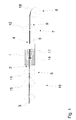
Weitere Vorteile der Erfindung sind in den nachfolgenden Ausführungsbeispielen beschrieben. Es zeigen:
-
Figur 1 - eine Seitenansicht eines Ausschnitts einer erfindungsgemäßen Spinnmaschine während der Garnherstellung, und
-
Figur 2 - eine Seitenansicht eines Ausschnitts einer erfindungsgemäßen Spinnmaschine nach der Unterbrechung der Garnherstellung.
- FIG. 1
- a side view of a section of a spinning machine according to the invention during yarn production, and
- FIG. 2
- a side view of a section of a spinning machine according to the invention after the interruption of the yarn production.
Das Einführen des Fasermaterials 3 in die Spinnstelle 1 erfolgt mit Hilfe einer als Lieferwalzenpaar 11 ausgebildeten Liefereinrichtung 6, die wiederum Teil des Streckwerks 16 sein kann. Innerhalb der Luftwirbelkammer 14 wird schließlich das Fasermaterial 3 bzw. mindestens ein Teil der Fasern des Fasermaterials 3 zur Herstellung des gewünschten Garns 5 mit einer Drehung versehen. Die Drehung entsteht hierbei durch eine gezielte Luftströmung im Bereich einer Spindel 17, wobei die Luftströmung durch nicht gezeigte, tangential in die Luftwirbelkammer 14 mündende Düsen erzeugt wird.The
Ferner umfasst die gezeigte Spinnmaschine eine durch ein Abzugswalzenpaar 12 gebildete Abzugseinrichtung 7 sowie eine dem Abzugswalzenpaar 12 nachgeschaltete Spulvorrichtung 8 für das durch den Ausgang 4 aus der Spinnstelle 1 abgezogene Garn 5.Furthermore, the spinning machine shown comprises a take-
Schließlich ist die Spinnmaschine mit einer Garnüberwachungseinheit 9 ausgerüstet, welche vorher definierte Parameter des Garns 5 (z. B. die Garndicke, die Garnfestigkeit oder andere für die Qualität des Garns 5 repräsentative Parameter) überwacht. Die Garnüberwachungseinheit 9 arbeitet dabei vorzugsweise berührungslos.Finally, the spinning machine is equipped with a
Die erfindungsgemäße Vorrichtung muss nicht zwangsweise ein Streckwerk 16 aufweisen, wie dies in
Das erfindungsgemäße Verfahren zur Unterbrechung der Garnherstellung ist nun aus der Zusammenschau der
Wird nun mit Hilfe der Garnüberwachungseinheit 9 (die auch an anderer Stelle positioniert sein kann) eine definierte Abweichung des oder der überwachten Garnparameter von entsprechenden Sollwerten detektiert oder steht ein Spulenwechsel an, so werden die Fördergeschwindigkeiten der Liefereinrichtung 6, der Abzugseinrichtung 7 und der Spulvorrichtung 8 allmählich reduziert. Ebenso kann die Reduzierung erfolgen, bevor die Spinnmaschine abgeschaltet wird.If, with the aid of the yarn monitoring unit 9 (which can also be positioned elsewhere), a defined deviation of the monitored yarn parameter from corresponding nominal values is detected or a bobbin change occurs, the conveying speeds of the
Die Reduzierung muss hierbei nicht gleichzeitig oder kontinuierlich erfolgen. In jedem Fall sollten die jeweiligen Fördergeschwindigkeiten jedoch derart gedrosselt werden, dass der Spinnprozess so lange wie möglich aufrechterhalten werden kann. Ein Reißen des Garns 5, wie im Stand der Technik üblich, kann auf diese Weise ausgeschlossen werden. Vielmehr ist es Ziel der Reduzierung der Fördergeschwindigkeiten, dass der stabile Spinnprozess durch Unterschreiten definierter Fördergeschwindigkeiten zusammenbricht und somit ab einem gewissen Zeitpunkt kein Garn 5 mehr aus dem Fasermaterial 3 erzeugt wird. Zu diesem Zeitpunkt kommt es schließlich zur gewünschten Unterbrechung der Garnherstellung, bei der sich das Garn 5 ohne separate Krafteinwirkung von dem Fasermaterial 3 löst. Dies kann beispielsweise dadurch erreicht werden, dass die Fördergeschwindigkeit der Liefereinrichtung 6 so weit reduziert wird, dass sie keine ausreichende Menge an Fasermaterial 3 mehr liefert, um hieraus ein Garn 5 zu bilden. Auch ist es möglich, die Fördergeschwindigkeit des Abzugswalzenpaars 12 langsamer (oder bei Bedarf auch schneller) zu drosseln als die Fördergeschwindigkeit des Lieferwalzenpaars 11 und/oder der Spulvorrichtung 8.The reduction need not be simultaneous or continuous. In any case, however, the respective conveying speeds should be throttled so that the spinning process can be maintained as long as possible. Tearing of the
Nachdem die Garnherstellung abgebrochen wurde, ist es schließlich möglich, das Abzugswalzenpaar 12 einen geringen Zeitraum weiter zu betreiben, so dass das entstandene Ende 10 des Garns 5 nach dem endgültigen Stillstand der Liefereinrichtung 6, der Abzugseinrichtung 7 und der Spulvorrichtung 8 eine Position einnimmt, wie sie in
Im Ergebnis befindet sich das für den Anspinnvorgang nötige Ende 10 des Garns 5 nun an einer definierten Stelle innerhalb der Spinnstelle 1, so dass der Anspinnvorgang gestartet werden kann, ohne dass zuvor das Ende 10 des Garns 5, z. B. auf der Oberfläche einer Spule 18 der Spulvorrichtung 8, gesucht werden müsste (wie dies im Stand der Technik üblich ist).As a result, the necessary for the piecing process end 10 of the
Für den Anspinnvorgang wird das Ende 10 des Garns 5 schließlich mit Hilfe eines Serviceroboters, einer spinnstelleneigenen Garnhandhabungseinrichtung oder auch manuell entgegen der eigentlichen Spinnrichtung in die Luftwirbelkammer 14, zwischen den Eingang 2 der Spinnstelle 1 und der Liefereinrichtung 6 oder zwischen die Liefereinrichtung 6 und einem angrenzenden Walzenpaar 15 des Streckwerks 16 verschoben. Dort kann es mit dem Fasermaterial 3 in Kontakt gebracht und wieder in die Spinnstelle 1 eingeführt werden. Der Spinnvorgang beginnt schließlich von neuem.For the piecing process, the
Im Übrigen ist die Erfindung nicht auf die dargestellten Ausführungsbeispiele beschränkt. Vielmehr sind sämtliche Kombinationen der beschriebenen Einzelmerkmale, wie sie in den Ansprüchen, der Beschreibung sowie den Figuren gezeigt oder beschrieben sind und soweit eine entsprechende Kombination technisch möglich bzw. sinnvoll erscheint, Gegenstand der Erfindung.Incidentally, the invention is not limited to the illustrated embodiments. Rather, all combinations of the individual features described, as shown or described in the claims, the description and the figures and as far as a corresponding combination is technically possible or seems reasonable, the subject of the invention.
So kann das Garn 5 nach der Unterbrechung der Garnherstellung, wie auch in den
- 11
- Spinnstellespinning unit
- 22
- Eingangentrance
- 33
- Fasermaterialfiber material
- 44
- Ausgangoutput
- 55
- Garnyarn
- 66
- LiefereinrichtungSupply means
- 77
- Abzugseinrichtungoff device
- 88th
- Spulvorrichtungspooling device
- 99
- GarnüberwachungseinheitGarnüberwachungseinheit
- 1010
- Ende des hergestellten GarnsEnd of the manufactured yarn
- 1111
- LieferwalzenpaarPair of delivery rollers
- 1212
- AbzugswalzenpaarOff rollers
- 1313
- Garnspeicheryarn store
- 1414
- LuftwirbelkammerAir swirl chamber
- 1515
- Walzenpaar eines StreckwerksRoller pair of a drafting system
- 1616
- Streckwerkdrafting system
- 1717
- Spindelspindle
- 1818
- SpuleKitchen sink
- 1919
- Schneid- und/oder EntsorgungseinrichtungCutting and / or disposal facility
Claims (15)
Applications Claiming Priority (1)
| Application Number | Priority Date | Filing Date | Title |
|---|---|---|---|
| DE102011053812A DE102011053812A1 (en) | 2011-09-21 | 2011-09-21 | Spinning machine and method for interrupting the production of yarn on a spinning machine |
Publications (3)
| Publication Number | Publication Date |
|---|---|
| EP2573238A2 true EP2573238A2 (en) | 2013-03-27 |
| EP2573238A3 EP2573238A3 (en) | 2015-03-25 |
| EP2573238B1 EP2573238B1 (en) | 2016-07-06 |
Family
ID=46963505
Family Applications (1)
| Application Number | Title | Priority Date | Filing Date |
|---|---|---|---|
| EP12184769.3A Active EP2573238B1 (en) | 2011-09-21 | 2012-09-18 | Spinning machine and method for interrupting the production of thread on a spinning machine |
Country Status (6)
| Country | Link |
|---|---|
| US (1) | US8919091B2 (en) |
| EP (1) | EP2573238B1 (en) |
| JP (1) | JP6094790B2 (en) |
| CN (1) | CN103014946B (en) |
| BR (1) | BR102012023913A2 (en) |
| DE (1) | DE102011053812A1 (en) |
Cited By (1)
| Publication number | Priority date | Publication date | Assignee | Title |
|---|---|---|---|---|
| EP2955255A3 (en) * | 2014-06-12 | 2016-05-18 | Maschinenfabrik Rieter Ag | Air spinning machine and method for operating an air spinning machine |
Families Citing this family (10)
| Publication number | Priority date | Publication date | Assignee | Title |
|---|---|---|---|---|
| DE102012108380A1 (en) * | 2012-06-19 | 2013-12-19 | Maschinenfabrik Rieter Ag | Air-jet spinning machine and method of operating the same |
| DE102014103193A1 (en) | 2014-03-11 | 2015-09-17 | Rieter Ingolstadt Gmbh | Spinning machine and method for transferring a yarn to a piecing device |
| CH709953A1 (en) * | 2014-07-30 | 2016-02-15 | Rieter Ag Maschf | Method for operating an air spinning machine. |
| DE102015108706A1 (en) * | 2015-06-02 | 2016-12-08 | Maschinenfabrik Rieter Ag | Spinning a Luftspinnmaschine and method for operating the same |
| DE102015110486A1 (en) * | 2015-06-30 | 2017-01-05 | Rieter Ingolstadt Gmbh | Spinning station of a spinning machine and method for operating a spinning station |
| DE102015110992A1 (en) * | 2015-07-08 | 2017-01-12 | Rieter Ingolstadt Gmbh | Spinning machine and method for operating a spinning machine with a plurality of spinning stations |
| DE102015117204A1 (en) * | 2015-10-08 | 2017-04-13 | Rieter Ingolstadt Gmbh | Process for preparing a yarn end for piecing on a rotor spinning device of a rotor spinning machine and rotor spinning machine |
| CH712663A1 (en) * | 2016-07-14 | 2018-01-15 | Rieter Ag Maschf | Process for processing a strand-like fiber composite and roving machine. |
| DE102016121331A1 (en) * | 2016-11-08 | 2018-05-09 | Maschinenfabrik Rieter Ag | Spinneret for an air spinning machine and method for operating such |
| CN106637556B (en) * | 2017-02-19 | 2019-02-01 | 广西剑麻集团山圩剑麻制品有限公司 | Spinning machine disconnection self-stopping self-opening device |
Family Cites Families (20)
| Publication number | Priority date | Publication date | Assignee | Title |
|---|---|---|---|---|
| CH436057A (en) * | 1965-08-05 | 1967-05-15 | Vyzk Ustav Bavlnarsky | Method for eliminating thread breakage on a spinning machine with a rotating spinning chamber and spinning machine for carrying out this method |
| CH451765A (en) | 1966-04-26 | 1968-05-15 | Schubert & Salzer Maschinen | Method and device for stopping and restarting a sliver spinning device |
| DE2313788A1 (en) | 1973-03-20 | 1974-10-03 | Krupp Gmbh | PROCEDURE FOR INDEPENDENT START-UP AND STOP OF AN OPEN-END SPINNING MACHINE |
| DE2849061C2 (en) | 1977-11-17 | 1986-09-25 | Hollingsworth (U.K.) Ltd., Accrington, Lancashire | Method for stopping an OE rotor spinning machine and an OE rotor spinning machine |
| DE3205535A1 (en) * | 1982-02-17 | 1983-09-08 | Schubert & Salzer Maschinenfabrik Ag, 8070 Ingolstadt | METHOD AND DEVICE FOR STOPPING AND RESTARTING AN OPEN-END SPINNING MACHINE WITH A VARIETY OF SPINNING DEVICES |
| DE3401316A1 (en) * | 1984-01-17 | 1985-07-18 | Fritz 7347 Bad Überkingen Stahlecker | METHOD FOR STOPPING AND RESTARTING AN OE-FRICTION SPINNING UNIT |
| WO1987003310A1 (en) * | 1985-11-21 | 1987-06-04 | Schubert & Salzer Maschinenfabrik Aktiengesellscha | Process and device for rethreading a spinning device provided with a pneumatic twisting element |
| DE3635510C2 (en) | 1986-10-18 | 1995-10-26 | Schlafhorst & Co W | Method and device for decommissioning and subsequent recommissioning of an OE rotor spinning machine |
| US5163279A (en) * | 1988-02-20 | 1992-11-17 | Hans Stahlecker | Arrangement for producing feeding packages for a twisting operation |
| DE3817493A1 (en) * | 1988-05-21 | 1989-11-30 | Fritz Stahlecker | SPINNING MACHINE WITH A VARIETY OF SPINNING DEVICES TO GENERATE AS REPLACEMENT SPOOLS FOR A TWISTING REEL |
| DE3902548A1 (en) * | 1989-01-28 | 1990-08-02 | Fritz Stahlecker | Apparatus for producing bobbins serving as feed bobbins for twisting |
| IT1255208B (en) * | 1991-07-25 | 1995-10-20 | Harald Dallmann | PROCEDURE AND DEVICE FOR INTERMEDIATE STORAGE OF THREADS TO START THE SPINNING AGAIN |
| DE4231958A1 (en) * | 1992-09-24 | 1994-03-31 | Schlafhorst & Co W | Automatic yarn winder - has single arm arrangement to place both yarn ends in splicer. |
| JPH07126933A (en) * | 1993-10-29 | 1995-05-16 | Murata Mach Ltd | Spindle unit sifter |
| JP2921479B2 (en) * | 1996-01-30 | 1999-07-19 | 村田機械株式会社 | Spinning machine piecing method |
| EP1219737B2 (en) | 2000-12-22 | 2012-01-18 | Maschinenfabrik Rieter Ag | Procedure for piecing up or joining a yarn created in a spinning station, said spinning station being equiped to carry out the procedure |
| DE10353317B4 (en) * | 2003-11-10 | 2013-06-27 | Wilhelm Stahlecker Gmbh | Method and device for restoring a previously interrupted spinning process |
| JP4120635B2 (en) * | 2004-11-19 | 2008-07-16 | 村田機械株式会社 | Textile machinery |
| DE102007009074A1 (en) * | 2007-02-24 | 2008-08-28 | Oerlikon Textile Gmbh & Co. Kg | spinning device |
| DE102011053811A1 (en) * | 2011-09-21 | 2013-03-21 | Rieter Ingolstadt Gmbh | Spinning machine and method for interrupting the production of yarn on a spinning machine |
-
2011
- 2011-09-21 DE DE102011053812A patent/DE102011053812A1/en not_active Withdrawn
-
2012
- 2012-09-14 US US13/616,791 patent/US8919091B2/en active Active
- 2012-09-18 EP EP12184769.3A patent/EP2573238B1/en active Active
- 2012-09-21 CN CN201210376635.2A patent/CN103014946B/en active Active
- 2012-09-21 JP JP2012208201A patent/JP6094790B2/en active Active
- 2012-09-21 BR BR102012023913-2A patent/BR102012023913A2/en not_active Application Discontinuation
Non-Patent Citations (1)
| Title |
|---|
| None |
Cited By (2)
| Publication number | Priority date | Publication date | Assignee | Title |
|---|---|---|---|---|
| EP2955255A3 (en) * | 2014-06-12 | 2016-05-18 | Maschinenfabrik Rieter Ag | Air spinning machine and method for operating an air spinning machine |
| US9670601B2 (en) | 2014-06-12 | 2017-06-06 | Maschinenfabrik Rieter Ag | Air jet spinning machine and method for operating the same |
Also Published As
| Publication number | Publication date |
|---|---|
| EP2573238B1 (en) | 2016-07-06 |
| US8919091B2 (en) | 2014-12-30 |
| JP6094790B2 (en) | 2017-03-15 |
| US20130067880A1 (en) | 2013-03-21 |
| JP2013067936A (en) | 2013-04-18 |
| BR102012023913A2 (en) | 2014-12-02 |
| EP2573238A3 (en) | 2015-03-25 |
| CN103014946B (en) | 2017-06-23 |
| CN103014946A (en) | 2013-04-03 |
| DE102011053812A1 (en) | 2013-03-21 |
Similar Documents
| Publication | Publication Date | Title |
|---|---|---|
| EP2573237B1 (en) | Spinning machine and method for interrupting the production of thread on a spinning machine | |
| EP2573238B1 (en) | Spinning machine and method for interrupting the production of thread on a spinning machine | |
| EP2679711B1 (en) | Piecing method and device in an air jet spinning machine | |
| EP2573228B2 (en) | Spinning machine and method for discharging an end section of a thread on a spinning machine before a subsequent spinning procedure | |
| EP2784193B1 (en) | Spinning unit of a spinning machine and method for operating the same | |
| EP2918534B1 (en) | Spinning machine and method for transferring a yarn to a piecing device | |
| EP3148913B1 (en) | Method for operating a textile machine, and textile machine for producing rovings | |
| DE102012102695A1 (en) | Roving machine with an arrangement for the detection and removal of yarn defects | |
| EP3153612A1 (en) | Method for preparing a yarn end for spinning on to a rotor spinning device of a rotor spinning machine and rotor spinning machine | |
| DE102013111647A1 (en) | Spinning machine and method for operating the same in case of failure of an external power supply | |
| EP3140440B1 (en) | Textile machine and method for operating same | |
| DE102016119237A1 (en) | Air spinning machine | |
| EP3511275B1 (en) | Textile machine and method for automatically piecing a thread at a working unit of a textile machine | |
| DE102015108706A1 (en) | Spinning a Luftspinnmaschine and method for operating the same | |
| EP3112507B1 (en) | Spinning station of a spinning machine, spinning machine and method for operating a spinning station | |
| WO2021213850A1 (en) | Method for separating a sliver delivered out of a sliver can at a spinning station of a spinning machine, and spinning machine | |
| DE102005031279A1 (en) | Mobile suction device for picking up and transporting yarns, comprising tube into which yarns are sucked via opening provided with yarn separator to reduce twisting of the yarns | |
| EP3140233B1 (en) | Textile machine for producing a roving and method of starting roving production with such a textile machine | |
| EP3149229B1 (en) | Spinning preparation machine | |
| EP4050138B1 (en) | Method of operating a spinning machine work station and work station | |
| EP4051832B1 (en) | Open-end spinning machine, driving process thereof and control unit | |
| WO2018011655A1 (en) | Method for processing a strand-shaped fiber sliver, and roving frame machine | |
| DE4032116A1 (en) | Pneumatic false twist spinner - winds yarn on an intermediate bobbin without repairing yarn breaks which are spliced at a winding station |
Legal Events
| Date | Code | Title | Description |
|---|---|---|---|
| PUAI | Public reference made under article 153(3) epc to a published international application that has entered the european phase |
Free format text: ORIGINAL CODE: 0009012 |
|
| AK | Designated contracting states |
Kind code of ref document: A2 Designated state(s): AL AT BE BG CH CY CZ DE DK EE ES FI FR GB GR HR HU IE IS IT LI LT LU LV MC MK MT NL NO PL PT RO RS SE SI SK SM TR |
|
| AX | Request for extension of the european patent |
Extension state: BA ME |
|
| PUAL | Search report despatched |
Free format text: ORIGINAL CODE: 0009013 |
|
| AK | Designated contracting states |
Kind code of ref document: A3 Designated state(s): AL AT BE BG CH CY CZ DE DK EE ES FI FR GB GR HR HU IE IS IT LI LT LU LV MC MK MT NL NO PL PT RO RS SE SI SK SM TR |
|
| AX | Request for extension of the european patent |
Extension state: BA ME |
|
| RIC1 | Information provided on ipc code assigned before grant |
Ipc: D01H 1/115 20060101ALI20150216BHEP Ipc: D01H 13/14 20060101AFI20150216BHEP |
|
| 17P | Request for examination filed |
Effective date: 20150922 |
|
| RBV | Designated contracting states (corrected) |
Designated state(s): AL AT BE BG CH CY CZ DE DK EE ES FI FR GB GR HR HU IE IS IT LI LT LU LV MC MK MT NL NO PL PT RO RS SE SI SK SM TR |
|
| GRAP | Despatch of communication of intention to grant a patent |
Free format text: ORIGINAL CODE: EPIDOSNIGR1 |
|
| RIC1 | Information provided on ipc code assigned before grant |
Ipc: D01H 1/115 20060101ALI20160211BHEP Ipc: D01H 13/14 20060101AFI20160211BHEP |
|
| INTG | Intention to grant announced |
Effective date: 20160224 |
|
| GRAS | Grant fee paid |
Free format text: ORIGINAL CODE: EPIDOSNIGR3 |
|
| GRAA | (expected) grant |
Free format text: ORIGINAL CODE: 0009210 |
|
| AK | Designated contracting states |
Kind code of ref document: B1 Designated state(s): AL AT BE BG CH CY CZ DE DK EE ES FI FR GB GR HR HU IE IS IT LI LT LU LV MC MK MT NL NO PL PT RO RS SE SI SK SM TR |
|
| REG | Reference to a national code |
Ref country code: GB Ref legal event code: FG4D Free format text: NOT ENGLISH |
|
| REG | Reference to a national code |
Ref country code: AT Ref legal event code: REF Ref document number: 810780 Country of ref document: AT Kind code of ref document: T Effective date: 20160715 Ref country code: CH Ref legal event code: EP |
|
| REG | Reference to a national code |
Ref country code: IE Ref legal event code: FG4D Free format text: LANGUAGE OF EP DOCUMENT: GERMAN |
|
| REG | Reference to a national code |
Ref country code: DE Ref legal event code: R096 Ref document number: 502012007561 Country of ref document: DE |
|
| REG | Reference to a national code |
Ref country code: NL Ref legal event code: MP Effective date: 20160706 |
|
| REG | Reference to a national code |
Ref country code: LT Ref legal event code: MG4D |
|
| PG25 | Lapsed in a contracting state [announced via postgrant information from national office to epo] |
Ref country code: IS Free format text: LAPSE BECAUSE OF FAILURE TO SUBMIT A TRANSLATION OF THE DESCRIPTION OR TO PAY THE FEE WITHIN THE PRESCRIBED TIME-LIMIT Effective date: 20161106 Ref country code: RS Free format text: LAPSE BECAUSE OF FAILURE TO SUBMIT A TRANSLATION OF THE DESCRIPTION OR TO PAY THE FEE WITHIN THE PRESCRIBED TIME-LIMIT Effective date: 20160706 Ref country code: NL Free format text: LAPSE BECAUSE OF FAILURE TO SUBMIT A TRANSLATION OF THE DESCRIPTION OR TO PAY THE FEE WITHIN THE PRESCRIBED TIME-LIMIT Effective date: 20160706 Ref country code: NO Free format text: LAPSE BECAUSE OF FAILURE TO SUBMIT A TRANSLATION OF THE DESCRIPTION OR TO PAY THE FEE WITHIN THE PRESCRIBED TIME-LIMIT Effective date: 20161006 Ref country code: HR Free format text: LAPSE BECAUSE OF FAILURE TO SUBMIT A TRANSLATION OF THE DESCRIPTION OR TO PAY THE FEE WITHIN THE PRESCRIBED TIME-LIMIT Effective date: 20160706 Ref country code: LT Free format text: LAPSE BECAUSE OF FAILURE TO SUBMIT A TRANSLATION OF THE DESCRIPTION OR TO PAY THE FEE WITHIN THE PRESCRIBED TIME-LIMIT Effective date: 20160706 Ref country code: FI Free format text: LAPSE BECAUSE OF FAILURE TO SUBMIT A TRANSLATION OF THE DESCRIPTION OR TO PAY THE FEE WITHIN THE PRESCRIBED TIME-LIMIT Effective date: 20160706 Ref country code: IT Free format text: LAPSE BECAUSE OF FAILURE TO SUBMIT A TRANSLATION OF THE DESCRIPTION OR TO PAY THE FEE WITHIN THE PRESCRIBED TIME-LIMIT Effective date: 20160706 |
|
| PG25 | Lapsed in a contracting state [announced via postgrant information from national office to epo] |
Ref country code: BE Free format text: LAPSE BECAUSE OF NON-PAYMENT OF DUE FEES Effective date: 20160930 Ref country code: ES Free format text: LAPSE BECAUSE OF FAILURE TO SUBMIT A TRANSLATION OF THE DESCRIPTION OR TO PAY THE FEE WITHIN THE PRESCRIBED TIME-LIMIT Effective date: 20160706 Ref country code: SE Free format text: LAPSE BECAUSE OF FAILURE TO SUBMIT A TRANSLATION OF THE DESCRIPTION OR TO PAY THE FEE WITHIN THE PRESCRIBED TIME-LIMIT Effective date: 20160706 Ref country code: GR Free format text: LAPSE BECAUSE OF FAILURE TO SUBMIT A TRANSLATION OF THE DESCRIPTION OR TO PAY THE FEE WITHIN THE PRESCRIBED TIME-LIMIT Effective date: 20161007 Ref country code: LV Free format text: LAPSE BECAUSE OF FAILURE TO SUBMIT A TRANSLATION OF THE DESCRIPTION OR TO PAY THE FEE WITHIN THE PRESCRIBED TIME-LIMIT Effective date: 20160706 Ref country code: PT Free format text: LAPSE BECAUSE OF FAILURE TO SUBMIT A TRANSLATION OF THE DESCRIPTION OR TO PAY THE FEE WITHIN THE PRESCRIBED TIME-LIMIT Effective date: 20161107 Ref country code: PL Free format text: LAPSE BECAUSE OF FAILURE TO SUBMIT A TRANSLATION OF THE DESCRIPTION OR TO PAY THE FEE WITHIN THE PRESCRIBED TIME-LIMIT Effective date: 20160706 |
|
| REG | Reference to a national code |
Ref country code: DE Ref legal event code: R026 Ref document number: 502012007561 Country of ref document: DE |
|
| PLBI | Opposition filed |
Free format text: ORIGINAL CODE: 0009260 |
|
| PG25 | Lapsed in a contracting state [announced via postgrant information from national office to epo] |
Ref country code: RO Free format text: LAPSE BECAUSE OF FAILURE TO SUBMIT A TRANSLATION OF THE DESCRIPTION OR TO PAY THE FEE WITHIN THE PRESCRIBED TIME-LIMIT Effective date: 20160706 Ref country code: MC Free format text: LAPSE BECAUSE OF FAILURE TO SUBMIT A TRANSLATION OF THE DESCRIPTION OR TO PAY THE FEE WITHIN THE PRESCRIBED TIME-LIMIT Effective date: 20160706 Ref country code: EE Free format text: LAPSE BECAUSE OF FAILURE TO SUBMIT A TRANSLATION OF THE DESCRIPTION OR TO PAY THE FEE WITHIN THE PRESCRIBED TIME-LIMIT Effective date: 20160706 |
|
| REG | Reference to a national code |
Ref country code: CH Ref legal event code: PL |
|
| PLAX | Notice of opposition and request to file observation + time limit sent |
Free format text: ORIGINAL CODE: EPIDOSNOBS2 |
|
| 26 | Opposition filed |
Opponent name: SAURER GERMANY GMBH & CO. KG Effective date: 20170406 |
|
| PG25 | Lapsed in a contracting state [announced via postgrant information from national office to epo] |
Ref country code: DK Free format text: LAPSE BECAUSE OF FAILURE TO SUBMIT A TRANSLATION OF THE DESCRIPTION OR TO PAY THE FEE WITHIN THE PRESCRIBED TIME-LIMIT Effective date: 20160706 Ref country code: SM Free format text: LAPSE BECAUSE OF FAILURE TO SUBMIT A TRANSLATION OF THE DESCRIPTION OR TO PAY THE FEE WITHIN THE PRESCRIBED TIME-LIMIT Effective date: 20160706 Ref country code: CZ Free format text: LAPSE BECAUSE OF FAILURE TO SUBMIT A TRANSLATION OF THE DESCRIPTION OR TO PAY THE FEE WITHIN THE PRESCRIBED TIME-LIMIT Effective date: 20160706 Ref country code: SK Free format text: LAPSE BECAUSE OF FAILURE TO SUBMIT A TRANSLATION OF THE DESCRIPTION OR TO PAY THE FEE WITHIN THE PRESCRIBED TIME-LIMIT Effective date: 20160706 Ref country code: BG Free format text: LAPSE BECAUSE OF FAILURE TO SUBMIT A TRANSLATION OF THE DESCRIPTION OR TO PAY THE FEE WITHIN THE PRESCRIBED TIME-LIMIT Effective date: 20161006 |
|
| GBPC | Gb: european patent ceased through non-payment of renewal fee |
Effective date: 20161006 |
|
| REG | Reference to a national code |
Ref country code: IE Ref legal event code: MM4A |
|
| REG | Reference to a national code |
Ref country code: FR Ref legal event code: ST Effective date: 20170531 |
|
| PG25 | Lapsed in a contracting state [announced via postgrant information from national office to epo] |
Ref country code: IE Free format text: LAPSE BECAUSE OF NON-PAYMENT OF DUE FEES Effective date: 20160918 Ref country code: CH Free format text: LAPSE BECAUSE OF NON-PAYMENT OF DUE FEES Effective date: 20160930 Ref country code: GB Free format text: LAPSE BECAUSE OF NON-PAYMENT OF DUE FEES Effective date: 20161006 Ref country code: LI Free format text: LAPSE BECAUSE OF NON-PAYMENT OF DUE FEES Effective date: 20160930 Ref country code: FR Free format text: LAPSE BECAUSE OF NON-PAYMENT OF DUE FEES Effective date: 20160930 |
|
| PG25 | Lapsed in a contracting state [announced via postgrant information from national office to epo] |
Ref country code: LU Free format text: LAPSE BECAUSE OF NON-PAYMENT OF DUE FEES Effective date: 20160918 Ref country code: SI Free format text: LAPSE BECAUSE OF FAILURE TO SUBMIT A TRANSLATION OF THE DESCRIPTION OR TO PAY THE FEE WITHIN THE PRESCRIBED TIME-LIMIT Effective date: 20160706 |
|
| PLBB | Reply of patent proprietor to notice(s) of opposition received |
Free format text: ORIGINAL CODE: EPIDOSNOBS3 |
|
| REG | Reference to a national code |
Ref country code: BE Ref legal event code: MM Effective date: 20160930 |
|
| PG25 | Lapsed in a contracting state [announced via postgrant information from national office to epo] |
Ref country code: CY Free format text: LAPSE BECAUSE OF FAILURE TO SUBMIT A TRANSLATION OF THE DESCRIPTION OR TO PAY THE FEE WITHIN THE PRESCRIBED TIME-LIMIT Effective date: 20160706 Ref country code: HU Free format text: LAPSE BECAUSE OF FAILURE TO SUBMIT A TRANSLATION OF THE DESCRIPTION OR TO PAY THE FEE WITHIN THE PRESCRIBED TIME-LIMIT; INVALID AB INITIO Effective date: 20120918 |
|
| PG25 | Lapsed in a contracting state [announced via postgrant information from national office to epo] |
Ref country code: MT Free format text: LAPSE BECAUSE OF FAILURE TO SUBMIT A TRANSLATION OF THE DESCRIPTION OR TO PAY THE FEE WITHIN THE PRESCRIBED TIME-LIMIT Effective date: 20160706 Ref country code: MK Free format text: LAPSE BECAUSE OF FAILURE TO SUBMIT A TRANSLATION OF THE DESCRIPTION OR TO PAY THE FEE WITHIN THE PRESCRIBED TIME-LIMIT Effective date: 20160706 |
|
| PLAB | Opposition data, opponent's data or that of the opponent's representative modified |
Free format text: ORIGINAL CODE: 0009299OPPO |
|
| PG25 | Lapsed in a contracting state [announced via postgrant information from national office to epo] |
Ref country code: AL Free format text: LAPSE BECAUSE OF FAILURE TO SUBMIT A TRANSLATION OF THE DESCRIPTION OR TO PAY THE FEE WITHIN THE PRESCRIBED TIME-LIMIT Effective date: 20160706 |
|
| R26 | Opposition filed (corrected) |
Opponent name: SAURER SPINNING SOLUTIONS GMBH & CO. KG Effective date: 20170406 |
|
| REG | Reference to a national code |
Ref country code: AT Ref legal event code: MM01 Ref document number: 810780 Country of ref document: AT Kind code of ref document: T Effective date: 20170918 |
|
| PG25 | Lapsed in a contracting state [announced via postgrant information from national office to epo] |
Ref country code: AT Free format text: LAPSE BECAUSE OF NON-PAYMENT OF DUE FEES Effective date: 20170918 |
|
| REG | Reference to a national code |
Ref country code: DE Ref legal event code: R100 Ref document number: 502012007561 Country of ref document: DE |
|
| PLCK | Communication despatched that opposition was rejected |
Free format text: ORIGINAL CODE: EPIDOSNREJ1 |
|
| PLBN | Opposition rejected |
Free format text: ORIGINAL CODE: 0009273 |
|
| STAA | Information on the status of an ep patent application or granted ep patent |
Free format text: STATUS: OPPOSITION REJECTED |
|
| 27O | Opposition rejected |
Effective date: 20190925 |
|
| P01 | Opt-out of the competence of the unified patent court (upc) registered |
Effective date: 20230329 |
|
| PGFP | Annual fee paid to national office [announced via postgrant information from national office to epo] |
Ref country code: TR Payment date: 20230914 Year of fee payment: 12 |
|
| PGFP | Annual fee paid to national office [announced via postgrant information from national office to epo] |
Ref country code: DE Payment date: 20230928 Year of fee payment: 12 |