EP2572936B1 - Trim part for automobile with integrated lighting device and process for manufacturing it - Google Patents
Trim part for automobile with integrated lighting device and process for manufacturing it Download PDFInfo
- Publication number
- EP2572936B1 EP2572936B1 EP11382302.5A EP11382302A EP2572936B1 EP 2572936 B1 EP2572936 B1 EP 2572936B1 EP 11382302 A EP11382302 A EP 11382302A EP 2572936 B1 EP2572936 B1 EP 2572936B1
- Authority
- EP
- European Patent Office
- Prior art keywords
- lighting
- face
- decorative lining
- areas
- light
- Prior art date
- Legal status (The legal status is an assumption and is not a legal conclusion. Google has not performed a legal analysis and makes no representation as to the accuracy of the status listed.)
- Active
Links
- 238000000034 method Methods 0.000 title claims description 14
- 230000008569 process Effects 0.000 title claims description 14
- 238000004519 manufacturing process Methods 0.000 title description 12
- 239000000758 substrate Substances 0.000 claims description 92
- 239000010410 layer Substances 0.000 claims description 81
- 244000144992 flock Species 0.000 claims description 52
- 239000012790 adhesive layer Substances 0.000 claims description 31
- 238000013532 laser treatment Methods 0.000 claims description 29
- 230000005611 electricity Effects 0.000 claims description 25
- 239000000463 material Substances 0.000 claims description 20
- 239000000853 adhesive Substances 0.000 claims description 18
- 230000001070 adhesive effect Effects 0.000 claims description 18
- 238000005520 cutting process Methods 0.000 claims description 9
- 238000005304 joining Methods 0.000 claims description 7
- 229920003229 poly(methyl methacrylate) Polymers 0.000 claims description 4
- 239000004926 polymethyl methacrylate Substances 0.000 claims description 4
- 238000003825 pressing Methods 0.000 claims description 3
- 239000004417 polycarbonate Substances 0.000 claims description 2
- 229920000515 polycarbonate Polymers 0.000 claims description 2
- 230000006870 function Effects 0.000 description 14
- 230000000694 effects Effects 0.000 description 13
- 238000005286 illumination Methods 0.000 description 10
- 230000010354 integration Effects 0.000 description 7
- 230000000712 assembly Effects 0.000 description 4
- 238000000429 assembly Methods 0.000 description 4
- 238000005516 engineering process Methods 0.000 description 4
- 239000007921 spray Substances 0.000 description 3
- 239000002390 adhesive tape Substances 0.000 description 2
- 239000003086 colorant Substances 0.000 description 2
- 239000004033 plastic Substances 0.000 description 2
- 229920003023 plastic Polymers 0.000 description 2
- 230000001681 protective effect Effects 0.000 description 2
- 230000009471 action Effects 0.000 description 1
- 230000006978 adaptation Effects 0.000 description 1
- 230000005540 biological transmission Effects 0.000 description 1
- 230000015572 biosynthetic process Effects 0.000 description 1
- 230000008859 change Effects 0.000 description 1
- 238000005034 decoration Methods 0.000 description 1
- 230000002349 favourable effect Effects 0.000 description 1
- 230000006872 improvement Effects 0.000 description 1
- 238000010348 incorporation Methods 0.000 description 1
- 239000002184 metal Substances 0.000 description 1
- 239000004745 nonwoven fabric Substances 0.000 description 1
- 230000002093 peripheral effect Effects 0.000 description 1
- 230000000644 propagated effect Effects 0.000 description 1
- 230000000284 resting effect Effects 0.000 description 1
- 238000009827 uniform distribution Methods 0.000 description 1
- 230000000007 visual effect Effects 0.000 description 1
Images


Classifications
-
- B—PERFORMING OPERATIONS; TRANSPORTING
- B60—VEHICLES IN GENERAL
- B60Q—ARRANGEMENT OF SIGNALLING OR LIGHTING DEVICES, THE MOUNTING OR SUPPORTING THEREOF OR CIRCUITS THEREFOR, FOR VEHICLES IN GENERAL
- B60Q3/00—Arrangement of lighting devices for vehicle interiors; Lighting devices specially adapted for vehicle interiors
- B60Q3/50—Mounting arrangements
- B60Q3/54—Lighting devices embedded in interior trim, e.g. in roof liners
-
- B—PERFORMING OPERATIONS; TRANSPORTING
- B60—VEHICLES IN GENERAL
- B60Q—ARRANGEMENT OF SIGNALLING OR LIGHTING DEVICES, THE MOUNTING OR SUPPORTING THEREOF OR CIRCUITS THEREFOR, FOR VEHICLES IN GENERAL
- B60Q3/00—Arrangement of lighting devices for vehicle interiors; Lighting devices specially adapted for vehicle interiors
- B60Q3/60—Arrangement of lighting devices for vehicle interiors; Lighting devices specially adapted for vehicle interiors characterised by optical aspects
- B60Q3/62—Arrangement of lighting devices for vehicle interiors; Lighting devices specially adapted for vehicle interiors characterised by optical aspects using light guides
- B60Q3/64—Arrangement of lighting devices for vehicle interiors; Lighting devices specially adapted for vehicle interiors characterised by optical aspects using light guides for a single lighting device
-
- B—PERFORMING OPERATIONS; TRANSPORTING
- B60—VEHICLES IN GENERAL
- B60Q—ARRANGEMENT OF SIGNALLING OR LIGHTING DEVICES, THE MOUNTING OR SUPPORTING THEREOF OR CIRCUITS THEREFOR, FOR VEHICLES IN GENERAL
- B60Q3/00—Arrangement of lighting devices for vehicle interiors; Lighting devices specially adapted for vehicle interiors
- B60Q3/70—Arrangement of lighting devices for vehicle interiors; Lighting devices specially adapted for vehicle interiors characterised by the purpose
- B60Q3/74—Arrangement of lighting devices for vehicle interiors; Lighting devices specially adapted for vehicle interiors characterised by the purpose for overall compartment lighting; for overall compartment lighting in combination with specific lighting, e.g. room lamps with reading lamps
-
- B—PERFORMING OPERATIONS; TRANSPORTING
- B60—VEHICLES IN GENERAL
- B60R—VEHICLES, VEHICLE FITTINGS, OR VEHICLE PARTS, NOT OTHERWISE PROVIDED FOR
- B60R13/00—Elements for body-finishing, identifying, or decorating; Arrangements or adaptations for advertising purposes
- B60R13/02—Internal Trim mouldings ; Internal Ledges; Wall liners for passenger compartments; Roof liners
- B60R13/0212—Roof or head liners
- B60R13/0225—Roof or head liners self supporting head liners
-
- B—PERFORMING OPERATIONS; TRANSPORTING
- B60—VEHICLES IN GENERAL
- B60R—VEHICLES, VEHICLE FITTINGS, OR VEHICLE PARTS, NOT OTHERWISE PROVIDED FOR
- B60R13/00—Elements for body-finishing, identifying, or decorating; Arrangements or adaptations for advertising purposes
- B60R13/02—Internal Trim mouldings ; Internal Ledges; Wall liners for passenger compartments; Roof liners
- B60R2013/0287—Internal Trim mouldings ; Internal Ledges; Wall liners for passenger compartments; Roof liners integrating other functions or accessories
-
- Y—GENERAL TAGGING OF NEW TECHNOLOGICAL DEVELOPMENTS; GENERAL TAGGING OF CROSS-SECTIONAL TECHNOLOGIES SPANNING OVER SEVERAL SECTIONS OF THE IPC; TECHNICAL SUBJECTS COVERED BY FORMER USPC CROSS-REFERENCE ART COLLECTIONS [XRACs] AND DIGESTS
- Y10—TECHNICAL SUBJECTS COVERED BY FORMER USPC
- Y10T—TECHNICAL SUBJECTS COVERED BY FORMER US CLASSIFICATION
- Y10T29/00—Metal working
- Y10T29/49—Method of mechanical manufacture
- Y10T29/49826—Assembling or joining
Definitions
- the present invention relates to a trim part for an automobile with an integrated lighting device, the function of which is to provide a decorative light inside the vehicle cabin.
- the invention relates to a manufacturing process for this trim part with an integrated lighting device.
- the trim part with integrated lighting device of the invention comprises a compact assembly with a small thickness, easy to handle and assemble, in which is established a control for the light emitted from inside the trim part towards the vehicle cabin by configuring in it localised areas that allow light to emerge in a personalised manner, and a control of the quality of the light emitted through said localised areas that allow the light to emerge.
- a trim part such as for a roof, is a vehicle element normally formed by superposing several layers that are joined to one another and are formed by applying heat and pressure.
- a laminar element with a reduced thickness is obtained that is adapted to the shape of the inside of the vehicle body, specifically to the area of the body in which it is placed and with the function of covering the metal of said body, providing an aesthetic finish among other functions.
- a trim part has a mainly aesthetic purpose, as it is an element that is seen from inside the vehicle cabin.
- a roof trim part can have other functions associated to the various layers that make up its structure, such as structural, insulating or acoustic enhancement functions.
- a trim part can incorporate other elements in addition to those that make up its structure, providing additional functions such as illumination.
- the illumination function can encompass several different types of illumination meant to provide enough light to allow the occupants to distinguish the outline of the objects that are inside the cabin.
- a reading light refers to the illumination function meant to provide enough light so that occupants can read books or documents.
- the illumination function When the purpose of the illumination function is to provide a decorative effect, defining visible illuminated shapes, this is referred to as a decorative light.
- the trim part of the present invention comprises a decorative illumination function, although it optionally can also include any of the other illumination types described above.
- trim parts that comprise the lighting devices for obtaining decorative light in which the lighting elements are not disposed assembled but as an integral part of the trim part, resulting in a compact assembly.
- One of the purposes of these assemblies is to achieve a good integration of the lighting devices in the trim parts that house them, in some cases making them imperceptible when the lighting device that generates the decorative light is not on,
- the lighting devices must also comprise elements with a small thickness, such as for example electro-luminescent sheets or small LED light sources, which can be integrated between the various layers of the part, so that they do not significantly increase the thickness of the assembly.
- Patents EP1418090 , EP2215296 , DE102006012606 These examples are illustrated by Patents EP1418090 , EP2215296 , DE102006012606 .
- the proposed solution is to use a lighting source that is able to illuminate an area as large as the area of the trim part to be illuminated, such as a set of LEDs distributed evenly in said area, or an electro-luminescent panel of the same size as the trim part area to be illuminated.
- the lighting source is placed on a lateral area corresponding to the perimeter of the guide element, resulting in an assembly with dimensions that exceed the perimeter of the trim itself, so that the assembly is not very compact and fragile, and requires protective element for the lighting source to prevent it from being damaged, and additional reflective elements to make full use of the light emitted by said lighting source.
- said protruding arrangement of the lighting sources and the other additional elements implies increasing the space occupied by the assembly, both in its transportation and when it is assembled inside the vehicle.
- Patent DE102006012606 describes solutions of this type.
- the goal is a configuration of the assembly such that it allows controlling the light let out through certain areas of the trim part located appropriately, in order to obtain decorative light according to certain predefined patterns.
- This control of the light outlet is established firstly regarding the versatility or customisation of light exit patterns, so that the decorative lining has localised areas that allow light to exist and areas that stop it, allowing complete freedom of design, and secondly regarding the quality, so that said light exit areas that define the light patterns are configured by perfectly defined contours which also allow diffusing the light in a uniform manner in the light exit areas.
- WO2006057531 discloses a light emitting mat for vehicles which comprises a transparent decoration plate with predetermined decorative patterns through which light pass.
- the predetermined decorative patterns can be made by laser processing.
- decorative patterns are defined in a transparent decorative plate which allows the light passes through said transparent decorative plate except in the areas of it which have been treated for example by laser to modify the trajectory of the light.
- the present invention therefore relates to a trim part for an automobile having an integrated lighting device to provide decorative lighting that comprises a first layer facing the inside of the vehicle cabin, through which the light exits from inside the trim part, and a second part facing the vehicle body, such that said trim part comprises a lighting substrate and a decorative lining according to claim 1.
- the invention relates to a process for obtaining a trim part for an automobile with an integrated lighting device for providing decorative lighting, formed by a first face facing towards the inside of the vehicle cabin and through which the light can exit the inside of the trim, and a second face facing the vehicle body, where said trim comprises a lighting substrate and a decorative lining according to claim 13.
- trim part refers to both a complete trim and to part of one that can be joined to another element to form a complete trim.
- removing at least one part of the decorative lining by a laser treatment refers to applying a laser beam to the decorative lining in order to remove at least one part of the material that forms it, leaving uncovered the lighting guide means and thereby allow the emitted light to exit through it.
- the lighting source or LED is out of the projected area of the areas that allow the light to exit on the guide means, so that the light is not propagated directly from the lighting source but instead indirectly through the guide means.
- the configuration of a light pattern by using a laser beam becomes a simple and versatile operation.
- the execution of the light exit areas by a laser treatment greatly enhances two aspects that directly affect the quality of the light exit through said light exit areas.
- the first of these aspects is associated with the definition of the contours that form the areas of the lining that allow the light to exit, and the other is associated with the uniformity of transmission of the light through said lining areas.
- the laser treatment also results in the removal of the material that forms part of the lining in a clean and precise manner, adjusting it perfectly to the predetermined light pattern that defines the light exit areas.
- the ability to control the uniformity of the material removed from the decorative lining, in addition to allowing an accurate definition of the contours that define the areas that allow the light to exit, also allows a uniform transparency of said areas by the full removal of the excess decorative lining material.
- This uniform transparency together with the use of lighting guide means in combination with the lighting sources, allow the light to be transmitted in a uniform manner.
- the decorative lining is configured by a flocking element formed either by support means, adhesive means and a layer of flock, or by a layer of flock.
- a decorative lining with these characteristics allows acting directly on the control of the light exit through it, and specifically allows improving the opacity of areas that prevent light exit, as said flocked decorative lining acts as an opaque element in itself.
- the trim part with integrated lighting device described provides direct advantages to the user of said product by combining the aspects that act on the quality of the light emitted through the lining areas that allow the light to exit, together with the good appearance of the trim part due to the full integration of the elements that make up the lighting device.
- the trim part of the invention also has direct advantages for its manufacturer, on one hand due to the characteristics of the manufacturing process for the trim part and specifically to the configuration of the light pattern using a laser treatment, which allows creating light exit areas in a versatile, simple manner at a low cost, and on another hand due to the optimisation of the lighting sources due to the use of lighting guide means in combination therewith, in addition to the action on the handling, transport and assembly of the trim part due to the integration of the elements that make up the lighting device.
- the present invention relates to a trim part (1) with an integrated lighting device (4) that comprises a lighting substrate (3), which in turn comprises a base substrate (5) and a lighting device (4), said lighting substrate (3) being covered by a decorative lining (2) in which have been prepared some areas (2.3) that allow light to pass and other areas (2.4) that prevent light from passing, establishing by their combination a lighting patter (11). These areas (2.3) that allow light to pass are created by a laser treatment that removes at least part of the material of said decorative lining (2).
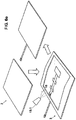
- Figure 1 shows a trim part (1) according to the invention, incorporating an integrated lighting device (4) for providing decorative lighting.
- This trim part (1) has a first face (1.1) that faces towards the vehicle cabin, through which is established the light exit from inside the trim part, and a second face (1.2) that faces the vehicle body, in which is housed the trim part (1), which can be a roof trim, a door trim, a trim for covering a post, etc. or an element coupled to any of the foregoing for configuring a complete trim.
- the trim part (1) of the invention is formed by a set of superimposed elements forming a laminar assembly, and specifically by a lighting substrate (3) that in turn comprises a base substrate (5) and a lighting device (4); and by a decorative lining (2) that completes the configuration of the him part (1) covering the lighting substrate (3) on one of its sides.
- the decorative lining (2) comprises a first face (2.1) facing towards the vehicle cabin and a second face (2,2) facing the vehicle body.
- the decorative lining (2) is the element on which the light pattern (11) is formed by combining the areas (2.3) that allow the light to exit said decorative lining (2), and the areas (2.4) that prevent the light from exiting it, as shown in the AA cross-section shown in figure 2 .
- the configuration of the areas (2.3) that allow the light to exit is obtained by a laser treatment that removes at least one part of the decorative lining (2), leaving uncovered the lighting guide means (4),
- This laser treatment allows personalising the decorative lining (2) by creating a lighting pattern (11) on it in a versatile and simple manner, once that the decorative lining (2) forms part of the trim part (1).
- the use of laser technology to configure the areas (2.3) that allow the light to exit allows firstly a perfect definition of the contours (2.3.1) that define these areas (2.3) and secondly the complete removal of the material that makes up the decorative lining (2) in these areas (2.3), ensuring a uniform distribution of the light,
- the decorative lining (2) is formed by a flocked element that is in turn configured by superposing three elements, some support means (2.10), an adhesive layer (2.100) and a flock layer (2.1000) that forms the last layer of said decorative lining (2).
- both the support means (2.10) and the adhesive layer (2.100) are eliminated, the support means being replaced by the lighting guide means (6) and the adhesive layer (2.100) by the adhesive means (10) for attaching the decorative lining (2) to the lighting substrate (3) described in detail further below.
- the flock layer (2.1000) is joined directly to the first face of said lighting guide means (6) through the adhesive means (10) for attaching the decorative lining (2) to the lighting substrate (3).
- a flocked decorative lining (2) allows acting directly on the control of the exit of the light emitted through it, and specifically allows improving the opacity of the areas (2.4) that prevents the light exit, as this flocked decorative lining (2) acts as an opaque element itself,
- the opacity of the decorative lining (2) is improved without the need to add additional layers under said flocked decorative lining (2), particularly in the areas (2.4) of the lining that prevent the light from exiting.
- the laser treatment operation on the flocked decorative lining (2) allows obtaining other areas (2.5, 2.6, 2.7) in order to obtain different finishes of the flocked decorative lining (2) according to the amount of material removed that forms part of the flocked decorative lining (2).
- the different finishes of the flocked decorative lining (2) are achieved by adjusting the parameters of the laser beam used to execute the laser treatment, such as intensity, progress speed, frequency, etc.
- the areas (3.5) of partial removal of the flock layer in at least one part of the decorative lining (2) are made by removing only one part of the flock layer (2.1000) by a laser treatment of the decorative lining (2), in which optionally the material forming this flock layer (2.1000) is darkened, thereby modifying the appearance of the flock layer (2.1000).
- the areas (2.6) of full removal of the flock layer (2.1000) in least one part of the flocked decorative lining (2) are made by completely removing the flock layer (2.1000) by a laser treatment of the decorative lining (2), exposing the adhesive layer (2.100). In this way, a contrast of colours is obtained in the decorative lining (2), caused by the combination of the colour of the adhesive layer (2.100) and the flock layer (2.1000).
- the final finish of the flocked decorative lining (2) in this specific case, can therefore consist of the combination of the areas (2.3) that allow light to pass and the areas (2.4) that prevent light from passing, with some of the areas (25, 2.6, 2.7) described above.
- This combination would allow obtaining on a trim part (1) a day effect and a completely different night effect.
- the vehicle occupants In the day effect, the vehicle occupants would predominantly perceive the finish produced by the areas (2.4) that prevent light from passing, in combination with the areas (2.5) of partial removal of the flock layer (2.1000), the areas (2.6) of complete removal of the flock layer (2.100) and the areas (2.7) of full removal of the flock layer (2.1000) and adhesive layer (2.100).
- the vehicle occupants will predominantly perceive the finish produced by the areas (2.3) that allow light to exit, and particularly the effect of the light emitted through these in contrast with the areas (2.4) that prevent light from passing.
- the night effect allows the vehicle occupants to appreciate the decorative light pattern (11) formed by the combination of the areas (2.3) that allow light to exit and the areas (2.4) that prevent light from passing when the lighting source (8) is active.
- the lighting substrate (3) which in turn comprises the lighting device (4) and the base substrate (5),
- This lighting substrate (3) shown in Figure 3a under the decorative lining (2) comprises a first layer (3.1) facing the inside of the vehicle cabin and a second face (3.2) facing the vehicle body.
- both the base substrate (5) and the lighting device (4) comprise in turn a first face (5.1, 4. 1) facing the inside of the cabin and a second face (5.2, 4.2) facing the vehicle body.
- the lighting device that forms the lighting substrate (3) is located between the base substrate (5) and the decorative lining (2).
- the union of the lighting device (4) on the base substrate (5) can be achieved by housing it in a cavity (5.3) made in the base substrate (5) for this purpose, as shown in figures 3b , or simply resting on the surface of this base substrate (5), protruding out of its main surface on which the lighting device (4) rests.
- This lighting device (4) as shown in Figures 3b and 3c , in turn comprises:
- At least part of the electricity conducting means (7) are located between the base support (5) and the lighting guide means (6) that form the lighting device (4).
- the lighting guide means (6) are located between the base support (5) and the decorative lining (2).
- These lighting guide means (6) comprise at least one laminar element that copies the shape of the trim part (1), completely adapting to it and thereby favouring the integration of the lighting device (4) in said trim part (1).
- these lighting guide means (6) have at least one orifice (6.3) made in their second face (6.2) in correspondence with said LED (8).
- the number of LEDs (8) can vary according to the surface of the trim part (1) to illuminate, and can comprise one or more LEDs (8) working in collaboration with the lighting guide means (6).
- At least one LED (8) of the lighting device (4) is connected with the electricity conducting means (7) and is at least partially housed in the orifice (6.3) disposed in the lighting guide means (6). Additionally, in a specific case of the invention there can be more than one LED (8) inside a single orifice (6.3) of the lighting guide means (6).
- this light is emitted as light beams (8.1) that enter, through a side wall (6.3.1) of the orifice (6.3), the lighting guide means (6) and are led by and propagate through these until reaching the areas (2.3) that allow the light to exit, as shown in the enlargement of Figure 2 .
- the light beams (8.1) enter in a more favourable manner the lighting guide means (6), facilitating their propagation through them.
- FIG. 2 another peculiarity of the trim part (1) of the invention with an integrated lighting device (4) is that at least one LED (8) is not in direct correspondence with the areas (2,1) that allow the light to exit the decorative lining (2), This LED (8) is out of the projected area of the areas (2.3) that allow the light to exit to the lighting guide means (6).
- an indirect illumination mode is sought in which the light emitted by the trim part (1) and specifically through the areas (2.3) that allow the light to exit, is evenly distributed throughout the lighting guide means (6), reducing its intensity with respect to a light beam emitted directly from the LED (8) in order to obtain a decorative lighting.
- Another of the elements that form the lighting substrate (3) is the base substrate (5).
- This base substrate can be formed by one layer or several superposed layers of different materials, formed by applying heat and applying pressure inside a press (17), depending on the manufacturing technology used to configure the lining (1).
- These technologies can consist of injecting one or several plastic materials inside a mold, cold forming of one or several layers, applying heat on the layer or layers that form the base substrate before introducing it in a press (17), or hot forming in which the heat and pressure are applied simultaneously inside a press.
- the electricity conducting means (7) pass from the first face (5.1) of the base substrate (5), where at least part of the electricity conducting means (7) with the LED (8) are located, to the second face (5.2) of the base substrate (5).
- this base substrate (5) can have an orifice (5.4) for said passage of the electricity conducting means (7) from the first face (5.1) of the base substrate (5) to its second face (5,2)
- This orifice (5.4) can be an existing orifice, such as one corresponding to the position of a lighting console, or an orifice (5.4) provided specifically for this function.
- Figure 5 shows a specific embodiment of the invention in which the trim part (1) with integrated lighting device consists of a roof trim.
- stage a) for obtaining the base substrate (5) represented in figure 6a is performed.
- This stage consists of forming one layer or several superposed layers of different materials by applying heat and by applying pressure in a press (17), depending on the manufacturing technology used to configure the trim part (1).
- This forming operation can consist of injecting one or several plastic materials in a mold, cold forming of one or several layers, applying heat to the layer or layers that make up the base substrate (5) before introducing it in a press (17), or hot forming where the heat and pressure are applied simultaneously in a press (17).
- an light-conducting laminar element is formed to obtain the lighting guide means (6).
- This forming is performed such that the light-conducting de laminar element copies the final shape of the trim part (1) to favour a complete adaptation and integration of said lighting guide means (6) in the trim part (1).
- Said light-conducting laminar element can be made, for example, of polymethylmethacrylate (PMMA) or polycarbonate (PC), which are characterised by their transparency among other factors.
- PMMA polymethylmethacrylate
- PC polycarbonate
- At least one orifice (6.3) is made in the second face (6.2) thereof, which in a specific case can be a through orifice (6.3) as shown in the figures, so that the orifice (6.3) reaches the first face (6.1) that forms the lighting guide means (6), although it can be a non-through orifice.
- This orifice (6.3) will allow housing, at least partially, at least one LED (8) and in a specific case will allow housing more than one LED (8).
- At least one LED (8) is placed in the orifice (6.3) so that it is at least partially housed inside the orifice (6.3).
- the LED or LEDs (8) are placed in the orifice (6.3) of the lighting guide means (6) such that its position is not in direct correspondence with the areas (2.3) that allow the light to exit the decorative lining (2).
- said LED or LEDs (8) have the characteristic of emitting lighting beams (8.1) which, through a side wall (6.3.1) of the orifice (6.3), enter the lighting guide means (6) and are led by and propagate through them until reaching the areas
- the lighting source is connected to the electricity conducting means (7) so that, once the LED or LEDs (8) that make up the lighting device (4) are in place, the electricity conducting means (7) are attached to the second face (6.2) of the lighting guide means (6), for example with adhesive tape (7.2).
- positioning means can be used for the LEDs (8) to guarantee their position inside the orifice (6.3) while handling the lighting guide means (6).
- some protection means (8.2) can be used located on the first face of the guide means that cover said orifice (6.3) in order to protect the LEDs (8) during the manufacturing process of the trim part (1).
- stage c) of the process After obtaining the base substrate (5) and the lighting device (4), stages a) and b), the lighting substrate formed by joining the two elements is obtained in stage c) of the process, shown in figure 6c .
- attaching means (9), such as adhesive means for example by using a spray (9.1), applied either on the first face (5.1) of the base substrate (5), on the second face (4.2) of the lighting device 84), or on both.
- the lighting device (4) After applying the attaching means (9), the lighting device (4) is positioned and attached to the base substrate (5), or vice versa, so that the first face (5.1) of the lighting substrate is joined to the second face of the lighting device (4).
- the electricity conducting means (7) can have on one of their ends a connector (7.1) to supply power to the lighting device (4) from the general power supply af the vehicle.
- a second orifice (5.4) can be made on the base substrate (5) specifically for the connector (7.1) to pass, or an existing orifice can be used meant to assemble other components, such as an accessory of the trim such as a lighting console, a handle, etc.
- Another variant that can allow connecting the lighting device (4) with the vehicle: general power supply involves taking the connector (7.1) beyond the perimeter of the trim part (1), for example in the region of the trim part (1) that is in correspondence with one of the vehicle posts, normally in correspondence with the A post.
- the decorative lining (2) used can be of different types depending on the style of the vehicle or the requirements of the manufacturer of the trim part (1). Thus, it can be a woven element, a non-woven element or a non-woven fabric.
- the decorative lining (2) is formed by a flocked element that in turn is formed by some support means (2.10), an adhesive layer (2.100) and a flock layer (2.1000) as described in the section of the description in which the product is described.
- this flocked decorative lining (2) firstly some support means (2.10) are used, which in a specific embodiment can be a non-woven element, for example, or the lighting guide means (6), as described above.
- an adhesive layer (2.100) is applied, for example by using an adhesive spray (13).
- This adhesive layer (2.100) can be applied either along the entire surface of the support means (2.10) or in localised areas thereof.
- the flock layer (2.1000) is applied on the adhesive layer (2.100), thereby completing the stage for obtaining the decorative lining (2) according to this specific embodiment of the invention.
- the decorative lining (2) is formed by a layer of flock (2.1000) such that both the support means (2.10) and the adhesive layer (2.100) are eliminated, replacing the support means (2.10) by the lighting guide means (6) and the adhesive layer (2.100) by the adhesive means (9) for attaching the decorative lining (2) to the lighting substrate (3).
- stage e) of the process shown in figure 6e ,:and represents the beginning of the second large group of stages in which the trim itself is manufactured
- some adhesive means (10) are applied, for example using a spray (10.1), either on the first face (3.1) of the lighting substrate (3) or on the second face (2.2) of the decorative lining (2), or on both.
- the two elements (2 and 3) are attached so that the second face (2.2) of the decorative lining (2) is joined to the first face (3.1) of the lighting substrate (3).
- the stage f) for cutting the assembly formed by these is executed by using cutting means (15) shown in Fig. figure 6f ) and in order to adjust the final shape of the perimeter of the trim part (1), as well as any orifices that it may need.
- the areas (2.3) of the decorative lining (2) that allow the light to exit are created by removing at least one part of the decorative lining (2).
- a laser (12) is used, shown in figure 6g , which emits a beam (12.1) that incides on the decorative lining (2) in order to remove at least one part of it.
- the areas of the decorative lining (2) that do not correspond to said areas (2,3) that allow the light to exit become the areas (2.4) of the decorative lining (2) that prevent the light from exiting.
- the different finishes of the decorative lining (2) correspond to the greater or lesser removal of the material that forms part of said flocked decorative lining (2) by controlling the laser beam parameters.
- the final finish of the flocked decorative lining (2) in this specific case, can consist of combining the areas (23) that allow light to pass and the areas (2.4) that prevent light from passing with some of the areas (2.5, 2.6, 2.7) described above.
- This combination will allow obtaining a day effect and a completely different night effect in the trim part (1).
- the vehicle occupants will predominantly perceive the finishes created by the areas (2.4) that prevent the light from passing, in combination with the areas (2.5) of partial removal of the flock layer (2.1000), the areas (2.6) of complete removal of the flock layer (2.100) and the areas (2.7) of complete removal of the flock layer (2.1000) and the adhesive layer (2.100).
- the vehicle occupants will predominantly perceive the finishes created by the areas (2.3) that allow the light to exit, and specifically the effect of the light emitted through these, in contrast with the areas (2.4) that prevent the light from exiting.
- the night effect allows the occupants to perceive the decorative lighting pattern (11) produced by the combination of the areas (2.3) that allow the light to exit and the areas (2.4) that prevent the light from passing when the lighting source (8) is on.
Landscapes
- Engineering & Computer Science (AREA)
- Mechanical Engineering (AREA)
- Vehicle Interior And Exterior Ornaments, Soundproofing, And Insulation (AREA)
- Arrangements Of Lighting Devices For Vehicle Interiors, Mounting And Supporting Thereof, Circuits Therefore (AREA)
Priority Applications (4)
| Application Number | Priority Date | Filing Date | Title |
|---|---|---|---|
| EP11382302.5A EP2572936B1 (en) | 2011-09-21 | 2011-09-21 | Trim part for automobile with integrated lighting device and process for manufacturing it |
| ES11382302T ES2719212T3 (es) | 2011-09-21 | 2011-09-21 | Componente de guarnecido para vehículo automóvil con dispositivo luminoso integrado y procedimiento de fabricación del mismo |
| US13/532,073 US8998464B2 (en) | 2011-06-21 | 2012-06-25 | Trim part for automobile with integrated lighting device and process for manufacturing it |
| CN201210258726.6A CN103010090B (zh) | 2011-09-21 | 2012-07-24 | 带有集成照明装置的汽车内饰件及其制造工艺 |
Applications Claiming Priority (1)
| Application Number | Priority Date | Filing Date | Title |
|---|---|---|---|
| EP11382302.5A EP2572936B1 (en) | 2011-09-21 | 2011-09-21 | Trim part for automobile with integrated lighting device and process for manufacturing it |
Publications (2)
| Publication Number | Publication Date |
|---|---|
| EP2572936A1 EP2572936A1 (en) | 2013-03-27 |
| EP2572936B1 true EP2572936B1 (en) | 2019-02-27 |
Family
ID=47361710
Family Applications (1)
| Application Number | Title | Priority Date | Filing Date |
|---|---|---|---|
| EP11382302.5A Active EP2572936B1 (en) | 2011-06-21 | 2011-09-21 | Trim part for automobile with integrated lighting device and process for manufacturing it |
Country Status (4)
| Country | Link |
|---|---|
| US (1) | US8998464B2 (es) |
| EP (1) | EP2572936B1 (es) |
| CN (1) | CN103010090B (es) |
| ES (1) | ES2719212T3 (es) |
Cited By (1)
| Publication number | Priority date | Publication date | Assignee | Title |
|---|---|---|---|---|
| EP4023499A1 (en) | 2020-12-29 | 2022-07-06 | Grupo Antolin-Ingenieria, S.A. | Vehicle headliner with an integrated lighting module having a spotlighting function and manufacturing process thereof |
Families Citing this family (21)
| Publication number | Priority date | Publication date | Assignee | Title |
|---|---|---|---|---|
| ES2409258T3 (es) | 2009-07-28 | 2013-06-26 | Grupo Antolin-Ingenieria, S.A. | Revestimiento interior flocado con motivo decorativo y/o indicativo para vehiculo y proceso de fabricación |
| DE102014211665B4 (de) * | 2013-06-21 | 2017-10-19 | Toyota Boshoku Kabushiki Kaisha | Basis, Belichtungsvorrichtung, die dieselbe verwendet, und Innenmaterial |
| US20150274066A1 (en) * | 2014-03-28 | 2015-10-01 | GM Global Technology Operations LLC | Vehicle trim panels with interior illumination systems |
| DE102014108119B4 (de) * | 2014-06-10 | 2017-03-09 | Webasto SE | Abschattungsanordnung eines Fahrzeugdachs |
| US10471910B2 (en) | 2014-12-18 | 2019-11-12 | Faurecia Interior Systems, Inc. | Vehicle interior panel with sculpted surface |
| EP3053778B1 (en) | 2015-02-04 | 2019-10-23 | Grupo Antolin-Ingenieria, S.A. | Luminous decorative assembly for vehicle interior |
| DE102015004411A1 (de) * | 2015-04-02 | 2016-10-20 | Audi Ag | Beleuchtungssystem für eine Fahrzeugtür |
| CN107810126B (zh) * | 2015-04-15 | 2020-08-14 | 格鲁坡·安托林-英杰尼瑞亚股份有限公司 | 用于车辆的发光车顶棚 |
| WO2017121516A1 (de) | 2016-01-14 | 2017-07-20 | Weidplas Gmbh | Bauteil umfassend ein flächigen dekorelement und ein gehäuse |
| DE102016106539A1 (de) * | 2016-04-11 | 2017-10-12 | International Automotive Components Group Gmbh | Innenverkleidungsteil eines Kraftfahrzeuges |
| DE102016218634A1 (de) * | 2016-09-28 | 2018-03-29 | Volkswagen Aktiengesellschaft | Verkleidungsteil für ein Kraftfahrzeug |
| DE102016121042A1 (de) * | 2016-11-04 | 2018-05-09 | Eissmann Automotive Deutschland Gmbh | Hinterleuchbare Dekorfläche, insbesondere für den Innenausbau von Kraftfahrzeugen |
| CN107270213A (zh) * | 2017-05-05 | 2017-10-20 | 中国商用飞机有限责任公司 | 一种内饰集成式应急照明装置 |
| DE102018118680B4 (de) * | 2018-08-01 | 2020-08-06 | Novem Car Interior Design Gmbh | Formteil und Verfahren zum Herstellen eines solchen Formteils |
| CN111284398A (zh) * | 2020-01-17 | 2020-06-16 | 东风延锋汽车饰件系统有限公司 | 一种带智能触控的氛围灯运用于含缝线装饰的包覆件 |
| FR3107867B1 (fr) * | 2020-03-04 | 2024-03-15 | Faurecia Automotive Ind | Elément de garnissage, véhicule et procédé de fabrication associés |
| DE102020116264A1 (de) | 2020-04-08 | 2021-10-14 | OSRAM CONTINENTAL GmbH | Lichtleitervorrichtung, fahrzeugkomponente und fahrzeug |
| US20220355731A1 (en) * | 2021-05-10 | 2022-11-10 | Ait Co., Ltd. | Vehicle lighting device and vehicle including the same |
| DE102021114255A1 (de) | 2021-06-02 | 2022-12-08 | Bayerische Motoren Werke Aktiengesellschaft | Zierteil mit integrierter Beleuchtungseinrichtung für ein Kraftfahrzeug und Kraftfahrzeug |
| CN113523592A (zh) * | 2021-06-29 | 2021-10-22 | 无锡吉兴汽车声学部件科技有限公司 | 一种汽车顶蓬麦克风孔激光切割工艺 |
| DE102021127903A1 (de) | 2021-10-27 | 2023-04-27 | Bayerische Motoren Werke Aktiengesellschaft | Zierteil mit integrierter Betätigungseinrichtung für ein Kraftfahrzeug und Kraftfahrzeug |
Family Cites Families (18)
| Publication number | Priority date | Publication date | Assignee | Title |
|---|---|---|---|---|
| DE19960053A1 (de) * | 1999-12-13 | 2001-06-21 | Patent Treuhand Ges Fuer Elektrische Gluehlampen Mbh | Flache Beleuchtungsvorrichtung |
| US6464381B2 (en) * | 2000-02-26 | 2002-10-15 | Federal-Mogul World Wide, Inc. | Vehicle interior lighting systems using electroluminescent panels |
| US6652128B2 (en) * | 2001-01-31 | 2003-11-25 | Textron Automotive Company, Inc. | Backlighting method for an automotive trim panel |
| DE20315251U1 (de) * | 2003-10-02 | 2003-12-11 | Fer Fahrzeugelektrik Gmbh | Elektrolumineszenz-Leuchtanordnung |
| US7220029B2 (en) * | 2004-02-11 | 2007-05-22 | Federal-Mogul World Wide, Inc. | Lamp assembly having variable focus and directionality |
| DE102004026835B4 (de) * | 2004-05-28 | 2015-08-27 | E.I.S. Electronics Gmbh | Verbundstoffbauteil und Verfahren zu seiner Herstellung |
| WO2006057531A1 (en) * | 2004-11-26 | 2006-06-01 | Kim, Sean | Light emitting mat for vehicles |
| DE102005036533A1 (de) * | 2005-08-04 | 2007-02-15 | Montaplast Gmbh | Ambiente-Beleuchtung, Verkleidungselement mit einer Ambiente-Beleuchtung und Verfahren zur Herstellung eines Verkleidungselementes |
| DE102005043182A1 (de) * | 2005-09-09 | 2007-03-29 | Johnson Controls Interiors Gmbh & Co. Kg | Verkleidungsteil für den Innenraum eines Fahrzeugs, Verwendung des Verkleidungsteils und Verfahren zur Herstellung |
| EP1816391A1 (de) * | 2006-02-07 | 2007-08-08 | Delphi Technologies, Inc. | Flache Leuchtvorrichtung |
| JP4958465B2 (ja) * | 2006-04-04 | 2012-06-20 | 株式会社林技術研究所 | 自動車用内装構造およびヘッドライナ内装材 |
| JP4508172B2 (ja) * | 2006-08-24 | 2010-07-21 | 市光工業株式会社 | 車両用ルームランプ |
| EP2121418B1 (en) * | 2007-02-01 | 2011-02-23 | Toyota Jidosha Kabushiki Kaisha | Vehicle end portion structure |
| WO2010080945A1 (en) * | 2009-01-09 | 2010-07-15 | Johnson Controls Technology Company | Interior trim panel, method for illuminating an interior trim panel and method for producing an interior trim panel |
| DE102009000605A1 (de) * | 2009-02-04 | 2010-08-19 | Lisa Dräxlmaier GmbH | Hinterleuchtete genarbte Planware |
| US8162519B2 (en) * | 2009-02-22 | 2012-04-24 | Ford Global Technologies, Llc | Concealed interior lighting for automobiles |
| DE102009017363A1 (de) * | 2009-04-14 | 2010-10-28 | Daimler Ag | Dekorelement und Verfahren zu dessen Herstellung und Verfahren zu dessen Ansteuerung |
| DE102010036795A1 (de) * | 2010-08-02 | 2012-02-02 | International Automotive Components Group Gmbh | Verkleidungseinrichtung für ein Kraftfahrzeug mit integriertem Beleuchtungssystem |
-
2011
- 2011-09-21 EP EP11382302.5A patent/EP2572936B1/en active Active
- 2011-09-21 ES ES11382302T patent/ES2719212T3/es active Active
-
2012
- 2012-06-25 US US13/532,073 patent/US8998464B2/en active Active
- 2012-07-24 CN CN201210258726.6A patent/CN103010090B/zh active Active
Non-Patent Citations (1)
| Title |
|---|
| None * |
Cited By (2)
| Publication number | Priority date | Publication date | Assignee | Title |
|---|---|---|---|---|
| EP4023499A1 (en) | 2020-12-29 | 2022-07-06 | Grupo Antolin-Ingenieria, S.A. | Vehicle headliner with an integrated lighting module having a spotlighting function and manufacturing process thereof |
| US11479167B2 (en) | 2020-12-29 | 2022-10-25 | Grupo Antolín-Ingeniería, S. A. | Vehicle headliner with an integrated light module having a spotlighting function and manufacturing process thereof |
Also Published As
| Publication number | Publication date |
|---|---|
| CN103010090A (zh) | 2013-04-03 |
| CN103010090B (zh) | 2016-08-03 |
| US8998464B2 (en) | 2015-04-07 |
| ES2719212T3 (es) | 2019-07-09 |
| EP2572936A1 (en) | 2013-03-27 |
| US20120327673A1 (en) | 2012-12-27 |
Similar Documents
| Publication | Publication Date | Title |
|---|---|---|
| EP2572936B1 (en) | Trim part for automobile with integrated lighting device and process for manufacturing it | |
| JP6880418B2 (ja) | 車両用発光部品及び車両用ドアライニング | |
| US20170217366A1 (en) | Component for a vehicle interior | |
| EP2762362B1 (de) | Innenverkleidungsteil für ein kraftfahrzeug und verfahren zu dessen herstellung | |
| US8998466B2 (en) | Interior lighting for a vehicle, method for providing the interior lighting in the vehicle and vehicle with the interior lighting | |
| US20170291536A1 (en) | Interior trim part of a motor vehicle | |
| US20190023195A1 (en) | Backlit Bodywork Element | |
| US8162519B2 (en) | Concealed interior lighting for automobiles | |
| US9891369B2 (en) | Equipment part having luminous visible side | |
| WO2012052946A1 (en) | Automotive light | |
| GB2566258A (en) | Illuminated trim for a vehicle | |
| JP2020157621A (ja) | 加飾成形品 | |
| EP3853068B1 (en) | Vehicle lamp assembly | |
| JP6699162B2 (ja) | 照明装置 | |
| JP6011416B2 (ja) | 車両用内装製品及びその製造方法 | |
| WO2018225146A1 (ja) | 車両用内装部材 | |
| JP6755774B2 (ja) | 車両内装品 | |
| CN218805624U (zh) | 一种朦胧透光型汽车内饰发光件 | |
| JP7223532B2 (ja) | 道路の照明、信号の発信、又は、内部照明のための発光デバイス | |
| KR20240035328A (ko) | 조명장치 | |
| CN111216656A (zh) | 具有发光特效的门板中部饰板的生产工艺 | |
| WO2012177256A1 (en) | Interior component having a decorative cut edge, and process for the production thereof |
Legal Events
| Date | Code | Title | Description |
|---|---|---|---|
| PUAI | Public reference made under article 153(3) epc to a published international application that has entered the european phase |
Free format text: ORIGINAL CODE: 0009012 |
|
| AK | Designated contracting states |
Kind code of ref document: A1 Designated state(s): AL AT BE BG CH CY CZ DE DK EE ES FI FR GB GR HR HU IE IS IT LI LT LU LV MC MK MT NL NO PL PT RO RS SE SI SK SM TR |
|
| AX | Request for extension of the european patent |
Extension state: BA ME |
|
| 17P | Request for examination filed |
Effective date: 20130404 |
|
| REG | Reference to a national code |
Ref country code: DE Ref legal event code: R079 Ref document number: 602011056573 Country of ref document: DE Free format text: PREVIOUS MAIN CLASS: B60Q0003020000 Ipc: B60Q0003740000 |
|
| GRAP | Despatch of communication of intention to grant a patent |
Free format text: ORIGINAL CODE: EPIDOSNIGR1 |
|
| RIC1 | Information provided on ipc code assigned before grant |
Ipc: B60Q 3/74 20170101AFI20180705BHEP Ipc: B60Q 3/64 20170101ALI20180705BHEP Ipc: B60Q 3/54 20170101ALI20180705BHEP Ipc: B60R 13/02 20060101ALI20180705BHEP |
|
| STAA | Information on the status of an ep patent application or granted ep patent |
Free format text: STATUS: GRANT OF PATENT IS INTENDED |
|
| INTG | Intention to grant announced |
Effective date: 20180809 |
|
| GRAJ | Information related to disapproval of communication of intention to grant by the applicant or resumption of examination proceedings by the epo deleted |
Free format text: ORIGINAL CODE: EPIDOSDIGR1 |
|
| STAA | Information on the status of an ep patent application or granted ep patent |
Free format text: STATUS: REQUEST FOR EXAMINATION WAS MADE |
|
| GRAP | Despatch of communication of intention to grant a patent |
Free format text: ORIGINAL CODE: EPIDOSNIGR1 |
|
| STAA | Information on the status of an ep patent application or granted ep patent |
Free format text: STATUS: GRANT OF PATENT IS INTENDED |
|
| INTC | Intention to grant announced (deleted) | ||
| INTG | Intention to grant announced |
Effective date: 20181023 |
|
| GRAS | Grant fee paid |
Free format text: ORIGINAL CODE: EPIDOSNIGR3 |
|
| GRAA | (expected) grant |
Free format text: ORIGINAL CODE: 0009210 |
|
| STAA | Information on the status of an ep patent application or granted ep patent |
Free format text: STATUS: THE PATENT HAS BEEN GRANTED |
|
| RIC1 | Information provided on ipc code assigned before grant |
Ipc: B60Q 3/64 20170101ALI20180705BHEP Ipc: B60R 13/02 20060101ALI20180705BHEP Ipc: B60Q 3/74 20170101AFI20180705BHEP Ipc: B60Q 3/54 20170101ALI20180705BHEP |
|
| AK | Designated contracting states |
Kind code of ref document: B1 Designated state(s): AL AT BE BG CH CY CZ DE DK EE ES FI FR GB GR HR HU IE IS IT LI LT LU LV MC MK MT NL NO PL PT RO RS SE SI SK SM TR |
|
| REG | Reference to a national code |
Ref country code: GB Ref legal event code: FG4D |
|
| REG | Reference to a national code |
Ref country code: CH Ref legal event code: EP |
|
| REG | Reference to a national code |
Ref country code: AT Ref legal event code: REF Ref document number: 1100836 Country of ref document: AT Kind code of ref document: T Effective date: 20190315 |
|
| REG | Reference to a national code |
Ref country code: IE Ref legal event code: FG4D |
|
| REG | Reference to a national code |
Ref country code: DE Ref legal event code: R096 Ref document number: 602011056573 Country of ref document: DE |
|
| REG | Reference to a national code |
Ref country code: NL Ref legal event code: MP Effective date: 20190227 |
|
| REG | Reference to a national code |
Ref country code: ES Ref legal event code: FG2A Ref document number: 2719212 Country of ref document: ES Kind code of ref document: T3 Effective date: 20190709 |
|
| REG | Reference to a national code |
Ref country code: LT Ref legal event code: MG4D |
|
| PG25 | Lapsed in a contracting state [announced via postgrant information from national office to epo] |
Ref country code: PT Free format text: LAPSE BECAUSE OF FAILURE TO SUBMIT A TRANSLATION OF THE DESCRIPTION OR TO PAY THE FEE WITHIN THE PRESCRIBED TIME-LIMIT Effective date: 20190627 Ref country code: SE Free format text: LAPSE BECAUSE OF FAILURE TO SUBMIT A TRANSLATION OF THE DESCRIPTION OR TO PAY THE FEE WITHIN THE PRESCRIBED TIME-LIMIT Effective date: 20190227 Ref country code: NL Free format text: LAPSE BECAUSE OF FAILURE TO SUBMIT A TRANSLATION OF THE DESCRIPTION OR TO PAY THE FEE WITHIN THE PRESCRIBED TIME-LIMIT Effective date: 20190227 Ref country code: LT Free format text: LAPSE BECAUSE OF FAILURE TO SUBMIT A TRANSLATION OF THE DESCRIPTION OR TO PAY THE FEE WITHIN THE PRESCRIBED TIME-LIMIT Effective date: 20190227 Ref country code: NO Free format text: LAPSE BECAUSE OF FAILURE TO SUBMIT A TRANSLATION OF THE DESCRIPTION OR TO PAY THE FEE WITHIN THE PRESCRIBED TIME-LIMIT Effective date: 20190527 Ref country code: FI Free format text: LAPSE BECAUSE OF FAILURE TO SUBMIT A TRANSLATION OF THE DESCRIPTION OR TO PAY THE FEE WITHIN THE PRESCRIBED TIME-LIMIT Effective date: 20190227 |
|
| PG25 | Lapsed in a contracting state [announced via postgrant information from national office to epo] |
Ref country code: IS Free format text: LAPSE BECAUSE OF FAILURE TO SUBMIT A TRANSLATION OF THE DESCRIPTION OR TO PAY THE FEE WITHIN THE PRESCRIBED TIME-LIMIT Effective date: 20190627 Ref country code: BG Free format text: LAPSE BECAUSE OF FAILURE TO SUBMIT A TRANSLATION OF THE DESCRIPTION OR TO PAY THE FEE WITHIN THE PRESCRIBED TIME-LIMIT Effective date: 20190527 Ref country code: LV Free format text: LAPSE BECAUSE OF FAILURE TO SUBMIT A TRANSLATION OF THE DESCRIPTION OR TO PAY THE FEE WITHIN THE PRESCRIBED TIME-LIMIT Effective date: 20190227 Ref country code: RS Free format text: LAPSE BECAUSE OF FAILURE TO SUBMIT A TRANSLATION OF THE DESCRIPTION OR TO PAY THE FEE WITHIN THE PRESCRIBED TIME-LIMIT Effective date: 20190227 Ref country code: HR Free format text: LAPSE BECAUSE OF FAILURE TO SUBMIT A TRANSLATION OF THE DESCRIPTION OR TO PAY THE FEE WITHIN THE PRESCRIBED TIME-LIMIT Effective date: 20190227 Ref country code: GR Free format text: LAPSE BECAUSE OF FAILURE TO SUBMIT A TRANSLATION OF THE DESCRIPTION OR TO PAY THE FEE WITHIN THE PRESCRIBED TIME-LIMIT Effective date: 20190528 |
|
| REG | Reference to a national code |
Ref country code: AT Ref legal event code: MK05 Ref document number: 1100836 Country of ref document: AT Kind code of ref document: T Effective date: 20190227 |
|
| PG25 | Lapsed in a contracting state [announced via postgrant information from national office to epo] |
Ref country code: CZ Free format text: LAPSE BECAUSE OF FAILURE TO SUBMIT A TRANSLATION OF THE DESCRIPTION OR TO PAY THE FEE WITHIN THE PRESCRIBED TIME-LIMIT Effective date: 20190227 Ref country code: IT Free format text: LAPSE BECAUSE OF FAILURE TO SUBMIT A TRANSLATION OF THE DESCRIPTION OR TO PAY THE FEE WITHIN THE PRESCRIBED TIME-LIMIT Effective date: 20190227 Ref country code: AL Free format text: LAPSE BECAUSE OF FAILURE TO SUBMIT A TRANSLATION OF THE DESCRIPTION OR TO PAY THE FEE WITHIN THE PRESCRIBED TIME-LIMIT Effective date: 20190227 Ref country code: SK Free format text: LAPSE BECAUSE OF FAILURE TO SUBMIT A TRANSLATION OF THE DESCRIPTION OR TO PAY THE FEE WITHIN THE PRESCRIBED TIME-LIMIT Effective date: 20190227 Ref country code: DK Free format text: LAPSE BECAUSE OF FAILURE TO SUBMIT A TRANSLATION OF THE DESCRIPTION OR TO PAY THE FEE WITHIN THE PRESCRIBED TIME-LIMIT Effective date: 20190227 Ref country code: EE Free format text: LAPSE BECAUSE OF FAILURE TO SUBMIT A TRANSLATION OF THE DESCRIPTION OR TO PAY THE FEE WITHIN THE PRESCRIBED TIME-LIMIT Effective date: 20190227 Ref country code: RO Free format text: LAPSE BECAUSE OF FAILURE TO SUBMIT A TRANSLATION OF THE DESCRIPTION OR TO PAY THE FEE WITHIN THE PRESCRIBED TIME-LIMIT Effective date: 20190227 |
|
| REG | Reference to a national code |
Ref country code: DE Ref legal event code: R097 Ref document number: 602011056573 Country of ref document: DE |
|
| PG25 | Lapsed in a contracting state [announced via postgrant information from national office to epo] |
Ref country code: SM Free format text: LAPSE BECAUSE OF FAILURE TO SUBMIT A TRANSLATION OF THE DESCRIPTION OR TO PAY THE FEE WITHIN THE PRESCRIBED TIME-LIMIT Effective date: 20190227 Ref country code: PL Free format text: LAPSE BECAUSE OF FAILURE TO SUBMIT A TRANSLATION OF THE DESCRIPTION OR TO PAY THE FEE WITHIN THE PRESCRIBED TIME-LIMIT Effective date: 20190227 |
|
| PG25 | Lapsed in a contracting state [announced via postgrant information from national office to epo] |
Ref country code: AT Free format text: LAPSE BECAUSE OF FAILURE TO SUBMIT A TRANSLATION OF THE DESCRIPTION OR TO PAY THE FEE WITHIN THE PRESCRIBED TIME-LIMIT Effective date: 20190227 |
|
| PLBE | No opposition filed within time limit |
Free format text: ORIGINAL CODE: 0009261 |
|
| STAA | Information on the status of an ep patent application or granted ep patent |
Free format text: STATUS: NO OPPOSITION FILED WITHIN TIME LIMIT |
|
| 26N | No opposition filed |
Effective date: 20191128 |
|
| PG25 | Lapsed in a contracting state [announced via postgrant information from national office to epo] |
Ref country code: SI Free format text: LAPSE BECAUSE OF FAILURE TO SUBMIT A TRANSLATION OF THE DESCRIPTION OR TO PAY THE FEE WITHIN THE PRESCRIBED TIME-LIMIT Effective date: 20190227 |
|
| PG25 | Lapsed in a contracting state [announced via postgrant information from national office to epo] |
Ref country code: TR Free format text: LAPSE BECAUSE OF FAILURE TO SUBMIT A TRANSLATION OF THE DESCRIPTION OR TO PAY THE FEE WITHIN THE PRESCRIBED TIME-LIMIT Effective date: 20190227 |
|
| PG25 | Lapsed in a contracting state [announced via postgrant information from national office to epo] |
Ref country code: MC Free format text: LAPSE BECAUSE OF FAILURE TO SUBMIT A TRANSLATION OF THE DESCRIPTION OR TO PAY THE FEE WITHIN THE PRESCRIBED TIME-LIMIT Effective date: 20190227 |
|
| REG | Reference to a national code |
Ref country code: CH Ref legal event code: PL |
|
| REG | Reference to a national code |
Ref country code: DE Ref legal event code: R082 Ref document number: 602011056573 Country of ref document: DE Representative=s name: BRAEUNING & SCHUBERT PATENTANWAELTE GBR, DE Ref country code: DE Ref legal event code: R082 Ref document number: 602011056573 Country of ref document: DE Representative=s name: BRAEUNING & SCHUBERT PATENTANWAELTE, DE Ref country code: DE Ref legal event code: R082 Ref document number: 602011056573 Country of ref document: DE Representative=s name: SCHUBERT, KLEMENS, DIPL.-CHEM. DR.RER.NAT., DE |
|
| PG25 | Lapsed in a contracting state [announced via postgrant information from national office to epo] |
Ref country code: IE Free format text: LAPSE BECAUSE OF NON-PAYMENT OF DUE FEES Effective date: 20190921 Ref country code: LU Free format text: LAPSE BECAUSE OF NON-PAYMENT OF DUE FEES Effective date: 20190921 Ref country code: CH Free format text: LAPSE BECAUSE OF NON-PAYMENT OF DUE FEES Effective date: 20190930 Ref country code: LI Free format text: LAPSE BECAUSE OF NON-PAYMENT OF DUE FEES Effective date: 20190930 |
|
| REG | Reference to a national code |
Ref country code: BE Ref legal event code: MM Effective date: 20190930 |
|
| PG25 | Lapsed in a contracting state [announced via postgrant information from national office to epo] |
Ref country code: BE Free format text: LAPSE BECAUSE OF NON-PAYMENT OF DUE FEES Effective date: 20190930 |
|
| GBPC | Gb: european patent ceased through non-payment of renewal fee |
Effective date: 20190921 |
|
| PG25 | Lapsed in a contracting state [announced via postgrant information from national office to epo] |
Ref country code: GB Free format text: LAPSE BECAUSE OF NON-PAYMENT OF DUE FEES Effective date: 20190921 |
|
| PG25 | Lapsed in a contracting state [announced via postgrant information from national office to epo] |
Ref country code: CY Free format text: LAPSE BECAUSE OF FAILURE TO SUBMIT A TRANSLATION OF THE DESCRIPTION OR TO PAY THE FEE WITHIN THE PRESCRIBED TIME-LIMIT Effective date: 20190227 |
|
| PG25 | Lapsed in a contracting state [announced via postgrant information from national office to epo] |
Ref country code: HU Free format text: LAPSE BECAUSE OF FAILURE TO SUBMIT A TRANSLATION OF THE DESCRIPTION OR TO PAY THE FEE WITHIN THE PRESCRIBED TIME-LIMIT; INVALID AB INITIO Effective date: 20110921 Ref country code: MT Free format text: LAPSE BECAUSE OF FAILURE TO SUBMIT A TRANSLATION OF THE DESCRIPTION OR TO PAY THE FEE WITHIN THE PRESCRIBED TIME-LIMIT Effective date: 20190227 |
|
| PG25 | Lapsed in a contracting state [announced via postgrant information from national office to epo] |
Ref country code: MK Free format text: LAPSE BECAUSE OF FAILURE TO SUBMIT A TRANSLATION OF THE DESCRIPTION OR TO PAY THE FEE WITHIN THE PRESCRIBED TIME-LIMIT Effective date: 20190227 |
|
| REG | Reference to a national code |
Ref country code: DE Ref legal event code: R082 Ref document number: 602011056573 Country of ref document: DE Representative=s name: BRAEUNING & SCHUBERT PATENTANWAELTE GBR, DE Ref country code: DE Ref legal event code: R082 Ref document number: 602011056573 Country of ref document: DE Representative=s name: BRAEUNING & SCHUBERT PATENTANWAELTE, DE |
|
| P01 | Opt-out of the competence of the unified patent court (upc) registered |
Effective date: 20230530 |
|
| PGFP | Annual fee paid to national office [announced via postgrant information from national office to epo] |
Ref country code: FR Payment date: 20230823 Year of fee payment: 13 Ref country code: DE Payment date: 20230914 Year of fee payment: 13 |
|
| PGFP | Annual fee paid to national office [announced via postgrant information from national office to epo] |
Ref country code: ES Payment date: 20231002 Year of fee payment: 13 |