EP2572829B1 - Procédé et dispositif de traitement de surface de pièces à usiner - Google Patents
Procédé et dispositif de traitement de surface de pièces à usiner Download PDFInfo
- Publication number
- EP2572829B1 EP2572829B1 EP12005929.0A EP12005929A EP2572829B1 EP 2572829 B1 EP2572829 B1 EP 2572829B1 EP 12005929 A EP12005929 A EP 12005929A EP 2572829 B1 EP2572829 B1 EP 2572829B1
- Authority
- EP
- European Patent Office
- Prior art keywords
- workpiece
- grinding
- sensor
- container
- bed
- Prior art date
- Legal status (The legal status is an assumption and is not a legal conclusion. Google has not performed a legal analysis and makes no representation as to the accuracy of the status listed.)
- Not-in-force
Links
- 238000000034 method Methods 0.000 title claims abstract description 32
- 238000012545 processing Methods 0.000 title claims description 33
- 239000008187 granular material Substances 0.000 claims abstract description 91
- 238000005498 polishing Methods 0.000 claims abstract description 68
- 238000000227 grinding Methods 0.000 claims abstract description 60
- 238000007654 immersion Methods 0.000 claims abstract description 51
- 239000007788 liquid Substances 0.000 claims abstract description 12
- 230000008859 change Effects 0.000 claims description 8
- 238000006073 displacement reaction Methods 0.000 claims description 7
- 238000003754 machining Methods 0.000 claims description 6
- 230000003287 optical effect Effects 0.000 claims description 3
- 230000004888 barrier function Effects 0.000 claims description 2
- 230000001939 inductive effect Effects 0.000 claims description 2
- 238000004381 surface treatment Methods 0.000 abstract description 24
- 230000008569 process Effects 0.000 description 10
- 230000001965 increasing effect Effects 0.000 description 6
- 230000001419 dependent effect Effects 0.000 description 5
- 239000004094 surface-active agent Substances 0.000 description 4
- XLYOFNOQVPJJNP-UHFFFAOYSA-N water Substances O XLYOFNOQVPJJNP-UHFFFAOYSA-N 0.000 description 4
- 239000000969 carrier Substances 0.000 description 3
- 230000000694 effects Effects 0.000 description 3
- 239000002245 particle Substances 0.000 description 3
- 230000009471 action Effects 0.000 description 2
- 239000000654 additive Substances 0.000 description 2
- 230000003247 decreasing effect Effects 0.000 description 2
- 230000004044 response Effects 0.000 description 2
- 230000001953 sensory effect Effects 0.000 description 2
- 238000002604 ultrasonography Methods 0.000 description 2
- 241000167854 Bourreria succulenta Species 0.000 description 1
- 235000013162 Cocos nucifera Nutrition 0.000 description 1
- 244000060011 Cocos nucifera Species 0.000 description 1
- 240000007049 Juglans regia Species 0.000 description 1
- 235000009496 Juglans regia Nutrition 0.000 description 1
- 239000006057 Non-nutritive feed additive Substances 0.000 description 1
- 238000009825 accumulation Methods 0.000 description 1
- 235000019693 cherries Nutrition 0.000 description 1
- 238000004140 cleaning Methods 0.000 description 1
- 230000000295 complement effect Effects 0.000 description 1
- 238000013461 design Methods 0.000 description 1
- 238000011161 development Methods 0.000 description 1
- 238000011982 device technology Methods 0.000 description 1
- 238000007598 dipping method Methods 0.000 description 1
- 238000009837 dry grinding Methods 0.000 description 1
- -1 etc.) Substances 0.000 description 1
- 238000007730 finishing process Methods 0.000 description 1
- 229910052500 inorganic mineral Inorganic materials 0.000 description 1
- 239000011707 mineral Substances 0.000 description 1
- 239000011368 organic material Substances 0.000 description 1
- 239000004033 plastic Substances 0.000 description 1
- 229920003023 plastic Polymers 0.000 description 1
- 230000000284 resting effect Effects 0.000 description 1
- 150000004760 silicates Chemical class 0.000 description 1
- 239000004575 stone Substances 0.000 description 1
- 235000020234 walnut Nutrition 0.000 description 1
- 238000001238 wet grinding Methods 0.000 description 1
- 239000002023 wood Substances 0.000 description 1
Images

Classifications
-
- B—PERFORMING OPERATIONS; TRANSPORTING
- B24—GRINDING; POLISHING
- B24B—MACHINES, DEVICES, OR PROCESSES FOR GRINDING OR POLISHING; DRESSING OR CONDITIONING OF ABRADING SURFACES; FEEDING OF GRINDING, POLISHING, OR LAPPING AGENTS
- B24B31/00—Machines or devices designed for polishing or abrading surfaces on work by means of tumbling apparatus or other apparatus in which the work and/or the abrasive material is loose; Accessories therefor
- B24B31/003—Machines or devices designed for polishing or abrading surfaces on work by means of tumbling apparatus or other apparatus in which the work and/or the abrasive material is loose; Accessories therefor whereby the workpieces are mounted on a holder and are immersed in the abrasive material
-
- B—PERFORMING OPERATIONS; TRANSPORTING
- B24—GRINDING; POLISHING
- B24B—MACHINES, DEVICES, OR PROCESSES FOR GRINDING OR POLISHING; DRESSING OR CONDITIONING OF ABRADING SURFACES; FEEDING OF GRINDING, POLISHING, OR LAPPING AGENTS
- B24B31/00—Machines or devices designed for polishing or abrading surfaces on work by means of tumbling apparatus or other apparatus in which the work and/or the abrasive material is loose; Accessories therefor
- B24B31/02—Machines or devices designed for polishing or abrading surfaces on work by means of tumbling apparatus or other apparatus in which the work and/or the abrasive material is loose; Accessories therefor involving rotary barrels
- B24B31/0224—Machines or devices designed for polishing or abrading surfaces on work by means of tumbling apparatus or other apparatus in which the work and/or the abrasive material is loose; Accessories therefor involving rotary barrels the workpieces being fitted on a support
-
- B—PERFORMING OPERATIONS; TRANSPORTING
- B24—GRINDING; POLISHING
- B24B—MACHINES, DEVICES, OR PROCESSES FOR GRINDING OR POLISHING; DRESSING OR CONDITIONING OF ABRADING SURFACES; FEEDING OF GRINDING, POLISHING, OR LAPPING AGENTS
- B24B49/00—Measuring or gauging equipment for controlling the feed movement of the grinding tool or work; Arrangements of indicating or measuring equipment, e.g. for indicating the start of the grinding operation
Definitions
- the invention relates to a method for the surface treatment of workpieces by the workpiece is immersed in a container located in a bed of a grinding and / or polishing granules and moved in the bed of the grinding and / or polishing granules relative thereto.
- the invention further relates to a device suitable for carrying out such a method for the surface treatment of workpieces by immersing the workpiece in a bed of a grinding and / or polishing granules with relative movement of the same with respect to the workpiece, with a container for receiving the Grinding and / or polishing granules and with one or more workpiece holder (s) to which / which the workpieces to be machined are releasably fixable, wherein the / the workpiece holder is movable relative to the container / are (see, eg FR 2511628 ).
- Drag finishing machines represent a special form of vibratory finishing machines, wherein the workpieces to be machined are, for example, individually detachably fixed to one or more workpiece holders on the occasion of their surface treatment.
- Towing machines often include a generally rotating support member substantially in the form of, for example, a motor driven by a suitable gear rotationally driven plate on the periphery of a plurality of receptacles are arranged to clamp the workpiece holder. If this supporting part - the so-called plate or rotor - of the drag finishing machine is rotated, then the workpiece holders defined here describe a trajectory.
- the workpieces releasably secured to the workpiece holders are immersed in the working container, which is filled with the bed of the particulate abrasive or polishing granules, optionally with the addition of liquid media, such as water, surfactants, etc. Due to the relative movement of the workpieces with respect to the processing medium whose surface processing takes place in the form of a vibratory finishing.
- Such drag finishing machines are for example from the DE 102 04 267 C1 and DE 200 05 361 U1 known.
- the container receiving the processing medium can be moved relative to the likewise moving workpieces which are rotated, for example at least about their own axis, or else at rest, such as, for example, about its own axis and / or along one of its axes Trajectory, eg in the form of a circular path. If only the container is moved and the workpieces themselves do not perform a translatory movement, then this is also referred to as "dip grinding” or “dip polishing” as a special form of drag finish.
- the grinding or polishing granules can in principle, depending on the treated workpieces of different nature and eg natural origin (eg organic material such as walnut or coconut shells, wood, cherry stone, etc.), mineral origin (eg of silicates, oxides, etc.) and / or of synthetic origin (eg of plastics).
- natural origin eg organic material such as walnut or coconut shells, wood, cherry stone, etc.
- mineral origin eg of silicates, oxides, etc.
- synthetic origin eg of plastics.
- additives such as surfactants.
- the relative speed between the workpiece and the granulate particles plays the processing time, which also As a rule, can be preset, as well as the immersion depth of the workpiece in the bed of abrasive and / or polishing granules a role, said due to the increasing pressure of the granules on the workpiece with increasing immersion depth of the same in the granular fill the abrasive effect of the granules on the workpiece increasing immersion depth increases.
- the bed of granules has an uneven surface contour in the container due to centrifugal force or inertia. Consequently, the aforementioned process parameters interact with each other in a significant way.
- the DE 10 2009 021 824 A1 describes a generic method for surface treatment of metallic components in a granular abrasive medium, wherein the effect of the grinding medium of the immersion depth of the component in the abrasive medium and the pressure thereby changed can be changed.
- a controlled by the grinding parameters abrasive, grinding speed, grinding time, workpiece movement, immersion depth, wet or dry grinding and reproducible edge contour of the machined components but remains open as to take place.
- the invention is therefore the object of a method and an apparatus for surface treatment of workpieces of the type mentioned in a simple and cost-effective way to the effect to provide a more uniform and reproducible especially surface treatment of the workpieces to be machined, in particular, such workpieces a Surface treatment should be made possible, which must meet very small tolerances and / or make very high demands on a well-defined surface finish.
- this object is achieved in a method for surface treatment of workpieces of the type mentioned in that the immersion depth of the workpiece in the bed of abrasive and / or polishing granules on the occasion of the surface treatment by subtracting the sensory determined distance between one above the container arranged sensor and the level of the grinding and / or polishing granules in the container is determined by a known distance between the sensor and the workpiece.
- the invention provides for solving this problem in a suitable in particular for carrying out such a method device for surface treatment of workpieces of the type mentioned above, that the device further comprises at least one arranged above the container sensor, which for determining the distance between the Sensor and the level of the grinding and / or polishing granules is designed to determine by subtracting this distance from a known distance between the sensor and the workpiece - or between the sensor and the workpiece holder supporting the workpiece - the immersion depth thereof in the container located in the bed of abrasive and / or polishing granules ,
- the embodiment according to the invention therefore provides for determining the immersion depth thereof, which is decisive for the degree of abrasive grinding and / or polishing action of the granulate particles on the workpiece, in the granulate bed with the aid of a sensor so that on the one hand it is possible to ensure reproducible process conditions and / or on the other hand adapt other process parameters to this.
- the determination of the actual depth of immersion of the workpiece into the granulate bed provided with the aid of the sensor can be effected either at the beginning of the surface machining operation, for example before the workpiece holder of a drag finishing machine is set in motion, or in particular also during the surface processing, eg also more or less continuously or in regular time intervals in real time, done so that the accumulated by any surface contours of the granules in the container, which accumulates for example by damming on the immersed in Schüttun, moving relative to the bed workpiece (holder) above the workpiece, dependent immersion depth with greater accuracy can be detected.
- the immersion depth of the workpiece in the bed of abrasive and / or polishing granules is inventively determined by the distance between the arranged above the container sensor and the level level or the surface of the grinding and / or polishing granules determined in the container above the workpiece and subtracted from a known distance between the sensor and the workpiece.
- sensor disposed above the vessel in the context of the present disclosure is not necessarily meant a sensor located above the upper vessel rim, but it will be apparent to those skilled in the art that the sensor is above that in the vessel Of course, it must be arranged at least during the surface treatment depending on the filling level of the container, of course, also in the interior of the container above the bottom thereof and / or may protrude from above into the container located grinding and / or polishing granules.
- the method according to the invention lends itself, albeit not exclusively, to a variant of the method in which at least the container is rotated about a substantially vertical axis during surface machining of the workpiece, the workpiece merely immersed in the container ("dip finishing") or in turn is additionally moved translationally and / or rotationally.
- the method makes it possible to determine the depth of immersion of the workpiece dependent on the rotational speed of the container, which leads to a speed-dependent accumulation of the granulate particles in the edge region of the container as a result of centrifugal forces in the rotationally moving granular bed.
- a corresponding device is therefore characterized by the fact that the container is associated with a rotary drive to enable it to rotate.
- the workpiece holder is arranged on a relative to the container for receiving the grinding and / or polishing granules movable, in particular rotatable, part, as it is known as such in generic towing machines.
- the distance between the sensor and the filling level of the grinding and / or polishing granules is determined by means of non-contact displacement and / or proximity sensors or by means of mechanical tactile sensors, which e.g. can be arranged above the workpiece.
- a device preferably has a sensor which is provided by a non-contact displacement and / or proximity sensor, in particular from the group of inductive, capacitive, magnetic, optical and electromagnetic displacement and / or proximity sensors, or by a mechanical sensor, in particular a tactile sensor is formed.
- a non-contact displacement and / or proximity sensor in particular from the group of inductive, capacitive, magnetic, optical and electromagnetic displacement and / or proximity sensors, or by a mechanical sensor, in particular a tactile sensor is formed.
- sensors in the form of light barriers, ultrasound, laser, infrared sensors, pendulum buttons, etc. may preferably be used here.
- ultrasonic and laser distance sensors or so-called laser scanner have proven, in particular 2D laser scanner can be used, which are able to detect the contour of objects (here: the grinding and / or polishing granules) on a plane digitally.
- 2D laser scanners are laser-optical distance sensors, which are of the laser triangulation method Make use, ie a laser light source of the sensor projects a laser spot on the granule surface, after which the light reflected there, depending on the distance at a certain angle incident on a receiver of the sensor.
- the senor can be expediently arranged above or at the level of the workpiece holder in order to determine the distance between the sensor and the fill level of the grinding and / or polishing granules in the container above the workpiece and a known distance between the sensor and to be able to subtract the workpiece or between the sensor and the workpiece holder carrying the workpiece.
- the method according to the invention offers, in particular, the possibility of self-regulation in that the actual depth of immersion of the workpiece determined with the aid of the sensor is always compared with a desired immersion depth and the latter is readjusted, and / or others determined by means of the sensor Immersion depth dependent process parameters are adapted to the determined actual immersion depth.
- the determined actual depth of immersion of the workpiece is used in the bed of abrasive and / or polishing granules to raise or lower the workpiece according to the desired immersion depth in the bed of grinding and / or polishing granules.
- the determined actual immersion depth is used to at least one parameter from the group relative speed of the workpiece with respect to the bed of abrasive and / or polishing granules (ie with increasing immersion depth of the workpiece in the granular bed, the relative speed can be reduced, while the latter can be increased with decreasing depth of immersion of the workpiece in the granule) and processing time (ie, with increasing depth of immersion of the workpiece in the granules, the processing time can be reduced, while the latter with decreasing immersion depth of the workpiece in the granule can be extended) in response to change.
- the group relative speed of the workpiece with respect to the bed of abrasive and / or polishing granules ie with increasing immersion depth of the workpiece in the granular bed, the relative speed can be reduced, while the latter can be increased with decreasing depth of immersion of the workpiece in the granule
- processing time ie, with increasing depth of immersion of the workpiece in the granules, the processing time can
- a preferred embodiment therefore provides that the sensor is operatively connected to a control device, which is further operatively connected to a lifting device associated with the workpiece holder to the workpiece depending on the determined using the sensor actual immersion depth in the bed of grinding and / or polishing granules according to the desired immersion depth in the bed of grinding and / or polishing granules to raise or lower.
- the bed of grinding and / or polishing granules in many cases it is desirable for the bed of grinding and / or polishing granules to be admixed with a liquid processing medium, such as water, which may optionally be admixed with additives, such as surfactants, etc.
- a liquid processing medium is added, wherein the amount of added processing medium is controlled. If a circulation of the liquid processing medium, optionally with the interposition of a cleaning stage, is desired and the container further comprises a drain for the liquid processing medium for this purpose, can of course also be controlled from the container discharged amount of liquid processing medium.
- the container of a corresponding device preferably has an inlet provided with a controllable metering pump in order to add a controllable amount of a liquid processing medium to the grinding and / or polishing granules contained in the container.
- a controllable metering pump in order to add a controllable amount of a liquid processing medium to the grinding and / or polishing granules contained in the container.
- the same can apply to an optionally provided outlet from the container.
- the dosing pumps can likewise be connected to a, in particular central, control device.
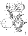
- FIG. 1 an embodiment of a device according to the invention in the form of a drag finishing machine 1a is shown.
- the towing machine 1 a is equipped with a workpiece holder 2, which by means of a clamping connection 3 on a moving - here: rotatable - supporting part 4 of the drag finishing machine 1 a, the so-called plate or Rotor, releasably fixed.
- the workpiece holder 2 is eccentrically clamped with respect to the axis of rotation 4a of the support member 4 at the latter, so that it describes a trajectory during rotation of the support member 4.
- the workpiece holder 2 can in turn be fixed about an axis 2a, such as about its longitudinal axis, rotatable on the support member 4, which can be done for example by means disposed in the support member 4 planetary gear, which upon rotation of the support member 4 about its axis of rotation 4a a rotation of the workpiece holder 2 is induced about its axis of rotation 2a.
- axis 2a such as about its longitudinal axis
- planetary gear which upon rotation of the support member 4 about its axis of rotation 4a a rotation of the workpiece holder 2 is induced about its axis of rotation 2a.
- further workpiece holder (not shown), which can also be tensioned on the underside of the support member 4 in eccentric position to the axis of rotation 4a.
- the workpiece holder 2 can be designed, for example, to receive a plurality of workpieces (not shown) that are essentially vertically tensionable and, for this purpose, face away from the clamping connection 3 with the carrying part 4 at its clamping part 3 Fig. 1 lower side a plurality - in the present case three - workpiece carrier 6 for releasably clamping each of a workpiece or a workpiece holder for clamping each one or more workpieces (each not shown).
- the workpiece carriers 6 are distributed around the circumference of the workpiece holder 2, ie arranged eccentrically with respect to its axis of rotation 2 a.
- the workpiece carrier 6 In order to apply to the workpiece carrier 6 in addition to the translational movement as a result of rotation of the support member 4 and the workpiece holder 2 with a rotational movement about their respective longitudinal axis 6a, the workpiece carrier 6 in turn rotatably mounted on the workpiece holder 2 and for example in turn by means of a arranged in the workpiece holder 2 planetary gear (not shown) to be set in rotation.
- the workpieces that can be fixed to the workpiece carriers 6 of the workpiece holder 2 dip into a working container 8 which is filled with a powdered or particulate abrasive and / or polishing granulate, optionally with the addition of liquid processing aids, such as water, surfactants and the like, is filled.
- a powdered or particulate abrasive and / or polishing granulate optionally with the addition of liquid processing aids, such as water, surfactants and the like, is filled.
- the support part 4 of the towing machine 1a is set in rotation by means of the motor / gear arrangement 5, so that the workpiece holder 2 moves in a certain path of movement - here a circular path - through the working container 8 or dragged by the processing medium contained herein.
- the planetary gear housed in the support part 4 or in the workpiece holder 2 ensure a self-rotation of both the workpiece holder 2 and the workpiece carrier 6 or the workpieces fixed thereto about a substantially vertical axis here, which, however, also by a finite angle in Can be arranged inclined relative to the vertical. Due to the relative movement between the workpieces and the bed of abrasive and / or polishing granules of the processing medium, this leads to a surface treatment of the workpieces.
- controllable rotary drive in conjunction which similar to the in Fig. 2 shown embodiment (see below) may comprise a provided with a driving shaft support plate, the former engages from below in a complementary thereto receiving profile on the underside of the container 8 to provide a rotationally fixed connection with the container 8.
- the towing machine 1 a further comprises one or more sensors 9, which is / are designed to determine the distance between the sensor 9 and the filling level 10 of the grinding and / or polishing granules, by subtracting this distance from a known distance between the Sensor 9 and the workpiece the immersion depth of the same in the container 8 located in the bed of abrasive and / or polishing granules to determine.
- the surface contour of the grinding and / or polishing granules is in Fig. 1 schematically indicated by the dashed line 10 when the container 8 rotates.
- the sensors 9 may be, in particular, non-contact displacement or proximity sensors, such as ultrasound, laser or infrared sensors.
- the distance between the sensor 9 as a reference point and the respective workpiece or the workpiece carrier 6 of the workpiece holder 2, to which the Workpieces are releasably fixed, known it can be determined by simple subtraction, the immersion depth of the workpieces in the granular bed, in particular in real time during the surface treatment.
- the device 1a moreover comprises, in particular, a control device, not shown, in particular in the form of a data processing unit which is in operative connection with the sensors 9 and which is further connected to a lifting device, e.g. in the form of a connected to a control drive 11 threaded spindle 12, is operatively connected to at least raise the plate 4, optionally together with its drive 5, and the workpiece holders 2 fixed thereto with respect to the container 8 or lower, depending on whether the with Help detected by the sensor 9 actual immersion depth exceeds a desired immersion depth or below.
- the control device is furthermore equipped with an input device and a display device (likewise not shown) in order to determine the desired process parameters, such as, in particular, the desired nominal immersion depth, but also e.g. To enter the distance between the sensor 9 and a respective workpiece (or the respective workpiece holder 2 or more precisely: the respective workpiece carrier 6).
- the control device is also expediently equipped with a memory device in order to store various motion programs of the individually desired surface treatment.
- the control device can expediently also with the rotary drive (see. Fig. 2 ) of the container 8 and with the drive 5 of the plate 4 are operatively connected to the processing time of the workpieces and / or the relative speed of the workpiece holders 2 releasably fixed Workpieces with respect to the found in the container 8 bed of abrasive and / or polishing granules depending on the detected by means of the sensor 9 immersion depth of the workpiece holders 2 releasably fixed workpieces in the bed of grinding and / or polishing granules to change.
- the surface treatment can be carried out in a self-regulating manner as a function of the depth of immersion of the workpieces determined by the sensor into the granulate bed.
- Fig. 2 an embodiment of a device according to the invention in the form of a dip-finishing machine 1b is shown, wherein the same or equivalent components with the same reference numerals as in Fig. 1 are provided.
- the dip-finishing machine 1b in turn comprises a container 8 for receiving a grinding and / or polishing granules (not shown), which is rotatable about a vertical axis 8a.
- the container 8 is arranged on a carriage 14 which can be moved by means of rollers 13, in order to ensure a simple and rapid exchange of the granulate, in that a container 8 can be exchanged for another container 8.
- the carriage 14 includes, for example, arranged on its underside, motorized rotary drive (in Fig.
- a equipped with a cam shaft 15 support plate 16 includes, on which the container 8 rotatably and self-centering can be placed.
- the device 1b further comprises in the present case a manipulator in the form of a robot 20, which carries one or more workpiece holder 2 for releasably fixing a workpiece to be machined (not shown).
- the robot 20 is, for example, a multi-axis industrial robot which has a frame 22 on which a carousel 23 is pivotably mounted about a vertical axis.
- a boom 26 is mounted on a horizontal, parallel to the pivot axis of the bracket 24 axis.
- the boom 26 is equipped at its end with a three-axis robot hand 27 which carries the workpiece holder 2. While the carousel 23 is driven by a control motor 28 relative to the stationary frame 22, a control motor 29 for driving the rocker 25 and a control motor 30 for driving the boom 26.
- the three-axis robot hand 27 is of three other control motors 31, 32, 33rd driven, which are mounted, for example, on the robot hand 17 facing away from the end of the boom 26.
- the three-axis robot hand 27 with the workpiece holder 2 consequently allows the latter to pivot under any orientation in three-dimensional space, in order to align a workpiece fastened to the workpiece holder 2 in the desired position with respect to the granulate bed located in the container 8, as well as to move the workpiece holder 2 translationally in any spatial directions.
- the three-axis robot hand 27 can rotate the workpiece holder 2 at least about its longitudinal axis 2a, provided a rotation of the workpiece is desired in addition to a pure immersion grinding process.
- a sensor 9 is mounted, which for determining the distance between the sensor 9 and the level level 10 (FIG. Fig. 1 ) of the grinding and / or polishing granules is formed in order to determine by subtracting this distance from a known distance between the sensor 9 and the workpiece, the immersion depth thereof in the container 8 located in the bed of grinding and / or polishing granules.
- the sensor 9 can according to the according Fig. 1 be educated.
- Both the robot 20 with its control motors 28-33 and arranged on the workpiece holder 2 sensor 9 and the rotational drive of the container 8 are in turn operatively connected to a common control device (not shown), which in turn with an input, a display and a Memory device is connected to various motion programs both the workpiece holder 2 with respect to the rotating container 8 and movement programs of the container 8 itself (here: rotation) to enter, display, process and store.
- a common control device not shown
- a display and a Memory device is connected to various motion programs both the workpiece holder 2 with respect to the rotating container 8 and movement programs of the container 8 itself (here: rotation) to enter, display, process and store.
- control device is detachably fixed to the workpiece holder 2 as a function of the immersion depth detected with the aid of the sensor 9
- Workpiece in the granule bed located in the container 8 controls the robot 20 such that the workpiece holder 2 is raised or lowered with respect to the container 8, provided that the detected by means of the sensor 9 actual immersion depth over a desired target immersion depth or falls below.
- the control device may conveniently be in operative connection with the rotary drive of the container 8 to the processing time of the workpieces and / or the speed of the container 8 in response to the detected by means of the sensor 9 immersion depth of the workpiece holder 2 fixed workpiece in the bed from grinding and / or polishing granules to change.
- any movements of the robot 20 such as with regard to an increase / decrease in the speed of the robot hand 27 with the workpiece holder 2 about the axis 2a.
Landscapes
- Engineering & Computer Science (AREA)
- Mechanical Engineering (AREA)
- Finish Polishing, Edge Sharpening, And Grinding By Specific Grinding Devices (AREA)
Claims (15)
- Procédé pour le traitement de surface de pièces à usiner, dans lequel on plonge la pièce à usiner dans un amas de granulat de ponçage et/ou de polissage se trouvant dans un réservoir (8) et on la déplace dans l'amas de granulat de ponçage et/ou de polissage par rapport à ce dernier, caractérisé en ce que l'on détermine la profondeur de plongée de la pièce à usiner dans l'amas de granulat de ponçage et/ou de polissage à l'occasion du traitement de surface par soustraction de la distance déterminée par capteur entre un capteur (9) disposé au-dessus du réservoir (8) et le niveau de remplissage (10) du granulat de ponçage et/ou de polissage dans le réservoir (8) d'une distance connue entre le capteur (9) et la pièce à usiner.
- Procédé selon la revendication 1, caractérisé en ce que l'on fait tourner au moins le réservoir (8) autour d'un axe essentiellement vertical (8a) pendant le traitement de surface de la pièce à usiner.
- Procédé selon la revendication 1 ou 2, caractérisé en ce que l'on détermine la distance entre le capteur (9) et le niveau de remplissage (10) du granulat de ponçage et/ou de polissage au moyen de capteurs de déplacement et/ou de proximité sans contact (9) ou de palpeurs mécaniques.
- Procédé selon l'une quelconque des revendications 1 à 3, caractérisé en ce que l'on utilise la profondeur de plongée réelle déterminée de la pièce à usiner dans l'amas de granulat de ponçage et/ou de polissage, pour relever ou abaisser la pièce à usiner en fonction de la profondeur de plongée désirée dans l'amas de granulat de ponçage et/ou de polissage.
- Procédé selon l'une quelconque des revendications 1 à 4, caractérisé en ce que l'on utilise la profondeur réelle déterminée, pour modifier au moins un paramètre du groupe comprenant la vitesse relative de la pièce à usiner par rapport à l'amas de granulat de ponçage et/ou de polissage et le temps de traitement en fonction de celle-ci.
- Procédé selon l'une quelconque des revendications 1 à 5, caractérisé en ce que l'on ajoute au granulat de ponçage et/ou de polissage un agent de traitement liquide, dans lequel on commande la quantité d'agent de traitement ajouté.
- Dispositif (1a, 1b) pour le traitement de surface de pièces à usiner par plongée de la pièce à usiner dans un amas de granulat de ponçage et/ou de polissage avec un mouvement relatif de celui-ci par rapport à la pièce à usiner, en particulier pour la mise en oeuvre d'un procédé selon l'une quelconque des revendications précédentes, avec un réservoir (8) destiné à contenir le granulat de ponçage et/ou de polissage et avec un ou plusieurs porte(s)-pièce(s) (2), sur lequel/lesquels les pièces à usiner à traiter peuvent être fixées de façon amovible, dans lequel le/les porte(s)-pièce(s) (2) est/sont mobile(s) par rapport au réservoir (8), caractérisé en ce que le dispositif (1a, 1b) comporte en outre au moins un capteur (9) disposé au-dessus du réservoir (8), qui est conçu pour déterminer la distance entre le capteur (9) et le niveau de remplissage (10) du granulat de ponçage et/ou de polissage, afin de déterminer, par soustraction de cette distance d'une distance connue entre le capteur (9) et la pièce à usiner, la profondeur de plongée de celle-ci dans l'amas de granulat de ponçage et/ou de polissage se trouvant dans le réservoir (8).
- Dispositif selon la revendication 7, caractérisé en ce qu'un entraînement en rotation est associé au réservoir (8), afin de mettre celui-ci en rotation.
- Dispositif selon la revendication 7 ou 8, caractérisé en ce que le porte-pièce (2) est agencé sur une partie (4, 27) mobile, en particulier rotative, par rapport au réservoir (8) destiné à contenir le granulat de ponçage et/ou de polissage.
- Dispositif selon l'une quelconque des revendications 7 à 9, caractérisé en ce que le capteur (9) est formé par un capteur de déplacement et/ou de proximité sans contact, en particulier du groupe des capteurs de déplacement et/ou de proximité inductifs, capacitifs, magnétiques, optiques et électromagnétiques, ou par un capteur mécanique, en particulier un palpeur.
- Dispositif selon la revendication 10, caractérisé en ce que le capteur (9) est une barrière lumineuse, un détecteur à ultrasons, à laser ou à infrarouge, ou un palpeur oscillant.
- Dispositif selon l'une quelconque des revendications 7 à 11, caractérisé en ce que le capteur (9) est disposé au-dessus ou au niveau du porte-pièce (2).
- Dispositif selon l'une quelconque des revendications 7 à 12, caractérisé en ce que le capteur (9) est en liaison active avec un dispositif de commande, qui est en outre en liaison active avec un dispositif de levage (11, 12, 20) associé au porte-pièce (2), pour relever ou abaisser la pièce à usiner, en fonction de la profondeur de plongée réelle dans l'amas de granulat de ponçage et/ou de polissage déterminée à l'aide du capteur (9), en fonction de la profondeur de plongée désirée dans l'amas de granulat de ponçage et/ou de polissage.
- Dispositif selon l'une quelconque des revendications 7 à 13, caractérisé en ce que le capteur (9) est en liaison active avec un dispositif de commande, qui est en outre en liaison active avec un entraînement du réservoir (8) et/ou du porte-pièce (2), afin de- modifier la vitesse relative de la pièce à usiner fixée de façon amovible au porte-pièce (2) par rapport à l'amas de granulat de ponçage et/ou de polissage se trouvant dans le réservoir (8) en fonction de la profondeur de plongée, déterminée à l'aide du capteur (9), de la pièce à usiner fixée de façon amovible au porte-pièce (2) dans l'amas de granulat de ponçage et/ou de polissage; et/ou- modifier le temps de traitement de la pièce à usiner en fonction de la profondeur de plongée, déterminée à l'aide du capteur (9), de la pièce à usiner fixée de façon amovible au porte-pièce (2) dans l'amas de granulat de ponçage et/ou de polissage.
- Dispositif selon l'une quelconque des revendications 7 à 14, caractérisé en ce que le réservoir (8) présente une entrée munie d'une pompe de dosage réglable, afin d'ajouter au granulat de ponçage et/ou de polissage se trouvant dans le réservoir (8) une quantité réglable d'un agent de traitement liquide.
Applications Claiming Priority (1)
| Application Number | Priority Date | Filing Date | Title |
|---|---|---|---|
| DE102011113167A DE102011113167A1 (de) | 2011-09-14 | 2011-09-14 | Verfahren und Vorrichtung zur Oberflächenbearbeitung von Werkstücken |
Publications (2)
| Publication Number | Publication Date |
|---|---|
| EP2572829A1 EP2572829A1 (fr) | 2013-03-27 |
| EP2572829B1 true EP2572829B1 (fr) | 2013-11-20 |
Family
ID=46796239
Family Applications (1)
| Application Number | Title | Priority Date | Filing Date |
|---|---|---|---|
| EP12005929.0A Not-in-force EP2572829B1 (fr) | 2011-09-14 | 2012-08-17 | Procédé et dispositif de traitement de surface de pièces à usiner |
Country Status (3)
| Country | Link |
|---|---|
| EP (1) | EP2572829B1 (fr) |
| CN (1) | CN102990501B (fr) |
| DE (1) | DE102011113167A1 (fr) |
Cited By (3)
| Publication number | Priority date | Publication date | Assignee | Title |
|---|---|---|---|---|
| DE102016104148A1 (de) | 2016-03-08 | 2017-09-14 | Andreas Boigner | Vorrichtung und Verfahren zur Oberflächenbehandlung von Bauteilen |
| CN110774158A (zh) * | 2019-11-13 | 2020-02-11 | 罗厚镇 | 一种数控机床切削刀具钝化装置 |
| DE102019008802A1 (de) * | 2019-12-18 | 2021-06-24 | OTEC Präzisonsfinish GmbH | Verfahren und Vorrichtung zur Oberflächenbearbeitung von Werkstücken |
Families Citing this family (19)
| Publication number | Priority date | Publication date | Assignee | Title |
|---|---|---|---|---|
| DE102012216724B4 (de) * | 2012-09-19 | 2025-05-08 | Carl Zeiss Vision International Gmbh | Verfahren und Vorrichtung zur Polierbearbeitung von Brillenlinsen und Gießformen für die Brillenlinsenherstellung sowie entsprechendes Verfahren zur Herstellung von Brillenlinsen und Gießformen für die Brillenlinsenherstellung |
| KR102218198B1 (ko) * | 2013-04-09 | 2021-02-22 | 오텍 프라지시온스피니쉬 게엠베하 | 피가공물의 표면 처리 방법 및 그 장치 |
| CN104416636B (zh) * | 2013-08-27 | 2017-08-29 | 中集集团集装箱控股有限公司 | 去除竹筒表面竹青的方法及设备 |
| CN104044052B (zh) * | 2014-06-19 | 2017-01-11 | 丹阳市鑫烨光学仪器有限公司 | 一种用散粒制作总型粒子的加工装置 |
| CN104556660B (zh) * | 2015-01-29 | 2017-03-15 | 合肥京东方光电科技有限公司 | 支撑柱的高度调节装置 |
| DE102016103156A1 (de) | 2016-02-23 | 2017-08-24 | db-matik GmbH | Verfahren zur Oberflächenbearbeitung von Werkstücken |
| CN106002587B (zh) * | 2016-05-20 | 2018-02-23 | 五邑大学 | 基于平动圆周转动的工件表面处理设备 |
| CN106670949B (zh) * | 2016-12-26 | 2018-10-02 | 广东迪生力汽配股份有限公司 | 一种轮毂抛光装置及方法 |
| CN107234546A (zh) * | 2017-07-28 | 2017-10-10 | 津上精密机床(浙江)有限公司 | 一种磨床进给控制系统 |
| TWI647038B (zh) * | 2018-04-25 | 2019-01-11 | Hsi-Chih Kuo | 多轉軸研磨設備 |
| CN110405351B (zh) * | 2019-06-29 | 2021-04-27 | 东莞泰升玻璃有限公司 | 一种玻璃表面激光雕刻方法 |
| CN112428088A (zh) * | 2020-11-20 | 2021-03-02 | 中车唐山机车车辆有限公司 | 拉丝设备、工件拉丝的处理方法、控制装置及存储介质 |
| CN112496880A (zh) * | 2020-12-18 | 2021-03-16 | 贵州大学 | 一种气固两相流磨粒刀具钝化设备 |
| DE102021101245A1 (de) | 2021-01-21 | 2022-07-21 | Rösler Holding Gmbh | Verfahren zur überwachung eines gleitschleifprozesses |
| CN115555979B (zh) * | 2022-09-19 | 2024-12-27 | 瑞谷科技(大连)股份有限公司 | 保持架辅助光饰装置 |
| CN115741444B (zh) * | 2022-11-21 | 2023-08-01 | 滁州市成业机械制造股份有限公司 | 一种多级离心泵叶轮用加工机床 |
| CN116276606B (zh) * | 2023-05-04 | 2024-07-02 | 浙江湖磨抛光磨具制造有限公司 | 一种曲轴光整机 |
| CN116426910A (zh) * | 2023-05-08 | 2023-07-14 | 洛阳瑞宝数控设备有限公司 | 一种机床刀具钝化处理设备 |
| CN116871898B (zh) * | 2023-08-11 | 2024-01-26 | 青岛鼎正智能科技有限公司 | 一种用于注塑模具加工的智能化粗铣装置 |
Family Cites Families (10)
| Publication number | Priority date | Publication date | Assignee | Title |
|---|---|---|---|---|
| FR2511628B1 (fr) * | 1981-08-20 | 1985-10-31 | Parker Ste Continentale | Dispositif pour la maintenance d'une installation de tribofinition, et notamment de son lit d'elements abrasifs |
| EP1433569B1 (fr) * | 1997-12-10 | 2006-09-13 | Shuji Kawasaki | Dispositif de tribofinition |
| CA2353694C (fr) * | 1998-11-14 | 2008-03-18 | Mtu Aero Engines Gmbh | Dispositif pour l'usinage de precision de composants a symetrie de revolution |
| DE20005361U1 (de) | 2000-03-23 | 2000-06-15 | OTEC Präzisionsfinish GmbH, 75334 Straubenhardt | Werkstückhalter für Schleppfinishmaschinen |
| DE10204267C1 (de) | 2002-02-02 | 2003-04-24 | Otec Praezisionsfinish Gmbh | Werkstückhalter für Schleppfinishmaschinen |
| WO2004050304A1 (fr) * | 2002-11-29 | 2004-06-17 | Sintobrator,Ltd. | Procede de polissage d'un fut et dispositif de polissage de futs |
| DE102009004916B4 (de) | 2009-01-16 | 2014-05-22 | Otec Präzisionsfinish GmbH | Verfahren zur Oberflächenbearbeitung von Werkstücken unter Verwendung eines mit Zuschlagstoffen beaufschlagten, flüssigen Bearbeitungsmediums und Bearbeitungsmedium mit solchen Zuschlagstoffen |
| DE102009021824A1 (de) * | 2009-05-18 | 2010-11-25 | Rolls-Royce Deutschland Ltd & Co Kg | Verfahren zum Kantenentgraten und -verrunden |
| CN201632923U (zh) * | 2009-09-18 | 2010-11-17 | 廊坊市北方天宇机电技术有限公司 | 一种旋转主轴式光整机 |
| CN102107377A (zh) * | 2009-12-23 | 2011-06-29 | 沈阳黎明航空发动机(集团)有限责任公司 | 一种整体叶盘双驱动轴复合自动光整加工方法 |
-
2011
- 2011-09-14 DE DE102011113167A patent/DE102011113167A1/de not_active Withdrawn
-
2012
- 2012-08-17 EP EP12005929.0A patent/EP2572829B1/fr not_active Not-in-force
- 2012-09-12 CN CN201210336803.5A patent/CN102990501B/zh not_active Expired - Fee Related
Cited By (4)
| Publication number | Priority date | Publication date | Assignee | Title |
|---|---|---|---|---|
| DE102016104148A1 (de) | 2016-03-08 | 2017-09-14 | Andreas Boigner | Vorrichtung und Verfahren zur Oberflächenbehandlung von Bauteilen |
| CN110774158A (zh) * | 2019-11-13 | 2020-02-11 | 罗厚镇 | 一种数控机床切削刀具钝化装置 |
| DE102019008802A1 (de) * | 2019-12-18 | 2021-06-24 | OTEC Präzisonsfinish GmbH | Verfahren und Vorrichtung zur Oberflächenbearbeitung von Werkstücken |
| WO2021122736A1 (fr) | 2019-12-18 | 2021-06-24 | Otec Präzisionsfinish GmbH | Procédé et dispositif pour le traitement de la surface de pièces |
Also Published As
| Publication number | Publication date |
|---|---|
| EP2572829A1 (fr) | 2013-03-27 |
| CN102990501A (zh) | 2013-03-27 |
| DE102011113167A1 (de) | 2013-03-14 |
| CN102990501B (zh) | 2016-11-23 |
Similar Documents
| Publication | Publication Date | Title |
|---|---|---|
| EP2572829B1 (fr) | Procédé et dispositif de traitement de surface de pièces à usiner | |
| EP2983864B1 (fr) | Procédé et dispositif de traitement de surface de pièces | |
| EP2161092B1 (fr) | Machine à meuler des roues dentées et procédé de dressage d'un outil de meulage | |
| DE102010052222A1 (de) | Vorrichtung zur Oberflächenbearbeitung von Werkstücken, insbesondere Schleppfinishmaschine | |
| DE102012006502A1 (de) | Verfahren zum mehrstufigen Schleifen von Werkstücken, sowie Vakuumtisch, Vorratsbehälter, Abstreifeinrichtung und Anlage zur Durchführung des Verfahrens | |
| DE3010964C2 (de) | Verfahren und Vorrichtung zum Entleeren von Hohlräume aufweisenden Werkstücken | |
| EP1860241A3 (fr) | Engin de travaux publics automoteur ainsi que procédé de traitement de sols | |
| DE102011015750A1 (de) | Verfahren und Vorrichtung zur Oberflächenbearbeitung von Werkstücken | |
| EP1827755B1 (fr) | Dispositif servant a polir des surfaces dures, en particulier des surfaces de verre | |
| DE102012025233B4 (de) | Schlepp- und/oder Tauchfinishmaschine zur Oberflächenbearbeitung von Werkstücken mittels Schleif- und/oder Poliergranulat in Gegenwart eines flüssigen Bearbeitungsmediums | |
| DE19804885C5 (de) | Vorrichtung zum Superfinishen | |
| DE112015002319T5 (de) | Planarisierungsbearbeitungsverfahren und Planarisierungsbearbeitungsvorrichtung | |
| DE216197T1 (de) | Fraes- oder schleifmaschine zum endbearbeiten flacher oberflaechen aus stein, beton oder aehnlichem harten material. | |
| DE102010049919B4 (de) | Verfahren und Vorrichtung zur Oberflächenbearbeitung von Durchgangsbohrungen aufweisenden Werkstücken | |
| DE102013006010A1 (de) | Verfahren und Vorrichtung zur Oberflächenbearbeitung von Werkstücken | |
| EP0054214B1 (fr) | Procédé de dressage de meules et dispositif à cet effet | |
| DE3719980A1 (de) | Reparatur von hydraulikzylindern fuer ausbauschilde | |
| DE4423376A1 (de) | Fahrzeug zum Strahlen von ebenen, gekrümmten und strukturierten Flächen | |
| EP0131141B1 (fr) | Finissage à mouvement traînant et dispositif pour sa mise en oeuvre | |
| DE2805429A1 (de) | Werkstoffabtragemaschine | |
| DE102021107857A1 (de) | Verfahren und Vorrichtung zur lokalen Oberflächenbearbeitung von Werkstücken | |
| CN112428033A (zh) | 一种自动检测磨砂轮形变程度的轴承磨削机 | |
| EP3206835A1 (fr) | Dispositif de rectification cylindrique sans centre et procédé d'utilisation d'un tel dispositif | |
| DE202014009163U1 (de) | Vorrichtung zum spitzenlosen Rundschleifen | |
| DE102019007889A1 (de) | Verfahren zum lösbaren Festlegen eines Werkstückes an einer Spanneinrichtung, Spanneinrichtung und Werkzeugmaschine mit einer solchen Spanneinrichtung |
Legal Events
| Date | Code | Title | Description |
|---|---|---|---|
| PUAI | Public reference made under article 153(3) epc to a published international application that has entered the european phase |
Free format text: ORIGINAL CODE: 0009012 |
|
| AK | Designated contracting states |
Kind code of ref document: A1 Designated state(s): AL AT BE BG CH CY CZ DE DK EE ES FI FR GB GR HR HU IE IS IT LI LT LU LV MC MK MT NL NO PL PT RO RS SE SI SK SM TR |
|
| AX | Request for extension of the european patent |
Extension state: BA ME |
|
| 17P | Request for examination filed |
Effective date: 20130522 |
|
| RBV | Designated contracting states (corrected) |
Designated state(s): AL AT BE BG CH CY CZ DE DK EE ES FI FR GB GR HR HU IE IS IT LI LT LU LV MC MK MT NL NO PL PT RO RS SE SI SK SM TR |
|
| GRAP | Despatch of communication of intention to grant a patent |
Free format text: ORIGINAL CODE: EPIDOSNIGR1 |
|
| INTG | Intention to grant announced |
Effective date: 20130813 |
|
| GRAS | Grant fee paid |
Free format text: ORIGINAL CODE: EPIDOSNIGR3 |
|
| GRAA | (expected) grant |
Free format text: ORIGINAL CODE: 0009210 |
|
| AK | Designated contracting states |
Kind code of ref document: B1 Designated state(s): AL AT BE BG CH CY CZ DE DK EE ES FI FR GB GR HR HU IE IS IT LI LT LU LV MC MK MT NL NO PL PT RO RS SE SI SK SM TR |
|
| REG | Reference to a national code |
Ref country code: GB Ref legal event code: FG4D Free format text: NOT ENGLISH |
|
| REG | Reference to a national code |
Ref country code: CH Ref legal event code: EP |
|
| REG | Reference to a national code |
Ref country code: AT Ref legal event code: REF Ref document number: 641307 Country of ref document: AT Kind code of ref document: T Effective date: 20131215 |
|
| REG | Reference to a national code |
Ref country code: IE Ref legal event code: FG4D Free format text: LANGUAGE OF EP DOCUMENT: GERMAN |
|
| REG | Reference to a national code |
Ref country code: DE Ref legal event code: R096 Ref document number: 502012000213 Country of ref document: DE Effective date: 20140116 |
|
| REG | Reference to a national code |
Ref country code: NL Ref legal event code: VDEP Effective date: 20131120 |
|
| REG | Reference to a national code |
Ref country code: LT Ref legal event code: MG4D |
|
| PG25 | Lapsed in a contracting state [announced via postgrant information from national office to epo] |
Ref country code: HR Free format text: LAPSE BECAUSE OF FAILURE TO SUBMIT A TRANSLATION OF THE DESCRIPTION OR TO PAY THE FEE WITHIN THE PRESCRIBED TIME-LIMIT Effective date: 20131120 Ref country code: LT Free format text: LAPSE BECAUSE OF FAILURE TO SUBMIT A TRANSLATION OF THE DESCRIPTION OR TO PAY THE FEE WITHIN THE PRESCRIBED TIME-LIMIT Effective date: 20131120 Ref country code: IS Free format text: LAPSE BECAUSE OF FAILURE TO SUBMIT A TRANSLATION OF THE DESCRIPTION OR TO PAY THE FEE WITHIN THE PRESCRIBED TIME-LIMIT Effective date: 20140320 Ref country code: SE Free format text: LAPSE BECAUSE OF FAILURE TO SUBMIT A TRANSLATION OF THE DESCRIPTION OR TO PAY THE FEE WITHIN THE PRESCRIBED TIME-LIMIT Effective date: 20131120 Ref country code: NO Free format text: LAPSE BECAUSE OF FAILURE TO SUBMIT A TRANSLATION OF THE DESCRIPTION OR TO PAY THE FEE WITHIN THE PRESCRIBED TIME-LIMIT Effective date: 20140220 Ref country code: FI Free format text: LAPSE BECAUSE OF FAILURE TO SUBMIT A TRANSLATION OF THE DESCRIPTION OR TO PAY THE FEE WITHIN THE PRESCRIBED TIME-LIMIT Effective date: 20131120 Ref country code: NL Free format text: LAPSE BECAUSE OF FAILURE TO SUBMIT A TRANSLATION OF THE DESCRIPTION OR TO PAY THE FEE WITHIN THE PRESCRIBED TIME-LIMIT Effective date: 20131120 |
|
| PG25 | Lapsed in a contracting state [announced via postgrant information from national office to epo] |
Ref country code: LV Free format text: LAPSE BECAUSE OF FAILURE TO SUBMIT A TRANSLATION OF THE DESCRIPTION OR TO PAY THE FEE WITHIN THE PRESCRIBED TIME-LIMIT Effective date: 20131120 Ref country code: RS Free format text: LAPSE BECAUSE OF FAILURE TO SUBMIT A TRANSLATION OF THE DESCRIPTION OR TO PAY THE FEE WITHIN THE PRESCRIBED TIME-LIMIT Effective date: 20131120 Ref country code: ES Free format text: LAPSE BECAUSE OF FAILURE TO SUBMIT A TRANSLATION OF THE DESCRIPTION OR TO PAY THE FEE WITHIN THE PRESCRIBED TIME-LIMIT Effective date: 20131120 |
|
| PG25 | Lapsed in a contracting state [announced via postgrant information from national office to epo] |
Ref country code: PT Free format text: LAPSE BECAUSE OF FAILURE TO SUBMIT A TRANSLATION OF THE DESCRIPTION OR TO PAY THE FEE WITHIN THE PRESCRIBED TIME-LIMIT Effective date: 20140320 |
|
| PG25 | Lapsed in a contracting state [announced via postgrant information from national office to epo] |
Ref country code: EE Free format text: LAPSE BECAUSE OF FAILURE TO SUBMIT A TRANSLATION OF THE DESCRIPTION OR TO PAY THE FEE WITHIN THE PRESCRIBED TIME-LIMIT Effective date: 20131120 |
|
| REG | Reference to a national code |
Ref country code: DE Ref legal event code: R097 Ref document number: 502012000213 Country of ref document: DE |
|
| PG25 | Lapsed in a contracting state [announced via postgrant information from national office to epo] |
Ref country code: RO Free format text: LAPSE BECAUSE OF FAILURE TO SUBMIT A TRANSLATION OF THE DESCRIPTION OR TO PAY THE FEE WITHIN THE PRESCRIBED TIME-LIMIT Effective date: 20131120 Ref country code: SK Free format text: LAPSE BECAUSE OF FAILURE TO SUBMIT A TRANSLATION OF THE DESCRIPTION OR TO PAY THE FEE WITHIN THE PRESCRIBED TIME-LIMIT Effective date: 20131120 Ref country code: PL Free format text: LAPSE BECAUSE OF FAILURE TO SUBMIT A TRANSLATION OF THE DESCRIPTION OR TO PAY THE FEE WITHIN THE PRESCRIBED TIME-LIMIT Effective date: 20131120 Ref country code: CZ Free format text: LAPSE BECAUSE OF FAILURE TO SUBMIT A TRANSLATION OF THE DESCRIPTION OR TO PAY THE FEE WITHIN THE PRESCRIBED TIME-LIMIT Effective date: 20131120 |
|
| PLBE | No opposition filed within time limit |
Free format text: ORIGINAL CODE: 0009261 |
|
| STAA | Information on the status of an ep patent application or granted ep patent |
Free format text: STATUS: NO OPPOSITION FILED WITHIN TIME LIMIT |
|
| PG25 | Lapsed in a contracting state [announced via postgrant information from national office to epo] |
Ref country code: DK Free format text: LAPSE BECAUSE OF FAILURE TO SUBMIT A TRANSLATION OF THE DESCRIPTION OR TO PAY THE FEE WITHIN THE PRESCRIBED TIME-LIMIT Effective date: 20131120 |
|
| 26N | No opposition filed |
Effective date: 20140821 |
|
| REG | Reference to a national code |
Ref country code: DE Ref legal event code: R097 Ref document number: 502012000213 Country of ref document: DE Effective date: 20140821 |
|
| PG25 | Lapsed in a contracting state [announced via postgrant information from national office to epo] |
Ref country code: SI Free format text: LAPSE BECAUSE OF FAILURE TO SUBMIT A TRANSLATION OF THE DESCRIPTION OR TO PAY THE FEE WITHIN THE PRESCRIBED TIME-LIMIT Effective date: 20131120 |
|
| PG25 | Lapsed in a contracting state [announced via postgrant information from national office to epo] |
Ref country code: LU Free format text: LAPSE BECAUSE OF FAILURE TO SUBMIT A TRANSLATION OF THE DESCRIPTION OR TO PAY THE FEE WITHIN THE PRESCRIBED TIME-LIMIT Effective date: 20140817 Ref country code: MC Free format text: LAPSE BECAUSE OF FAILURE TO SUBMIT A TRANSLATION OF THE DESCRIPTION OR TO PAY THE FEE WITHIN THE PRESCRIBED TIME-LIMIT Effective date: 20131120 |
|
| REG | Reference to a national code |
Ref country code: IE Ref legal event code: MM4A |
|
| PG25 | Lapsed in a contracting state [announced via postgrant information from national office to epo] |
Ref country code: IE Free format text: LAPSE BECAUSE OF NON-PAYMENT OF DUE FEES Effective date: 20140817 |
|
| REG | Reference to a national code |
Ref country code: CH Ref legal event code: PL |
|
| PG25 | Lapsed in a contracting state [announced via postgrant information from national office to epo] |
Ref country code: LI Free format text: LAPSE BECAUSE OF NON-PAYMENT OF DUE FEES Effective date: 20150831 Ref country code: CH Free format text: LAPSE BECAUSE OF NON-PAYMENT OF DUE FEES Effective date: 20150831 |
|
| PG25 | Lapsed in a contracting state [announced via postgrant information from national office to epo] |
Ref country code: SM Free format text: LAPSE BECAUSE OF FAILURE TO SUBMIT A TRANSLATION OF THE DESCRIPTION OR TO PAY THE FEE WITHIN THE PRESCRIBED TIME-LIMIT Effective date: 20131120 |
|
| PG25 | Lapsed in a contracting state [announced via postgrant information from national office to epo] |
Ref country code: BG Free format text: LAPSE BECAUSE OF FAILURE TO SUBMIT A TRANSLATION OF THE DESCRIPTION OR TO PAY THE FEE WITHIN THE PRESCRIBED TIME-LIMIT Effective date: 20131120 Ref country code: GR Free format text: LAPSE BECAUSE OF FAILURE TO SUBMIT A TRANSLATION OF THE DESCRIPTION OR TO PAY THE FEE WITHIN THE PRESCRIBED TIME-LIMIT Effective date: 20140221 Ref country code: MT Free format text: LAPSE BECAUSE OF FAILURE TO SUBMIT A TRANSLATION OF THE DESCRIPTION OR TO PAY THE FEE WITHIN THE PRESCRIBED TIME-LIMIT Effective date: 20131120 Ref country code: CY Free format text: LAPSE BECAUSE OF FAILURE TO SUBMIT A TRANSLATION OF THE DESCRIPTION OR TO PAY THE FEE WITHIN THE PRESCRIBED TIME-LIMIT Effective date: 20131120 |
|
| PG25 | Lapsed in a contracting state [announced via postgrant information from national office to epo] |
Ref country code: HU Free format text: LAPSE BECAUSE OF FAILURE TO SUBMIT A TRANSLATION OF THE DESCRIPTION OR TO PAY THE FEE WITHIN THE PRESCRIBED TIME-LIMIT; INVALID AB INITIO Effective date: 20120817 Ref country code: BE Free format text: LAPSE BECAUSE OF FAILURE TO SUBMIT A TRANSLATION OF THE DESCRIPTION OR TO PAY THE FEE WITHIN THE PRESCRIBED TIME-LIMIT Effective date: 20140831 |
|
| REG | Reference to a national code |
Ref country code: FR Ref legal event code: PLFP Year of fee payment: 5 |
|
| GBPC | Gb: european patent ceased through non-payment of renewal fee |
Effective date: 20160817 |
|
| PG25 | Lapsed in a contracting state [announced via postgrant information from national office to epo] |
Ref country code: GB Free format text: LAPSE BECAUSE OF NON-PAYMENT OF DUE FEES Effective date: 20160817 |
|
| REG | Reference to a national code |
Ref country code: FR Ref legal event code: PLFP Year of fee payment: 6 |
|
| PG25 | Lapsed in a contracting state [announced via postgrant information from national office to epo] |
Ref country code: MK Free format text: LAPSE BECAUSE OF FAILURE TO SUBMIT A TRANSLATION OF THE DESCRIPTION OR TO PAY THE FEE WITHIN THE PRESCRIBED TIME-LIMIT Effective date: 20131120 |
|
| REG | Reference to a national code |
Ref country code: FR Ref legal event code: PLFP Year of fee payment: 7 |
|
| REG | Reference to a national code |
Ref country code: AT Ref legal event code: MM01 Ref document number: 641307 Country of ref document: AT Kind code of ref document: T Effective date: 20170817 |
|
| PG25 | Lapsed in a contracting state [announced via postgrant information from national office to epo] |
Ref country code: AL Free format text: LAPSE BECAUSE OF FAILURE TO SUBMIT A TRANSLATION OF THE DESCRIPTION OR TO PAY THE FEE WITHIN THE PRESCRIBED TIME-LIMIT Effective date: 20131120 |
|
| PG25 | Lapsed in a contracting state [announced via postgrant information from national office to epo] |
Ref country code: AT Free format text: LAPSE BECAUSE OF NON-PAYMENT OF DUE FEES Effective date: 20170817 |
|
| PGFP | Annual fee paid to national office [announced via postgrant information from national office to epo] |
Ref country code: FR Payment date: 20190830 Year of fee payment: 8 Ref country code: TR Payment date: 20190805 Year of fee payment: 8 Ref country code: IT Payment date: 20190821 Year of fee payment: 8 Ref country code: DE Payment date: 20190821 Year of fee payment: 8 |
|
| REG | Reference to a national code |
Ref country code: DE Ref legal event code: R119 Ref document number: 502012000213 Country of ref document: DE |
|
| PG25 | Lapsed in a contracting state [announced via postgrant information from national office to epo] |
Ref country code: FR Free format text: LAPSE BECAUSE OF NON-PAYMENT OF DUE FEES Effective date: 20200831 Ref country code: IT Free format text: LAPSE BECAUSE OF NON-PAYMENT OF DUE FEES Effective date: 20200817 Ref country code: DE Free format text: LAPSE BECAUSE OF NON-PAYMENT OF DUE FEES Effective date: 20210302 |
|
| PG25 | Lapsed in a contracting state [announced via postgrant information from national office to epo] |
Ref country code: TR Free format text: LAPSE BECAUSE OF NON-PAYMENT OF DUE FEES Effective date: 20200817 |