EP2571636B1 - Verfahren zum herstellen eines abgasschalldämpfers für brennkraftmaschinen - Google Patents
Verfahren zum herstellen eines abgasschalldämpfers für brennkraftmaschinen Download PDFInfo
- Publication number
- EP2571636B1 EP2571636B1 EP11724995.3A EP11724995A EP2571636B1 EP 2571636 B1 EP2571636 B1 EP 2571636B1 EP 11724995 A EP11724995 A EP 11724995A EP 2571636 B1 EP2571636 B1 EP 2571636B1
- Authority
- EP
- European Patent Office
- Prior art keywords
- shell
- outer contour
- contour
- peripheral region
- deep
- Prior art date
- Legal status (The legal status is an assumption and is not a legal conclusion. Google has not performed a legal analysis and makes no representation as to the accuracy of the status listed.)
- Not-in-force
Links
Images


Classifications
-
- B—PERFORMING OPERATIONS; TRANSPORTING
- B21—MECHANICAL METAL-WORKING WITHOUT ESSENTIALLY REMOVING MATERIAL; PUNCHING METAL
- B21D—WORKING OR PROCESSING OF SHEET METAL OR METAL TUBES, RODS OR PROFILES WITHOUT ESSENTIALLY REMOVING MATERIAL; PUNCHING METAL
- B21D22/00—Shaping without cutting, by stamping, spinning, or deep-drawing
- B21D22/20—Deep-drawing
-
- B—PERFORMING OPERATIONS; TRANSPORTING
- B21—MECHANICAL METAL-WORKING WITHOUT ESSENTIALLY REMOVING MATERIAL; PUNCHING METAL
- B21D—WORKING OR PROCESSING OF SHEET METAL OR METAL TUBES, RODS OR PROFILES WITHOUT ESSENTIALLY REMOVING MATERIAL; PUNCHING METAL
- B21D22/00—Shaping without cutting, by stamping, spinning, or deep-drawing
- B21D22/20—Deep-drawing
- B21D22/26—Deep-drawing for making peculiarly, e.g. irregularly, shaped articles
-
- B—PERFORMING OPERATIONS; TRANSPORTING
- B21—MECHANICAL METAL-WORKING WITHOUT ESSENTIALLY REMOVING MATERIAL; PUNCHING METAL
- B21D—WORKING OR PROCESSING OF SHEET METAL OR METAL TUBES, RODS OR PROFILES WITHOUT ESSENTIALLY REMOVING MATERIAL; PUNCHING METAL
- B21D51/00—Making hollow objects
- B21D51/16—Making hollow objects characterised by the use of the objects
- B21D51/18—Making hollow objects characterised by the use of the objects vessels, e.g. tubs, vats, tanks, sinks, or the like
-
- B—PERFORMING OPERATIONS; TRANSPORTING
- B21—MECHANICAL METAL-WORKING WITHOUT ESSENTIALLY REMOVING MATERIAL; PUNCHING METAL
- B21D—WORKING OR PROCESSING OF SHEET METAL OR METAL TUBES, RODS OR PROFILES WITHOUT ESSENTIALLY REMOVING MATERIAL; PUNCHING METAL
- B21D53/00—Making other particular articles
- B21D53/88—Making other particular articles other parts for vehicles, e.g. cowlings, mudguards
-
- F—MECHANICAL ENGINEERING; LIGHTING; HEATING; WEAPONS; BLASTING
- F01—MACHINES OR ENGINES IN GENERAL; ENGINE PLANTS IN GENERAL; STEAM ENGINES
- F01N—GAS-FLOW SILENCERS OR EXHAUST APPARATUS FOR MACHINES OR ENGINES IN GENERAL; GAS-FLOW SILENCERS OR EXHAUST APPARATUS FOR INTERNAL-COMBUSTION ENGINES
- F01N13/00—Exhaust or silencing apparatus characterised by constructional features
- F01N13/18—Construction facilitating manufacture, assembly, or disassembly
- F01N13/1872—Construction facilitating manufacture, assembly, or disassembly the assembly using stamp-formed parts or otherwise deformed sheet-metal
-
- B—PERFORMING OPERATIONS; TRANSPORTING
- B21—MECHANICAL METAL-WORKING WITHOUT ESSENTIALLY REMOVING MATERIAL; PUNCHING METAL
- B21D—WORKING OR PROCESSING OF SHEET METAL OR METAL TUBES, RODS OR PROFILES WITHOUT ESSENTIALLY REMOVING MATERIAL; PUNCHING METAL
- B21D22/00—Shaping without cutting, by stamping, spinning, or deep-drawing
- B21D22/20—Deep-drawing
- B21D22/22—Deep-drawing with devices for holding the edge of the blanks
-
- F—MECHANICAL ENGINEERING; LIGHTING; HEATING; WEAPONS; BLASTING
- F01—MACHINES OR ENGINES IN GENERAL; ENGINE PLANTS IN GENERAL; STEAM ENGINES
- F01N—GAS-FLOW SILENCERS OR EXHAUST APPARATUS FOR MACHINES OR ENGINES IN GENERAL; GAS-FLOW SILENCERS OR EXHAUST APPARATUS FOR INTERNAL-COMBUSTION ENGINES
- F01N13/00—Exhaust or silencing apparatus characterised by constructional features
- F01N13/18—Construction facilitating manufacture, assembly, or disassembly
- F01N13/1861—Construction facilitating manufacture, assembly, or disassembly the assembly using parts formed by casting or moulding
-
- F—MECHANICAL ENGINEERING; LIGHTING; HEATING; WEAPONS; BLASTING
- F01—MACHINES OR ENGINES IN GENERAL; ENGINE PLANTS IN GENERAL; STEAM ENGINES
- F01N—GAS-FLOW SILENCERS OR EXHAUST APPARATUS FOR MACHINES OR ENGINES IN GENERAL; GAS-FLOW SILENCERS OR EXHAUST APPARATUS FOR INTERNAL-COMBUSTION ENGINES
- F01N13/00—Exhaust or silencing apparatus characterised by constructional features
- F01N13/18—Construction facilitating manufacture, assembly, or disassembly
- F01N13/1888—Construction facilitating manufacture, assembly, or disassembly the housing of the assembly consisting of two or more parts, e.g. two half-shells
-
- F—MECHANICAL ENGINEERING; LIGHTING; HEATING; WEAPONS; BLASTING
- F01—MACHINES OR ENGINES IN GENERAL; ENGINE PLANTS IN GENERAL; STEAM ENGINES
- F01N—GAS-FLOW SILENCERS OR EXHAUST APPARATUS FOR MACHINES OR ENGINES IN GENERAL; GAS-FLOW SILENCERS OR EXHAUST APPARATUS FOR INTERNAL-COMBUSTION ENGINES
- F01N13/00—Exhaust or silencing apparatus characterised by constructional features
- F01N13/18—Construction facilitating manufacture, assembly, or disassembly
- F01N13/1888—Construction facilitating manufacture, assembly, or disassembly the housing of the assembly consisting of two or more parts, e.g. two half-shells
- F01N13/1894—Construction facilitating manufacture, assembly, or disassembly the housing of the assembly consisting of two or more parts, e.g. two half-shells the parts being assembled in longitudinal direction
Definitions
- the invention relates to a method for determining an inner and / or outer contour K Si , K Sa of an edge region B S of a shell for producing a muffler.
- a method for determining an inner and / or outer contour K Si , K Sa of an edge region B S of a shell for producing a muffler is eg in the CA-A-2058136 disclosed.
- CA 2,058,136 is formed from a pair of shell molds, wherein the two shell molds are crimped for connection to an edge surface.
- tongues are provided, which serve for fastening a heat shield. The tongues are placed in excess areas of the respective shell mold, which would otherwise be cut off during cutting.
- the DE 20 2008 016 200 U1 describes a two-part muffler whose basic shape has two corner regions, which are each extended beyond the length of the basic shape. With regard to the width, however, the corner areas are back relative to the basic shape. An optimized utilization of the sheet metal strip to be deformed is thus not achieved.
- a shell muffler which, unlike a rectangular basic shape, has two corner regions which are widened in relation to the width of the rectangular basic shape.
- a shell muffler which has several formations in the edge region for the purpose of forming an input or output dome for connecting an exhaust pipe.
- the respective shape protrudes beyond the rectangular basic shape.
- a pot silencer which is formed of two pot halves, which are connected using one or more shelves in the longitudinal direction.
- an off-center opening for the purpose of forming a collar for connecting an exhaust pipe is provided.
- a draft is assigned to the passage over a partial circumference.
- the invention has the object of providing a method for producing a muffler from mold shells in such a way that a material savings and improved acoustic performance are guaranteed.
- a box-shaped inner contour may be a method for producing a shell muffler for an internal combustion engine, which is formed of a first shell and at least a second shell, which to form said shell muffler circulating on the respective edge region B S are connected, K Si having four corner regions E1 - E4 and a width B and a length L and an outer contour K Sa and the respective shell is made from a shell blank R formed by forming a sheet metal strip by using a mold having the shape of the shell, wherein the blank R after forming has an edge region B R with an outer contour K R , and the edge region B R in the subsequent Cutting the blank R to form an outer contour K Sa of the edge portion B S of the shell is at least partially cut using an inner and / or outer contour K Si , K Sa , determined according to the method described above.
- either the inner contour K Si of the edge region B S of the shell is provided in addition to the box-shaped basic shape G with at least one corner region E1 - E4, which is extended beyond the width B and the length L and thus at least partially to the outer contour K R of adapted to be trimmed edge region B R of the blank R and / or provided on the respective shell a molding A for forming an input or output dome for connecting an exhaust pipe, the molding A after forming relative to the basic shape G of the inner contour K Si of the edge region B S of the shell protrudes by a depth t1, wherein the depth t1 is selected such that in order to form the shape A, the size of the sheet metal strip must not be larger than in the absence of the molding A.
- the edge region B to be cut off R of the blank in order to form the inner or outer contour K Si , KS a of the shell altogether gleichblei Bender is formed so that there is a material saving.
- the volume of the respective shell can be increased overall.
- the shell can be made less broad or less long overall in order to keep the same volume, which is accompanied by further material savings.
- the metal strip used for deep drawing or the corresponding coil may be formed narrower.
- a recess E is provided, which is provided in addition to the sidecut T, wherein the indentation E relative to the basic shape G of the inner contour K Si of the edge portion B S of the shell by a depth t2 is lagging behind.
- the respective shell at least in the region of a longitudinal or transverse edge, has the shape A for an input or output dome.
- the features described above relating to the maximum depth t1 of this configuration A ensure the previously described savings regarding the width or length of the metal strip used.
- Due to the inventively provided indentation E the formation of a shape A is possible, which has a desired height h.
- the indentation E ensures an increase in the size or height h of the shape A beyond the waisting T of the basic shape G addition.
- the indentation E is provided in addition to the sidecut T.
- the height h of the formation A can reach the total depth t1 plus t2. After the trimming of the shell, the depth t1 decreases and can also become zero when the formation is trimmed at the level of the inner contour K Si .
- the outer contour K Sa has a shape deviating from the inner contour K Si .
- the inner contour K Si and the outer contour K Sa each other.
- the outer contour K Sa can be adjusted beyond the extension of the inner contour K Si to the contour K R of the blank or its corner regions, so that the acoustic properties can be favorably influenced.
- the inner contour K Si and / or the outer contour K Sa of the edge region B S of the shell is formed from a first longitudinal edge L1, a second longitudinal edge L2, a first transverse edge Q1 and a second transverse edge Q2 and the four corner regions E1, E2, E3, E4, wherein the respective corner region E1, E2, E3, E4 connects a longitudinal edge L1, L2 with a transverse edge Q1, Q2 and the edge region B S of the shell at least in the region of a longitudinal edge L1, L2 and / or a Transverse edge Q1, Q2 has a sidecut T, which extends over at least 50% to 80% of a width w1 and / or a width w2 of the shell.
- the picking up of a shape with a sidecut T is advantageous.
- a sidecut is accompanied by the fact that the shell is narrower or shorter in the area of the sidecut than in the area of the respective corner, which justify the beginning and end of the sidecut.
- the upper limit of the sidecut is probably in the range of 90% to 95%, depending on the radius of the corner to be applied. At 100% waist ratio no waist is no longer available.
- the inner contour K Si and / or the outer contour K Sa of the edge region B S of the shell in the region of both longitudinal edges L1, L2 and / or in the region of both transverse edges Q1, Q2 has the sidecut T.
- the waist can optionally be provided at different longitudinal or transverse edges. This is depending on the desired design and the associated resonance behavior on the one hand and the desired material savings to decide on the other hand. It may be favorable if the sidecut is provided both on both longitudinal and on both transverse edges, so that overall the aforementioned advantages add up to a maximum.
- the inner contour K Si and / or the outer contour K Sa of the edge region B S of the shell establishes a bone-shaped basic shape G.
- the waist is provided on all four longitudinal edges, resulting in an exemplary embodiment bone-shaped basic shape G, due to the extended corner areas the previously described maximum volume while minimizing the width of the sheet metal strip used on the one hand and minimizing the length of the metal strip to be used guaranteed on the other hand.
- a first shell 1.1 of a shell muffler 1 is formed by deep-drawing a metal strip 2, which is formed rectangular starting from a metal strip coil.
- a desired contour K S of the shell 1.1 with a basic shape G
- the after Fig. 1 box-shaped, that is rectangular formed with rounded corners a so-called blank R is first obtained, the edge of which has a contour K R , on the one hand deviates from the rectangular shape of the sheet metal strip 2 and on the other hand deviates from the desired box-shaped contour K S of the shell 1.1.
- the contour K R of the blank R is also referred to as bone-shaped, since in the region of the respective corner the remaining edge to be cut off for the purpose of forming the contour K S or outer contour K Sa of the shell 1.1 is substantially larger than in the region between the respective corner.
- the shell 1.1 or contour K S has a basic shape G, in which corner regions E1-E4 are widened beyond the width B and the length L, so that the contour K S is at least partially adjacent to the contour K R of the edge region to be trimmed B R of the blank R is adjusted.
- the contour K S or the basic shape G has a sidecut T.
- the distance is the two longitudinal edges L1, L2 and the two transverse edges Q1, Q2 smaller than a length w1 of the shell 1.1 and a width w2 of the shell 1.1.
- the shell 1.1 shown here has in the region of its longitudinal edge L2 a shape A for an input or output calotte 1.3 after Fig. 4 on.
- a depression E of the depth t2 is provided in the region of the formation A.
- the indentation E is essentially formed from a rounding radius V R 1 and an adjoining connecting portion V A 1.
- the indentation E is provided in addition to the sidecut T.
- the shape A extends over the aforementioned rounding radius V R 1 and the adjoining connecting portion V A 1 and a subsequent rounding radius V R 2 over a height h.
- the formation A projects in the region of the longitudinal edge L2 only over a depth t1 beyond the bone-shaped inner contour K Si of the shell 1.1.
- the depth t1 is selected such that the sheet-metal strip 2 does not have to be chosen wider because of the shape A than in the case without shape A.
- the depth t1 accordingly corresponds approximately to the thickness of the edge region B S or the height of the rounding radius V R 2 which adjoins the connecting portion V A 1 and the rounding radius V R 1 of the molding A. Consequently, the shape A ends approximately at the level of the outer contour K Sa.
- the waist T runs over approximately 84% of the length w1 and 66% of the width w2.
- the sidecut T may also be provided only on a part of the respective longitudinal or transverse edges L1 to Q2.
- FIG. 2b Sectional view SS off Fig. 2a (Partial sectional right half), the shell 1.1 a remaining edge portion B to S, the R of the blank R remains after the trimming of the edge area B with the outer contour K R.
- this edge region B S the shell 1.1 with a corresponding second shell 1.2 after Fig. 4 connected. This can be done by welding or flanging.
- the edge region B S has an inner contour K Si and an outer contour K Sa , according to the embodiment Fig. 2a . 2 B are the same. In principle, it is also possible that the inner contour K Si deviates from the outer contour K Sa.
- the expression K S according to the invention is to be provided at least in the area of the inner contour K Si . Consequently follows at least a similar size or extension for the outer contour K Sa.
- the expression or extension for the outer contour K Sa can also be greater than that of the inner contour K Si .
- the illustrated deep-drawing tool 3 or drawing punch also has an outer contour K W with a bone-shaped basic shape G3 with four corner regions E1-E4.
- the deep-drawing tool 3 also has two forms 3.1, 3.1 'to form a desired shape A for an input or output calotte 1.3 both in the region of the longitudinal edge as well as in the area of the transverse edge.
- the forms 3.1, 3.1 ' are shown by a depth t3, t3' on the outer contour K W.
- the depth t3, t3 ' is chosen such that the width of the available sheet metal strip 2 is sufficient for the formation of the shape A.
- an offset 3.2, 3.2 ' is provided in addition to the sidecut T, the offset 3.2, 3.2' being set back by a depth t4 relative to the basic shape G of the outer contour Kw.
- the shape 3.1 is thus over the depth t3 plus the depth t4 on the basic shape G of the outer contour Kw out.
- both the first shell and the second shell 1.1 1.2 and the corresponding same basic shape or contour G K S, which in the corner areas E1 - E4 Fig. 2a in accordance with the generally remaining edge region B R or its contour K R of the blank R are formed or extended according to.
- the two shells 1.1 and 1.2 are connected to each other in the edge region B S , so that they limit the total per shell guaranteed extended volume in duplicate form.
- the bone-shaped design of the shell muffler 1 to be seen here also ensures the previously described acoustic advantages.
- the shells 1.1, 1.2 are trimmed, so that the outer contour K Sa results.
- the shape A is also cropped, so the depth t1 (not shown) is significantly smaller than after molding.
- Fig. 5 shows the detail view D Fig. 2a concerning the shape A with the rounding radius V R1 of the indentation E, the rounding radius V R2 , the shape A and the connecting portion V A , via which the inner contour K Si is transferred into the contour of the shape A.
- the height h of the shape A corresponds to the two depths t1 and t2.
- the depth t1 is the extent to which the shape A projects in the region of the longitudinal edge L2 beyond the bone-shaped inner contour K Si or the basic shape G of the shell 1.1.
- the depth t2 is the extent to which the indentation E is set back relative to the basic shape G of the inner contour K Si of the edge region B S of the shell 1.1, 1.2.
Landscapes
- Engineering & Computer Science (AREA)
- Mechanical Engineering (AREA)
- Chemical & Material Sciences (AREA)
- Combustion & Propulsion (AREA)
- General Engineering & Computer Science (AREA)
- Exhaust Silencers (AREA)
- Shaping Metal By Deep-Drawing, Or The Like (AREA)
Description
- Die Erfindung bezieht sich auf ein Verfahren zum Ermitteln einer Innen- und/oder Außenkontur KSi, KSa eines Randbereichs BS einer Schale zum Herstellen eines Schalldämpfers. Solch ein Verfahren ist z.B. in der
CA-A-2058136 offenbart. Es ist bereits ein Abgasschalldämpfer aus derCA 2,058,136 bekannt, der aus einem Paar Formschalen gebildet ist, wobei die beiden Formschalen zwecks Verbindung an einer Randfläche gebördelt werden. Im Bereich der Randfläche sind weitere Zungen vorgesehen, die zum Befestigen eines Hitzeschildes dienen. Die Zungen sind in überschüssigen Bereichen der jeweiligen Formschale platziert, die sonst beim Zuschnitt abgeschnitten würden. - Die
DE 20 2008 016 200 U1 beschreibt einen zweiteiligen Schalldämpfer, dessen Grundform zwei Eckbereiche aufweist, die jeweils über die Länge der Grundform hinaus erweitert sind. Bezüglich der Breite stehen die Eckbereiche jedoch relativ zur Grundform zurück. Eine optimierte Ausnutzung der zu verformenden Blechstreifen wird damit jedoch nicht erreicht. - Aus der
DE 198 49 118 A1 ist ein Schalenschalldämpfer bekannt, der abweichend von einer rechteckförmigen Grundform zwei Eckbereiche aufweist, die bezüglich der Breite der rechteckförmigen Grundform erweitert sind. - Aus der
EP 1 316 462 A1 ist ein Schalenschalldämpfer bekannt, der im Randbereich mehrere Ausformungen zwecks Bildung einer Ein- oder Ausgangskalotte zum Anschließen eines Abgasrohres aufweist. Die jeweilige Ausformung steht über die rechteckförmige Grundform hervor. - Aus der
EP 0 395 540 A1 ist ein Topfschalldämpfer bekannt, der gebildet ist aus zwei Topfhälften, die unter Anwendung von einem oder mehreren Zwischenböden in Längsrichtung verbunden werden. Im endseitigen Topfboden ist ein außermittiger Durchbruch zwecks Bildung eines Kragens zum Anschließen eines Abgasrohres vorgesehen. Zwecks Gewährleistung eines gleichmäßig hohen Kragenrandes ist dem Durchzug über einen Teilumfang ein Einzug zugeordnet. - Der Erfindung liegt die Aufgabe zugrunde, ein Verfahren zur Herstellung eines Abgasschalldämpfers aus Formschalen derart auszubilden, dass eine Materialersparnis und ein verbessertes akustisches Verhalten gewährleistet sind.
- Gelöst wird die Aufgabe erfindungsgemäß durch die Verfahren nach Patentanspruch 1 und Patentanspruch 2.
- Die Ermittlung der Außen- bzw. Innenkontur KSa, KSi auf iterativem Wege gewährleistet eine optimale Ausbildung der gewünschten Kontur.
- Vorteilhaft kann sein ein Verfahren zum Herstellen eines Schalenschalldämpfers für eine Brennkraftmaschine, der gebildet wird aus einer ersten Schale und mindestens einer zweiten Schale, die zwecks Bildung des Schalenschalldämpfers am jeweiligen umlaufenden Randbereich BS verbunden werden, wobei der jeweilige Randbereich BS eine kastenförmige Innenkontur KSi mit vier Eckbereichen E1 - E4 und einer Breite B und eine Länge L sowie eine Außenkontur KSa aufweist und die jeweilige Schale aus einem Schalenrohling R hergestellt wird, der durch Umformung eines Blechstreifens durch Anwendung eines die Form der Schale aufweisenden Tiefziehwerkzeugs gebildet wird, wobei der Rohling R nach dem Umformen einen Randbereich BR mit einer äußeren Kontur KR aufweist, und der Randbereich BR beim anschließenden Zuschnitt des Rohlings R zwecks Bildung einer Außenkontur KSa des Randbereichs BS der Schale zumindest teilweise abgeschnitten wird unter Anwendung einer Innen- und/oder Außenkontur KSi, KSa, ermittelt nach dem vorgehend beschriebenen Verfahren. Hierbei wird entweder die Innenkontur KSi des Randbereichs BS der Schale ergänzend zu der kastenförmigen Grundform G mit mindestens einem Eckbereich E1 - E4 versehen, der über die Breite B und die Länge L hinaus erweitert ist und somit zumindest teilweise an die Außenkontur KR des zu beschneidenden Randbereichs BR des Rohlings R angepasst und/oder an der jeweiligen Schale eine Ausformung A zwecks Bildung einer Ein- oder Ausgangskalotte zum Anschließen eines Abgasrohres vorgesehen, wobei die Ausformung A nach dem Umformen relativ zu der Grundform G der Innenkontur KSi des Randbereichs BS der Schale um eine Tiefe t1 hervorsteht, wobei die Tiefe t1 derart gewählt ist, dass zwecks Bildung der Ausformung A die Größe des Blechstreifens nicht größer gewählt werden muss als bei einem Ausbleiben der Ausformung A. Hierdurch wird erreicht, dass der abzuschneidende Randbereich BR des Rohlings zwecks Bildung der Innen- bzw. Außenkontur KSi, KSa der Schale insgesamt gleichbleibender ausgebildet ist, so dass eine Materialeinsparung vorliegt. Ferner kann durch die Ausnutzung dieser Eck-Volumina das Volumen der jeweiligen Schale insgesamt vergrößert werden. Vor dem Hintergrund einer solchen Volumenvergrößerung kann die Schale insgesamt weniger breit bzw. weniger lang ausgebildet werden, um gleiches Volumen zu halten, womit eine weitere Materialeinsparung einhergeht. Im Falle der Anwendung einer vorstehend beschriebenen geringeren Breite der Schale kann auch der zum Tiefziehen verwendete Blechstreifen bzw. der entsprechende Coil schmaler ausgebildet sein.
- Zudem wird durch die Ausnutzung dieser Eck-Bereiche des Randbereichs BR des Rohlings eine von der üblichen kastenförmigen Grundform G abweichende Innen- bzw. Außenkontur KSi bzw. KSa der Schale bzw. des Randbereichs BS erhalten, mit der ein günstiges Resonanzverhalten bzw. akustisches Verhalten einhergeht.
- Ergänzend hierzu kann es vorteilhaft sein, wenn im Bereich der Ausformung A eine Einformung E vorgesehen wird, die ergänzend zu der Taillierung T vorgesehen ist, wobei die Einformung E relativ zu der Grundform G der Innenkontur KSi des Randbereichs BS der Schale um eine Tiefe t2 zurücksteht.
- In der Regel weist die jeweilige Schale zumindest im Bereich einer Längs- oder Querkante die Ausformung A für eine Ein- oder Ausgangskalotte auf. Die vorstehend beschriebenen Merkmale betreffend die maximale Tiefe t1 dieser Ausformung A gewährleisten die vorgehend beschriebenen Einsparungen betreffend die Breite bzw. Länge des verwendeten Blechstreifens. Aufgrund der erfindungsgemäß vorgesehenen Einformung E ist die Bildung einer Ausformung A möglich, die eine wunschgemäße Höhe h aufweist. Die Einformung E gewährleistet eine Erhöhung der Größe bzw. Höhe h der Ausformung A über die Taillierung T der Grundform G hinaus. Insoweit ist gemäß Definition der Erfindung die Einformung E ergänzend zur Taillierung T vorgesehen. Die Höhe h der Ausformung A kann insgesamt die Tiefe t1 plus t2 erreichen. Nach dem Beschneiden der Schale verringert sich die Tiefe t1 und kann auch Null werden, wenn die Ausformung auf der Höhe der Innenkontur KSi beschnitten wird.
- Vorteilhaft kann es hierzu auch sein, wenn die Außenkontur KSa eine von der Innenkontur KSi abweichende Form aufweist. Vorzugsweise entsprechen die Innenkontur KSi und die Außenkontur KSa einander. Jedoch kann die Außenkontur KSa über die Erweiterung der Innenkontur KSi hinaus an die Kontur KR des Rohlings bzw. dessen Eckbereiche angepasst werden, so dass auf die akustischen Eigenschaften günstig Einfluss genommen werden kann.
- Ferner kann es vorteilhaft sein, wenn die Innenkontur KSi und/oder die Außenkontur KSa des Randbereichs BS der Schale gebildet ist aus einer ersten Längskante L1, einer zweiten Längskante L2, einer ersten Querkante Q1 und einer zweiten Querkante Q2 sowie den vier Eckbereichen E1, E2, E3, E4, wobei der jeweilige Eckbereich E1, E2, E3, E4 eine Längskante L1, L2 mit einer Querkante Q1, Q2 verbindet und der Randbereich BS der Schale zumindest im Bereich einer Längskante L1, L2 und/oder einer Querkante Q1, Q2 eine Taillierung T aufweist, die sich über mindestens 50 % bis 80 % einer Weite w1 und/oder einer Weite w2 der Schale erstreckt. Ausgehend von einer üblichen Kontur KR eines Rohlings, die im Bereich der jeweiligen Ecke der auszuprägenden Schale einen deutlich größeren Überstand über die erwünschte Grundform G begründet als in dem Bereich zwischen der jeweiligen Ecke, ist das Aufgreifen einer Form mit einer Taillierung T vorteilhaft. Mit einer solchen Taillierung geht die Tatsache einher, dass die Schale im Bereich der Taillierung schmaler bzw. kürzer ausgebildet ist als im Bereich der jeweiligen Ecke, die jeweils Beginn und Ende der Taillierung begründen. Die obere Grenze der Taillierung ist je nach anzusetzendem Radius der Ecke wohl im Bereich von 90 % bis 95 % zu sehen. Bei 100 % Taillierungsanteil ist keine Taillierung mehr vorhanden.
- Vorteilhaft kann es auch sein, wenn die Innenkontur KSi und/oder die Außenkontur KSa des Randbereichs BS der Schale im Bereich beider Längskanten L1, L2 und/oder im Bereich beider Querkanten Q1, Q2 die Taillierung T aufweist. Die Taillierung kann wahlweise an verschiedenen Längs- bzw. Querkanten vorgesehen sein. Dies ist je nach gewünschter Ausgestaltung und dem damit einhergehenden Resonanzverhalten einerseits sowie der gewünschten Materialersparnis andererseits zu entscheiden. Günstig kann es sein, wenn die Taillierung sowohl an beiden Längs- als auch an beiden Querkanten vorgesehen ist, so dass sich insgesamt die vorgenannten Vorteile auf ein Maximum addieren.
- Dabei kann es vorteilhafterweise vorgesehen sein, dass die Innenkontur KSi und/oder die Außenkontur KSa des Randbereichs BS der Schale eine knochenförmige Grundform G begründet. Für den Fall, dass die Taillierung an allen vier Längskanten vorgesehen ist, ergibt sich eine nach Ausführungsbeispiel knochenförmige Grundform G, mit der aufgrund der erweiterten Eckbereiche das vorgehend beschriebene maximale Volumen unter Minimierung der Breite des verwendeten Blechstreifens einerseits sowie Minimierung der Länge des zu verwendenden Blechstreifens andererseits gewährleistet ist.
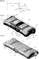
- Weitere Vorteile und Einzelheiten der Erfindung sind in den Patentansprüchen und in der Beschreibung erläutert und in den Figuren dargestellt. Es zeigen:
- Figur 1
- eine Draufsicht einer Schale nach dem Stand der Technik;
- Figur 2a
- eine Draufsicht einer erfindungsgemäßen Schale;
- Figur 2b
- eine Schnittdarstellung S-S aus
Figur 2a ; - Figur 3
- eine perspektivische Ansicht eines Tiefziehwerkzeugs;
- Figur 4
- eine perspektivische Ansicht eines Schalenschalldämpfers.
- Eine erste Schale 1.1 eines Schalenschalldämpfers 1 nach dem Stand der Technik wird gebildet durch Tiefziehen eines Blechstreifens 2, der ausgehend von einem Blechband-Coil rechteckförmig ausgebildet ist. Durch Tiefziehen einer gewünschten Kontur KS der Schale 1.1 mit einer Grundform G, die nach
Fig. 1 kastenförmig, also rechteckförmig mit abgerundeten Ecken ausgebildet ist, wird zunächst ein sogenannter Rohling R erhalten, dessen Rand eine Kontur KR aufweist, die einerseits von der rechteckigen Form des Blechstreifens 2 abweicht und andererseits von der gewünschten kastenförmigen Kontur KS der Schale 1.1 abweicht. Die Kontur KR des Rohlings R wird auch als knochenförmig bezeichnet, da im Bereich der jeweiligen Ecke der verbleibende und zwecks Bildung der Kontur KS bzw. Außenkontur KSa der Schale 1.1 abzuschneidende Rand wesentlich größer ist als in dem Bereich zwischen der jeweiligen Ecke. - Nach
Fig. 2a ist die erfindungsgemäße Kontur KS, also Außenkontur KSa und Innenkontur KSi der Schale 1.1 an die knochenförmige Kontur KR des Rohlings R angepasst. Die Schale 1.1 bzw. Kontur KS weist hierzu eine Grundform G auf, bei der Eckbereiche E1 - E4 über die Breite B und die Länge L hinaus erweitert sind, so dass die Kontur KS zumindest teilweise an die Kontur KR des zu beschneidenden Randbereichs BR des Rohlings R angepasst ist. Somit ergeben sich zwei gegenüberliegenden Längskanten L1, L2 und zwei wiederum gegenüberliegenden Querkanten Q1, Q2, die jeweils über einen Eckbereich E1, E2, E3, E4 miteinander verbunden sind. Zwischen den jeweiligen Eckbereichen E1 bis E4 weist die Kontur KS bzw. die Grundform G eine Taillierung T auf. Im Bereich der jeweiligen Taillierung T ist der Abstand der beiden Längskanten L1, L2 bzw. der beiden Querkanten Q1, Q2 kleiner als eine Länge w1 der Schale 1.1 bzw. eine Breite w2 der Schale 1.1. Mit der Erweiterung des jeweiligen Eckbereichs E1 bis E4 in die Eckzone eines Randbereichs BR des Rohlings R ergeben sich eine Volumenvergrößerung des durch die Schale 1.1 einseitig begrenzten Volumens und eine Verkleinerung des abzuschneidenden Randbereichs BR des Rohlings R. Durch diese Volumenvergrößerung kann die Gesamtweite w2 bzw. die Gesamtweite w1 zwecks Gewährleistung des gleichen Volumens der jeweiligen Schale 1.1 verkleinert werden. - Die hier dargestellte Schale 1.1 weist im Bereich ihrer Längskante L2 eine Ausformung A für eine Ein- bzw. Ausgangskalotte 1.3 nach
Fig. 4 auf. Zwecks Bildung dieser Ausformung A ist im Bereich der Ausformung A eine Einformung E der Tiefe t2 vorgesehen. Die Einformung E ist im Wesentlichen gebildet aus einem Verrundungsradius VR1 und einem daran anschließenden Verbindungsabschnitt VA1. Die Einformung E ist ergänzend zu der Taillierung T vorgesehen. Die Ausformung A erstreckt sich über den vorgenannten Verrundungsradius VR1 und den daran anschließenden Verbindungsabschnitt VA1 sowie einen daran anschließenden Verrundungsradius VR2 über eine Höhe h. Aufgrund der Einformung E steht die Ausformung A im Bereich der Längskante L2 lediglich über eine Tiefe t1 über die knochenförmige Innenkontur KSi der Schale 1.1 hervor. Die Tiefe t1 ist derart gewählt, dass der Blechstreifen 2 allein aufgrund der Ausformung A nicht breiter gewählt werden muss als in dem Fall ohne Ausformung A. Die Tiefe t1 entspricht demnach etwa der Dicke des Randbereichs BS bzw. der Höhe des Verrundungsradius VR2, der an den Verbindungsabschnitt VA1 und den Verrundungsradius VR1 der Ausformung A anschließt. Mithin endet die Ausformung A etwa auf Höhe der Außenkontur KSa. - Die Taillierung T verläuft über etwa 84 % der Länge w1 und 66 % der Breite w2. In einem nicht dargestellten Ausführungsbeispiel kann die Taillierung T auch nur an einem Teil der jeweiligen Längs- bzw. Querkanten L1 bis Q2 vorgesehen sein.
- Nach
Fig. 2b , Schnittdarstellung S-S ausFig. 2a (Teilschnitt rechte Hälfte) weist die Schale 1.1 einen verbleibenden Randbereich BS auf, der nach dem Beschneiden des Randbereichs BR des Rohlings R mit der Außenkontur KR verbleibt. In diesem Randbereich BS wird die Schale 1.1 mit einer korrespondierenden zweiten Schale 1.2 nachFig. 4 verbunden. Dies kann durch Verschweißung oder Umbördelung erfolgen. Letztlich weist der Randbereich BS eine Innenkontur KSi sowie eine Außenkontur KSa auf, die nach AusführungsbeispielFig. 2a ,2b gleich sind. Grundsätzlich ist es auch möglich, dass die Innenkontur KSi von der Außenkontur KSa abweicht. Zwecks Gewährleistung eines erfindungsgemäßen maximalen Volumens ist die erfindungsgemäße Ausprägung der Kontur KS zumindest im Bereich der Innenkontur KSi vorzusehen. Mithin folgt zumindest eine ähnlich große Ausprägung bzw. Erweiterung für die Außenkontur KSa. Die Ausprägung bzw. Erweiterung für die Außenkontur KSa kann auch größer sein als die der Innenkontur KSi. - Ein in
Fig. 3 dargestelltes Tiefziehwerkzeug 3 bzw. Ziehstempel weist ebenfalls eine Außenkontur KW mit einer knochenförmigen Grundform G3 mit vier Eckbereichen E1 - E4 auf. Das Tiefziehwerkzeug 3 weist zudem zwei Formen 3.1, 3.1' zur Bildung einer gewünschten Ausformung A für eine Ein- bzw. Ausgangskalotte 1.3 sowohl im Bereich der Längskante als auch im Bereich der Querkante auf. Die Formen 3.1, 3.1' stehen um eine Tiefe t3, t3' über die Außenkontur KW hervor. Die Tiefe t3, t3' ist derart gewählt, dass die Breite des zur Verfügung stehenden Blechstreifens 2 zur Ausbildung der Ausformung A ausreicht. Zudem ist im Bereich der Form 3.1 ergänzend zu der Taillierung T ein Versatz 3.2, 3.2' vorgesehen ist, wobei der Versatz 3.2, 3.2' relativ zu der Grundform G der Außenkontur Kw um eine Tiefe t4 zurücksteht. Die Form 3.1 steht somit über die Tiefe t3 plus die Tiefe t4 über die Grundform G der Außenkontur Kw hervor. - Nach
Fig. 4 weisen sowohl die erste Schale 1.1 als auch die zweite Schale 1.2 die korrespondierende und gleiche Grundform G bzw. Kontur KS auf, die in den Eckbereichen E1 - E4 nachFig. 2a entsprechend dem in der Regel verbleibenden Randbereich BR bzw. dessen Kontur KR des Rohlings R nach ausgebildet bzw. erweitert sind. Die beiden Schalen 1.1 und 1.2 sind im Randbereich BS miteinander verbunden, so dass sie insgesamt das pro Schale gewährleistete erweiterte Volumen in doppelter Form begrenzen. Die hier zu sehende knochenförmige Ausbildung des Schalenschalldämpfers 1 gewährleistet auch die vorgehend beschriebenen akustischen Vorteile. Darüber hinaus sind im Bereich der jeweiligen Schale Rippen 1.4, 1.4' vorgesehen, die ergänzend das akustische Verhalten bzw. Resonanzverhalten verbessern. Die Rippen 1.4, 1.4' verlaufen etwa parallel zur jeweiligen Querkante. Daneben können diese auch mehrfach vorgesehen sein und alternativ in einem nicht dargestellten Ausführungsbeispiel auch in andere Richtungen, insbesondere parallel zur jeweiligen Längskante, verlaufen. Die Schalen 1.1, 1.2 sind beschnitten, so dass sich die Außenkontur KSa ergibt. Die Ausformung A ist ebenfalls beschnitten, so dass die Tiefe t1 (nicht dargestellt) deutlich kleiner ist als nach dem Ausformen. -
Fig. 5 zeigt die Detailansicht D ausFig. 2a betreffend die Ausformung A mit dem Verrundungsradius VR1 der Einformung E, dem Verrundungsradius VR2, der Ausformung A und dem Verbindungsabschnitt VA, über die die Innenkontur KSi in die Kontur der Ausformung A überführt wird. Die Höhe h der Ausformung A entspricht den beiden Tiefen t1 und t2. Dabei ist die Tiefe t1 das Maß, mit dem die Ausformung A im Bereich der Längskante L2 über die knochenförmige Innenkontur KSi bzw. die Grundform G der Schale 1.1 hervorsteht. Die Tiefe t2 ist das Maß, mit dem die Einformung E relativ zu der Grundform G der Innenkontur KSi des Randbereichs BS der Schale 1.1, 1.2 zurücksteht. -
- 1
- Schalenschalldämpfer
- 1.1
- erste Schale
- 1.2
- zweite Schale
- 1.3
- Ein- oder Ausgangskalotte
- 1.4
- Rippen
- 1.4'
- Rippen
- 2
- Blechstreifen
- 3
- Tiefziehwerkzeug
- 3.1
- Form für Ein- oder Ausgangskalotte
- 3.1'
- Form für Ein- oder Ausgangskalotte
- 3.2
- Versatz
- 3.2'
- Versatz
- A
- Ausformung
- w1
- Länge
- w2
- Breite
- B
- Breite
- BR
- Randbereich
- BS
- Randbereich
- D
- Detailansicht
- E
- Einformung
- E1
- Eckbereich
- E2
- Eckbereich
- E3
- Eckbereich
- E4
- Eckbereich
- G
- Grundform
- G3
- Grundform
- h
- Höhe
- KR
- Kontur Rohling
- KSi
- Innenkontur Schale
- KSa
- Außenkontur Schale
- KW
- Außenkontur Tiefziehwerkzeug
- L
- Länge
- L1
- erste Längskante
- L2
- zweite Längskante
- Q1
- erste Querkante
- Q2
- zweite Querkante
- R
- Schalenrohling
- T
- Taillierung
- t1
- Tiefe
- t2
- Tiefe
- VA
- Verbindungsabschnitt
- VR1
- Verrundungsradius
- VR2
- Verrundungsradius
- w1
- Weite
- w2
- Weite
Claims (4)
- Verfahren zum Ermitteln einer Innen- und/oder Außenkontur KSi, KSa eines Randbereichs BS einer Schale (1.1, 1.2) zum Herstellen eines Schalldämpfers (1) mit folgenden Verfahrensschrittena) Tiefziehen einer Schale (1.1, 1.2) aus einem Blechstreifen (2) mit einem Tiefziehwerkzeug (3) mit kastenförmiger Außenkontur Kw;b) ermitteln der Außenkontur KR des so hergestellten tiefgezogenen Rohlings R;c) erweitern von mindestens einem der Eckbereiche E1-E4 des Tiefziehwerkzeugs (3) derart, dass die Außenkontur Kw und somit die herzustellende Innen- und/oder Außenkontur KSi, KSa an die Außenkontur KR angenähert wird;d) mindestens einmaliges Wiederholen der Verfahrensschritte a) bis c).
- Verfahren zum Ermitteln einer Innen- und/oder Außenkontur KSi, KSa eines Randbereichs BS einer Schale (1.1, 1.2) zum Herstellen eines Schalldämpfers (1) mit folgenden Verfahrensschrittena) Tiefziehen einer Schale (1.1, 1.2) aus einem Blechstreifen (2) mit einem Tiefziehwerkzeug (3) mit einer Außenkontur Kw, wobei die Außenkontur Kw eine Form (3.1) zum Ausbilden einer Ausformung A zwecks Bildung einer Ein- oder Ausgangskalotte (1.3) zum Anschließen eines Abgasrohres aufweist;b) Ermitteln der Tiefe t1, t2 der Ausformung A des so hergestellten tiefgezogenen Rohlings R;c) Optimieren der Tiefe t3, t3' der Form (3.1) der Außenkontur Kw des Tiefziehwerkzeuges (3) und somit der herzustellenden Innen- und/oder Außenkontur KSi, KSa derart, dasszwecks Bildung der Ausformung A die Größe des Blechstreifens (2) nicht größer gewählt werden muss als bei einem Ausbleiben der Ausformung A.
- Verfahren zum Herstellen eines Schalenschalldämpfers (1) für eine Brennkraftmaschine gebildet aus einer ersten Schale (1.1) und mindestens einer zweiten Schale (1.2), die am jeweiligen Randbereich BS verbunden werden, wobei der jeweilige Randbereich BS eine kastenförmige Innenkontur KSi mit vier Eckbereichen E1 - E4 und einer Breite B und eine Länge L sowie eine Außenkontur KSa aufweist und die jeweilige Schale (1.1, 1.2) aus einem Schalenrohling R hergestellt wird, der durch Umformung eines Blechstreifens (2) durch Anwendung eines die Form der Schale (1.1, 1.2) aufweisenden Tiefziehwerkzeugs (3) gebildet wird, wobei der Rohling R nach dem Umformen einen Randbereich BR mit einer äußeren Kontur KR aufweist, und der Randbereich BR beim anschließenden Zuschnitt des Rohlings R zwecks Bildung der Außenkontur KSa des Randbereichs BS der Schale (1.1, 1.2) zumindest teilweise entfernt wird unter Anwendung einer Innen- und/oder Außenkontur KSi, KSa, ermittelt nach dem Verfahren nach Patentanspruch 1, wobeia) die Innenkontur KSi des Randbereichs BS der Schale (1.1, 1.2) ergänzend zu der kastenförmigen Grundform G mit mindestens einem Eckbereich E1 - E4 versehen wird, der über die Breite B und die Länge L der kastenförmigen Grundform G hinaus erweitert ist und somit die Innenkontur KSi an die Kontur KR des zu beschneidenden Randbereichs BR des Rohlings R angepasst wird und/oderb) an der jeweiligen Schale (1.1, 1.2) die Ausformung A zwecks Bildung einer Ein- oder Ausgangskalotte (1.3) zum Anschließen eines Abgasrohres vorgesehen ist, wobei die Ausformung A relativ zu der Grundform G der Innenkontur KSi des Randbereichs BS der Schale (1.1, 1.2) um eine Tiefe t1 hervorsteht, und die Tiefe t1 derart gewählt ist, dass zwecks Bildung der Ausformung A die Größe des Blechstreifens (2) nicht größer gewählt werden muss als bei einem Ausbleiben der Ausformung A.
- Verfahren nach Anspruch 3,
dadurch gekennzeichnet,
dass im Bereich der Ausformung A eine Einformung E vorgesehen wird, die ergänzend zu der Taillierung T vorgesehen ist, wobei die Einformung E relativ zu der Grundform G der Innenkontur KSi des Randbereichs BS der Schale (1.1, 1.2) um eine Tiefe t2 zurücksteht.
Applications Claiming Priority (2)
| Application Number | Priority Date | Filing Date | Title |
|---|---|---|---|
| DE201010020826 DE102010020826B4 (de) | 2010-05-18 | 2010-05-18 | Abgasschalldämpfer für Brennkraftmaschinen und Tiefziehwerkzeug hierfür sowie Verfahren zur Herstellung eines solchen Schalldämpfers |
| PCT/EP2011/057983 WO2011144621A1 (de) | 2010-05-18 | 2011-05-17 | Abgasschalldämpfer für brennkraftmaschinen und tiefziehwerkzeug hierfür |
Publications (2)
| Publication Number | Publication Date |
|---|---|
| EP2571636A1 EP2571636A1 (de) | 2013-03-27 |
| EP2571636B1 true EP2571636B1 (de) | 2018-03-14 |
Family
ID=44626973
Family Applications (1)
| Application Number | Title | Priority Date | Filing Date |
|---|---|---|---|
| EP11724995.3A Not-in-force EP2571636B1 (de) | 2010-05-18 | 2011-05-17 | Verfahren zum herstellen eines abgasschalldämpfers für brennkraftmaschinen |
Country Status (6)
| Country | Link |
|---|---|
| US (1) | US9440276B2 (de) |
| EP (1) | EP2571636B1 (de) |
| CN (1) | CN102985194B (de) |
| BR (1) | BR112012029354A2 (de) |
| DE (1) | DE102010020826B4 (de) |
| WO (1) | WO2011144621A1 (de) |
Families Citing this family (3)
| Publication number | Priority date | Publication date | Assignee | Title |
|---|---|---|---|---|
| EP3431732B1 (de) | 2017-07-21 | 2020-04-22 | Bosal Emission Control Systems NV | Verfahren zur formung eines kragens in einem schalldämpfergehäuse |
| CN108266254A (zh) * | 2018-01-17 | 2018-07-10 | 无锡曙光模具有限公司 | 一种汽车消音半壳及其加工方法 |
| CN117583472B (zh) * | 2023-10-17 | 2024-04-26 | 无锡曙光精密工业有限公司 | 一种半壳冲压成型件的嵌块式冲压模具与工艺 |
Family Cites Families (25)
| Publication number | Priority date | Publication date | Assignee | Title |
|---|---|---|---|---|
| US3263637A (en) * | 1964-12-23 | 1966-08-02 | Darwin S Cox | Method of deep drawing rectangular shapes |
| US3568254A (en) * | 1968-09-19 | 1971-03-09 | Monsanto Co | Apparatus for deep draw molding |
| US3638756A (en) * | 1969-12-30 | 1972-02-01 | United States Steel Corp | Vehicle muffler and method of assembly |
| US4309888A (en) * | 1976-07-22 | 1982-01-12 | Kraftco Corporation | Apparatus for forming a container pan |
| US4909348A (en) * | 1988-01-20 | 1990-03-20 | Ap Parts Manufacturing Company | Stamp formed exhaust muffler with conformal outer shell |
| US4836330A (en) * | 1988-08-03 | 1989-06-06 | Ap Industries, Inc. | Plural chamber stamp formed muffler with single intermediate tube |
| US4865154A (en) * | 1988-09-26 | 1989-09-12 | Tennessee Gas Pipeline Company | Muffler with drain holes |
| US4905791A (en) * | 1989-01-23 | 1990-03-06 | Ap Parts Manufacturing Company | Light weight hybrid exhaust muffler and method of manufacture |
| FR2646207A1 (fr) | 1989-04-25 | 1990-10-26 | Devil | Silencieux modulaire |
| US5004069A (en) * | 1990-01-26 | 1991-04-02 | Ap Parts Manufacturing Company | Stamp formed muffler with transverse baffle tube |
| US5164551A (en) * | 1990-12-03 | 1992-11-17 | Ap Parts Manufacturing Co. | Stamp formed muffler with compound reinforcement pattern for preventing shell ring |
| US5280142A (en) * | 1991-10-18 | 1994-01-18 | Ap Parts Manufacturing Company | Heat shielded exhaust system component |
| US5428194A (en) * | 1993-10-19 | 1995-06-27 | Ap Parts Manufacturing Company | Narrow width stamp formed muffler |
| US5448831A (en) * | 1993-11-08 | 1995-09-12 | Ap Parts Manufacturing Company | Method of manufacturing a stamp formed muffler with hermetically sealed laminated outer shell |
| US5949035A (en) * | 1997-03-24 | 1999-09-07 | Arvin Industries, Inc. | Stamp-formed muffler having a unitary inner cartridge |
| DE19747914A1 (de) * | 1997-10-30 | 1999-05-06 | Stihl Maschf Andreas | Abgasschalldämpfer |
| DE29805455U1 (de) * | 1998-03-26 | 1998-06-04 | Fa. Andreas Stihl, 71336 Waiblingen | Abgasschalldämpfer für den Verbrennungsmotor eines tragbaren Arbeitsgerätes |
| DE19849118B4 (de) | 1998-10-24 | 2012-03-22 | Andreas Stihl Ag & Co. | Abgasschalldämpfer |
| US6931367B2 (en) | 2001-11-29 | 2005-08-16 | Faurecia Exhaust Systems, Inc. | Optimal rib design method for exhaust components |
| DE10239132B4 (de) * | 2002-08-27 | 2012-11-15 | Andreas Stihl Ag & Co | Abgasschalldämpfer |
| DE10243225A1 (de) * | 2002-09-17 | 2004-03-25 | Volkswagen Ag | Schalldämpfer und Verfahren zu seiner Auslegung |
| DE202004000659U1 (de) * | 2004-01-17 | 2004-04-15 | Heinrich Gillet Gmbh | Schalldämpfer für Kraftfahrzeuge mit Verbrennungsmotor |
| EP1895118A1 (de) * | 2006-08-29 | 2008-03-05 | Tecumseh Products Company | Passiver Sekundärluftschalldämpfer |
| KR101063640B1 (ko) * | 2008-06-12 | 2011-09-08 | 현대자동차주식회사 | 차량용 소음기 |
| DE202008016200U1 (de) * | 2008-12-06 | 2009-03-12 | Heinrich Gillet Gmbh | Schalldämpfer für Abgasanlagen |
-
2010
- 2010-05-18 DE DE201010020826 patent/DE102010020826B4/de active Active
-
2011
- 2011-05-17 CN CN201180034173.XA patent/CN102985194B/zh active Active
- 2011-05-17 BR BR112012029354A patent/BR112012029354A2/pt active Search and Examination
- 2011-05-17 EP EP11724995.3A patent/EP2571636B1/de not_active Not-in-force
- 2011-05-17 US US13/697,956 patent/US9440276B2/en not_active Expired - Fee Related
- 2011-05-17 WO PCT/EP2011/057983 patent/WO2011144621A1/de not_active Ceased
Also Published As
| Publication number | Publication date |
|---|---|
| US20130056298A1 (en) | 2013-03-07 |
| EP2571636A1 (de) | 2013-03-27 |
| WO2011144621A1 (de) | 2011-11-24 |
| DE102010020826B4 (de) | 2013-06-06 |
| BR112012029354A2 (pt) | 2017-12-05 |
| CN102985194A (zh) | 2013-03-20 |
| DE102010020826A1 (de) | 2011-11-24 |
| CN102985194B (zh) | 2015-12-09 |
| US9440276B2 (en) | 2016-09-13 |
Similar Documents
| Publication | Publication Date | Title |
|---|---|---|
| DE202016103279U1 (de) | Sechzehneckiges Verstärkungselement für Fahrzeuge | |
| EP2477765B1 (de) | Verfahren zum herstellen eines lenkers für ein fahrzeug | |
| EP3473823B1 (de) | Schalldämpfer mit schalldämpfereinsatz und verfahren zur herstellung eines schalldämpfer mit schalldämpfereinsatz | |
| DE102013113390B4 (de) | Verfahren zur Herstellung einer Pressform für die Massenproduktion einer warmumgeformten, kalten Verkleidung | |
| EP2595771B1 (de) | Verfahren zur herstellung eines kühlkanalkolbens für brennkraftmaschinen und derart hergestellter kolben | |
| DE60209008T2 (de) | Verfahren zur herstellung eines kopfelementes für heizgeräte | |
| EP2032393A1 (de) | Strukturbauteil, insbesondere hitzeschild | |
| DE102016103029B4 (de) | Gehäuse für einen Kraffahrzeugantriebsstrang und Verfahren zu dessen Herstellung | |
| DE102011054866A1 (de) | Verfahren zur Herstellung eines warmumgeformten und pressgehärteten Kraftfahrzeugkarosseriebauteils sowie Kraftfahrzeugkarosseriebauteil | |
| DE102009041524A1 (de) | Plattenwärmetauscher | |
| DE102010020826B4 (de) | Abgasschalldämpfer für Brennkraftmaschinen und Tiefziehwerkzeug hierfür sowie Verfahren zur Herstellung eines solchen Schalldämpfers | |
| DE102009005261A1 (de) | Verfahren zur Herstellung eines komplexen Blechformteils | |
| EP0861975A2 (de) | Abgaskrümmerflansch für eine Brennkraftmaschine | |
| EP3042140A1 (de) | Rohrboden | |
| DE19922046C2 (de) | Verfahren zum Formen einer Kurbelwelle und Verfahren zum Herstellen einer Kurbelwelle | |
| WO2020053135A1 (de) | Abdeckung an einem bauteil einer abgasanlage sowie verfahren zum herstellen eines solchen bauteils mit einer abdeckung | |
| DE2501613A1 (de) | Segmentmatrizen | |
| EP1980728A1 (de) | Tiefziehblechbauteil in Schalenbauweise | |
| EP1771697B1 (de) | Wärmeübertrager, kasten zur aufnahme eines fluids für einen wärmeübertrager sowie verfahren zur herstellung eines derartigen kastens | |
| DE6800650U (de) | Werkzeug zur spanabhebenden bearbeitung eines werkstuecks und vorrichtung zu seiner herstellung. | |
| DE112008001511T5 (de) | Schalldämpfer für eine Auspuffleitung eines Kraftfahrzeugs | |
| EP3586990B1 (de) | Verfahren zur erhöhung der mechanischen stabilität eines randbereichs | |
| WO2012130346A1 (de) | Verbundmaterial mit prägung und mikroperforierung | |
| EP2468432A1 (de) | Verfahren zum Herstellen einer Schaltkulisse, Schaltkulisse sowie Verbrennungsmotor | |
| AT513267B1 (de) | Napfförmiger Körper und Verfahren zu dessen Herstellung |
Legal Events
| Date | Code | Title | Description |
|---|---|---|---|
| PUAI | Public reference made under article 153(3) epc to a published international application that has entered the european phase |
Free format text: ORIGINAL CODE: 0009012 |
|
| 17P | Request for examination filed |
Effective date: 20121217 |
|
| AK | Designated contracting states |
Kind code of ref document: A1 Designated state(s): AL AT BE BG CH CY CZ DE DK EE ES FI FR GB GR HR HU IE IS IT LI LT LU LV MC MK MT NL NO PL PT RO RS SE SI SK SM TR |
|
| DAX | Request for extension of the european patent (deleted) | ||
| 17Q | First examination report despatched |
Effective date: 20131008 |
|
| GRAP | Despatch of communication of intention to grant a patent |
Free format text: ORIGINAL CODE: EPIDOSNIGR1 |
|
| INTG | Intention to grant announced |
Effective date: 20171106 |
|
| GRAS | Grant fee paid |
Free format text: ORIGINAL CODE: EPIDOSNIGR3 |
|
| GRAA | (expected) grant |
Free format text: ORIGINAL CODE: 0009210 |
|
| AK | Designated contracting states |
Kind code of ref document: B1 Designated state(s): AL AT BE BG CH CY CZ DE DK EE ES FI FR GB GR HR HU IE IS IT LI LT LU LV MC MK MT NL NO PL PT RO RS SE SI SK SM TR |
|
| REG | Reference to a national code |
Ref country code: GB Ref legal event code: FG4D Free format text: NOT ENGLISH |
|
| REG | Reference to a national code |
Ref country code: CH Ref legal event code: EP Ref country code: AT Ref legal event code: REF Ref document number: 978351 Country of ref document: AT Kind code of ref document: T Effective date: 20180315 |
|
| REG | Reference to a national code |
Ref country code: IE Ref legal event code: FG4D Free format text: LANGUAGE OF EP DOCUMENT: GERMAN |
|
| REG | Reference to a national code |
Ref country code: DE Ref legal event code: R096 Ref document number: 502011013896 Country of ref document: DE |
|
| REG | Reference to a national code |
Ref country code: NL Ref legal event code: MP Effective date: 20180314 |
|
| REG | Reference to a national code |
Ref country code: LT Ref legal event code: MG4D |
|
| PG25 | Lapsed in a contracting state [announced via postgrant information from national office to epo] |
Ref country code: NO Free format text: LAPSE BECAUSE OF FAILURE TO SUBMIT A TRANSLATION OF THE DESCRIPTION OR TO PAY THE FEE WITHIN THE PRESCRIBED TIME-LIMIT Effective date: 20180614 Ref country code: ES Free format text: LAPSE BECAUSE OF FAILURE TO SUBMIT A TRANSLATION OF THE DESCRIPTION OR TO PAY THE FEE WITHIN THE PRESCRIBED TIME-LIMIT Effective date: 20180314 Ref country code: HR Free format text: LAPSE BECAUSE OF FAILURE TO SUBMIT A TRANSLATION OF THE DESCRIPTION OR TO PAY THE FEE WITHIN THE PRESCRIBED TIME-LIMIT Effective date: 20180314 Ref country code: LT Free format text: LAPSE BECAUSE OF FAILURE TO SUBMIT A TRANSLATION OF THE DESCRIPTION OR TO PAY THE FEE WITHIN THE PRESCRIBED TIME-LIMIT Effective date: 20180314 Ref country code: CY Free format text: LAPSE BECAUSE OF FAILURE TO SUBMIT A TRANSLATION OF THE DESCRIPTION OR TO PAY THE FEE WITHIN THE PRESCRIBED TIME-LIMIT Effective date: 20180314 Ref country code: FI Free format text: LAPSE BECAUSE OF FAILURE TO SUBMIT A TRANSLATION OF THE DESCRIPTION OR TO PAY THE FEE WITHIN THE PRESCRIBED TIME-LIMIT Effective date: 20180314 |
|
| PG25 | Lapsed in a contracting state [announced via postgrant information from national office to epo] |
Ref country code: GR Free format text: LAPSE BECAUSE OF FAILURE TO SUBMIT A TRANSLATION OF THE DESCRIPTION OR TO PAY THE FEE WITHIN THE PRESCRIBED TIME-LIMIT Effective date: 20180615 Ref country code: SE Free format text: LAPSE BECAUSE OF FAILURE TO SUBMIT A TRANSLATION OF THE DESCRIPTION OR TO PAY THE FEE WITHIN THE PRESCRIBED TIME-LIMIT Effective date: 20180314 Ref country code: LV Free format text: LAPSE BECAUSE OF FAILURE TO SUBMIT A TRANSLATION OF THE DESCRIPTION OR TO PAY THE FEE WITHIN THE PRESCRIBED TIME-LIMIT Effective date: 20180314 Ref country code: RS Free format text: LAPSE BECAUSE OF FAILURE TO SUBMIT A TRANSLATION OF THE DESCRIPTION OR TO PAY THE FEE WITHIN THE PRESCRIBED TIME-LIMIT Effective date: 20180314 Ref country code: BG Free format text: LAPSE BECAUSE OF FAILURE TO SUBMIT A TRANSLATION OF THE DESCRIPTION OR TO PAY THE FEE WITHIN THE PRESCRIBED TIME-LIMIT Effective date: 20180614 |
|
| PG25 | Lapsed in a contracting state [announced via postgrant information from national office to epo] |
Ref country code: MT Free format text: LAPSE BECAUSE OF FAILURE TO SUBMIT A TRANSLATION OF THE DESCRIPTION OR TO PAY THE FEE WITHIN THE PRESCRIBED TIME-LIMIT Effective date: 20180314 |
|
| PG25 | Lapsed in a contracting state [announced via postgrant information from national office to epo] |
Ref country code: PL Free format text: LAPSE BECAUSE OF FAILURE TO SUBMIT A TRANSLATION OF THE DESCRIPTION OR TO PAY THE FEE WITHIN THE PRESCRIBED TIME-LIMIT Effective date: 20180314 Ref country code: IT Free format text: LAPSE BECAUSE OF FAILURE TO SUBMIT A TRANSLATION OF THE DESCRIPTION OR TO PAY THE FEE WITHIN THE PRESCRIBED TIME-LIMIT Effective date: 20180314 Ref country code: EE Free format text: LAPSE BECAUSE OF FAILURE TO SUBMIT A TRANSLATION OF THE DESCRIPTION OR TO PAY THE FEE WITHIN THE PRESCRIBED TIME-LIMIT Effective date: 20180314 Ref country code: AL Free format text: LAPSE BECAUSE OF FAILURE TO SUBMIT A TRANSLATION OF THE DESCRIPTION OR TO PAY THE FEE WITHIN THE PRESCRIBED TIME-LIMIT Effective date: 20180314 Ref country code: RO Free format text: LAPSE BECAUSE OF FAILURE TO SUBMIT A TRANSLATION OF THE DESCRIPTION OR TO PAY THE FEE WITHIN THE PRESCRIBED TIME-LIMIT Effective date: 20180314 Ref country code: NL Free format text: LAPSE BECAUSE OF FAILURE TO SUBMIT A TRANSLATION OF THE DESCRIPTION OR TO PAY THE FEE WITHIN THE PRESCRIBED TIME-LIMIT Effective date: 20180314 |
|
| PG25 | Lapsed in a contracting state [announced via postgrant information from national office to epo] |
Ref country code: CZ Free format text: LAPSE BECAUSE OF FAILURE TO SUBMIT A TRANSLATION OF THE DESCRIPTION OR TO PAY THE FEE WITHIN THE PRESCRIBED TIME-LIMIT Effective date: 20180314 Ref country code: SK Free format text: LAPSE BECAUSE OF FAILURE TO SUBMIT A TRANSLATION OF THE DESCRIPTION OR TO PAY THE FEE WITHIN THE PRESCRIBED TIME-LIMIT Effective date: 20180314 Ref country code: SM Free format text: LAPSE BECAUSE OF FAILURE TO SUBMIT A TRANSLATION OF THE DESCRIPTION OR TO PAY THE FEE WITHIN THE PRESCRIBED TIME-LIMIT Effective date: 20180314 |
|
| REG | Reference to a national code |
Ref country code: CH Ref legal event code: PL |
|
| REG | Reference to a national code |
Ref country code: DE Ref legal event code: R097 Ref document number: 502011013896 Country of ref document: DE |
|
| PG25 | Lapsed in a contracting state [announced via postgrant information from national office to epo] |
Ref country code: PT Free format text: LAPSE BECAUSE OF FAILURE TO SUBMIT A TRANSLATION OF THE DESCRIPTION OR TO PAY THE FEE WITHIN THE PRESCRIBED TIME-LIMIT Effective date: 20180716 |
|
| PLBE | No opposition filed within time limit |
Free format text: ORIGINAL CODE: 0009261 |
|
| STAA | Information on the status of an ep patent application or granted ep patent |
Free format text: STATUS: NO OPPOSITION FILED WITHIN TIME LIMIT |
|
| REG | Reference to a national code |
Ref country code: BE Ref legal event code: MM Effective date: 20180531 |
|
| PG25 | Lapsed in a contracting state [announced via postgrant information from national office to epo] |
Ref country code: DK Free format text: LAPSE BECAUSE OF FAILURE TO SUBMIT A TRANSLATION OF THE DESCRIPTION OR TO PAY THE FEE WITHIN THE PRESCRIBED TIME-LIMIT Effective date: 20180314 Ref country code: MC Free format text: LAPSE BECAUSE OF FAILURE TO SUBMIT A TRANSLATION OF THE DESCRIPTION OR TO PAY THE FEE WITHIN THE PRESCRIBED TIME-LIMIT Effective date: 20180314 |
|
| 26N | No opposition filed |
Effective date: 20181217 |
|
| REG | Reference to a national code |
Ref country code: IE Ref legal event code: MM4A |
|
| GBPC | Gb: european patent ceased through non-payment of renewal fee |
Effective date: 20180614 |
|
| PG25 | Lapsed in a contracting state [announced via postgrant information from national office to epo] |
Ref country code: LI Free format text: LAPSE BECAUSE OF NON-PAYMENT OF DUE FEES Effective date: 20180531 Ref country code: CH Free format text: LAPSE BECAUSE OF NON-PAYMENT OF DUE FEES Effective date: 20180531 Ref country code: SI Free format text: LAPSE BECAUSE OF FAILURE TO SUBMIT A TRANSLATION OF THE DESCRIPTION OR TO PAY THE FEE WITHIN THE PRESCRIBED TIME-LIMIT Effective date: 20180314 |
|
| PG25 | Lapsed in a contracting state [announced via postgrant information from national office to epo] |
Ref country code: LU Free format text: LAPSE BECAUSE OF NON-PAYMENT OF DUE FEES Effective date: 20180517 |
|
| PG25 | Lapsed in a contracting state [announced via postgrant information from national office to epo] |
Ref country code: IE Free format text: LAPSE BECAUSE OF NON-PAYMENT OF DUE FEES Effective date: 20180517 Ref country code: GB Free format text: LAPSE BECAUSE OF NON-PAYMENT OF DUE FEES Effective date: 20180614 Ref country code: FR Free format text: LAPSE BECAUSE OF NON-PAYMENT OF DUE FEES Effective date: 20180531 |
|
| PG25 | Lapsed in a contracting state [announced via postgrant information from national office to epo] |
Ref country code: BE Free format text: LAPSE BECAUSE OF NON-PAYMENT OF DUE FEES Effective date: 20180531 |
|
| REG | Reference to a national code |
Ref country code: AT Ref legal event code: MM01 Ref document number: 978351 Country of ref document: AT Kind code of ref document: T Effective date: 20180517 |
|
| PGFP | Annual fee paid to national office [announced via postgrant information from national office to epo] |
Ref country code: DE Payment date: 20190418 Year of fee payment: 9 |
|
| PG25 | Lapsed in a contracting state [announced via postgrant information from national office to epo] |
Ref country code: AT Free format text: LAPSE BECAUSE OF NON-PAYMENT OF DUE FEES Effective date: 20180517 |
|
| PG25 | Lapsed in a contracting state [announced via postgrant information from national office to epo] |
Ref country code: TR Free format text: LAPSE BECAUSE OF FAILURE TO SUBMIT A TRANSLATION OF THE DESCRIPTION OR TO PAY THE FEE WITHIN THE PRESCRIBED TIME-LIMIT Effective date: 20180314 |
|
| PG25 | Lapsed in a contracting state [announced via postgrant information from national office to epo] |
Ref country code: HU Free format text: LAPSE BECAUSE OF FAILURE TO SUBMIT A TRANSLATION OF THE DESCRIPTION OR TO PAY THE FEE WITHIN THE PRESCRIBED TIME-LIMIT; INVALID AB INITIO Effective date: 20110517 |
|
| PG25 | Lapsed in a contracting state [announced via postgrant information from national office to epo] |
Ref country code: MK Free format text: LAPSE BECAUSE OF NON-PAYMENT OF DUE FEES Effective date: 20180314 |
|
| PG25 | Lapsed in a contracting state [announced via postgrant information from national office to epo] |
Ref country code: IS Free format text: LAPSE BECAUSE OF FAILURE TO SUBMIT A TRANSLATION OF THE DESCRIPTION OR TO PAY THE FEE WITHIN THE PRESCRIBED TIME-LIMIT Effective date: 20180714 |
|
| REG | Reference to a national code |
Ref country code: DE Ref legal event code: R119 Ref document number: 502011013896 Country of ref document: DE |
|
| PG25 | Lapsed in a contracting state [announced via postgrant information from national office to epo] |
Ref country code: DE Free format text: LAPSE BECAUSE OF NON-PAYMENT OF DUE FEES Effective date: 20201201 |
|
| P01 | Opt-out of the competence of the unified patent court (upc) registered |
Effective date: 20230528 |