EP2569095B1 - Spender - Google Patents
Spender Download PDFInfo
- Publication number
- EP2569095B1 EP2569095B1 EP11721460.1A EP11721460A EP2569095B1 EP 2569095 B1 EP2569095 B1 EP 2569095B1 EP 11721460 A EP11721460 A EP 11721460A EP 2569095 B1 EP2569095 B1 EP 2569095B1
- Authority
- EP
- European Patent Office
- Prior art keywords
- mouth opening
- dispenser
- dispenser head
- retracted state
- region
- Prior art date
- Legal status (The legal status is an assumption and is not a legal conclusion. Google has not performed a legal analysis and makes no representation as to the accuracy of the status listed.)
- Active
Links
Images


Classifications
-
- B—PERFORMING OPERATIONS; TRANSPORTING
- B05—SPRAYING OR ATOMISING IN GENERAL; APPLYING FLUENT MATERIALS TO SURFACES, IN GENERAL
- B05B—SPRAYING APPARATUS; ATOMISING APPARATUS; NOZZLES
- B05B15/00—Details of spraying plant or spraying apparatus not otherwise provided for; Accessories
- B05B15/50—Arrangements for cleaning; Arrangements for preventing deposits, drying-out or blockage; Arrangements for detecting improper discharge caused by the presence of foreign matter
-
- B—PERFORMING OPERATIONS; TRANSPORTING
- B05—SPRAYING OR ATOMISING IN GENERAL; APPLYING FLUENT MATERIALS TO SURFACES, IN GENERAL
- B05B—SPRAYING APPARATUS; ATOMISING APPARATUS; NOZZLES
- B05B11/00—Single-unit hand-held apparatus in which flow of contents is produced by the muscular force of the operator at the moment of use
- B05B11/01—Single-unit hand-held apparatus in which flow of contents is produced by the muscular force of the operator at the moment of use characterised by the means producing the flow
- B05B11/10—Pump arrangements for transferring the contents from the container to a pump chamber by a sucking effect and forcing the contents out through the dispensing nozzle
- B05B11/1042—Components or details
- B05B11/1059—Means for locking a pump or its actuation means in a fixed position
- B05B11/106—Means for locking a pump or its actuation means in a fixed position in a retracted position, e.g. in an end-of-dispensing-stroke position
Definitions
- a dispenser in which the dispensing head in the region of the mouth and opposite in cross section encloses a line appearing surface with a vertical acute angle and in the retracted state with a similarly formed on the housing wall bearing surface in abutment.
- the seal can only be achieved by the accuracy of fit of the adjacent surfaces.
- the mouth opening or a wall area surrounding the mouth opening moves vertically onto the abutment wall.
- Both the abutment wall as well as the mouth opening or the board wall surrounding the mouth opening are preferably formed obliquely in cross section in cross section. They are vertically overlapping. In plant condition, a sealing surface support can thus be achieved.
- the wall area forming the mouth opening on the dispenser head need not necessarily be in the retracted state in sealing engagement with the wall of the housing wall. It can also be a bead-like surrounding the mouth opening wall - only - in Appendix.
- the housing wall can be the same, which also the plant wall formed. In this respect, it is preferably a circular ring-shaped housing wall surrounding the dispensing head as a whole.
- the pressure system is given by a displacement of the dispensing head in the retracted state achieved as a result of an excess in the region of the mouth opening.
- the dispenser head is, for example, as it were tilted at least in this section of its retraction area.
- An area F which in the in Fig. 2 Cross section shown touches the bead 5, includes with a vertical V an acute angle ⁇ .
- the angle ⁇ preferably corresponds to more than 0.1 ° up to, for example, 10 °. Also all intermediate values, in particular in 1/10 ° -steps, on the one hand to delimit the said range boundaries from below and / or above, alternatively or additionally but also with regard to the disclosure of one or more singular values in the said range, are hereby included in the disclosure.
- a mating surface 9 Diametrically opposite to the contact surface 6 of the dispenser head 2 in the retracted state in a pressure system on a mating surface 9 in this area - also - formed housing 3.
- the mating surface 9 is also provided in the region of a U-shaped region of the housing 3. If, as preferred, the system is given in the cantilevered leg 10 of the U-shaped wall, also a certain suspension effect is achieved.
Landscapes
- Closures For Containers (AREA)
- Containers And Packaging Bodies Having A Special Means To Remove Contents (AREA)
- Dental Tools And Instruments Or Auxiliary Dental Instruments (AREA)
Description
- Die Erfindung betrifft einen Spender nach den Merkmalen des Oberbegriffs des Anspruches 1.
- Zum Stand der Technik ist zunächst auf die
WO2009/127651 A1 zu verweisen. - Aus der
CH 582101 A5 - Aus der
US 2009/0120963 A1 ist ein Spender bekannt, bei welchem der Spendekopf im Bereich der Mündung und gegenüberliegend in einem Querschnitt eine als Linie erscheinende Fläche mit einer Vertikalen einen spitzen Winkel einschließt und im eingefahrenen Zustand mit einer gleichartig an der Gehäusewand ausgebildeten Anlagefläche in Anlage ist. Die Dichtung lässt sich nur durch die Passgenauigkeit der aneinanderliegenden Flächen erreichen. - Eine vergleichbare Gestaltung ist auch aus der
US-A-3884390 bekannt. - Ausgehend von dem zuletzt genannten Stand der Technik beschäftigt sich die Erfindung mit der Aufgabenstellung, den Spender hinsichtlich einer günstigeren Abdichtung im eingefahrenen Zustand des Spenderkopfes vorteilhaft auszubilden.
- Diese Aufgabe ist beim Gegenstand des Anspruches 1 gelöst, wobei darauf abgestellt ist, dass der Spenderkopf bzw. der Teil des Spenderkopfes gegenüberliegend zu der Fläche im eingefahrenen Zustand in Druckanlage zu einer Innenfläche einer dort im eingefahrenen Zustand in Überdeckung befindlichen Gehäusewand ist und dass die Druckanlage durch eine zufolge eines Übermaßes im Bereich der Mündungsöffnung erreichten Verschiebung des Spenderkopfes gegeben ist.
- Beim Einfahren des Spenderkopfes oder des Spenderkopfteils fährt die Mündungsöffnung bzw. ein die Mündungsöffnung umgebender Wandungsbereich vertikal auf die Anlagewand. Sowohl die Anlagewand wie auch die Mündungsöffnung oder die die Mündungsöffnung umgebende Vorstandswand sind im Querschnitt bevorzugt gleich gerichtet schräg ausgebildet. Sie sind vertikal in Überdeckung. Im Anlagezustand lässt sich so eine Dichtflächenauflage erreichen.
- Der bevorzugt im Grundriss jedenfalls im Bereich der Mündungsöffnung kreisförmig gestaltete Spenderkopf oder das Spenderkopfteil ist weiter bevorzugt, wenn auch abweichend hiervon eine kalottenartige Gestaltung möglich ist, ebenflächig gestaltet.
- Hierbei muss nicht notwendig unmittelbar der Wandungsbereich, der die Mündungsöffnung am Spenderkopf ausbildet, in dichtender Anlage an der Anlagewand der Gehäusewand im eingefahrenen Zustand sein. Es kann auch eine beispielsweise wulstartig die Mündungsöffnung umgebende Wand - nur - in Anlage sein.
- Dadurch, dass der Teil des Spenderkopfes gegenüberliegend zu der Fläche im eingefahrenen Zustand in Druckanlage zu einer Innenfläche der dort im eingefahrenen Zustand in Überdeckung befindlichen Gehäusewand ist, wird zugleich auch eine Abdicht- Druckanlage im Bereich der Mündungsöffnung erreicht. Die Gehäusewand kann die gleiche sein, welche auch die Anlagewand ausbildet. Bevorzugt handelt es sich insofern um eine kreis- ringförmige, den Spenderkopf insgesamt umgebende Gehäusewand. Die Druckanlage ist durch eine zufolge eines Übermaßes im Bereich der Mündungsöffnung erreichten Verschiebung des Spenderkopfes im eingefahrenen Zustand gegeben.
- Der Spenderkopf wird bspw. gleichsam jedenfalls in diesem Abschnitt seines Einfahrbereiches verkippt.
- Nachstehend ist die Erfindung des Weiteren anhand der beigefügten Zeichnung, die jedoch lediglich ein Ausführungsbeispiel darstellt, erläutert. Hierbei zeigt:
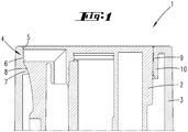
- Fig. 1:
- ein Querschnitt durch den Spender im Bereich des Spenderkopfes, im eingefahrenen Zustand;
- Fig. 2:
- eine Darstellung gemäß
Figur 1 im ausgefahrenen Zustand; - Fig. 3:
- eine perspektivische Ansicht des Spenderkopfes im Bereich der Ausgabemündung;
- Fig. 4:
- eine Ansicht von oben des Spenders bei eingefahrenem Spenderkopf.
- Fig. 5:
- eine perspektivische Ansicht der Gehäusewandung, bei herausgenommenem Spenderkopf;
- Dargestellt und beschrieben ist ein Spender 1 mit einem Spenderkopf 2 und einer den Spenderkopf 2 im eingefahrenen Zustand gemäß
Figur 1 umgebenden Gehäusewandung 3. - Der Spenderkopf 2 ist Teil einer Pumpkammer, wie sich dies in weiterer Einzelheit aus der bereits einleitend genannten
WO 2009/127651 A1 ergibt. Zur weiteren Erläuterung wird auch hierauf Bezug genommen. - Der Spenderkopf 2 weist eine Mündungsöffnung 4 auf, die beim Ausführungsbeispiel von einer Dichtwulst 5 umgeben ist. Die Dichtwulst 5 liegt im eingefahrenen Zustand gemäß
Figur 1 an einer innenseitig der Gehäusewandung 3 ausgebildeten Anlagefläche 6. Ein Überfahren nach unten ist weiterhin durch einen unterhalb der Anlagefläche 6 ausgebildeten Haltevorsprung 7 gehindert, auf dem beim Überfahren eine Unterseitenfläche 8 des Spenderkopfes 2, ausgebildet unterhalb der Mündungsöffnung 4, stoßen würde. - Eine Fläche F, welche in dem in
Fig. 2 gezeigten Querschnitt den Wulst 5 berührt, schließt mit einer Vertikalen V einen spitzen Winkel α ein. Der Winkel α entspricht bevorzugt mehr als 0,1° bis hin zu bspw. 10°. Auch alle Zwischen-Werte, insbesondere in 1/10°-Schritten, einerseits zur Eingrenzung der genannten Bereichsgrenzen von unten und/oder oben, alternativ oder ergänzend aber auch im Hinblick auf die Offenbarung eines oder mehrerer singulärer Werte in dem genannten Bereich, sind hiermit in die Offenbarung eingeschlossen. - Die Anlagefläche 6 ist wie beim Ausführungsbeispiel bevorzugt gleich gestaltet zu der Fläche F ausgebildet. Beide Flächen können im Grundriss kreisabschnittsförmig oder kalottenförmig verlaufen. Sie können aber auch geradlinig verlaufen.
- Während der Winkel α sich nach unten öffnet, verläuft sichtlich die Anlagefläche 6 mit einem sich nach oben öffnenden Winkel bezogen auf eine Vertikale V.
- Diametral gegenüberliegend zu der Anlagefläche 6 ist der Spenderkopf 2 im eingefahrenen Zustand in Druckanlage an einer Gegenfläche 9 der in diesem Bereich - auch - ausgebildeten Gehäusewandung 3. Die Gegenfläche 9 ist zudem im Bereich eines U-förmig gestalteten Bereiches der Gehäusewandung 3 vorgesehen. Wenn, wie bevorzugt, die Anlage in dem freitragenden Schenkel 10 der U-förmig gestalteten Wandung gegeben ist, ist zudem ein gewisser Federungseffekt erreicht.
- Die Anlage an der Gegenfläche 9 kann durch das Herunterfahren des Spenderkopfes 2 bewirkt sein, indem ein gewisses Übermaß, d.h. bei vertikaler Projizierung aus der ausgefahrenen Stellung von
Fig. 2 in die eingefahrene Stellung gemäßFig. 1 sich bezüglich der Fläche F und der Gegenfläche 6 eine Überschneidung ergeben würde. Sie kann aber auch durch eine entsprechende Wulstausbildung an der Gegenfläche 9 erreicht sein. - Das Verfahren des Spenderkopfes 2, und damit insbesondere auch das Herunterfahren, ist bevorzugt durch eine Kulissenführung bewirkt. Hierzu kann in einer feststehenden Außenhülse, wie in der eingangs genannten
WO 2009/ 127651 A1 beschrieben, worauf hierzu insbesondere nochmals Bezug genommen wird, auch insbesondere zur Einbeziehung dieser hier angesprochenen Offenbarung in vorliegender Anmeldung, auch zum Zwecke Merkmalen dieser vorbekannten Anmeldung in Ansprüche vorliegender Anmeldung aufzunehmen, ein Kulissenweg ausgebildet sein, in dem ein am Spenderkopf ausgebildeter Kulissenstein läuft. Dieser Kulissenweg kann sich im Einzelnen weiter bevorzugt aus einem Schrägabschnitt, einem unteren Halteabschnitt und einem oberen Halteabschnitt zusammensetzen. Im vorliegenden Zusammenhang ist insbesondere der untere Halteabschnitt von Bedeutung, denn hiermit lässt sich eine selbsttätige nicht öffnende verspannende Dichtanlage des eingefahrenen Spenderkopfes, nämlich Dichtanlage bezüglich der Spendermündung oder eines umgebenden Wulstes an der Gehäusewandung, wie vorstehend beschrieben, günstig erreichen. - Alternativ oder ergänzend kann diese verspannende Festlegung auch durch eine Verrastung beispielsweise erreicht sein.
- Weiter bevorzugt wird durch die angesprochene Gestaltung, beispielsweise durch die Wulstausbildung, auch ein gewisses Verkippen des Spenderkopfes 2 im eingefahrenen Zustand erreicht. Darüber hinaus können aber auch beidseitig entsprechende Überschneidungen bzw. ein Wulst ausgebildet sein, so dass sich bei streng vertikaler Bewegung die genannte Einklemmung ohne Weiteres ergibt.
- Im Ausführungsbeispiel ist noch bevorzugt vorgesehen, wie dies die
Figuren 4 und5 insbesondere erkennen lassen, dass die Gegenfläche 9 durch versetzt zu einer diametralen Gegenüberlage bzgl. der Mündungsöffnung 4 durch Aussparungen 11 gegenüber dem weiteren, hier mit kreisförmigem Grundriss gebildeten Wandungsverlauf gesondert ist. Dies lässt günstig zusätzlich die gezielte Anlage (Fig. 4 zeigt den ausgefahrenen Zustand) erreichen. - Die Mündungswulst 5 könnte prinzipiell auch aus einem Weichkunststoff bestehen, etwa im Zwei-Komponenten-Spritzverfahren aufgebracht, während der Spenderkopf 2 im Übrigen bevorzugt aus Hartkunststoff besteht. Beim Ausführungsbeispiel besteht jedoch auch der Mündungswulst 5 aus einem Hartkunststoff. Die genannte Druckanlage lässt hier die ausreichend günstige Abdichtung ohne Weiteres auch bei zusammenwirkenden Hartkunststoffteilen erreichen. Auch die Gehäusewandung 3 besteht bevorzugt aus einem Hartkunststoff. Grundsätzlich könnte aber auch die genannte Anlagefläche 6 der Gehäusewandung 3 aus einem Weichkunststoff bestehen, etwa auch hier im Zwei-Komponenten-Spritzverfahren aufgebracht.
Claims (3)
- Spender (1) zur Ausgabe flüssiger oder pastöser Massen mit einem eine Mündungsöffnung (4) aufweisenden Spenderkopf (2), wobei jedenfalls ein die Mündungsöffnung (4) aufweisender Teil des Spenderkopfes (2) bzgl. einer umgebenden Gehäusewandung (3) aus- und einfahrbar ist und eine die Mündungsöffnung (4) oder einen Stirnflächenbereich einer umgebend zu der Mündungsöffnung (4) ausgebildeten Vorstandswandung berührende Fläche (F) in einem Querschnitt, in welchem die Fläche (F) als Linie erscheint, mit einer Vertikalen (V) einen spitzen Winkel (α) einschließt und im eingefahrenen Zustand dieser Bereich in Berührung ist mit einer gleichartig an der Gehäusewand (3) zugewandt der Mündungsöffnung (4) oder dem Stirnflächenbereich ausgebildeten Anlagefläche (6) ist, dadurch gekennzeichnet, dass der Spendekopf (2) bzw. der Teil des Spendekopfes (2) gegenüberliegend zu der Fläche (F) im eingefahrenen Zustand in Druckanlage zu einer Innenfläche einer dort im eingefahrenen Zustand in Überdeckung befindlichen Gehäusewand (3) ist und dass die Druckanlage durch eine zufolge eines Übermaßes im Bereich der Mündungsöffnung (4) erreichten Verschiebung des Spenderkopfes (2) gegeben ist.
- Spender nach Anspruch 1, dadurch gekennzeichnet, dass die Gehäusewand (3) im Bereich der Druckanlage U-förmig gestaltet ist.
- Spender nach einem der vorhergehenden Ansprüche, dadurch gekennzeichnet, dass die Mündungsöffnung (4) von einem Dichtwulst (5) umgeben ist.
Priority Applications (1)
| Application Number | Priority Date | Filing Date | Title |
|---|---|---|---|
| PL11721460T PL2569095T3 (pl) | 2010-05-11 | 2011-05-11 | Dozownik |
Applications Claiming Priority (2)
| Application Number | Priority Date | Filing Date | Title |
|---|---|---|---|
| DE102010016886A DE102010016886A1 (de) | 2010-05-11 | 2010-05-11 | Spender |
| PCT/EP2011/057572 WO2011141491A1 (de) | 2010-05-11 | 2011-05-11 | Spender |
Publications (2)
| Publication Number | Publication Date |
|---|---|
| EP2569095A1 EP2569095A1 (de) | 2013-03-20 |
| EP2569095B1 true EP2569095B1 (de) | 2017-11-01 |
Family
ID=44357981
Family Applications (1)
| Application Number | Title | Priority Date | Filing Date |
|---|---|---|---|
| EP11721460.1A Active EP2569095B1 (de) | 2010-05-11 | 2011-05-11 | Spender |
Country Status (9)
| Country | Link |
|---|---|
| US (1) | US8727188B2 (de) |
| EP (1) | EP2569095B1 (de) |
| CN (1) | CN102985189B (de) |
| BR (1) | BR112012028777B1 (de) |
| CA (1) | CA2798882C (de) |
| DE (1) | DE102010016886A1 (de) |
| ES (1) | ES2646667T3 (de) |
| PL (1) | PL2569095T3 (de) |
| WO (1) | WO2011141491A1 (de) |
Families Citing this family (2)
| Publication number | Priority date | Publication date | Assignee | Title |
|---|---|---|---|---|
| DE102010036352A1 (de) * | 2010-07-12 | 2012-01-12 | Rpc Bramlage Gmbh | Spender zur Ausgabe flüssiger bis pastöser Massen |
| US10472138B2 (en) | 2017-10-12 | 2019-11-12 | Donny Smith | Systems and methods for a device with an internal vented nozzle |
Citations (2)
| Publication number | Priority date | Publication date | Assignee | Title |
|---|---|---|---|---|
| US3884390A (en) * | 1973-11-02 | 1975-05-20 | Polytop Corp | Push-pull closure with probe to prevent clogging |
| US20090120963A1 (en) * | 2007-11-12 | 2009-05-14 | Taesung Industrial Co., Ltd. | Cosmetic receptacle |
Family Cites Families (14)
| Publication number | Priority date | Publication date | Assignee | Title |
|---|---|---|---|---|
| US2790582A (en) * | 1954-12-20 | 1957-04-30 | Halpern Israel Alfred | Pouring spout |
| US2919057A (en) * | 1957-03-18 | 1959-12-29 | Halpern Israel Alfred | Container closure and pouring spout |
| US3733010A (en) * | 1971-04-30 | 1973-05-15 | Ciba Geigy Corp | Air pressure operated dispenser |
| CH582102A5 (en) * | 1972-05-02 | 1976-11-30 | Ciba Geigy Ag | Aerosol distributor - with built-in air compressor |
| US4408700A (en) * | 1981-05-28 | 1983-10-11 | Owens-Illinois, Inc. | Multi-part dispensing closure having a frangible connecting web |
| US4779774A (en) * | 1986-11-17 | 1988-10-25 | Simone Morel | Telescopic capsule for tubes or flasks |
| FR2690419A1 (fr) * | 1992-04-23 | 1993-10-29 | Emballages Conseils Etudes | Capsule distributrice pour produits liquides ou pâteux. |
| FR2706867B1 (de) * | 1993-06-22 | 1995-09-15 | Geiger Sarl | |
| US5890655A (en) * | 1997-01-06 | 1999-04-06 | The Procter & Gamble Company | Fan spray nozzles having elastomeric dome-shaped tips |
| US5961001A (en) * | 1998-03-30 | 1999-10-05 | Liqui-Box Corporation | Venting liquid dispensing spout for closed container |
| US6364178B1 (en) * | 2000-07-11 | 2002-04-02 | Joseph R. Paczonay | Fluid control and dispenser apparatus |
| US7780098B2 (en) * | 2006-07-11 | 2010-08-24 | Meadwestvaco Calmar, Inc. | Fan spray pattern indexing nozzle for a trigger sprayer |
| US8820665B2 (en) * | 2007-09-25 | 2014-09-02 | S.C. Johnson & Son, Inc. | Fluid dispensing nozzle |
| JP5419963B2 (ja) | 2008-04-15 | 2014-02-19 | アールピーシー ブラムラゲ ゲーエムベーハー | ディスペンサ |
-
2010
- 2010-05-11 DE DE102010016886A patent/DE102010016886A1/de not_active Withdrawn
-
2011
- 2011-05-11 PL PL11721460T patent/PL2569095T3/pl unknown
- 2011-05-11 EP EP11721460.1A patent/EP2569095B1/de active Active
- 2011-05-11 CN CN201180034316.7A patent/CN102985189B/zh active Active
- 2011-05-11 CA CA2798882A patent/CA2798882C/en active Active
- 2011-05-11 BR BR112012028777-0A patent/BR112012028777B1/pt not_active IP Right Cessation
- 2011-05-11 ES ES11721460.1T patent/ES2646667T3/es active Active
- 2011-05-11 WO PCT/EP2011/057572 patent/WO2011141491A1/de not_active Ceased
- 2011-05-11 US US13/697,165 patent/US8727188B2/en not_active Expired - Fee Related
Patent Citations (2)
| Publication number | Priority date | Publication date | Assignee | Title |
|---|---|---|---|---|
| US3884390A (en) * | 1973-11-02 | 1975-05-20 | Polytop Corp | Push-pull closure with probe to prevent clogging |
| US20090120963A1 (en) * | 2007-11-12 | 2009-05-14 | Taesung Industrial Co., Ltd. | Cosmetic receptacle |
Also Published As
| Publication number | Publication date |
|---|---|
| BR112012028777A2 (pt) | 2016-07-19 |
| US8727188B2 (en) | 2014-05-20 |
| BR112012028777B1 (pt) | 2020-12-08 |
| CN102985189B (zh) | 2016-10-05 |
| WO2011141491A1 (de) | 2011-11-17 |
| ES2646667T3 (es) | 2017-12-14 |
| US20130056503A1 (en) | 2013-03-07 |
| PL2569095T3 (pl) | 2018-02-28 |
| CN102985189A (zh) | 2013-03-20 |
| DE102010016886A1 (de) | 2011-11-17 |
| EP2569095A1 (de) | 2013-03-20 |
| CA2798882C (en) | 2018-05-22 |
| CA2798882A1 (en) | 2011-11-17 |
Similar Documents
| Publication | Publication Date | Title |
|---|---|---|
| EP2593237B1 (de) | Spender mit drehsicherung | |
| DE69635938T2 (de) | Zerstäuberpumpe für Flüssigkeiten | |
| EP3140211B1 (de) | Zumisch-verschlussvorrichtung für einen behälter | |
| EP1272073B1 (de) | Dampfdruck-kochtopf | |
| DE102004060236A1 (de) | Kappe für einen Aerosolbehälter oder einen Sprühbehälter | |
| EP0347546B1 (de) | Spender für Pasten od. dgl. Medien | |
| DE3151892A1 (de) | Handpumpe zur druckfoerderung von fluessigkeiten und/oder dickfluessigen substanzen aus einem behaelter | |
| EP2509718A1 (de) | Kartuschenkolben | |
| EP3352911B1 (de) | Spender für flüssige bis pastöse massen | |
| DE7916575U1 (de) | Flaschenverschluss | |
| DE102014200867A1 (de) | Spender für Flüssigkeiten | |
| EP3268544B1 (de) | Sanitäres umschaltventil sowie baugruppe mit einem solchen umschaltventil | |
| EP3352910B1 (de) | Spender für flüssige bis pastöse massen | |
| DE3832852A1 (de) | Automatische spruehdose | |
| DE3404672A1 (de) | Abgabepumpe | |
| EP2614011B1 (de) | Verschlussstopfen für pharmazeutische anwendungen | |
| DE1934397A1 (de) | Ventilanordnung fuer Aerosolspruehbehaelter | |
| DE602004001587T2 (de) | Spender für einzelportionskosmetikmuster | |
| DE19915829B4 (de) | Kartusche und Vorrichtung zum Aufbereiten von Flüssigkeiten | |
| DE2141626C3 (de) | Ventilvorrichtung für Aerosolbehälter | |
| EP2569095A1 (de) | Spender | |
| EP3018068A1 (de) | Verschluss, insbesondere kunststoffverschluss für ein behältnis | |
| WO2013120609A1 (de) | Dichtelement, vorzugsweise dichtring | |
| EP0481250B1 (de) | Kartusche zum Einsetzen in Spender | |
| EP2864219B1 (de) | Von einer kappe gehaltene kippbetätigung für einen schaumspender |
Legal Events
| Date | Code | Title | Description |
|---|---|---|---|
| PUAI | Public reference made under article 153(3) epc to a published international application that has entered the european phase |
Free format text: ORIGINAL CODE: 0009012 |
|
| 17P | Request for examination filed |
Effective date: 20121203 |
|
| AK | Designated contracting states |
Kind code of ref document: A1 Designated state(s): AL AT BE BG CH CY CZ DE DK EE ES FI FR GB GR HR HU IE IS IT LI LT LU LV MC MK MT NL NO PL PT RO RS SE SI SK SM TR |
|
| DAX | Request for extension of the european patent (deleted) | ||
| 17Q | First examination report despatched |
Effective date: 20140121 |
|
| GRAP | Despatch of communication of intention to grant a patent |
Free format text: ORIGINAL CODE: EPIDOSNIGR1 |
|
| INTG | Intention to grant announced |
Effective date: 20170518 |
|
| GRAS | Grant fee paid |
Free format text: ORIGINAL CODE: EPIDOSNIGR3 |
|
| GRAA | (expected) grant |
Free format text: ORIGINAL CODE: 0009210 |
|
| AK | Designated contracting states |
Kind code of ref document: B1 Designated state(s): AL AT BE BG CH CY CZ DE DK EE ES FI FR GB GR HR HU IE IS IT LI LT LU LV MC MK MT NL NO PL PT RO RS SE SI SK SM TR |
|
| REG | Reference to a national code |
Ref country code: GB Ref legal event code: FG4D Free format text: NOT ENGLISH |
|
| REG | Reference to a national code |
Ref country code: CH Ref legal event code: EP Ref country code: AT Ref legal event code: REF Ref document number: 941533 Country of ref document: AT Kind code of ref document: T Effective date: 20171115 |
|
| REG | Reference to a national code |
Ref country code: IE Ref legal event code: FG4D Free format text: LANGUAGE OF EP DOCUMENT: GERMAN |
|
| REG | Reference to a national code |
Ref country code: ES Ref legal event code: FG2A Ref document number: 2646667 Country of ref document: ES Kind code of ref document: T3 Effective date: 20171214 Ref country code: DE Ref legal event code: R096 Ref document number: 502011013229 Country of ref document: DE |
|
| REG | Reference to a national code |
Ref country code: NL Ref legal event code: MP Effective date: 20171101 |
|
| REG | Reference to a national code |
Ref country code: LT Ref legal event code: MG4D |
|
| PG25 | Lapsed in a contracting state [announced via postgrant information from national office to epo] |
Ref country code: SE Free format text: LAPSE BECAUSE OF FAILURE TO SUBMIT A TRANSLATION OF THE DESCRIPTION OR TO PAY THE FEE WITHIN THE PRESCRIBED TIME-LIMIT Effective date: 20171101 Ref country code: LT Free format text: LAPSE BECAUSE OF FAILURE TO SUBMIT A TRANSLATION OF THE DESCRIPTION OR TO PAY THE FEE WITHIN THE PRESCRIBED TIME-LIMIT Effective date: 20171101 Ref country code: NO Free format text: LAPSE BECAUSE OF FAILURE TO SUBMIT A TRANSLATION OF THE DESCRIPTION OR TO PAY THE FEE WITHIN THE PRESCRIBED TIME-LIMIT Effective date: 20180201 Ref country code: NL Free format text: LAPSE BECAUSE OF FAILURE TO SUBMIT A TRANSLATION OF THE DESCRIPTION OR TO PAY THE FEE WITHIN THE PRESCRIBED TIME-LIMIT Effective date: 20171101 Ref country code: FI Free format text: LAPSE BECAUSE OF FAILURE TO SUBMIT A TRANSLATION OF THE DESCRIPTION OR TO PAY THE FEE WITHIN THE PRESCRIBED TIME-LIMIT Effective date: 20171101 |
|
| REG | Reference to a national code |
Ref country code: FR Ref legal event code: PLFP Year of fee payment: 8 |
|
| PG25 | Lapsed in a contracting state [announced via postgrant information from national office to epo] |
Ref country code: GR Free format text: LAPSE BECAUSE OF FAILURE TO SUBMIT A TRANSLATION OF THE DESCRIPTION OR TO PAY THE FEE WITHIN THE PRESCRIBED TIME-LIMIT Effective date: 20180202 Ref country code: RS Free format text: LAPSE BECAUSE OF FAILURE TO SUBMIT A TRANSLATION OF THE DESCRIPTION OR TO PAY THE FEE WITHIN THE PRESCRIBED TIME-LIMIT Effective date: 20171101 Ref country code: LV Free format text: LAPSE BECAUSE OF FAILURE TO SUBMIT A TRANSLATION OF THE DESCRIPTION OR TO PAY THE FEE WITHIN THE PRESCRIBED TIME-LIMIT Effective date: 20171101 Ref country code: IS Free format text: LAPSE BECAUSE OF FAILURE TO SUBMIT A TRANSLATION OF THE DESCRIPTION OR TO PAY THE FEE WITHIN THE PRESCRIBED TIME-LIMIT Effective date: 20180301 Ref country code: BG Free format text: LAPSE BECAUSE OF FAILURE TO SUBMIT A TRANSLATION OF THE DESCRIPTION OR TO PAY THE FEE WITHIN THE PRESCRIBED TIME-LIMIT Effective date: 20180201 Ref country code: HR Free format text: LAPSE BECAUSE OF FAILURE TO SUBMIT A TRANSLATION OF THE DESCRIPTION OR TO PAY THE FEE WITHIN THE PRESCRIBED TIME-LIMIT Effective date: 20171101 |
|
| PG25 | Lapsed in a contracting state [announced via postgrant information from national office to epo] |
Ref country code: EE Free format text: LAPSE BECAUSE OF FAILURE TO SUBMIT A TRANSLATION OF THE DESCRIPTION OR TO PAY THE FEE WITHIN THE PRESCRIBED TIME-LIMIT Effective date: 20171101 Ref country code: DK Free format text: LAPSE BECAUSE OF FAILURE TO SUBMIT A TRANSLATION OF THE DESCRIPTION OR TO PAY THE FEE WITHIN THE PRESCRIBED TIME-LIMIT Effective date: 20171101 Ref country code: SK Free format text: LAPSE BECAUSE OF FAILURE TO SUBMIT A TRANSLATION OF THE DESCRIPTION OR TO PAY THE FEE WITHIN THE PRESCRIBED TIME-LIMIT Effective date: 20171101 Ref country code: CZ Free format text: LAPSE BECAUSE OF FAILURE TO SUBMIT A TRANSLATION OF THE DESCRIPTION OR TO PAY THE FEE WITHIN THE PRESCRIBED TIME-LIMIT Effective date: 20171101 Ref country code: CY Free format text: LAPSE BECAUSE OF FAILURE TO SUBMIT A TRANSLATION OF THE DESCRIPTION OR TO PAY THE FEE WITHIN THE PRESCRIBED TIME-LIMIT Effective date: 20171101 |
|
| REG | Reference to a national code |
Ref country code: DE Ref legal event code: R097 Ref document number: 502011013229 Country of ref document: DE |
|
| PG25 | Lapsed in a contracting state [announced via postgrant information from national office to epo] |
Ref country code: SM Free format text: LAPSE BECAUSE OF FAILURE TO SUBMIT A TRANSLATION OF THE DESCRIPTION OR TO PAY THE FEE WITHIN THE PRESCRIBED TIME-LIMIT Effective date: 20171101 Ref country code: IT Free format text: LAPSE BECAUSE OF FAILURE TO SUBMIT A TRANSLATION OF THE DESCRIPTION OR TO PAY THE FEE WITHIN THE PRESCRIBED TIME-LIMIT Effective date: 20171101 Ref country code: RO Free format text: LAPSE BECAUSE OF FAILURE TO SUBMIT A TRANSLATION OF THE DESCRIPTION OR TO PAY THE FEE WITHIN THE PRESCRIBED TIME-LIMIT Effective date: 20171101 |
|
| PLBE | No opposition filed within time limit |
Free format text: ORIGINAL CODE: 0009261 |
|
| STAA | Information on the status of an ep patent application or granted ep patent |
Free format text: STATUS: NO OPPOSITION FILED WITHIN TIME LIMIT |
|
| PG25 | Lapsed in a contracting state [announced via postgrant information from national office to epo] |
Ref country code: MT Free format text: LAPSE BECAUSE OF FAILURE TO SUBMIT A TRANSLATION OF THE DESCRIPTION OR TO PAY THE FEE WITHIN THE PRESCRIBED TIME-LIMIT Effective date: 20171101 |
|
| 26N | No opposition filed |
Effective date: 20180802 |
|
| PG25 | Lapsed in a contracting state [announced via postgrant information from national office to epo] |
Ref country code: SI Free format text: LAPSE BECAUSE OF FAILURE TO SUBMIT A TRANSLATION OF THE DESCRIPTION OR TO PAY THE FEE WITHIN THE PRESCRIBED TIME-LIMIT Effective date: 20171101 |
|
| REG | Reference to a national code |
Ref country code: CH Ref legal event code: PL |
|
| REG | Reference to a national code |
Ref country code: BE Ref legal event code: MM Effective date: 20180531 |
|
| PG25 | Lapsed in a contracting state [announced via postgrant information from national office to epo] |
Ref country code: MC Free format text: LAPSE BECAUSE OF FAILURE TO SUBMIT A TRANSLATION OF THE DESCRIPTION OR TO PAY THE FEE WITHIN THE PRESCRIBED TIME-LIMIT Effective date: 20171101 |
|
| REG | Reference to a national code |
Ref country code: IE Ref legal event code: MM4A |
|
| PG25 | Lapsed in a contracting state [announced via postgrant information from national office to epo] |
Ref country code: LI Free format text: LAPSE BECAUSE OF NON-PAYMENT OF DUE FEES Effective date: 20180531 Ref country code: CH Free format text: LAPSE BECAUSE OF NON-PAYMENT OF DUE FEES Effective date: 20180531 |
|
| PG25 | Lapsed in a contracting state [announced via postgrant information from national office to epo] |
Ref country code: LU Free format text: LAPSE BECAUSE OF NON-PAYMENT OF DUE FEES Effective date: 20180511 |
|
| PG25 | Lapsed in a contracting state [announced via postgrant information from national office to epo] |
Ref country code: IE Free format text: LAPSE BECAUSE OF NON-PAYMENT OF DUE FEES Effective date: 20180511 |
|
| PG25 | Lapsed in a contracting state [announced via postgrant information from national office to epo] |
Ref country code: BE Free format text: LAPSE BECAUSE OF NON-PAYMENT OF DUE FEES Effective date: 20180531 |
|
| REG | Reference to a national code |
Ref country code: AT Ref legal event code: MM01 Ref document number: 941533 Country of ref document: AT Kind code of ref document: T Effective date: 20180511 |
|
| PG25 | Lapsed in a contracting state [announced via postgrant information from national office to epo] |
Ref country code: AT Free format text: LAPSE BECAUSE OF NON-PAYMENT OF DUE FEES Effective date: 20180511 |
|
| PG25 | Lapsed in a contracting state [announced via postgrant information from national office to epo] |
Ref country code: TR Free format text: LAPSE BECAUSE OF FAILURE TO SUBMIT A TRANSLATION OF THE DESCRIPTION OR TO PAY THE FEE WITHIN THE PRESCRIBED TIME-LIMIT Effective date: 20171101 |
|
| PG25 | Lapsed in a contracting state [announced via postgrant information from national office to epo] |
Ref country code: HU Free format text: LAPSE BECAUSE OF FAILURE TO SUBMIT A TRANSLATION OF THE DESCRIPTION OR TO PAY THE FEE WITHIN THE PRESCRIBED TIME-LIMIT; INVALID AB INITIO Effective date: 20110511 Ref country code: PT Free format text: LAPSE BECAUSE OF FAILURE TO SUBMIT A TRANSLATION OF THE DESCRIPTION OR TO PAY THE FEE WITHIN THE PRESCRIBED TIME-LIMIT Effective date: 20171101 |
|
| PG25 | Lapsed in a contracting state [announced via postgrant information from national office to epo] |
Ref country code: MK Free format text: LAPSE BECAUSE OF NON-PAYMENT OF DUE FEES Effective date: 20171101 |
|
| PG25 | Lapsed in a contracting state [announced via postgrant information from national office to epo] |
Ref country code: AL Free format text: LAPSE BECAUSE OF FAILURE TO SUBMIT A TRANSLATION OF THE DESCRIPTION OR TO PAY THE FEE WITHIN THE PRESCRIBED TIME-LIMIT Effective date: 20171101 |
|
| P01 | Opt-out of the competence of the unified patent court (upc) registered |
Effective date: 20230523 |
|
| PGFP | Annual fee paid to national office [announced via postgrant information from national office to epo] |
Ref country code: GB Payment date: 20240521 Year of fee payment: 14 |
|
| PGFP | Annual fee paid to national office [announced via postgrant information from national office to epo] |
Ref country code: DE Payment date: 20240529 Year of fee payment: 14 |
|
| PGFP | Annual fee paid to national office [announced via postgrant information from national office to epo] |
Ref country code: ES Payment date: 20240610 Year of fee payment: 14 |
|
| PGFP | Annual fee paid to national office [announced via postgrant information from national office to epo] |
Ref country code: FR Payment date: 20240527 Year of fee payment: 14 |
|
| PGFP | Annual fee paid to national office [announced via postgrant information from national office to epo] |
Ref country code: PL Payment date: 20250505 Year of fee payment: 15 |
|
| REG | Reference to a national code |
Ref country code: DE Ref legal event code: R119 Ref document number: 502011013229 Country of ref document: DE |
|
| GBPC | Gb: european patent ceased through non-payment of renewal fee |
Effective date: 20250511 |
|
| PG25 | Lapsed in a contracting state [announced via postgrant information from national office to epo] |
Ref country code: GB Free format text: LAPSE BECAUSE OF NON-PAYMENT OF DUE FEES Effective date: 20250511 |
|
| PG25 | Lapsed in a contracting state [announced via postgrant information from national office to epo] |
Ref country code: DE Free format text: LAPSE BECAUSE OF NON-PAYMENT OF DUE FEES Effective date: 20251202 |
|
| PG25 | Lapsed in a contracting state [announced via postgrant information from national office to epo] |
Ref country code: FR Free format text: LAPSE BECAUSE OF NON-PAYMENT OF DUE FEES Effective date: 20250531 |
|
| REG | Reference to a national code |
Ref country code: ES Ref legal event code: FD2A Effective date: 20260629 |
|
| PG25 | Lapsed in a contracting state [announced via postgrant information from national office to epo] |
Ref country code: ES Free format text: LAPSE BECAUSE OF NON-PAYMENT OF DUE FEES Effective date: 20250512 |