EP2568253B1 - Verfahren und system zur messung von strukturiertem licht - Google Patents
Verfahren und system zur messung von strukturiertem licht Download PDFInfo
- Publication number
- EP2568253B1 EP2568253B1 EP10850965.4A EP10850965A EP2568253B1 EP 2568253 B1 EP2568253 B1 EP 2568253B1 EP 10850965 A EP10850965 A EP 10850965A EP 2568253 B1 EP2568253 B1 EP 2568253B1
- Authority
- EP
- European Patent Office
- Prior art keywords
- camera
- matching
- laser light
- light spot
- image position
- Prior art date
- Legal status (The legal status is an assumption and is not a legal conclusion. Google has not performed a legal analysis and makes no representation as to the accuracy of the status listed.)
- Active
Links
- 238000000034 method Methods 0.000 title claims description 81
- 238000013507 mapping Methods 0.000 claims description 27
- 238000004364 calculation method Methods 0.000 claims description 7
- 238000003384 imaging method Methods 0.000 claims description 6
- 230000006870 function Effects 0.000 claims description 3
- 238000009826 distribution Methods 0.000 description 10
- 238000005259 measurement Methods 0.000 description 9
- 239000011159 matrix material Substances 0.000 description 8
- 238000010586 diagram Methods 0.000 description 7
- 238000004422 calculation algorithm Methods 0.000 description 3
- 239000003550 marker Substances 0.000 description 3
- 230000003287 optical effect Effects 0.000 description 3
- 230000000007 visual effect Effects 0.000 description 2
- 239000012141 concentrate Substances 0.000 description 1
- 230000003247 decreasing effect Effects 0.000 description 1
- 230000007547 defect Effects 0.000 description 1
- 238000006073 displacement reaction Methods 0.000 description 1
- 230000000694 effects Effects 0.000 description 1
- 238000005516 engineering process Methods 0.000 description 1
- 238000005286 illumination Methods 0.000 description 1
- 238000002372 labelling Methods 0.000 description 1
- 230000003068 static effect Effects 0.000 description 1
- 238000007619 statistical method Methods 0.000 description 1
Images

Classifications
-
- G—PHYSICS
- G01—MEASURING; TESTING
- G01B—MEASURING LENGTH, THICKNESS OR SIMILAR LINEAR DIMENSIONS; MEASURING ANGLES; MEASURING AREAS; MEASURING IRREGULARITIES OF SURFACES OR CONTOURS
- G01B11/00—Measuring arrangements characterised by the use of optical techniques
- G01B11/24—Measuring arrangements characterised by the use of optical techniques for measuring contours or curvatures
- G01B11/25—Measuring arrangements characterised by the use of optical techniques for measuring contours or curvatures by projecting a pattern, e.g. one or more lines, moiré fringes on the object
- G01B11/2545—Measuring arrangements characterised by the use of optical techniques for measuring contours or curvatures by projecting a pattern, e.g. one or more lines, moiré fringes on the object with one projection direction and several detection directions, e.g. stereo
-
- G—PHYSICS
- G06—COMPUTING; CALCULATING OR COUNTING
- G06T—IMAGE DATA PROCESSING OR GENERATION, IN GENERAL
- G06T7/00—Image analysis
- G06T7/50—Depth or shape recovery
- G06T7/521—Depth or shape recovery from laser ranging, e.g. using interferometry; from the projection of structured light
-
- G—PHYSICS
- G06—COMPUTING; CALCULATING OR COUNTING
- G06T—IMAGE DATA PROCESSING OR GENERATION, IN GENERAL
- G06T2207/00—Indexing scheme for image analysis or image enhancement
- G06T2207/10—Image acquisition modality
- G06T2207/10004—Still image; Photographic image
- G06T2207/10012—Stereo images
Definitions
- the present application relates to a structured-light based measuring method and a structured-light based measuring system employing such a method, and particularly to a structured-light based measuring method and a structured-light based measuring system employing such a method with a high measurement precision.
- a structured-light based measuring system For a structured-light based measuring system, if a light beam spot and its corresponding coordinate Z are known, the coordinate of a cross point of the light beam on the surface of an object may be obtained.
- light beams of the structured-light are designed in such a way that the image distribution of a light beam of the structured-light does not overlap that of a neighboring beam of the structured-light within a camera, and the respective image positions are recorded for various depths (i.e. the coordinates Z).
- An interpolating method may be used for determining 3D coordinates of the known image point.
- an existing structured-light based measuring system for the purpose of ensuring that the image distributions of any two light beams at different depths do not overlap with each other, it is necessary to concentrate the image distribution of each light beam, that is, a small image displacement corresponds to a large physical depth difference, which results in a low measuring precision.
- WO 2004/011876 discloses a stereoscopic optical scanner which includes a marker generator.
- a plurality of marker generators may be disposed along a circumference of an object in order to project the optical markers on the surface of the entire object.
- the pattern projector projects predetermined patterns so that 3D scan data of the object can be obtained. Namely, space-encoded beams are projected on the surface of the object. That is, each marker is identified by relative position information of markers computed by processors based on 3D scans.
- WO 2008/120457 discloses a 3D image measurement apparatus of non-static estimating movement state of object with a captured full-illumination reflected image and a reflected pattern image.
- US 5,852,672 describes a 3D measuring system with six cameras placed around the measured object and that uses laser projection, where each of the sets of stereo pair of images is processed by the computer to generate three dimensional coordinates of the object surface at grid points, where the processing software establishes a correspondence of grid points seen from two perspectives i.e. cameras.
- a long-coherence length laser is divided into a pair of beams by a splitter.
- a pair of spatial filters directs the resulting pair of beam fans to cross. Then maximum intensity and minimum intensity at an intersect are used to determine information of an object.
- US 2005/018209 A1 discloses an optical 3D digitizing method with an enlarged non-ambiguity zone, comprising: controllably projecting a fringe pattern having a shiftable position over a target area; capturing images obtained by high depth resolution sensing and low depth resolution sensing from respective measurement fields at least partially overlapping each other over the target area; determining absolute pixel 3D positions in the images obtained by low depth resolution sensing and high depth resolution sensing as a function of relations depending on the fringe pattern in the captured images and correspondence between the absolute pixel 3D positions in the images; extracting chromatic texture from the captured images; and building a complete textured 3D model from the absolute pixel 3D positions and the chromatic texture.
- US 5,061,062 discloses a focus spot size controller for a variable depth triangulation ranging system.
- the ranging system includes an apparatus for emitting light beam to be focused onto an object, a light sensitive apparatus, a lens apparatus for imaging reflected light onto said light sensitive apparatus, and an apparatus for calculating system geometry and range from signals received from the light sensitive apparatus.
- the technical problem to be addressed by the present invention is to provide a structured-light based measuring method and a structured-light based measuring system using such a method as defined by the independent claims 1 and 6.
- the present invention provide a technical solution that includes a structured-light based measuring method including:
- the demarcation database is obtained by a demarcating process including: demarcating the first mapping relationship between an image position of each laser light spot within the first camera and the sequence number as well as the low-precision depth of the laser light spot, demarcating the second mapping relationship between an image position of each laser light spot within the second camera and the sequence number as well as the high-precision depth of the laser light spot, and storing the demarcated first and second mapping relationships in a memory to form the demarcation database for the use by the matching process and the calculating process.
- a position of a laser output port relative the first camera is adjusted to prevent image positions of any two laser light spots within the first camera from overlapping with each other.
- the distance between the second camera and the laser output port is larger than the distance between the first camera and the laser output port.
- the demarcating process and the matching process are performed in a condition that image positions at different depths of the same laser light spot are surrounded by a geometric region.
- the precise position of the laser light spot is obtained by an interpolating method applied on the image position in the second camera and the high-precision depth during the calculating process.
- conducting matching according to the image position of the laser light spot within the first camera and the respective candidates of matching point within the second camera during the matching process includes: searching for a reference matching pair according to a luminance difference of images of the laser light spot; and determining the optimal matching point using the reference matching pair.
- the method further includes: conducting a 3D reconstruction of the candidates of matching point, to obtain a depth of each of the candidate of matching point; and conducting initial selection among the candidates of matching point according to the depths of the candidates of matching point.
- a structured-light based measuring system including a processing system, an imaging system and a projecting system, where the imaging system includes a first camera and a second camera, the projecting system includes a laser generator for generating laser light, and the processing system includes a matching module and a calculating module, the matching module is adapted for obtaining a sequence number and a low-precision depth of a laser light spot based on an image position of the laser light spot within a first camera according to a first mapping relationship in a demarcation database, searching for image positions of the laser light spot within a second camera according to the sequence number and the low-precision depth of the laser light spot to obtain candidates of matching point, and conducting matching according to the image position of the laser light spot within the first camera and the respective candidates of matching point within the second camera, to obtain a result of the matching; and the calculating module is adapted for obtaining an image position within the second camera that matches with the image position within the first camera according to the result of the matching, and determining a precise position of the laser
- the demarcation database is obtained by a demarcating module through a demarcating process including: demarcating the first mapping relationship between an image position of each laser light spot within the first camera and the sequence number as well as the low-precision depth of the laser light spot, demarcating the second mapping relationship between an image position of each laser light spot within the second camera and the sequence number as well as the high-precision depth of the laser light spot, and storing the demarcated first and second mapping relationships in a memory to form the demarcation database for the use by the matching process and the calculating process.
- a position of a laser output port relative the first camera is adjusted to prevent image positions of any two laser light spots within the first camera from overlapping with each other.
- the distance between the second camera and the laser output port is larger than the distance between the first camera and the laser output port.
- functions of the demarcating module and the matching module are implemented in a condition that image positions at different depths of the same laser light spot are surrounded by a geometric region.
- the precise position of the laser light spot is obtained by an interpolating method applied on the image position in the second camera and the high-precision depth during the calculating process.
- conducting matching according to the image position of the laser light spot within the first camera and the respective candidates of matching point within the second camera by the matching module includes: searching for a reference matching pair according to a luminance difference of images of the laser light spot; and determining the optimal matching point using the reference matching pair.
- the matching module is further adapted for conducting a 3D reconstruction of the candidates of matching point, to obtain a depth of each of the candidate of matching point; and conducting initial selection among the candidates of matching point according to the depths of the candidates of matching point.
- the structured-light based measuring method and a structured-light based measuring system using such a method of the present invention are advantageous in that the measurement precision of the system is greatly improved by adding the second camera for fine measurement to the existing structured-light measuring system.
- a demarcation database is established through the demarcating process, so that the structured-light measuring process is simplified.
- the image positions of any two laser light spots within the first camera do not overlap with each other, so that the accuracy of the mapping relationship between the image position and the depth of each laser light spot (that is formed on the measured object) within the first camera is ensured during the demarcating process.
- the distance between the second camera and the laser output port is larger than the distance between the first camera and the laser output port, so that a mapping relationship between the image position and the depth that is provided by the second camera is more precise than that provided by the first camera.
- a geometric region is used for surrounding image positions at various depths of the same laser light spot in order to conduct the demarcating process and the matching process, and the matching speed may be accelerated.
- the precise position of the laser light spot is obtained by an interpolating method applied on the sequence of the image position in the second camera and the depth, so that multiple precise depths of the measured objected may be obtained.
- the matching is conducted according to the image position of the laser light spot within the first camera and the respective candidates of matching point within the second camera during the matching process, so that the matching result may be obtained more easily, simply and quickly.
- a structured-light based measuring method of the invention includes a matching process and a calculating process, in which the used demarcation database is obtained through a demarcating process.
- a first mapping relationship between an image position of each laser light spot within a first camera 21 and the sequence number as well as a low-precision depth (i.e. scene depth) of the laser light spot is determined.
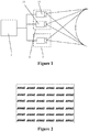
- an image position of a laser light spot i at a depth Z i j within the first camera 21 is denoted by ( u i j , v i j ) , and the image distributions of any two laser light spots are prevented from overlapping with each other by adjusting the position of the laser output port 31 (as shown in Figure 6 ) with respect to the first camera 21, as shown in the schematic image in Figure 2 .
- Each of the point sets that are not overlapped and are separated in Figure 2 represents an image distribution of one laser light spot at various depths, and each point in the point set represents an image position of a laser light spot corresponding to the point set at a different depth.
- data recorded for the laser light spot i may be denoted by u 1 i v 1 i z 1 i ⁇ u j i v j i z j i ⁇ u N i i v N i i z N i i , here, N i denotes the number of the demarcated images of the laser light spot i at various depths.
- the point set may be surrounded by a regular geometric region in a shape such as a rectangle and an ellipse.
- the data recorded for the laser light spot i is denoted by Param i u 1 i v 1 i z 1 i ⁇ u j i v j i z j i ⁇ u N i i v N i i z N i i
- N i denotes the number of the demarcated images of the laser light spot i at various depths
- Param i denotes a parameter for the region surrounding the point set, which may be the maximum and minimum horizontal and vertical coordinates of rectangle corners for a rectangular region surrounding the point set, or a center point and major and minor axes of an ellipse for an elliptic region surrounding the point set.
- Figure 3 shows schematic division by rectangular surrounding regions.
- a second mapping relationship between an image position of each laser light spot within a second camera 22 and the sequence number as well as a high-precision depth of the laser light spot is determined.
- an image position of a laser light spot i at a depth Z i j within the second camera 22 is denoted by ( u i j , v i j )
- data recorded for the laser light spot i may be denoted by u 1 i v 1 i z 1 i ⁇ u j i v j i z j i ⁇ u N i i v N i i z N i i , here, N i denotes the number of experimental data of the laser light spot i.
- the image positions of two laser light spots might be overlapped, as schematically shown in Figure 4 .
- the point set may be surrounded by a regular geometric region in a regular shape such as a rectangle and an ellipse.
- the data recorded for the laser light spot i is denoted by Param i u 1 i v 1 i z 1 i ⁇ u j i v j i z j i ⁇ u N i i v N i i z N i i
- N i denotes the number of the experimental data of the laser light spot i
- Param i denotes a parameter for the region surrounding the point set, which may be the maximum and minimum horizontal and vertical coordinates of rectangle corners for a rectangular region surrounding the point set, or a center point and major and minor axes of an ellipse for an elliptic region surrounding the point set.
- Figure 5 shows schematic rectangular surrounding regions.
- the image position sequence within the first camera 21 is denoted by u 1 A v 1 A , ⁇ , u i A v i A , ⁇ , u M A v M A
- the image position sequence within the second camera 22 is denoted by u 1 B v 1 B , ⁇ , u j B v j B , ⁇ , u N B v N B .
- Any possible point among the image position sequence within the second camera 22 that matches the image position u i A v i A within the first camera 21 may be determined by the following steps (1), (2) and (3).
- the sequence number and a low-precision depth of the laser light spot are determined according to an image position within the first camera 21 and the recorded table (e.g. the demarcation database) in the first camera 21.
- the sequence number and a low-precision depth of a laser light spot corresponding to such image position may be determined directly (i.e. based on the first mapping relationship).
- the determining of the sequence number and the low-precision depth may be as follows depending on different data in the recorded table obtained during the demarcation.
- step (2) according to the obtained sequence number of the laser light spot and the sequence number of the image position of the laser light spot within the first camera 21, the image distribution of the laser light spot within the second camera 22 is searched out and candidates of matching point are obtained based on the image distribution.
- the demarcated point data obtained from the demarcation data of the first camera 21 may be denoted by u T Index v T Index z T Index .
- the obtained sequence of the demarcated image distribution of the laser light spot within the second camera 22 may be denoted by Param index u 1 index v 1 index z 1 index ⁇ u j index v j index z j index ⁇ u N index index v N index index index z N index index .
- Candidates of demarcated point are searched out from the sequence of the demarcated image distribution of a laser light spot Index within the second camera 22 by a manner of obtaining a demarcated point within a range having a center z T Index , i.e. z T Index ⁇ d ⁇ z j Index ⁇ z T Index + d .
- d denotes a matching search range that is defined manually.
- any image point having satisfying similarity is determined from the image points u 1 B v 1 B , ⁇ , u j B v j B , ⁇ , u N B v N B in the second camera 22 by a method (A) or (B) below depending on the data of the recorded table obtained during the demarcation.
- any of the image points u 1 B v 1 B , ⁇ , u j B v j B , ⁇ , u N B v N B that falls within the surrounding region Param Index is determined.
- the surrounding region Param Index defined by ⁇ min_ u Index , max_ u Index ,min_ v Index ,max_ v Index ⁇ shall meet conditions of min _ u Index ⁇ u j B ⁇ max _ u Index and min _ v Index ⁇ v j B ⁇ max _ v Index .
- the matching process is completed based on the known sequence of image positions u 1 A v 1 A , ⁇ , u i A v i A , ⁇ , u M A v M A within the first camera 21 and the candidates of matching point therefor within the second camera 22.
- an object at the present stage is to find the best matching point for the point u i A v i A among the candidates of matching point, e.g. by below steps (A), (B), (C) and (D).
- Steps (A) and (B) above relate to the coarse selection and may be selected for performing as desired.
- the following general assignment algorithm may be used for implementing the matching between the sequence u 1 A v 1 A , ⁇ , u i A v i A , ⁇ , u M A v M A of known image positions in the first camera 21 and the respective candidates of matching point in the second camera 22.
- x ij is an MxN matrix.
- the matching process above involves a relatively large amount of calculation due to the assumption that any of p i and q j might form a matching pair, which is a Non-deterministic Polynomial (N-P) problem.
- N-P Non-deterministic Polynomial
- Many optimized algorithms were proposed for the N-P problem, but involve a calculation amount which is dramatically increased along with the increase of the size of the similarity matrix C.
- C A 0 0 B
- the similarity matrix C is calculated in the term of similarity of properties such as an image area, an image major axis, and an image minor axis, and information such as the epipolar constraint of a stereo vision system which is known to those skilled in the art may be taken into consideration.
- the matrixes A and B are calculated through known methods such as the Hungary algorithm and the Branch-and-Bound Method.
- the precise position of the laser light spot is determined according to the result of the matching.
- the image position of the light spot in the second camera 22 is obtained, and a precise position of the light spot may be obtained through an interpolating method according to the second mapping relationship between the image position of a light spot within the second camera 22 and the sequence number as well as the high-precision depth of the light spot.
- the distance between the second camera 22 and the laser output port 31 is larger than that between the first camera 21 and the laser output port 31, and the laser output port 31 is at a side of the first camera 21 that is opposite to the second camera 22, or arranged between the first and second camera 21 and 22.
- the laser output port is located at a side of the first camera 21 that is opposite to the second camera 22, and the distance between the second camera 22 and the laser output port 31 is larger than the distance between the first camera 21 and the laser output port 31.
- the laser output port 31 is arranged between the first and second camera 21 and 22, and the distance between the second camera 22 and the laser output port 31 is larger than the distance between the first camera 21 and the laser output port 31.
- a mapping relationship between the image position and the depth provided by the second camera 22 is more precise than that provided by the first camera 21, and the precision of the second camera 22 may be adjusted as desired actually.
- the position of the laser output port 31 may be adjusted as desired as long as the distance between the second camera 22 and the laser output port 31 is larger than the distance between the first camera 21 and the laser output port 31.
Claims (10)
- Ein Verfahren zur Messung basierend auf strukturiertem Licht mit:einem Abgrenzungsprozess, der das Abgrenzen einer ersten Zuordnungsbeziehung zwischen einer Bildposition jedes Laserlichtflecks, die mit Sequenznummern innerhalb einer ersten Kamera (21) nummeriert sind und der Sequenznummer sowie einer wenig genauen Tiefe des Laserlichtflecks, das Abgrenzen einer zweiten Zuordnungsbeziehung zwischen einer Bildposition jedes Laserlichtflecks innerhalb einer zweiten Kamera (22) und der Sequenznummer sowie einer hochgenauen Tiefe des Laserlichtflecks und Speichern der abgegrenzten ersten und zweiten Zuordnungsbeziehungen in einem Speicher, um eine Abgrenzungsdatenbank für die Verwendung durch einen Abgleichprozess und einen Berechnungsprozess zu bilden, umfasst;dem Abgleichprozess, der das Erhalten der Sequenznummer und der wenig genauen Tiefe des Laserlichtflecks basierend auf einer Bildposition des Laserlichtflecks innerhalb der ersten Kamera (21) gemäß der ersten Zuordnungsbeziehung in der Abgrenzungsdatenbank, das Suchen nach Bildpositionen des Laserlichtflecks innerhalb der zweiten Kamera (22) gemäß der Sequenznummer und der wenig genauen Tiefe des Laserlichtflecks, um Kandidaten für einen Abgleichpunkt zu erhalten und Durchführen eines Abgleichs gemäß der Bildposition des Laserlichtpunkts innerhalb der ersten Kamera (21) und den jeweiligen Kandidaten des Abgleichpunkts innerhalb der zweiten Kamera (22), um ein Ergebnis des Abgleichs zu erhalten umfasst; unddem Berechnungsprozess, der das Erhalten einer Bildposition innerhalb der zweiten Kamera (22), die mit der Bildposition innerhalb der ersten Kamera (21), gemäß dem Ergebnis des Abgleichs übereinstimmt und dem Bestimmen der genauen Position des Laserlichtflecks gemäß der zweiten Zuordnungsbeziehung in der Abgrenzungsdatenbank umfasst;wobei das Durchführen des Abgleichs gemäß der Bildposition des Laserlichtflecks innerhalb der ersten Kamera (21) und derjeweiligen Kandidaten des Abgleichpunkts innerhalb der zweiten Kamera (22) während des Abgleichprozesses umfasst:Suchen nach einem Referenzabgleichpaar gemäß einer Helligkeitsdifferenz von Bildern des Laserlichtflecks; undBestimmen des optimalen Abgleichpunkts unter Verwendung des Referenzabgleichpaars;wobei während des Durchführens des Abgleichs gemäß der Bildposition des Laserlichtflecks innerhalb der ersten Kamera (21) und der jeweiligen Kandidaten des Abgleichpunkts innerhalb der zweiten Kamera (22) im Abgleichprozess vor der Suche nach einem Referenzabgleichpaar gemäß einer Helligkeitsdifferenz von Bildern des Laserlichtflecks, wobei das Verfahren ferner umfasst:Durchführen einer 3D-Rekonstruktion der Kandidaten für den Abgleichpunkt, um eine Tiefe jedes der Kandidaten des Abgleichpunkts zu erhalten; undDurchführen einer anfänglichen Auswahl unter den Kandidaten des Abgleichpunkts gemäß den Tiefen der Kandidaten des Abgleichpunkts.
- Das Verfahren nach Anspruch 1, wobei während des Abgrenzungsprozesses eine Position einer Laserausgangsöffnung (31) relativ zur ersten Kamera (21) eingestellt wird, um zu verhindern, dass sich Bildpositionen von zwei beliebigen Laserlichtpunkten innerhalb der ersten Kamera (21) überlappen.
- Das Verfahren nach Anspruch 2, wobei ein Abstand zwischen der zweiten Kamera (22) und der Laserausgangsöffnung (31) größer ist als ein Abstand zwischen der ersten Kamera (21) und der Laserausgangsöffnung (31).
- Das Verfahren nach einem der vorhergehenden Ansprüche, wobei der Abgrenzungsprozess und der Abgleichprozess unter der Bedingung durchgeführt werden, dass Bildpositionen in verschiedenen Tiefen desselben Laserlichtflecks von einem geometrischen Bereich umgeben sind.
- Das Verfahren nach einem der vorhergehenden Ansprüche, wobei die genaue Position des Laserlichtflecks durch ein Interpolationsverfahren erhalten wird, das auf die Bildposition in der zweiten Kamera (22) und die hochgenaue Tiefe während des Berechnungsprozesses angewendet wird.
- Ein Messsystem auf Basis von strukturiertem Licht mit einem Verarbeitungssystem (1), einem Bildgebungssystem (2) und einem Projektionssystem (3), wobei das Bildgebungssystem (2) eine erste Kamera (21) und eine zweite Kamera (22) umfasst, das Projektionssystem (3) einen Lasergenerator zum Erzeugen von Laserlicht umfasst und das Verarbeitungssystem (1) ein Abgrenzungsmodul, ein Abgleichmodul und ein Berechnungsmodul umfasst;
wobei das Abgrenzungsmodul zur Abgrenzung einer ersten Zuordnungsbeziehung zwischen einer Bildposition jedes Laserlichtflecks, der mit Sequenznummern innerhalb der ersten Kamera (21) und der Sequenznummer sowie einer wenig genauen Tiefe des Laserlichtflecks nummeriert ist, zur Abgrenzung einer zweiten Zuordnungsbeziehung zwischen einer Bildposition jedes Laserlichtflecks innerhalb der zweiten Kamera (22) und der Sequenznummer sowie einer hochgenauen Tiefe des Laserlichtflecks, und zum Speichern der abgegrenzten ersten und zweiten Zuordnungsbeziehungen in einem Speicher, um eine Abgrenzungsdatenbank für die Verwendung durch ein Abgleichmodul und ein Berechnungsmodul zu bilden, ausgelegt ist;
wobei das Abgleichmodul ausgelegt ist, um die Sequenznummer und die wenig genaue Tiefe des Laserlichtflecks basierend auf einer Bildposition des Laserlichtflecks innerhalb der ersten Kamera (21) gemäß der ersten Zuordnungsbeziehung in der Abgrenzungsdatenbank zu erhalten, um nach Bildpositionen des Laserlichtflecks innerhalb der zweiten Kamera (22) gemäß der Sequenznummer und der wenig genauen Tiefe des Laserlichtflecks zu suchen, um Kandidaten für den Abgleichpunkt zu erhalten und um einen Abgleich gemäß der Bildposition des Laserlichtpunkts innerhalb der ersten Kamera (21) und den jeweiligen Kandidaten des Abgleichpunkts in der zweiten Kamera (22) durchzuführen, um ein Ergebnis des Abgleichs zu erhalten, wobei das Durchführen des Abgleiches gemäß der Bildposition des Laserlichtflecks innerhalb der ersten Kamera (21) und den entsprechenden Kandidaten des Abgleichpunkts innerhalb der zweiten Kamera (22) durch das Abgleichmodul umfasst:Suchen nach einem Referenzabgleichspaar gemäß einer Helligkeitsdifferenz von Bildern des Laserlichtflecks und Bestimmen des optimalen Abgleichspunkts unter Verwendung des Referenzabgleichspaars; undwobei das Berechnungsmodul dazu ausgelegt ist, eine Bildposition innerhalb der zweiten Kamera (22) zu erhalten, die mit der Bildposition innerhalb der ersten Kamera (21) gemäß dem Ergebnis des Abgleichs übereinstimmt, um eine genaue Position des Laserlichtflecks gemäß der zweiten Zuordnungsbeziehung in der Abgrenzungsdatenbank zu bestimmen;wobei das Abgleichmodul ferner ausgelegt ist, eine 3D-Rekonstruktion der Kandidaten des Abgleichpunkts durchzuführen, um eine Tiefe von jedem der Kandidaten des Abgleichpunkts und eine anfängliche Auswahl unter den Kandidaten des Abgleichpunkts gemäß den Tiefen der Kandidaten des Abgleichpunkts während der Durchführung des Abgleichs gemäß der Bildposition des Laserlichtflecks innerhalb der ersten Kamera (21) und der jeweiligen Kandidaten des Abgleichpunkts innerhalb der zweiten Kamera (22) durch das Abgleichmodul zu erhalten, bevor nach einem Referenzabgleichspaar gemäß einer Helligkeitsdifferenz von Bildern des Laserlichtflecks gesucht wird. - Das System nach Anspruch 6, wobei das Berechnungsmodul auf das Erhalten der genauen Position des Laserlichtflecks durch ein Interpolationsverfahren ausgelegt ist, das auf die Bildposition in der zweiten Kamera (22) und die hochgenaue Tiefe während des Berechnungsprozesses angewendet wird.
- Das System nach Anspruch 6, wobei das System zum Einstellen einer Position einer Laserausgangsöffnung (31) relativ zur ersten Kamera (21) während des Abgrenzungsprozesses durch das Abgrenzungsmodul ausgelegt ist, um zu verhindern, dass sich Bildpositionen zweier beliebiger Laserlichtpunkte innerhalb der ersten Kamera (21) überlappen.
- Das System nach Anspruch 8, wobei ein Abstand zwischen der zweiten Kamera (22) und dem Laserausgangsöffnung (31) größer als ein Abstand zwischen der ersten Kamera (21) und der Laserausgangsöffnung (31) ist.
- Das System nach Anspruch 8 oder 9, wobei Funktionen des Abgrenzungsmoduls und des Abgleichmoduls unter der Vorgabe implementiert sind, dass Bildpositionen in unterschiedlichen Tiefen desselben Laserlichtflecks von einem geometrischen Bereich umgeben sind.
Applications Claiming Priority (1)
| Application Number | Priority Date | Filing Date | Title |
|---|---|---|---|
| PCT/CN2010/072528 WO2011137596A1 (zh) | 2010-05-07 | 2010-05-07 | 结构光测量方法以及系统 |
Publications (3)
| Publication Number | Publication Date |
|---|---|
| EP2568253A1 EP2568253A1 (de) | 2013-03-13 |
| EP2568253A4 EP2568253A4 (de) | 2013-10-02 |
| EP2568253B1 true EP2568253B1 (de) | 2021-03-10 |
Family
ID=44903583
Family Applications (1)
| Application Number | Title | Priority Date | Filing Date |
|---|---|---|---|
| EP10850965.4A Active EP2568253B1 (de) | 2010-05-07 | 2010-05-07 | Verfahren und system zur messung von strukturiertem licht |
Country Status (6)
| Country | Link |
|---|---|
| US (1) | US9360307B2 (de) |
| EP (1) | EP2568253B1 (de) |
| JP (1) | JP5567738B2 (de) |
| CN (1) | CN102884397B (de) |
| AU (1) | AU2010352828B2 (de) |
| WO (1) | WO2011137596A1 (de) |
Families Citing this family (18)
| Publication number | Priority date | Publication date | Assignee | Title |
|---|---|---|---|---|
| CN104918031B (zh) * | 2014-03-10 | 2018-08-07 | 联想(北京)有限公司 | 深度恢复设备和方法 |
| CN103942802A (zh) * | 2014-04-29 | 2014-07-23 | 西安电子科技大学 | 基于随机模板的结构光动态场景深度获取方法 |
| DE102014113389A1 (de) | 2014-09-17 | 2016-03-17 | Pilz Gmbh & Co. Kg | Verfahren und Vorrichtung zum Identifizieren von Strukturelementen eines projizierten Strukturmusters in Kamerabildern |
| CN106289092B (zh) * | 2015-05-15 | 2020-10-27 | 高准国际科技有限公司 | 光学装置及其发光装置 |
| CN105578173A (zh) * | 2016-02-20 | 2016-05-11 | 深圳市晶源动力科技有限公司 | 一种快速三维空间投影摄像视觉识别系统 |
| CN106767707B (zh) * | 2016-12-16 | 2019-06-04 | 中南大学 | 一种基于结构光的储物状态检测方法及系统 |
| CN108267097B (zh) * | 2017-07-17 | 2020-07-10 | 先临三维科技股份有限公司 | 基于双目三维扫描系统的三维重构方法和装置 |
| CN107860337B (zh) * | 2017-10-11 | 2020-03-24 | 华天科技(昆山)电子有限公司 | 基于阵列相机的结构光三维重建方法与装置 |
| CN108257112B (zh) * | 2017-12-27 | 2020-08-18 | 北京七鑫易维信息技术有限公司 | 过滤光斑的方法和装置 |
| CN108428251A (zh) * | 2018-03-09 | 2018-08-21 | 深圳市中捷视科科技有限公司 | 一种基于机器视觉技术激光结构光自动标定方法 |
| CN108957914B (zh) * | 2018-07-25 | 2020-05-15 | Oppo广东移动通信有限公司 | 激光投射模组、深度获取装置和电子设备 |
| CN111508012B (zh) * | 2019-01-31 | 2024-04-19 | 先临三维科技股份有限公司 | 线条纹误配检测和三维重建的方法、装置 |
| CN110702007B (zh) * | 2019-10-31 | 2020-11-24 | 华中科技大学 | 一种基于mems扫描振镜的线结构光三维测量方法 |
| CN111983709A (zh) * | 2020-07-02 | 2020-11-24 | 中科兴华(深圳)科技服务有限公司 | 一种激光检测器的多物体捕捉方法 |
| CN112833816A (zh) * | 2020-12-31 | 2021-05-25 | 武汉中观自动化科技有限公司 | 一种标志点定位与智能反向定位混合的定位方法和系统 |
| CN113252603B (zh) * | 2021-04-16 | 2022-03-01 | 清华大学 | 一种多层透明球床的最优折射率测量方法 |
| CN116067305A (zh) * | 2023-02-09 | 2023-05-05 | 深圳市安思疆科技有限公司 | 一种结构光测量系统和测量方法 |
| CN116593282B (zh) * | 2023-07-14 | 2023-11-28 | 四川名人居门窗有限公司 | 一种基于结构光的玻璃抗冲击反应测试系统及方法 |
Citations (2)
| Publication number | Priority date | Publication date | Assignee | Title |
|---|---|---|---|---|
| US5061062A (en) * | 1990-07-02 | 1991-10-29 | General Electric Company | Focus spot size controller for a variable depth range camera |
| US20050018209A1 (en) * | 2003-07-24 | 2005-01-27 | Guylain Lemelin | Optical 3D digitizer with enlarged non-ambiguity zone |
Family Cites Families (20)
| Publication number | Priority date | Publication date | Assignee | Title |
|---|---|---|---|---|
| US5852672A (en) * | 1995-07-10 | 1998-12-22 | The Regents Of The University Of California | Image system for three dimensional, 360 DEGREE, time sequence surface mapping of moving objects |
| CA2309008C (en) * | 1999-05-24 | 2007-07-17 | Richard Mcbain | High speed laser triangulation measurements of shape and thickness |
| JP4337203B2 (ja) * | 2000-01-24 | 2009-09-30 | ソニー株式会社 | 距離画像生成装置および距離画像生成方法、並びにプログラム提供媒体 |
| JP3677444B2 (ja) * | 2000-10-16 | 2005-08-03 | 住友大阪セメント株式会社 | 三次元形状測定装置 |
| US20030038933A1 (en) * | 2001-04-19 | 2003-02-27 | Dimensional Photonics Inc. | Calibration apparatus, system and method |
| JP4761670B2 (ja) * | 2001-08-27 | 2011-08-31 | 三洋電機株式会社 | 動立体モデル生成装置及び方法 |
| US6856314B2 (en) * | 2002-04-18 | 2005-02-15 | Stmicroelectronics, Inc. | Method and system for 3D reconstruction of multiple views with altering search path and occlusion modeling |
| WO2004011876A1 (en) * | 2002-07-25 | 2004-02-05 | Solutionix Corporation | Apparatus and method for automatically arranging three dimensional scan data using optical marker |
| JP3624353B2 (ja) * | 2002-11-14 | 2005-03-02 | 有限会社テクノドリーム二十一 | 3次元形状計測方法およびその装置 |
| US20070057946A1 (en) * | 2003-07-24 | 2007-03-15 | Dan Albeck | Method and system for the three-dimensional surface reconstruction of an object |
| CN1203292C (zh) * | 2003-08-15 | 2005-05-25 | 清华大学 | 测量物体三维表面轮廊的方法 |
| CN1260544C (zh) * | 2004-07-14 | 2006-06-21 | 天津大学 | 双目线结构光传感器一致性精确标定方法及其实施装置 |
| JP4554316B2 (ja) | 2004-09-24 | 2010-09-29 | 富士重工業株式会社 | ステレオ画像処理装置 |
| JP5002144B2 (ja) * | 2005-09-30 | 2012-08-15 | 株式会社トプコン | 三次元計測用投影装置及びシステム |
| JP4855749B2 (ja) * | 2005-09-30 | 2012-01-18 | 株式会社トプコン | 距離測定装置 |
| JP2007114168A (ja) * | 2005-10-17 | 2007-05-10 | Applied Vision Systems Corp | 画像処理方法および装置、並びにプログラム |
| EP1971820B1 (de) * | 2006-01-08 | 2012-10-17 | Hermann Tropf | Erstellung eines abstandsbildes |
| JP4986679B2 (ja) * | 2007-03-29 | 2012-07-25 | 学校法人福岡工業大学 | 非静止物体の三次元画像計測装置、三次元画像計測方法および三次元画像計測プログラム |
| US20100220932A1 (en) * | 2007-06-20 | 2010-09-02 | Dong-Qing Zhang | System and method for stereo matching of images |
| CN100554869C (zh) * | 2007-07-11 | 2009-10-28 | 华中科技大学 | 一种基于彩色结构光的二维三频解相测量方法 |
-
2010
- 2010-05-07 CN CN201080066602.7A patent/CN102884397B/zh active Active
- 2010-05-07 WO PCT/CN2010/072528 patent/WO2011137596A1/zh active Application Filing
- 2010-05-07 AU AU2010352828A patent/AU2010352828B2/en active Active
- 2010-05-07 JP JP2013509420A patent/JP5567738B2/ja active Active
- 2010-05-07 US US13/696,785 patent/US9360307B2/en active Active
- 2010-05-07 EP EP10850965.4A patent/EP2568253B1/de active Active
Patent Citations (2)
| Publication number | Priority date | Publication date | Assignee | Title |
|---|---|---|---|---|
| US5061062A (en) * | 1990-07-02 | 1991-10-29 | General Electric Company | Focus spot size controller for a variable depth range camera |
| US20050018209A1 (en) * | 2003-07-24 | 2005-01-27 | Guylain Lemelin | Optical 3D digitizer with enlarged non-ambiguity zone |
Also Published As
| Publication number | Publication date |
|---|---|
| EP2568253A4 (de) | 2013-10-02 |
| CN102884397B (zh) | 2015-07-15 |
| JP5567738B2 (ja) | 2014-08-06 |
| EP2568253A1 (de) | 2013-03-13 |
| CN102884397A (zh) | 2013-01-16 |
| AU2010352828B2 (en) | 2013-07-11 |
| JP2013525821A (ja) | 2013-06-20 |
| AU2010352828A1 (en) | 2012-11-29 |
| US9360307B2 (en) | 2016-06-07 |
| WO2011137596A1 (zh) | 2011-11-10 |
| US20130050476A1 (en) | 2013-02-28 |
Similar Documents
| Publication | Publication Date | Title |
|---|---|---|
| EP2568253B1 (de) | Verfahren und system zur messung von strukturiertem licht | |
| EP3907702B1 (de) | Dreidimensionales sensorsystem und verfahren zur dreidimensionalen datenerfassung | |
| JP4290733B2 (ja) | 3次元形状計測方法及びその装置 | |
| CN110230998B (zh) | 基于线激光和双目相机的快速精密三维测量方法和装置 | |
| JP5631025B2 (ja) | 情報処理装置、その処理方法及びプログラム | |
| CN101065785B (zh) | 自动3d成像的方法 | |
| CN108759669B (zh) | 一种室内自定位三维扫描方法及系统 | |
| JP2018513345A (ja) | 4カメラ組の平面アレイの特徴点の3次元測定システム及び測定方法 | |
| JP5955028B2 (ja) | 画像処理装置、画像処理方法および画像処理用のプログラム | |
| JP2012504771A (ja) | 三次元及び距離の面間推定を与えるための方法及びシステム | |
| CN108362228B (zh) | 一种基于双光机的光刀光栅混合式三维测量装置及测量方法 | |
| CN104903680B (zh) | 控制三维物体的线性尺寸的方法 | |
| US11060853B2 (en) | Three-dimensional sensor system and three-dimensional data acquisition method | |
| CN105306922A (zh) | 一种深度相机参考图的获取方法和装置 | |
| CN112184793B (zh) | 深度数据的处理方法、装置及可读存储介质 | |
| Ahmadabadian et al. | Image selection in photogrammetric multi-view stereo methods for metric and complete 3D reconstruction | |
| WO2014108976A1 (ja) | 物体検出装置 | |
| JP6009206B2 (ja) | 3次元計測装置 | |
| JP2010243273A (ja) | 円柱形状を有する物体の計測方法および計測装置 | |
| JP6671589B2 (ja) | 3次元計測システム、3次元計測方法及び3次元計測プログラム | |
| CN113160416B (zh) | 一种用于煤流检测的散斑成像装置及方法 | |
| CN115330684A (zh) | 基于双目视觉与线结构光的水下构筑物表观缺陷检测方法 | |
| CN204177356U (zh) | 一种基于激光点阵标识的三维地形传感装置 | |
| JPH11183142A (ja) | 三次元画像撮像方法及び三次元画像撮像装置 | |
| CN116793259A (zh) | 一种测量物距可调节的线结构光检测系统及方法 |
Legal Events
| Date | Code | Title | Description |
|---|---|---|---|
| PUAI | Public reference made under article 153(3) epc to a published international application that has entered the european phase |
Free format text: ORIGINAL CODE: 0009012 |
|
| 17P | Request for examination filed |
Effective date: 20121106 |
|
| AK | Designated contracting states |
Kind code of ref document: A1 Designated state(s): AL AT BE BG CH CY CZ DE DK EE ES FI FR GB GR HR HU IE IS IT LI LT LU LV MC MK MT NL NO PL PT RO SE SI SK SM TR |
|
| DAX | Request for extension of the european patent (deleted) | ||
| A4 | Supplementary search report drawn up and despatched |
Effective date: 20130904 |
|
| RIC1 | Information provided on ipc code assigned before grant |
Ipc: G01B 11/25 20060101AFI20130829BHEP Ipc: G06T 7/00 20060101ALI20130829BHEP |
|
| STAA | Information on the status of an ep patent application or granted ep patent |
Free format text: STATUS: EXAMINATION IS IN PROGRESS |
|
| 17Q | First examination report despatched |
Effective date: 20180907 |
|
| GRAP | Despatch of communication of intention to grant a patent |
Free format text: ORIGINAL CODE: EPIDOSNIGR1 |
|
| STAA | Information on the status of an ep patent application or granted ep patent |
Free format text: STATUS: GRANT OF PATENT IS INTENDED |
|
| INTG | Intention to grant announced |
Effective date: 20200707 |
|
| GRAJ | Information related to disapproval of communication of intention to grant by the applicant or resumption of examination proceedings by the epo deleted |
Free format text: ORIGINAL CODE: EPIDOSDIGR1 |
|
| STAA | Information on the status of an ep patent application or granted ep patent |
Free format text: STATUS: EXAMINATION IS IN PROGRESS |
|
| GRAS | Grant fee paid |
Free format text: ORIGINAL CODE: EPIDOSNIGR3 |
|
| STAA | Information on the status of an ep patent application or granted ep patent |
Free format text: STATUS: GRANT OF PATENT IS INTENDED |
|
| GRAP | Despatch of communication of intention to grant a patent |
Free format text: ORIGINAL CODE: EPIDOSNIGR1 |
|
| STAA | Information on the status of an ep patent application or granted ep patent |
Free format text: STATUS: GRANT OF PATENT IS INTENDED |
|
| INTC | Intention to grant announced (deleted) | ||
| INTG | Intention to grant announced |
Effective date: 20201116 |
|
| GRAA | (expected) grant |
Free format text: ORIGINAL CODE: 0009210 |
|
| STAA | Information on the status of an ep patent application or granted ep patent |
Free format text: STATUS: THE PATENT HAS BEEN GRANTED |
|
| AK | Designated contracting states |
Kind code of ref document: B1 Designated state(s): AL AT BE BG CH CY CZ DE DK EE ES FI FR GB GR HR HU IE IS IT LI LT LU LV MC MK MT NL NO PL PT RO SE SI SK SM TR |
|
| REG | Reference to a national code |
Ref country code: GB Ref legal event code: FG4D |
|
| REG | Reference to a national code |
Ref country code: CH Ref legal event code: EP Ref country code: AT Ref legal event code: REF Ref document number: 1370293 Country of ref document: AT Kind code of ref document: T Effective date: 20210315 |
|
| REG | Reference to a national code |
Ref country code: DE Ref legal event code: R096 Ref document number: 602010066591 Country of ref document: DE |
|
| REG | Reference to a national code |
Ref country code: IE Ref legal event code: FG4D |
|
| REG | Reference to a national code |
Ref country code: NL Ref legal event code: FP |
|
| REG | Reference to a national code |
Ref country code: LT Ref legal event code: MG9D |
|
| PG25 | Lapsed in a contracting state [announced via postgrant information from national office to epo] |
Ref country code: LT Free format text: LAPSE BECAUSE OF FAILURE TO SUBMIT A TRANSLATION OF THE DESCRIPTION OR TO PAY THE FEE WITHIN THE PRESCRIBED TIME-LIMIT Effective date: 20210310 Ref country code: HR Free format text: LAPSE BECAUSE OF FAILURE TO SUBMIT A TRANSLATION OF THE DESCRIPTION OR TO PAY THE FEE WITHIN THE PRESCRIBED TIME-LIMIT Effective date: 20210310 Ref country code: FI Free format text: LAPSE BECAUSE OF FAILURE TO SUBMIT A TRANSLATION OF THE DESCRIPTION OR TO PAY THE FEE WITHIN THE PRESCRIBED TIME-LIMIT Effective date: 20210310 Ref country code: GR Free format text: LAPSE BECAUSE OF FAILURE TO SUBMIT A TRANSLATION OF THE DESCRIPTION OR TO PAY THE FEE WITHIN THE PRESCRIBED TIME-LIMIT Effective date: 20210611 Ref country code: NO Free format text: LAPSE BECAUSE OF FAILURE TO SUBMIT A TRANSLATION OF THE DESCRIPTION OR TO PAY THE FEE WITHIN THE PRESCRIBED TIME-LIMIT Effective date: 20210610 Ref country code: BG Free format text: LAPSE BECAUSE OF FAILURE TO SUBMIT A TRANSLATION OF THE DESCRIPTION OR TO PAY THE FEE WITHIN THE PRESCRIBED TIME-LIMIT Effective date: 20210610 |
|
| REG | Reference to a national code |
Ref country code: AT Ref legal event code: MK05 Ref document number: 1370293 Country of ref document: AT Kind code of ref document: T Effective date: 20210310 |
|
| PG25 | Lapsed in a contracting state [announced via postgrant information from national office to epo] |
Ref country code: SE Free format text: LAPSE BECAUSE OF FAILURE TO SUBMIT A TRANSLATION OF THE DESCRIPTION OR TO PAY THE FEE WITHIN THE PRESCRIBED TIME-LIMIT Effective date: 20210310 Ref country code: LV Free format text: LAPSE BECAUSE OF FAILURE TO SUBMIT A TRANSLATION OF THE DESCRIPTION OR TO PAY THE FEE WITHIN THE PRESCRIBED TIME-LIMIT Effective date: 20210310 |
|
| PG25 | Lapsed in a contracting state [announced via postgrant information from national office to epo] |
Ref country code: SM Free format text: LAPSE BECAUSE OF FAILURE TO SUBMIT A TRANSLATION OF THE DESCRIPTION OR TO PAY THE FEE WITHIN THE PRESCRIBED TIME-LIMIT Effective date: 20210310 Ref country code: AT Free format text: LAPSE BECAUSE OF FAILURE TO SUBMIT A TRANSLATION OF THE DESCRIPTION OR TO PAY THE FEE WITHIN THE PRESCRIBED TIME-LIMIT Effective date: 20210310 Ref country code: CZ Free format text: LAPSE BECAUSE OF FAILURE TO SUBMIT A TRANSLATION OF THE DESCRIPTION OR TO PAY THE FEE WITHIN THE PRESCRIBED TIME-LIMIT Effective date: 20210310 Ref country code: EE Free format text: LAPSE BECAUSE OF FAILURE TO SUBMIT A TRANSLATION OF THE DESCRIPTION OR TO PAY THE FEE WITHIN THE PRESCRIBED TIME-LIMIT Effective date: 20210310 |
|
| PG25 | Lapsed in a contracting state [announced via postgrant information from national office to epo] |
Ref country code: SK Free format text: LAPSE BECAUSE OF FAILURE TO SUBMIT A TRANSLATION OF THE DESCRIPTION OR TO PAY THE FEE WITHIN THE PRESCRIBED TIME-LIMIT Effective date: 20210310 Ref country code: PL Free format text: LAPSE BECAUSE OF FAILURE TO SUBMIT A TRANSLATION OF THE DESCRIPTION OR TO PAY THE FEE WITHIN THE PRESCRIBED TIME-LIMIT Effective date: 20210310 Ref country code: PT Free format text: LAPSE BECAUSE OF FAILURE TO SUBMIT A TRANSLATION OF THE DESCRIPTION OR TO PAY THE FEE WITHIN THE PRESCRIBED TIME-LIMIT Effective date: 20210712 Ref country code: ES Free format text: LAPSE BECAUSE OF FAILURE TO SUBMIT A TRANSLATION OF THE DESCRIPTION OR TO PAY THE FEE WITHIN THE PRESCRIBED TIME-LIMIT Effective date: 20210310 Ref country code: RO Free format text: LAPSE BECAUSE OF FAILURE TO SUBMIT A TRANSLATION OF THE DESCRIPTION OR TO PAY THE FEE WITHIN THE PRESCRIBED TIME-LIMIT Effective date: 20210310 Ref country code: IS Free format text: LAPSE BECAUSE OF FAILURE TO SUBMIT A TRANSLATION OF THE DESCRIPTION OR TO PAY THE FEE WITHIN THE PRESCRIBED TIME-LIMIT Effective date: 20210710 |
|
| REG | Reference to a national code |
Ref country code: DE Ref legal event code: R097 Ref document number: 602010066591 Country of ref document: DE |
|
| REG | Reference to a national code |
Ref country code: CH Ref legal event code: PL |
|
| PLBE | No opposition filed within time limit |
Free format text: ORIGINAL CODE: 0009261 |
|
| STAA | Information on the status of an ep patent application or granted ep patent |
Free format text: STATUS: NO OPPOSITION FILED WITHIN TIME LIMIT |
|
| PG25 | Lapsed in a contracting state [announced via postgrant information from national office to epo] |
Ref country code: DK Free format text: LAPSE BECAUSE OF FAILURE TO SUBMIT A TRANSLATION OF THE DESCRIPTION OR TO PAY THE FEE WITHIN THE PRESCRIBED TIME-LIMIT Effective date: 20210310 Ref country code: AL Free format text: LAPSE BECAUSE OF FAILURE TO SUBMIT A TRANSLATION OF THE DESCRIPTION OR TO PAY THE FEE WITHIN THE PRESCRIBED TIME-LIMIT Effective date: 20210310 Ref country code: CH Free format text: LAPSE BECAUSE OF NON-PAYMENT OF DUE FEES Effective date: 20210531 Ref country code: LI Free format text: LAPSE BECAUSE OF NON-PAYMENT OF DUE FEES Effective date: 20210531 Ref country code: LU Free format text: LAPSE BECAUSE OF NON-PAYMENT OF DUE FEES Effective date: 20210507 Ref country code: MC Free format text: LAPSE BECAUSE OF FAILURE TO SUBMIT A TRANSLATION OF THE DESCRIPTION OR TO PAY THE FEE WITHIN THE PRESCRIBED TIME-LIMIT Effective date: 20210310 |
|
| REG | Reference to a national code |
Ref country code: BE Ref legal event code: MM Effective date: 20210531 |
|
| 26N | No opposition filed |
Effective date: 20211213 |
|
| PG25 | Lapsed in a contracting state [announced via postgrant information from national office to epo] |
Ref country code: SI Free format text: LAPSE BECAUSE OF FAILURE TO SUBMIT A TRANSLATION OF THE DESCRIPTION OR TO PAY THE FEE WITHIN THE PRESCRIBED TIME-LIMIT Effective date: 20210310 |
|
| PG25 | Lapsed in a contracting state [announced via postgrant information from national office to epo] |
Ref country code: IT Free format text: LAPSE BECAUSE OF FAILURE TO SUBMIT A TRANSLATION OF THE DESCRIPTION OR TO PAY THE FEE WITHIN THE PRESCRIBED TIME-LIMIT Effective date: 20210310 Ref country code: IE Free format text: LAPSE BECAUSE OF NON-PAYMENT OF DUE FEES Effective date: 20210507 |
|
| PG25 | Lapsed in a contracting state [announced via postgrant information from national office to epo] |
Ref country code: IS Free format text: LAPSE BECAUSE OF FAILURE TO SUBMIT A TRANSLATION OF THE DESCRIPTION OR TO PAY THE FEE WITHIN THE PRESCRIBED TIME-LIMIT Effective date: 20210710 |
|
| PG25 | Lapsed in a contracting state [announced via postgrant information from national office to epo] |
Ref country code: BE Free format text: LAPSE BECAUSE OF NON-PAYMENT OF DUE FEES Effective date: 20210531 |
|
| PG25 | Lapsed in a contracting state [announced via postgrant information from national office to epo] |
Ref country code: HU Free format text: LAPSE BECAUSE OF FAILURE TO SUBMIT A TRANSLATION OF THE DESCRIPTION OR TO PAY THE FEE WITHIN THE PRESCRIBED TIME-LIMIT; INVALID AB INITIO Effective date: 20100507 Ref country code: CY Free format text: LAPSE BECAUSE OF FAILURE TO SUBMIT A TRANSLATION OF THE DESCRIPTION OR TO PAY THE FEE WITHIN THE PRESCRIBED TIME-LIMIT Effective date: 20210310 |
|
| PGFP | Annual fee paid to national office [announced via postgrant information from national office to epo] |
Ref country code: NL Payment date: 20230519 Year of fee payment: 14 Ref country code: FR Payment date: 20230526 Year of fee payment: 14 Ref country code: DE Payment date: 20230519 Year of fee payment: 14 |
|
| PGFP | Annual fee paid to national office [announced via postgrant information from national office to epo] |
Ref country code: GB Payment date: 20230524 Year of fee payment: 14 |
|
| PG25 | Lapsed in a contracting state [announced via postgrant information from national office to epo] |
Ref country code: MK Free format text: LAPSE BECAUSE OF FAILURE TO SUBMIT A TRANSLATION OF THE DESCRIPTION OR TO PAY THE FEE WITHIN THE PRESCRIBED TIME-LIMIT Effective date: 20210310 |