EP2567771A2 - Dichtungseinheit für eine Drahterodiermaschine - Google Patents
Dichtungseinheit für eine Drahterodiermaschine Download PDFInfo
- Publication number
- EP2567771A2 EP2567771A2 EP12172871A EP12172871A EP2567771A2 EP 2567771 A2 EP2567771 A2 EP 2567771A2 EP 12172871 A EP12172871 A EP 12172871A EP 12172871 A EP12172871 A EP 12172871A EP 2567771 A2 EP2567771 A2 EP 2567771A2
- Authority
- EP
- European Patent Office
- Prior art keywords
- sealing
- unit
- working
- working fluid
- sealing unit
- Prior art date
- Legal status (The legal status is an assumption and is not a legal conclusion. Google has not performed a legal analysis and makes no representation as to the accuracy of the status listed.)
- Granted
Links
Images




Classifications
-
- B—PERFORMING OPERATIONS; TRANSPORTING
- B23—MACHINE TOOLS; METAL-WORKING NOT OTHERWISE PROVIDED FOR
- B23H—WORKING OF METAL BY THE ACTION OF A HIGH CONCENTRATION OF ELECTRIC CURRENT ON A WORKPIECE USING AN ELECTRODE WHICH TAKES THE PLACE OF A TOOL; SUCH WORKING COMBINED WITH OTHER FORMS OF WORKING OF METAL
- B23H7/00—Processes or apparatus applicable to both electrical discharge machining and electrochemical machining
- B23H7/02—Wire-cutting
-
- B—PERFORMING OPERATIONS; TRANSPORTING
- B23—MACHINE TOOLS; METAL-WORKING NOT OTHERWISE PROVIDED FOR
- B23H—WORKING OF METAL BY THE ACTION OF A HIGH CONCENTRATION OF ELECTRIC CURRENT ON A WORKPIECE USING AN ELECTRODE WHICH TAKES THE PLACE OF A TOOL; SUCH WORKING COMBINED WITH OTHER FORMS OF WORKING OF METAL
- B23H11/00—Auxiliary apparatus or details, not otherwise provided for
Definitions
- the present invention relates to a pre-sealing unit for a working-fluid tank (hereinafter referred to as the "working tank") of a wire-cut electric discharge machine configured so that a workpiece is immersed in a working fluid during electric discharge machining, and more specifically, to a pre-sealing unit attached to a working-tank sealing mechanism for sealing between the working tank and a lower arm moving relative to the working tank.
- a pre-sealing unit for a wire-cut electric discharge machine is provided with means for preventing a large amount of contaminants, such as sludge, produced during machining from penetrating into or adhering to various parts of a sealing mechanism.
- Japanese Patent Application Laid-Open No. 7-60550 discloses an example of the pre-sealing unit, which is attached to a sealing mechanism in a lower-arm insertion portion of a working tank mounted on a movable table.
- This pre-sealing unit comprises a partition member, which surrounds the sealing mechanism from within the working tank, and means for feeding a clean working fluid into a space, which is defined by the sealing mechanism and the partition member, under a pressure higher than the pressure of the working fluid present outside the space.
- a window portion is formed at that part of the partition member which faces the inside of the working tank, and a bellows and a movable-window closing member are arranged at the window portion.
- the bellows has an operating range corresponding to the range of movement of the movable table in the direction perpendicular to the axis of a lower arm which is inserted in the movable-window closing member. The greater part of the window portion of the partition member is closed by the closing member and the bellows.
- the clean working fluid is supplied to the pre-sealing unit (that is, a space defined by the partition member, bellows, movable-window closing member, and sealing mechanism) attached to the working tank through a fluid supply pipe.
- the pre-sealing unit that is, a space defined by the partition member, bellows, movable-window closing member, and sealing mechanism
- contaminants can be discharged by introducing the clean working fluid into the pre-sealing unit under a pressure higher than the pressure of the working fluid in any other space in the working tank.
- FIG. 1 cutaway perspective view
- FIG. 2 side sectional view
- a sealing mechanism S of a working tank 1 configured so that a clean working fluid introduced through a fluid supply pipe 8 is introduced into a pre-sealing unit P through a pre-sealing bellows cover 3.
- the wall of the working tank 1 is formed with a window portion, which constitutes a lower-arm insertion portion.
- a seal base 11 is secured to the outer surface of the wall of the working tank 1.
- the seal base 11 is formed with an opening of the same shape and size as the window portion of the working tank 1 such that it overlaps the window portion.
- a seal plate 2 is supported by a bearing 12 on the seal base 11 such that it is transversely slidable (perpendicular to the drawing plane of FIG. 2 ).
- the bearing 12 on the seal base 11 comprises roller bearings 12a for regulating the vertical movement of the seal plate 2 and roller bearings 12b for regulating the longitudinal movement of the seal plate 2, thereby resisting the water pressure in the working tank 1.
- roller bearings are arranged at suitable intervals along each of the upper and lower edge portions of the seal base 11. The respective rolling surfaces of the bearings serve to guide the upper and lower edge portions of the seal plate 2.
- a flange-like seal member 13 having an oil-seal structure therein is secured to the elevational central part of the seal plate 2.
- the seal plate 2 closely contacts the outer surface of the seal base 11, thereby closing the opening in the seal base, as it moves relative to the working tank 1 and the seal base 11. Accordingly, there is no possibility of a large amount of working fluid flowing out through the opening of the seal base 11. Further, leakage of the working fluid through a gap between the arm cover 5 and respective through-holes of the seal plate 2 and the seal member 13, through which the arm cover 5 is passed, is minimized by the agency of the oil-seal structure in the seal member 13.
- an arm bellows may be attached to the outside of the arm cover 5 such that the distal end of the arm cover 5 closely contacts the arm bellows and that the seal member 13 and the arm bellows closely contact each other.
- the pre-sealing unit P is attached to the sealing mechanism S on the wall of the working tank 1 of the wire-cut electric discharge machine.
- the pre-sealing unit P comprises partition means that surrounds the sealing mechanism S from within the working tank 1.
- This partition means comprises the seal plate 2, the seal member 13, a supporting member 10, a center plate 6, the pre-sealing bellows cover 3, a pre-sealing bellows rail 7, and the peripheral surface of the opening in the working tank 1.
- the center plate 6 that constitutes the partition means is secured by screws or the like to the supporting member 10 attached to the seal member 13.
- the center plate 6 is formed with a through-hole through which the arm cover 5 is passed. Further, the opposite sides, left and right, of the center plate 6 are connected to pre-sealing bellows 4, individually.
- the respective upper sides of the center plate 6 and the pre-sealing bellows 4 are guided by the pre-sealing bellows cover 3, and the lower sides of the center plate 6 and the pre-sealing bellows 4 are guided by the pre-sealing bellows rail 7.
- the longitudinal direction of the pre-sealing bellows cover 3 is perpendicular to the axis of the lower arm (or the axis of the arm cover 5). As the arm cover 5 moves left and right, the seal plate 2 also moves left and right. The center plate 6 also moves left and right in conjunction with the seal plate 2. Baffle plates 3a attached to the pre-sealing bellows cover 3 will be described with reference to FIG. 4 later.
- FIG. 2 shows the working-tank sealing mechanism of FIG. 1 in a filled-up state.
- reference numeral 15 denotes the level of the working fluid.
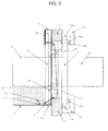
- FIG. 3 shows the working-tank sealing mechanism of FIG. 1 in a completely drained state.
- reference numeral 15 denotes the level of the working fluid.
- FIG. 4 is a perspective view of the pre-sealing bellows cover 3.
- the clean working fluid (makeup water) is introduced into the space inside the pre-sealing bellows cover 3 through the fluid supply pipe 8 ( FIG. 1 ).
- the pre-sealing bellows cover 3 is formed with openings 20 through which the clean working fluid is introduced into the pre-sealing unit P.
- the baffle plates 3a for regulating the flow-of the working fluid in the internal space are attached individually to a plurality of longitudinal portions of the pre-sealing bellows cover 3.
- the length of each arrow that represents the water current from each corresponding opening 20 indicates the strength of the water current.
- reference numeral 3d denotes a region that covers those openings 20 which cannot be reached by the working fluid.
- the feed of the working fluid (makeup water) from the pre-sealing bellows cover 3 into the pre-sealing unit P is increased as a whole, in order to avoid the reduction of the water currents 21 from the openings 20 near the supply port sides 3b and 3c, however, the life of a filter filtering out contaminant, which may be used in the wire-cut electric discharge machine, is inevitably reduced.
- the object of the present invention is to provide a pre-sealing unit for a wire-cut electric discharge machine, capable of efficiently discharging contaminants at low cost by modifying a method for introducing a clean working fluid to the pre-sealing unit.
- a pre-sealing unit for a wire-cut electric discharge machine is attached to a sealing mechanism in a lower-arm insertion portion of a working tank mounted on a movable table.
- the pre-sealing unit comprises partition unit which surrounds the seal ing mechanism from within the working tank, working-fluid supply unit which introduces a clean working fluid into a space defined by the sealing mechanism and the partition unit, under a pressure higher than the pressure of the working fluid present outside the space, bellows unit having an operating range corresponding to the range of movement of the movable table in the direction perpendicular to the axis of a lower arm, and a movable-window closing member through which the lower arm is inserted.
- a window portion is formed on the partition unit at a portion facing the inside of the working tank, and the bellows unit and the movable-window closing member are arranged at the window portion so that the greater part of the window portion is closed thereby.
- a supply pipe the longitudinal direction of which is perpendicular to the axis of the lower arm and which has a plurality of openings on the sealing mechanism side thereof, is located at the upper part of the bellows unit, whereby the clean working fluid is allowed to be introduced into the pre-sealing unit through the openings of the supply pipe.
- the sum total of the respective cross-sectional areas of the openings of the supply pipe may be smaller than the cross-sectional area of a supply port leading to the supply pipe.
- the bellows unit may be supported by a cover to which the supply pipe is attached.
- a pre-sealing unit for a wire-cut electric discharge machine capable of efficiently discharging contaminants at low cost by modifying a method for introducing a clean working fluid to the pre-sealing unit.
- a pre-sealing bellows cover used in one embodiment of a pre-sealing unit according to the present invention will be described with reference to FIG. 7 .
- a pre-sealing bellows cover 3 with the structure shown in FIG. 7 is used in the pre-sealing unit according to the present invention. More specifically, the pre-sealing unit according to the present invention differs from the prior art pre-sealing unit described with reference to FIGS. 1 to 6 only in the structure of the pre-sealing bellows cover for use as a supply pipe through which a clean working fluid is introduced into the pre-sealing unit attached to a working tank. As regards other structures, these two pre-sealing units resemble each other.
- the pre-sealing bellows cover 3 is formed with a plurality of openings 22 arranged longitudinally relative to the cover 3.
- the openings 22 of the pre-sealing bellows cover 3 are designed so that the sum total of their respective cross-sectional areas is smaller than the cross-sectional area of a working-fluid supply port side 3b of the pre-sealing bellows cover 3.
- the internal space of the pre-sealing bellows cover 3 can be filled up with the working fluid (makeup water) introduced through a working-fluid compensating port 24 without regard to the flow rate of the working fluid.
- the compensating port 24 is supplied with the working fluid by a working-fluid supply pump (not shown) under a pressure higher than the pressure of the working fluid present within a working tank 1, that is, present outside partition means that surrounds a sealing mechanism S from within the working tank 1.
- a water current 23 that is discharged into the working tank 1 through the openings 22 of the pre-sealing bellows cover 3 can be adjusted so that its strength is uniform in the longitudinal direction of the pre-sealing bellows cover 3, as shown in FIG. 7 .
- Each of the openings 22 in the pre-sealing bellows cover 3 is not limited to the rectangular shape shown in FIG. 7 , and may be square, circular, or elliptical.
- a pipe having a plurality of openings may be arranged side by side with the pre-sealing bellows cover 3 so that the clean working fluid (makeup water) can be introduced toward the pre-sealing bellows cover 3 through the openings of the pipe.
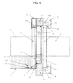
- FIGS. 8 and 9 are sectional views of the working-tank sealing mechanism of FIG. 1 with the pre-sealing bellows cover of FIG. 7 used in the pre-sealing unit, taken in the directions of arrows B and A, respectively, of FIG. 1 .
- the sealing mechanism shown in FIG. 9 is completely drained.
- the working fluid makeup water
- the working fluid is uniformly discharged into the pre-sealing unit P through the openings 22 of the pre-sealing bellows cover 3.
- the working fluid can be equally distributed to the upper part of the sealing mechanism in the pre-sealing unit P.
- a working fluid level 15 in the working tank 1 becomes lower than the height level of the pre-sealing unit P (that is, if the working-tank sealing mechanism is completely drained), as shown in FIG. 9 , the water level in the pre-sealing unit P inevitably lowers. Thus, the working tank 1 cannot be kept filled with the clean working fluid.
- the working fluid can be equally supplied to the upper part of the sealing mechanism by using the pre-sealing bellows cover 3 with the openings 22 shown in FIG. 7 in the pre-sealing unit. Accordingly, the clean working fluid can be reliably introduced to the sealing mechanism without being affected by the working fluid level 15 in the working tank 1, so that contaminants can be discharged from the pre-sealing unit. Thus, the durability and maintenance cycle of each part of the sealing mechanism can be considerably improved.
Landscapes
- Chemical & Material Sciences (AREA)
- Chemical Kinetics & Catalysis (AREA)
- Electrochemistry (AREA)
- Engineering & Computer Science (AREA)
- Mechanical Engineering (AREA)
- Electrical Discharge Machining, Electrochemical Machining, And Combined Machining (AREA)
- Bending Of Plates, Rods, And Pipes (AREA)
Applications Claiming Priority (1)
| Application Number | Priority Date | Filing Date | Title |
|---|---|---|---|
| JP2011194138A JP5291771B2 (ja) | 2011-09-06 | 2011-09-06 | ワイヤカット放電加工機のプレシール装置 |
Publications (3)
| Publication Number | Publication Date |
|---|---|
| EP2567771A2 true EP2567771A2 (de) | 2013-03-13 |
| EP2567771A3 EP2567771A3 (de) | 2014-01-29 |
| EP2567771B1 EP2567771B1 (de) | 2016-05-18 |
Family
ID=46319036
Family Applications (1)
| Application Number | Title | Priority Date | Filing Date |
|---|---|---|---|
| EP12172871.1A Active EP2567771B1 (de) | 2011-09-06 | 2012-06-21 | Dichtungseinheit für eine Drahterodiermaschine |
Country Status (4)
| Country | Link |
|---|---|
| US (1) | US8710391B2 (de) |
| EP (1) | EP2567771B1 (de) |
| JP (1) | JP5291771B2 (de) |
| CN (1) | CN102974905B (de) |
Families Citing this family (3)
| Publication number | Priority date | Publication date | Assignee | Title |
|---|---|---|---|---|
| JP6280010B2 (ja) * | 2014-09-25 | 2018-02-14 | ファナック株式会社 | 回転軸装置および前記回転軸装置を備えた放電加工機 |
| WO2022009953A1 (ja) | 2020-07-10 | 2022-01-13 | ファナック株式会社 | シール装置およびワイヤ放電加工機 |
| WO2022009952A1 (ja) * | 2020-07-10 | 2022-01-13 | ファナック株式会社 | シール装置およびワイヤ放電加工機 |
Citations (1)
| Publication number | Priority date | Publication date | Assignee | Title |
|---|---|---|---|---|
| JPH0760550A (ja) | 1993-08-27 | 1995-03-07 | Fanuc Ltd | ワイヤ放電加工機の加工槽プレシール装置 |
Family Cites Families (12)
| Publication number | Priority date | Publication date | Assignee | Title |
|---|---|---|---|---|
| JPH01257522A (ja) * | 1988-04-07 | 1989-10-13 | Mitsubishi Electric Corp | ワイヤ放電加工装置 |
| JPH0739056B2 (ja) * | 1988-10-17 | 1995-05-01 | 三菱電機株式会社 | ワイヤ放電加工装置 |
| JPH0724169Y2 (ja) * | 1989-01-27 | 1995-06-05 | 三菱電機株式会社 | ワイヤ放電加工装置 |
| DE4019662C2 (de) * | 1990-06-20 | 1994-07-14 | Agie Ag Ind Elektronik | Maschine zum funkenerosiven Schneiden mit einem die Rückwand des Arbeitsflüssigkeits-Behälters durchquerenden Führungsarm |
| JPH04146025A (ja) * | 1990-10-03 | 1992-05-20 | Sodick Co Ltd | ワイヤカット放電加工機のアームのシール装置 |
| JPH0796167B2 (ja) * | 1990-10-20 | 1995-10-18 | 株式会社牧野フライス製作所 | ワイヤ放電加工機のシール装置 |
| JP2691487B2 (ja) * | 1992-01-18 | 1997-12-17 | ファナック株式会社 | ワイヤカット放電加工装置 |
| JP3669813B2 (ja) * | 1997-05-01 | 2005-07-13 | 西部電機株式会社 | 浸漬式ワイヤ放電加工機 |
| JP3609244B2 (ja) * | 1997-10-29 | 2005-01-12 | 西部電機株式会社 | 浸漬式ワイヤ放電加工機 |
| DE10085445B4 (de) * | 2000-02-25 | 2008-06-19 | Mitsubishi Denki K.K. | Drahterodierbearbeitungseinrichtung |
| JP4331089B2 (ja) * | 2004-11-05 | 2009-09-16 | 西部電機株式会社 | ワイヤ放電加工機 |
| JP4109269B2 (ja) * | 2005-04-25 | 2008-07-02 | ファナック株式会社 | ワイヤカット放電加工機におけるシール構造 |
-
2011
- 2011-09-06 JP JP2011194138A patent/JP5291771B2/ja active Active
-
2012
- 2012-06-15 US US13/524,104 patent/US8710391B2/en active Active
- 2012-06-21 EP EP12172871.1A patent/EP2567771B1/de active Active
- 2012-08-30 CN CN201210315921.8A patent/CN102974905B/zh active Active
Patent Citations (1)
| Publication number | Priority date | Publication date | Assignee | Title |
|---|---|---|---|---|
| JPH0760550A (ja) | 1993-08-27 | 1995-03-07 | Fanuc Ltd | ワイヤ放電加工機の加工槽プレシール装置 |
Also Published As
| Publication number | Publication date |
|---|---|
| CN102974905A (zh) | 2013-03-20 |
| JP2013052497A (ja) | 2013-03-21 |
| EP2567771A3 (de) | 2014-01-29 |
| CN102974905B (zh) | 2014-04-16 |
| EP2567771B1 (de) | 2016-05-18 |
| JP5291771B2 (ja) | 2013-09-18 |
| US20130056445A1 (en) | 2013-03-07 |
| US8710391B2 (en) | 2014-04-29 |
Similar Documents
| Publication | Publication Date | Title |
|---|---|---|
| EP2567771B1 (de) | Dichtungseinheit für eine Drahterodiermaschine | |
| KR101630585B1 (ko) | 제품 홀딩 기기 및 처리 방법 | |
| CN1118628C (zh) | 用于微型泵的微加工过滤器 | |
| CN104625260B (zh) | 电解加工装置 | |
| KR100401367B1 (ko) | 방전 가공기 및 공작 기계 조립을 위한 모듈 세트 | |
| DE102009043630A1 (de) | Verfahren und Vorrichtung zum Galvanisier-Vorbehandeln eines Zylinderblocks | |
| CN104454677A (zh) | 一种液压油箱 | |
| WO2026008355A1 (de) | Planartransportsystem für eine anlage zum verarbeiten pharmazeutischer behälter und anlage zum verarbeiten pharmazeutischer behälter | |
| KR20120020404A (ko) | 튜브 벤딩용 맨드릴 | |
| EP3363535A1 (de) | Schwimm- und verdunstungsunterdrückungsverfahren | |
| US20070065305A1 (en) | Diaphragm pump for the transport of liquids | |
| EP0610974B1 (de) | Funkenerosive Drahtschneideinrichtung | |
| DE102017211365A1 (de) | Energiespeichereinrichtung für ein Kraftfahrzeug und Kraftfahrzeug | |
| CN102216014A (zh) | 用于对工件进行电化学加工的装置 | |
| EP0667202B1 (de) | Schutzanordnung für die dichtung des bearbeitungsflüssigkeitbehälters einer drahtschneidefunkenerosionsmaschine | |
| CN101111347A (zh) | 线性滚动轴承,具有设置在导向托架端面上的u形刮削器 | |
| DE102014226143B4 (de) | Speicherzellenanordnung und Speicherzellenbetriebsanordnung mit einer Speicherzellenanordnung | |
| CN115803136B (zh) | 密封装置以及线放电加工机 | |
| JP2015077646A (ja) | 工作機械の加工液タンク | |
| CN100429029C (zh) | 电火花线切割机的密封结构 | |
| DE102015207469B4 (de) | Versorgungseinrichtung für viskose Medien | |
| JPWO2001062423A1 (ja) | ワイヤ放電加工装置 | |
| AU594042B2 (en) | Device for metal strip electrolytic processing | |
| JP3609244B2 (ja) | 浸漬式ワイヤ放電加工機 | |
| CN102612607B (zh) | 线性引导装置 |
Legal Events
| Date | Code | Title | Description |
|---|---|---|---|
| PUAI | Public reference made under article 153(3) epc to a published international application that has entered the european phase |
Free format text: ORIGINAL CODE: 0009012 |
|
| AK | Designated contracting states |
Kind code of ref document: A2 Designated state(s): AL AT BE BG CH CY CZ DE DK EE ES FI FR GB GR HR HU IE IS IT LI LT LU LV MC MK MT NL NO PL PT RO RS SE SI SK SM TR |
|
| AX | Request for extension of the european patent |
Extension state: BA ME |
|
| PUAL | Search report despatched |
Free format text: ORIGINAL CODE: 0009013 |
|
| AK | Designated contracting states |
Kind code of ref document: A3 Designated state(s): AL AT BE BG CH CY CZ DE DK EE ES FI FR GB GR HR HU IE IS IT LI LT LU LV MC MK MT NL NO PL PT RO RS SE SI SK SM TR |
|
| AX | Request for extension of the european patent |
Extension state: BA ME |
|
| RIC1 | Information provided on ipc code assigned before grant |
Ipc: B23H 7/02 20060101AFI20131220BHEP |
|
| 17P | Request for examination filed |
Effective date: 20140716 |
|
| RBV | Designated contracting states (corrected) |
Designated state(s): AL AT BE BG CH CY CZ DE DK EE ES FI FR GB GR HR HU IE IS IT LI LT LU LV MC MK MT NL NO PL PT RO RS SE SI SK SM TR |
|
| GRAP | Despatch of communication of intention to grant a patent |
Free format text: ORIGINAL CODE: EPIDOSNIGR1 |
|
| INTG | Intention to grant announced |
Effective date: 20151215 |
|
| GRAS | Grant fee paid |
Free format text: ORIGINAL CODE: EPIDOSNIGR3 |
|
| GRAA | (expected) grant |
Free format text: ORIGINAL CODE: 0009210 |
|
| AK | Designated contracting states |
Kind code of ref document: B1 Designated state(s): AL AT BE BG CH CY CZ DE DK EE ES FI FR GB GR HR HU IE IS IT LI LT LU LV MC MK MT NL NO PL PT RO RS SE SI SK SM TR |
|
| REG | Reference to a national code |
Ref country code: GB Ref legal event code: FG4D |
|
| REG | Reference to a national code |
Ref country code: CH Ref legal event code: NV Representative=s name: DR. LUSUARDI AG, CH Ref country code: CH Ref legal event code: EP |
|
| REG | Reference to a national code |
Ref country code: IE Ref legal event code: FG4D Ref country code: AT Ref legal event code: REF Ref document number: 799992 Country of ref document: AT Kind code of ref document: T Effective date: 20160615 |
|
| REG | Reference to a national code |
Ref country code: DE Ref legal event code: R096 Ref document number: 602012018441 Country of ref document: DE |
|
| REG | Reference to a national code |
Ref country code: NL Ref legal event code: MP Effective date: 20160518 |
|
| REG | Reference to a national code |
Ref country code: LT Ref legal event code: MG4D |
|
| PG25 | Lapsed in a contracting state [announced via postgrant information from national office to epo] |
Ref country code: FI Free format text: LAPSE BECAUSE OF FAILURE TO SUBMIT A TRANSLATION OF THE DESCRIPTION OR TO PAY THE FEE WITHIN THE PRESCRIBED TIME-LIMIT Effective date: 20160518 Ref country code: NL Free format text: LAPSE BECAUSE OF FAILURE TO SUBMIT A TRANSLATION OF THE DESCRIPTION OR TO PAY THE FEE WITHIN THE PRESCRIBED TIME-LIMIT Effective date: 20160518 Ref country code: LT Free format text: LAPSE BECAUSE OF FAILURE TO SUBMIT A TRANSLATION OF THE DESCRIPTION OR TO PAY THE FEE WITHIN THE PRESCRIBED TIME-LIMIT Effective date: 20160518 Ref country code: NO Free format text: LAPSE BECAUSE OF FAILURE TO SUBMIT A TRANSLATION OF THE DESCRIPTION OR TO PAY THE FEE WITHIN THE PRESCRIBED TIME-LIMIT Effective date: 20160818 |
|
| REG | Reference to a national code |
Ref country code: AT Ref legal event code: MK05 Ref document number: 799992 Country of ref document: AT Kind code of ref document: T Effective date: 20160518 |
|
| PG25 | Lapsed in a contracting state [announced via postgrant information from national office to epo] |
Ref country code: LV Free format text: LAPSE BECAUSE OF FAILURE TO SUBMIT A TRANSLATION OF THE DESCRIPTION OR TO PAY THE FEE WITHIN THE PRESCRIBED TIME-LIMIT Effective date: 20160518 Ref country code: HR Free format text: LAPSE BECAUSE OF FAILURE TO SUBMIT A TRANSLATION OF THE DESCRIPTION OR TO PAY THE FEE WITHIN THE PRESCRIBED TIME-LIMIT Effective date: 20160518 Ref country code: ES Free format text: LAPSE BECAUSE OF FAILURE TO SUBMIT A TRANSLATION OF THE DESCRIPTION OR TO PAY THE FEE WITHIN THE PRESCRIBED TIME-LIMIT Effective date: 20160518 Ref country code: RS Free format text: LAPSE BECAUSE OF FAILURE TO SUBMIT A TRANSLATION OF THE DESCRIPTION OR TO PAY THE FEE WITHIN THE PRESCRIBED TIME-LIMIT Effective date: 20160518 Ref country code: SE Free format text: LAPSE BECAUSE OF FAILURE TO SUBMIT A TRANSLATION OF THE DESCRIPTION OR TO PAY THE FEE WITHIN THE PRESCRIBED TIME-LIMIT Effective date: 20160518 Ref country code: PT Free format text: LAPSE BECAUSE OF FAILURE TO SUBMIT A TRANSLATION OF THE DESCRIPTION OR TO PAY THE FEE WITHIN THE PRESCRIBED TIME-LIMIT Effective date: 20160919 Ref country code: GR Free format text: LAPSE BECAUSE OF FAILURE TO SUBMIT A TRANSLATION OF THE DESCRIPTION OR TO PAY THE FEE WITHIN THE PRESCRIBED TIME-LIMIT Effective date: 20160819 |
|
| PG25 | Lapsed in a contracting state [announced via postgrant information from national office to epo] |
Ref country code: BE Free format text: LAPSE BECAUSE OF NON-PAYMENT OF DUE FEES Effective date: 20160630 Ref country code: IT Free format text: LAPSE BECAUSE OF FAILURE TO SUBMIT A TRANSLATION OF THE DESCRIPTION OR TO PAY THE FEE WITHIN THE PRESCRIBED TIME-LIMIT Effective date: 20160518 |
|
| PG25 | Lapsed in a contracting state [announced via postgrant information from national office to epo] |
Ref country code: RO Free format text: LAPSE BECAUSE OF FAILURE TO SUBMIT A TRANSLATION OF THE DESCRIPTION OR TO PAY THE FEE WITHIN THE PRESCRIBED TIME-LIMIT Effective date: 20160518 Ref country code: SK Free format text: LAPSE BECAUSE OF FAILURE TO SUBMIT A TRANSLATION OF THE DESCRIPTION OR TO PAY THE FEE WITHIN THE PRESCRIBED TIME-LIMIT Effective date: 20160518 Ref country code: CZ Free format text: LAPSE BECAUSE OF FAILURE TO SUBMIT A TRANSLATION OF THE DESCRIPTION OR TO PAY THE FEE WITHIN THE PRESCRIBED TIME-LIMIT Effective date: 20160518 Ref country code: EE Free format text: LAPSE BECAUSE OF FAILURE TO SUBMIT A TRANSLATION OF THE DESCRIPTION OR TO PAY THE FEE WITHIN THE PRESCRIBED TIME-LIMIT Effective date: 20160518 Ref country code: DK Free format text: LAPSE BECAUSE OF FAILURE TO SUBMIT A TRANSLATION OF THE DESCRIPTION OR TO PAY THE FEE WITHIN THE PRESCRIBED TIME-LIMIT Effective date: 20160518 |
|
| REG | Reference to a national code |
Ref country code: DE Ref legal event code: R097 Ref document number: 602012018441 Country of ref document: DE |
|
| PG25 | Lapsed in a contracting state [announced via postgrant information from national office to epo] |
Ref country code: BE Free format text: LAPSE BECAUSE OF FAILURE TO SUBMIT A TRANSLATION OF THE DESCRIPTION OR TO PAY THE FEE WITHIN THE PRESCRIBED TIME-LIMIT Effective date: 20160518 Ref country code: AT Free format text: LAPSE BECAUSE OF FAILURE TO SUBMIT A TRANSLATION OF THE DESCRIPTION OR TO PAY THE FEE WITHIN THE PRESCRIBED TIME-LIMIT Effective date: 20160518 Ref country code: SM Free format text: LAPSE BECAUSE OF FAILURE TO SUBMIT A TRANSLATION OF THE DESCRIPTION OR TO PAY THE FEE WITHIN THE PRESCRIBED TIME-LIMIT Effective date: 20160518 Ref country code: PL Free format text: LAPSE BECAUSE OF FAILURE TO SUBMIT A TRANSLATION OF THE DESCRIPTION OR TO PAY THE FEE WITHIN THE PRESCRIBED TIME-LIMIT Effective date: 20160518 |
|
| REG | Reference to a national code |
Ref country code: IE Ref legal event code: MM4A |
|
| PLBE | No opposition filed within time limit |
Free format text: ORIGINAL CODE: 0009261 |
|
| STAA | Information on the status of an ep patent application or granted ep patent |
Free format text: STATUS: NO OPPOSITION FILED WITHIN TIME LIMIT |
|
| PG25 | Lapsed in a contracting state [announced via postgrant information from national office to epo] |
Ref country code: MC Free format text: LAPSE BECAUSE OF FAILURE TO SUBMIT A TRANSLATION OF THE DESCRIPTION OR TO PAY THE FEE WITHIN THE PRESCRIBED TIME-LIMIT Effective date: 20160518 |
|
| REG | Reference to a national code |
Ref country code: FR Ref legal event code: ST Effective date: 20170228 |
|
| 26N | No opposition filed |
Effective date: 20170221 |
|
| GBPC | Gb: european patent ceased through non-payment of renewal fee |
Effective date: 20160818 |
|
| PG25 | Lapsed in a contracting state [announced via postgrant information from national office to epo] |
Ref country code: FR Free format text: LAPSE BECAUSE OF NON-PAYMENT OF DUE FEES Effective date: 20160718 |
|
| PG25 | Lapsed in a contracting state [announced via postgrant information from national office to epo] |
Ref country code: SI Free format text: LAPSE BECAUSE OF FAILURE TO SUBMIT A TRANSLATION OF THE DESCRIPTION OR TO PAY THE FEE WITHIN THE PRESCRIBED TIME-LIMIT Effective date: 20160518 Ref country code: IE Free format text: LAPSE BECAUSE OF NON-PAYMENT OF DUE FEES Effective date: 20160621 |
|
| PG25 | Lapsed in a contracting state [announced via postgrant information from national office to epo] |
Ref country code: GB Free format text: LAPSE BECAUSE OF NON-PAYMENT OF DUE FEES Effective date: 20160818 |
|
| PG25 | Lapsed in a contracting state [announced via postgrant information from national office to epo] |
Ref country code: HU Free format text: LAPSE BECAUSE OF FAILURE TO SUBMIT A TRANSLATION OF THE DESCRIPTION OR TO PAY THE FEE WITHIN THE PRESCRIBED TIME-LIMIT; INVALID AB INITIO Effective date: 20120621 Ref country code: CY Free format text: LAPSE BECAUSE OF FAILURE TO SUBMIT A TRANSLATION OF THE DESCRIPTION OR TO PAY THE FEE WITHIN THE PRESCRIBED TIME-LIMIT Effective date: 20160518 |
|
| PG25 | Lapsed in a contracting state [announced via postgrant information from national office to epo] |
Ref country code: MK Free format text: LAPSE BECAUSE OF FAILURE TO SUBMIT A TRANSLATION OF THE DESCRIPTION OR TO PAY THE FEE WITHIN THE PRESCRIBED TIME-LIMIT Effective date: 20160518 Ref country code: IS Free format text: LAPSE BECAUSE OF FAILURE TO SUBMIT A TRANSLATION OF THE DESCRIPTION OR TO PAY THE FEE WITHIN THE PRESCRIBED TIME-LIMIT Effective date: 20160518 Ref country code: LU Free format text: LAPSE BECAUSE OF NON-PAYMENT OF DUE FEES Effective date: 20160621 Ref country code: TR Free format text: LAPSE BECAUSE OF FAILURE TO SUBMIT A TRANSLATION OF THE DESCRIPTION OR TO PAY THE FEE WITHIN THE PRESCRIBED TIME-LIMIT Effective date: 20160518 Ref country code: MT Free format text: LAPSE BECAUSE OF NON-PAYMENT OF DUE FEES Effective date: 20160630 |
|
| PG25 | Lapsed in a contracting state [announced via postgrant information from national office to epo] |
Ref country code: BG Free format text: LAPSE BECAUSE OF FAILURE TO SUBMIT A TRANSLATION OF THE DESCRIPTION OR TO PAY THE FEE WITHIN THE PRESCRIBED TIME-LIMIT Effective date: 20160518 |
|
| PG25 | Lapsed in a contracting state [announced via postgrant information from national office to epo] |
Ref country code: AL Free format text: LAPSE BECAUSE OF FAILURE TO SUBMIT A TRANSLATION OF THE DESCRIPTION OR TO PAY THE FEE WITHIN THE PRESCRIBED TIME-LIMIT Effective date: 20160518 |
|
| REG | Reference to a national code |
Ref country code: DE Ref legal event code: R082 Ref document number: 602012018441 Country of ref document: DE Representative=s name: HL KEMPNER PATENTANWAELTE, SOLICITORS (ENGLAND, DE Ref country code: DE Ref legal event code: R082 Ref document number: 602012018441 Country of ref document: DE Representative=s name: HL KEMPNER PATENTANWALT, RECHTSANWALT, SOLICIT, DE Ref country code: DE Ref legal event code: R082 Ref document number: 602012018441 Country of ref document: DE Representative=s name: HL KEMPNER PARTG MBB, DE |
|
| PGFP | Annual fee paid to national office [announced via postgrant information from national office to epo] |
Ref country code: DE Payment date: 20250520 Year of fee payment: 14 |
|
| PGFP | Annual fee paid to national office [announced via postgrant information from national office to epo] |
Ref country code: CH Payment date: 20250701 Year of fee payment: 14 |