EP2566652B1 - Ultraschall-schweissvorrichtung und verfahren zur herstellung einer schweissverbindung mittels ultraschall - Google Patents
Ultraschall-schweissvorrichtung und verfahren zur herstellung einer schweissverbindung mittels ultraschall Download PDFInfo
- Publication number
- EP2566652B1 EP2566652B1 EP11718086.9A EP11718086A EP2566652B1 EP 2566652 B1 EP2566652 B1 EP 2566652B1 EP 11718086 A EP11718086 A EP 11718086A EP 2566652 B1 EP2566652 B1 EP 2566652B1
- Authority
- EP
- European Patent Office
- Prior art keywords
- torsion
- ultrasonic welding
- welding device
- sonotrode
- working surface
- Prior art date
- Legal status (The legal status is an assumption and is not a legal conclusion. Google has not performed a legal analysis and makes no representation as to the accuracy of the status listed.)
- Active
Links
Images


Classifications
-
- B—PERFORMING OPERATIONS; TRANSPORTING
- B23—MACHINE TOOLS; METAL-WORKING NOT OTHERWISE PROVIDED FOR
- B23K—SOLDERING OR UNSOLDERING; WELDING; CLADDING OR PLATING BY SOLDERING OR WELDING; CUTTING BY APPLYING HEAT LOCALLY, e.g. FLAME CUTTING; WORKING BY LASER BEAM
- B23K20/00—Non-electric welding by applying impact or other pressure, with or without the application of heat, e.g. cladding or plating
- B23K20/10—Non-electric welding by applying impact or other pressure, with or without the application of heat, e.g. cladding or plating making use of vibrations, e.g. ultrasonic welding
- B23K20/106—Features related to sonotrodes
-
- B—PERFORMING OPERATIONS; TRANSPORTING
- B06—GENERATING OR TRANSMITTING MECHANICAL VIBRATIONS IN GENERAL
- B06B—METHODS OR APPARATUS FOR GENERATING OR TRANSMITTING MECHANICAL VIBRATIONS OF INFRASONIC, SONIC, OR ULTRASONIC FREQUENCY, e.g. FOR PERFORMING MECHANICAL WORK IN GENERAL
- B06B3/00—Methods or apparatus specially adapted for transmitting mechanical vibrations of infrasonic, sonic, or ultrasonic frequency
-
- B—PERFORMING OPERATIONS; TRANSPORTING
- B06—GENERATING OR TRANSMITTING MECHANICAL VIBRATIONS IN GENERAL
- B06B—METHODS OR APPARATUS FOR GENERATING OR TRANSMITTING MECHANICAL VIBRATIONS OF INFRASONIC, SONIC, OR ULTRASONIC FREQUENCY, e.g. FOR PERFORMING MECHANICAL WORK IN GENERAL
- B06B2201/00—Indexing scheme associated with B06B1/0207 for details covered by B06B1/0207 but not provided for in any of its subgroups
- B06B2201/70—Specific application
- B06B2201/72—Welding, joining, soldering
Definitions
- the invention relates to a Torsionssonotrode, an ultrasonic welding apparatus and a method for producing a welded connection by means of ultrasound.
- the invention generally relates to the field of ultrasonic welding. It relates in particular to the field of ultrasonic welding of metallic components.
- the components are moved by the action of an ultrasonic vibration substantially parallel to a welding surface relative to each other, at the same time perpendicular to a pressure or a welding force is exerted on the components to be connected.
- the ultrasound vibration makes it possible to rupture and displace the contamination and oxide layers which are mostly present on sub-surfaces.
- the resulting direct contact of the pure metal surfaces leads to a permanent cohesive connection of the metallic components.
- the US 5,603,444 discloses an ultrasonic welding apparatus having a longitudinal sonotrode, the working surface of which is also reciprocated along a straight path.
- the Longitudinalsonotrode is connected in a conventional manner via screw and with the interposition of a booster with a converter.
- a pressure device for generating a pressure on the work surface is provided. The pressure generated by the pressure device is applied via the nodal lines of the longitudinal sonotrode.
- the EP 1 930 148 A1 discloses an ultrasonic welding apparatus using a so-called torsion sonotrode. It is a substantially rotationally symmetrical sonotrode, at one end face of the work surface is provided. In the vicinity of the other end face, the torsion sonotrode converters are coupled to a circumferential surface, with which a vibration directed about a torsion axis is transmitted to the torsion sonotrode. As a result, the working surface pressed against the components to be connected reciprocates on an arc line corresponding to the circumference of the torsion sonotrode.
- the disadvantage here is that a power transmitted to the components to be connected in a radially inner portion of the working surface is smaller than in a radial outer section of the work surface. As a result, the welded joint between the components to be joined is uneven.
- the object of the invention is to eliminate the disadvantages of the prior art.
- a sonotrode should be specified with which the efficiency provided by the converter can be transferred to the work surface with improved efficiency.
- the improved efficiency of the power transmission should be achieved, in particular, when a high pressure is exerted.
- an ultrasonic welding device and a method for producing a welded connection by means of ultrasound are to be specified, which enable an efficient and uniform production of a welded joint between components to be joined.
- an ultrasonic welding apparatus which comprises a Torsionssonotrode with two opposite end faces and a peripheral surface surrounding a torsion, on the at least one working surface with a radial Distance from the torsion axis is provided.
- the working surface in departure from the state of the art, is no longer located at one of the front sides but at the peripheral surface surrounding the torsion axis.
- all surface elements of the work surface have substantially the same radial distance from the torsion axis. It can have a significant A uniform power to be transferred to the components to be welded portion of the work area.
- a welded joint produced with the sonotrode according to the invention is uniform.
- the proposed torsion sonotrode allows a substantially lossless transmission of the power provided by the converter on the work surface. There are no tilting movements on the joining surfaces between the Torsion Sonotrode, a possibly provided booster and the converter.
- the work surface performs a torsional movement about the torsion axis, but not a longitudinal movement parallel to the torsion axis.
- the proposed Torsionssonotrode is particularly suitable for producing a welded joint between metallic components, for example between a strand and a plug.
- An axial length 1 of the Torsionssonotrode is suitably chosen so that these at a given frequency v n performs a standing oscillation or natural oscillation with the wavelength ⁇ .
- the work surface is provided centrally on the peripheral surface.
- a length 1 of the torsion sonotrode may also be ⁇ / 2, 3 ⁇ / 2, 2 ⁇ , etc.
- the torsion sonotrode on the peripheral surface on both sides of the at least one working surface in each case one, preferably radially projecting annular surface, which lies with respect to a wavelength of self-oscillation of the Torsion sonotrode on a node line.
- an axial length 1 of the torsion sonotrode is selected such that, at a given ultrasonic frequency, it corresponds exactly to the wavelength ⁇ of the natural vibration.
- the nodal lines are approximately 1/4 and 3/4 of the length 1 of the Torsion Sonotrode.
- the working surface may in this case be arranged between the nodal lines and is located approximately at 1/2 of the length 1 of the torsion sonotrode.
- the torsion sonotrode is symmetrical with respect to a symmetry plane extending perpendicularly through the torsion axis.
- a contour or an outline of the working surface is formed symmetrically with respect to the plane of symmetry.
- the plane of symmetry extends through the at least one working surface and the working surface is symmetrical with respect to the plane of symmetry.
- Such a design of the torsion sonotrode is particularly simple.
- the at least one work surface is centered with respect to the axial length 1 of the Torsion sonotrode arranged on the peripheral surface.
- the torsion sonotrode comprises a center part which comprises at least one work surface and which is detachably connected to end pieces extending on both sides thereof, each having one of the end faces.
- each of the end pieces have an annular surface.
- a connection between the end pieces and the middle part may for example be a screw connection. It may also be that the two end pieces are directly connected to each other, for example by means of a screw, and the middle part is formed as a ring, which is shrunk onto the connected end pieces.
- the working surface is curved with a predetermined radius in the circumferential direction.
- the radius has its origin in the torsion axis, i. H. in this case, the work surface is therefore on a circumference around the torsion axis.
- the work surface is a radially projecting, circumferential ring work surface.
- a ring work surface allows particularly long service life of Torsionssonotrode. If a portion of the ring work surface is consumed, can by twisting the Torsionssonotrode by a predetermined angle another unused portion of the ring work surface can be provided for making further welds.
- the producible with the proposed Torsionssonotrode number of welded joints over conventional sonotrodes can be multiplied.
- n work surfaces are provided, which are arranged uniformly over the circumference at an angle of 360 ° / n, where n is an integer> 1.
- the work surfaces are designed, for example, anvil-like and project radially from a peripheral surface of the Torsionssonotrode.
- 2, 3, 4, 5, 6, 7, 8 or more such work surfaces can be provided.
- the provision of a plurality of work surfaces allows - similar to the provision of a ring work surface - a quick change in the event of consumption of a work surface.
- Such a torsion sonotrode has a particularly long service life. A change from one work surface to another work surface can be done by a simple rotation of the torsion sonotrode. Replacement or disassembly is not required.
- the work surface has a structure, preferably grooves on.
- the grooves may extend axially or obliquely with respect to the axial direction. They can be arranged crossed.
- PCD polycrystalline diamond
- Such a PCD layer can be soldered onto the work surface, for example. This can increase the durability of the work surface and / or an undesirable connection during welding, especially with aluminum, can be avoided.
- Ultrasonic welding device succeeds in transmitting a high power to the components to be joined, It can thus relatively thick metallic components are welded in excellent quality.
- the converter is radially connected to a Torsionsschwingelement which is coupled to one of the end sides of the Torsionssonotrode.
- the torsional vibration element is, for example, a cylindrical rod.
- Such torsional vibration devices are known per se in the prior art. It is referred to the EP 1 930 148 A1 , which in [0039] and [0040] as well as the FIGS. 2 and 3 disclosed suitable torsional vibration devices. The disclosure of the document is included in this regard.
- the Torsionsschwingelement is connected with the interposition of a booster with the front side of the Torsionssonotrode.
- the booster has the function of changing the amplitude provided by the converter and forwarding it to the torsion sonotrode according to the invention.
- the amplitude can be reduced or increased.
- booster which provided by the converter Increase the amplitude.
- the translations of a booster may be, for example, 1: 1.5 to 1: 2.
- a further converter for generating an ultrasonic vibration directed about the torsion axis can be coupled to the other of the end faces of the torsion sonotrode.
- the further converter can be connected radially to a further torsional vibration element, which is coupled to the other end side of the Torsionssonotrode.
- a corresponding further torsional vibration device can be constructed identical to the aforementioned torsional vibration device. It may in particular also be the case that the further torsional vibration element is connected to the other end face of the torsion sonotrode with the interposition of a further booster.
- a pressure device for generating a pressure acting substantially perpendicular to the torsion on the work surface.
- This may be, for example, a hydraulically, pneumatically or electrically operated printing device.
- the pressure on the work surface can be produced by pressing the torsion sonotrode with the working surface provided thereon against a stationary anvil or the components lying thereon. It may also be that the torsion sonotrode is fixed and the anvil is pressed against the work surface.
- the torsion sonotrode is supported with the annular surfaces provided thereon with a support device. Since the ring surfaces lie on the nodal line of the torsion sonotrode, no power is lost by the proposed support.
- the support device is connected to the printing device.
- the torsion sonotrode can thus be moved with the pressure device against a fixed anvil.
- the working surface with respect to the base describes a pendulum-like movement about the torsion axis.
- a plane of oscillation perpendicular to the torsion axis remains essentially unchanged, d. H. the working surface does not move or only insignificantly in a direction parallel to the torsion axis.
- the base may be a fixed anvil.
- the pad is designed in the manner of another torsion sonotrode according to the invention.
- the torsion sonotrode and the further torsion sonotrode advantageously oscillate in opposite directions.
- a distance between the working surface of the Torsion sonotrode and another working surface of the other Torsionssonotrode be kept substantially constant.
- the components to be welded can be held in this embodiment with respect to the Torsion sonotrode and the other Torsionssonotrode fixed holding device, which prevents dodging of the components to be welded together.
- first torsion sonotrode has two mutually opposite round end faces S1, S2, through the center of which a first G1 centric and a second threaded bore G2 extends.
- a peripheral surface U connecting the front side S1 and S2 is cylindrical here.
- the peripheral surface U is an at least partially imaginary surface, which corresponds in its cross-sectional geometry substantially the geometry of the end faces.
- the first torsion sonotrode has two substantially cylindrically shaped end sections E1, E2.
- a first end section E1 is bounded by the first end side S1 and a second end section E2 by the second end side S2.
- a first projection V1 has a first working surface A1 and a second projection V2 has a second working surface A2.
- a radial distance of the work surfaces A1, A2 from a torsion axis designated by the reference symbol T is advantageously greater than a radius of the peripheral surface U. It is for example 50 to 100 mm, preferably 60 to 90 mm.
- a radius of the peripheral surface may be 30 to 70 mm, preferably 40 to 60 mm.
- the first torsion sonotrode is in terms of in Fig. 4 shown symmetry plane SY formed symmetrically.
- the plane of symmetry SY is perpendicular to a torsion axis designated by the reference symbol T.
- the end pieces E1, E2 are here substantially rotationally symmetrical with respect to the torsion axis T.
- the in the Fig. 5 to 7 shown second torsion sonotrode has between the end pieces E1, E2 a second middle part M2, which has distributed over the circumference four anvil-like projections V1, V2, V3, V4.
- the projections V1, V2, V3, V4 are each offset by an angle of 90 ° to each other. They are symmetrical with respect to the plane of symmetry SY.
- the work surfaces A1, A2, A3, A4 provided on the peripheral surfaces of each of the projections V1, V2, V3, V4 are curved in the circumferential direction. Its radius of curvature extends from the torsion axis T and is in Fig. 7 denoted by the reference R.
- each of the work surfaces A1, A2, A3, A4 has a structure which may be formed, for example, by axially extending grooves.
- an axial length l of the Torsionssonotrode is chosen so that at a given ultrasonic frequency in Fig. 5a shown standing vibrations with the wavelength ⁇ results.
- Fig. 5a shows the amplitude +/- ⁇ of both opposite vibrational states over the length l of the torsion sonotrode.
- the zero crossings of the stationary oscillation form nodal lines on which the annular surfaces R1, R2 are located.
- the torsion sonotrode vibrates in such a way that the end pieces E1, E2 in each case move in opposite directions to the middle part M2.
- the Torsionssonotroden shown in the embodiments are advantageously made of one piece of metal. Although it is not shown in the preceding figures, but it may also be that the central part M1, M2 with the end pieces E1, E2 releasably connected, for example by means of a screw connection.
- the end faces S1, S2 may also be provided with radially extending structures, such as grooves, webs, recesses, pins or the like., Which allows a backlash-free connection with a booster or a torsion bar.
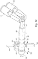
- Fig. 12 shows schematically in a perspective view the structure of an ultrasonic welding apparatus using a torsion sonotrode according to the invention, which in Fig. 12 generally designated by the reference character SO.
- the torsion sonotrode SO is at its first end face S1 with a first booster B1 by means of a screw connection firmly connected.
- the first booster B1 is in turn screwed by means of a screw connection to a first torsion bar T1, to which a first K1 and a second converter K2 are connected in a radially opposite arrangement.
- the reference AB designates an anvil which is stationary with respect to the torsion sonotrode SO.
- a support device SV schematically indicated here encompasses, for example by clamping, the annular surfaces R1, R2.
- the support device SV is connected to a pressure device D, with which the ultrasound vibration device formed from the converter K1, K2, Torsionsstab T1, Booster B1 and Torsionssonotrode SO is vertically movable relative to the anvil AB and with a pressure on the second working surface A2 and between the second working surface A2 and the anvil AB inserted to be connected components (not shown here) can be exercised.
- the ultrasonic vibrator formed from converters, boosters and Torsionssonotrode can also be arranged fixed.
- the anvil AB can be moved vertically and provided with a pressure device.
- another torsion sonotrode is provided instead of the anvil AB so another torsion sonotrode is provided.
- the opposing Torsionssonotroden oscillate in opposite directions.
Description
- Die Erfindung betrifft eine Torsionssonotrode, eine Ultraschall-Schweißvorrichtung sowie ein Verfahren zur Herstellung einer Schweißverbindung mittels Ultraschall.
- Die Erfindung betrifft allgemein das Gebiet des Ultraschallschweißens. Sie betrifft insbesondere das Gebiet des Ultraschallschweißens von metallischen Bauteilen. Dabei werden die Bauteile durch die Wirkung einer Ultraschallschwingung im Wesentlichen parallel zu einer Schweißfläche relativ zueinander bewegt, wobei gleichzeitig senkrecht dazu ein Druck bzw. eine Schweißkraft auf die zu verbindenden Bauteile ausgeübt wird. Die Ultraschallschwingung ermöglicht das Aufreißen und Verdrängen der meist auf Teiloberflächen vorhandenen Kontaminations- und Oxidschichten. Der sich daraus ergebende direkte Kontakt der reinen Metalloberflächen führt zu einer dauerhaften stoffschlüssigen Verbindung der metallischen Bauteile.
- Aus der
US 3,039,333 ist eine Ultraschall-Schweißvorrichtung bekannt, bei der eine stabförmige Sonotrode mittels radial sich davon erstreckender Koppler an zwei Konverter gekoppelt ist. Eine gegen die zu verbindenden Bauteile gedrückte Arbeitsfläche der Sonotrode wird dabei im Wesentlichen parallel zur Schweißfläche entlang eines geradlinigen Wegs hin und her bewegt. - Die
US 5,603,444 offenbart eine Ultraschall-Schweißvorrichtung mit einer Longitudinalsonotrode, deren Arbeitsfläche ebenfalls entlang eines geraden Wegs hin und her bewegt wird. Die Longitudinalsonotrode ist in herkömmlicher Weise über Schraubverbindungen und unter Zwischenschaltung eines Boosters mit einem Konverter verbunden. Ferner ist eine Druckeinrichtung zur Erzeugung eines Drucks auf die Arbeitsfläche vorgesehen. Der von der Druckeinrichtung erzeugte Druck wird über die Knotenlinien der Longitudinalsonotrode aufgebracht. - In der Praxis hat es sich herausgestellt, dass die vom Konverter bereitgestellte Ultraschallleistung nur zu einem Bruchteil auf die Arbeitsfläche übertragen wird. Nach neueren Erkenntnissen ist das darauf zurückzuführen, dass es infolge der auf die Arbeitsfläche ausgeübten Druckkraft zu Kippbewegungen der aneinander liegenden Fügeflächen zwischen der Longitudinalsonotrode und dem Booster sowie zwischen dem Booster und dem Konverter kommt. Dieser Effekt nimmt mit zunehmendem Druck zu. - Die
EP 1 930 148 A1 offenbart eine Ultraschall-Schweißvorrichtung unter Verwendung einer sogenannten Torsionssonotrode. Es handelt sich dabei um eine im Wesentlichen rotationssymmetrisch ausgebildete Sonotrode, an deren einer Stirnseite die Arbeitsfläche vorgesehen ist. In der Nähe der anderen Stirnseite sind an eine Umfangsfläche der Torsionssonotrode Konverter gekoppelt, mit denen eine um eine Torsionsachse gerichtete Schwingung auf die Torsionssonotrode übertragen wird. Infolgedessen bewegt sich die gegen die zu verbindenden Bauteile gedrückte Arbeitsfläche auf einer zum Umfang der Torsionssonotrode korrespondierenden Bogenlinie hin und her. Nachteilig dabei ist es, dass eine auf die zu verbindenden Bauteile übertragene Leistung in einem radial innen liegenden Abschnitt der Arbeitsfläche kleiner ist als in einem radial außen liegenden Abschnitt der Arbeitsfläche. Infolgedessen ist die Schweißverbindung zwischen den zu verbindenden Bauteilen ungleichmäßig. - Aufgabe der Erfindung ist es, die Nachteile nach dem Stand der Technik zu beseitigen. Es soll insbesondere eine Sonotrode angegeben werden, mit der mit verbesserter Effizienz die vom Konverter bereitgestellte Leistung auf die Arbeitsfläche übertragen werden kann. Die verbesserte Effizienz der Leistungsübertragung soll insbesondere auch bei der Ausübung eines hohen Drucks erreicht werden. Nach einem weiteren Ziel der Erfindung sollen eine Ultraschall-Schweißvorrichtung sowie ein Verfahren zur Herstellung einer Schweißverbindung mittels Ultraschall angegeben werden, welche eine effiziente und gleichmäßige Herstellung einer Schweißverbindung zwischen zu verbindenden Bauteilen ermöglichen.
- Diese Aufgabe wird durch die Merkmale der Ansprüche 1 und 15 gelöst. Zweckmäßige Ausgestaltungen der Erfindung ergeben sich aus den Merkmalen der Ansprüche 2 bis 14. Nach Maßgabe der Erfindung wird eine Ultraschall-Schweißvorrichtung vorgeschlagen, die eine Torsionssonotrode mit zwei einander gegenüberliegenden Stirnseiten und einer eine Torsionsachse umgebenden Umfangsfläche umfasst, an der zumindest eine Arbeitsfläche mit einem radialen Abstand von der Torsionsachse vorgesehen ist. Erfindungsgemäß befindet sich die Arbeitsfläche in Abkehr vom Stand der Technik nicht mehr an einer der Stirnseiten, sondern an der die Torsionsachse umgebenden Umfangsfläche. Infolgedessen weisen sämtliche Flächenelemente der Arbeitsfläche im Wesentlichen denselben radialen Abstand zur Torsionsachse auf. Es kann über einen wesentlichen Abschnitt der Arbeitsfläche hinweg eine gleichmäßige Leistung auf die zu verschweißenden Bauteile übertragen werden. Eine mit der erfindungsgemäßen Sonotrode hergestellte Schweißverbindung ist gleichmäßig.
- Ferner ermöglicht die vorgeschlagene Torsionssonotrode eine im Wesentlichen verlustfreie Übertragung der vom Konverter bereitgestellten Leistung auf die Arbeitsfläche. Es treten dabei keine Kippbewegungen an den Fügeflächen zwischen der Torsionssonotrode, einem eventuell vorgesehenen Booster und dem Konverter auf. Die Arbeitsfläche führt eine torsionale Bewegung um die Torsionsachse, nicht jedoch eine longitudinale Bewegung parallel zur Torsionsachse aus. - Die vorgeschlagene Torsionssonotrode eignet sich insbesondere zur Herstellung einer Schweißverbindung zwischen metallischen Bauteilen, beispielsweise zwischen einer Litze und einem Stecker.
- Bei einer geeigneten Anregung der vorgeschlagenen Torsionssonotrode mit Ultraschall treten kleine oder keine Wesentlichen Dehnungen in der Axialrichtung, sondern durch den Torsionsmodul G zu beschreibende Verdrillungen in der Querrichtung, auf. Für die Frequenz der Torsionsschwingung gilt:

- wobei n eine ganze Zahl > 0 ist,
- 1 die axiale Länge der Torsionselektrode und
- ρ die Dichte der Torsionssonotrode ist.
- Eine axiale Länge 1 der Torsionssonotrode wird zweckmäßigerweise so gewählt, dass diese bei einer vorgegebenen Frequenz vn eine stehende Schwingung bzw. Eigenschwingung mit der Wellenlänge λ ausführt. In diesem Fall ist die Arbeitsfläche mittig an der Umfangsfläche vorgesehen. - Grundsätzlich ist es aber möglich, eine axiale Länge 1 der Torsionssonotrode bezüglich einer vorgegebenen Frequenz vn so zu wählen, dass damit Eigenschwingungen der Wellenlänge nλ/2 erzeugbar sind, wobei n eine ganze Zahl > 0 ist. D. h. eine Länge 1 der Torsionssonotrode kann auch λ/2, 3λ/2, 2λ usw. betragen.
- Nach der Erfindung weist die Torsionssonotrode an der Umfangsfläche beidseits der zumindest einen Arbeitsfläche jeweils eine, vorzugsweise radial vorspringende, Ringfläche auf, welche bezüglich einer Wellenlänge einer Eigenschwingung der Torsionssonotrode auf einer Knotenlinie liegt. Zweckmäßigerweise ist eine axiale Länge 1 der Torsionssonotrode so gewählt, dass diese bei einer vorgegebenen Ultraschallfrequenz genau der Wellenlänge λ der Eigenschwingung entspricht. In diesem Fall befinden sich die Knotenlinien etwa bei 1/4 und 3/4 der Länge 1 der Torsionssonotrode. Die Arbeitsfläche kann in diesem Fall zwischen den Knotenlinien angeordnet sein und befindet sich etwa bei 1/2 der Länge 1 der Torsionssonotrode.
- Vorteilhafterweise ist die Torsionssonotrode bezüglich einer senkrecht durch die Torsionsachse verlaufenden Symmetrieebene symmetrisch ausgebildet. Nach einer besonders vorteilhaften Ausgestaltung ist eine Kontur bzw. ein Umriss der Arbeitsfläche bezüglich der Symmetrieebene symmetrisch ausgebildet. Insbesondere kann es so sein, dass die Symmetrieebene durch die zumindest eine Arbeitsfläche verläuft und die Arbeitsfläche symmetrisch bezüglich der Symmetrieebene ist. Eine solche Ausgestaltung der Torsionssonotrode ist besonders einfach. Dabei ist die zumindest eine Arbeitsfläche mittig bezüglich der axialen Länge 1 der Torsionssonotrode an deren Umfangsfläche angeordnet.
- Nach einer weiteren vorteilhaften Ausgestaltung weist die Torsionssonotrode ein die zumindest eine Arbeitsfläche umfassendes Mittelteil auf, welches lösbar mit beidseits davon sich erstreckenden, jeweils eine der Stirnseiten aufweisenden Endstücken verbunden ist. Dabei kann jedes der Endstücke eine Ringfläche aufweisen. Eine Verbindung zwischen den Endstücken und dem Mittelteil kann beispielsweise eine Schraubverbindung sein. Es kann auch sein, dass die beiden Endstücke unmittelbar miteinander, beispielsweise mittels einer Schraubverbindung, verbunden werden und das Mittelteil als Ring ausgebildet ist, welcher auf die verbundenen Endstücke aufgeschrumpft wird. - Das Vorsehen eines die Arbeitsflächen umfassendes Mittelteils ermöglicht es, eine Arbeitsflächengeometrie durch einen Austausch des Mittelteils zu ändern. Im Falle einer Beschädigung einer Arbeitsfläche kann eine Reparatur der Torsionssonotrode ebenfalls einfach durch einen Austausch des Mittelteils vorgenommen werden.
- Nach einer weiteren vorteilhaften Ausgestaltung ist die Arbeitsfläche mit einem vorgegebenen Radius in Umfangsrichtung gekrümmt. Zweckmäßigerweise hat der Radius seinen Ursprung in der Torsionsachse, d. h. in diesem Fall liegt die Arbeitsfläche also auf einem Umfang um die Torsionsachse.
- Nach einer weiteren vorteilhaften Ausgestaltung ist die Arbeitsfläche eine radial vorspringende, umlaufende Ring-Arbeitsfläche. Eine solche Ring-Arbeitsfläche ermöglicht besonders hohe Standzeiten der Torsionssonotrode. Sofern ein Abschnitt der Ring-Arbeitsfläche verbraucht ist, kann durch Verdrehen der Torsionssonotrode um einen vorgegebenen Winkelbetrag ein weiterer noch unverbrauchter Abschnitt der Ring-Arbeitsfläche zur Herstellung weiterer Schweißverbindungen bereitgestellt werden. Damit kann die mit der vorgeschlagenen Torsionssonotrode herstellbare Anzahl an Schweißverbindungen gegenüber herkömmlichen Sonotroden vervielfacht werden.
- Nach einer weiteren vorteilhaften Ausgestaltung kann es auch sein, dass n Arbeitsflächen vorgesehen sind, welche gleichmäßig über den Umfang in einem Winkel von 360°/n angeordnet sind, wobei n eine ganze Zahl > 1 ist. In diesem Fall sind die Arbeitsflächen beispielsweise ambossartig ausgeführt und springen von einer Umfangsfläche der Torsionssonotrode radial vor. Es können beispielsweise 2, 3, 4, 5, 6, 7, 8 oder mehr derartige Arbeitsflächen vorgesehen sein. Das Vorsehen einer Vielzahl von Arbeitsflächen ermöglicht - ähnlich wie beim Vorsehen einer Ring-Arbeitsfläche - einen raschen Wechsel im Falle eines Verbrauchs einer Arbeitsfläche. Eine solche Torsionssonotrode hat eine besonders hohe Standzeit. Ein Wechsel von einer Arbeitsfläche auf eine andere Arbeitsfläche kann durch eine einfache Rotation der Torsionssonotrode erfolgen. Ein Austausch oder eine Demontage ist dazu nicht erforderlich.
- Nach einer weiteren vorteilhaften Ausgestaltung weist die Arbeitsfläche eine Struktur, vorzugsweise Rillen, auf. Die Rillen können axial oder schräg bezüglich der Axialrichtung verlaufen. Sie können gekreuzt angeordnet sein. Ferner ist es nach einer vorteilhaften Ausgestaltung möglich, die Arbeitsfläche mit polykristallinem Diamant (PKD) zu beschichten. Eine solche PKD-Schicht kann beispielsweise auf die Arbeitsfläche aufgelötet werden. Damit kann die Haltbarkeit der Arbeitsfläche erhöht und/oder eine unerwünschte Verbindung beim Schweißen, insbesondere mit Aluminium, vermieden werden.
- Mit der vorgeschlagenen. Ultraschall-Schweißvorrichtung gelingt die Übertragung einer hohen Leistung auf die zu verbindenden Bauteile, Es können damit relativ dicke metallische Bauteile in einer hervorragenden Qualitat verschweißt werden.
- Nach einer vorteilhaften Ausgestaltung ist der Konverter radial mit einem Torsionsschwingelement verbunden, welches an eine der Stirnseiten der Torsionssonotrode gekoppelt ist. Bei dem Torsionsschwingelement handelt es sich beispielsweise um einen zylindrischen Stab. Selbstverständlich ist es auch möglich, mehrere Konverter radial mit dem Torsionsschwingelement zur Erzeugung der Torsionsschwingung zu verbinden. Derartige Torsionsschwingeinrichtungen sind nach dem Stand der Technik an sich bekannt. Es wird verwiesen auf die
EP 1 930 148 A1 , welche in [0039] und [0040] sowie denFig. 2 und 3 geeignete Torsionsschwingeinrichtungen offenbart. Der Offenbarungsgehalt des Dokuments wird insoweit einbezogen. - Nach einer weiteren vorteilhaften Ausgestaltung ist das Torsionsschwingelement unter Zwischenschaltung eines Boosters mit der Stirnseite der Torsionssonotrode verbunden. Der Booster hat die Funktion, die vom Konverter bereitgestellte Amplitude zu verändern und sie in die erfindungsgemäße Torsionssonotrode weiterzuleiten. Je nach Bauform des Boosters kann die Amplitude verkleinert oder vergrößert werden. In der Regel werden Booster verwendet, welche die vom Konverter bereitgestellte Amplitude vergrößern. Die Übersetzungen eines Boosters können beispielsweise 1:1,5 bis 1:2 betragen.
- Nach einer weiteren Ausgestaltung kann ein weiterer Konverter zur Erzeugung einer um die Torsionsachse gerichteten Ultraschallschwingung an die andere der Stirnseiten der Torsionssonotrode gekoppelt sein. Der weitere Konverter kann radial mit einem weiteren Torsionsschwingelement verbunden sein, welches an die andere Stirnseite der Torsionssonotrode gekoppelt ist. Eine entsprechende weitere Torsionsschwingeinrichtung kann baugleich mit der vorgenannten Torsionsschwingeinrichtung ausgeführt sein. Es kann insbesondere auch sein, dass das weitere Torsionsschwingelement unter Zwischenschaltung eines weiteren Boosters mit der anderen Stirnseite der Torsionssonotrode verbunden ist. - Mit der vorgenannten Ausgestaltung gelingt es, besonders hohe Leistungen in die Torsionssonotrode einzukoppeln. Eine Phase der Schwingungen des Konverters und des weiteren Konverters und ggf. die Übersetzungsverhältnisse der Booster sind dabei so aufeinander abgestimmt, dass sich die jeweils eingekoppelten Leistungen ergänzen.
- Nach der Erfindung ist eine Druckeinrichtung zur Erzeugung eines im Wesentlichen senkrecht zur Torsionsachse wirkenden Drucks auf die Arbeitsfläche vorgesehen. Dabei kann es sich beispielsweise um eine hydraulisch, pneumatisch oder elektrisch betriebene Druckeinrichtung handeln. Der Druck auf die Arbeitsfläche kann erzeugt werden, indem die Torsionssonotrode mit der daran vorgesehenen Arbeitsfläche gegen einen feststehenden Amboss bzw. die darauf aufliegenden zu verbindenden Bauteile gedrückt wird. Es kann aber auch sein, dass die Torsionssonotrode feststeht und der Amboss gegen die Arbeitsfläche gedrückt wird.
- In jedem Fall ist es zweckmäßig, dass die Torsionssonotrode mit den daran vorgesehenen Ringflächen mit einer Stützvorrichtung abgestützt ist. Da die Ringflächen auf der Knotenlinie der Torsionssonotrode liegen, geht durch die vorgeschlagene Abstützung keine Leistung verloren.
- Die Stützvorrichtung ist mit der Druckeinrichtung verbunden. Die Torsionssonotrode kann somit mit der Druckeinrichtung gegen einen feststehenden Amboss bewegt werden.
- Nach weiterer Maßgabe der Erfindung wird ein Verfahren zur Herstellung einer Schweißverbindung mittels Ultraschall nach Anspruch 15 vorgeschlagen.
- Nach einem wesentlichen Merkmal des erfindungsgemäßen Verfahrens beschreibt die Arbeitsfläche bezüglich der Unterlage eine pendelartige Bewegung um die Torsionsachse. Dabei bleibt eine senkrecht zur Torsionsachse stehende Schwingungsebene im Wesentlichen unverändert, d. h. die Arbeitsfläche bewegt sich nicht oder nur unwesentlich in einer Richtung parallel zur Torsionsachse. Mit dem vorgeschlagenen Verfahren kann eine besonders hohe Leistung auf die zu verbindenden Bauteile übertragen werden. Die Amplitude der Schwingung ist an allen Stellen der Arbeitsfläche gleich. Es gelingt damit, eine besonders homogene Schweißverbindung herzustellen.
- Bei der Unterlage kann es sich um einen feststehenden Amboss handeln. Es ist allerdings auch möglich, dass die Unterlage nach Art einer weiteren erfindungsgemäßen Torsionssonotrode ausgebildet ist. In diesem Fall schwingen die Torsionssonotrode und die weitere Torsionssonotrode vorteilhafterweise gegenläufig. Damit kann ein Abstand zwischen der Arbeitsfläche der Torsionssonotrode und einer weiteren Arbeitsfläche der weiteren Torsionssonotrode im Wesentlichen konstant gehalten werden. Mit dieser Ausgestaltung kann eine noch wesentlich höhere Leistung auf die zu verschweißenden Bauteile übertragen werden. Die zu verschweißenden Bauteile können bei dieser Ausgestaltung mit einer bezüglich der Torsionssonotrode und der weiteren Torsionssonotrode feststehenden Halteeinrichtung gehalten werden, welche ein Ausweichen der miteinander zu verschweißenden Bauteile verhindert.
- Nachfolgend wird ein Ausführungsbeispiel der Erfindung anhand der Zeichnungen näher erläutert. Es zeigen:
- Fig. 1
- eine perspektivische Ansicht einer ersten Torsionssonotrode,
- Fig. 2
- eine Draufsicht gemäß
Fig. 1 , - Fig. 3
- eine erste Seitenansicht gemäß
Fig. 1 und - Fig. 4
- eine zweite Seitenansicht gemäß
Fig. 1 , - Fig. 5
- eine Seitenansicht einer zweiten Torsionssonotrode,
- Fig. 5a
- eine Eigenschwingung der Wellenlänge λ bei der zweiten Torsionssonotrode,
- Fig. 6
- eine Draufsicht gemäß
Fig. 5 , - Fig. 7
- eine Schnittansicht gemäß der Schnittlinie A-A in
Fig. 5 , - Fig. 8
- eine perspektivische Ansicht einer dritten Torsionssonotrode,
- Fig. 9
- eine Seitenansicht gemäß
Fig. 8 , - Fig. 10
- eine Draufsicht gemäß
Fig. 8 , - Fig. 11
- eine Schnittansicht gemäß der Schnittlinie A-A in
Fig. 9 und - Fig. 12
- eine schematische Ansicht einer Ultraschall-Schweißvorrichtung.
- Die in den
Fig. 1 bis 4 gezeigte erste Torsionssonotrode weist zwei einander gegenüberliegende runde Stirnseiten S1, S2 auf, durch deren Mittelpunkt sich zentrisch eine erste G1 und eine zweite Gewindebohrung G2 erstreckt. Eine die Stirnseite S1 und S2 verbindende Umfangsfläche U ist hier zylindrisch ausgebildet. Die Umfangsfläche U ist eine zumindest abschnittsweise gedachte Fläche, die in ihrer Querschnittsgeometrie im Wesentlichen der Geometrie der Stirnseiten entspricht. Die erste Torsionssonotrode weist zwei im Wesentlichen zylindrisch ausgebildete Endabschnitte E1, E2 auf. Ein erster Endabschnitt E1 ist durch die erste Stirnseite S1 und ein zweiter Endabschnitt E2 durch die zweite Stirnseite S2 begrenzt. Zwischen den Endabschnitten E1, E2 befindet sich ein Mittelteil M mit zwei von der Umfangsfläche U vorspringenden, einander gegenüberliegenden ambossartigen Vorsprüngen V1, V2. Ein erster Vorsprung V1 weist eine erste Arbeitsfläche A1 und ein zweiter Vorsprung V2 eine zweite Arbeitsfläche A2 auf. Ein radialer Abstand der Arbeitsflächen A1, A2 von einer mit dem Bezugszeichen T bezeichneten Torsionsachse ist vorteilhafterweise größer als ein Radius der Umfangsfläche U. Er beträgt beispielsweise 50 bis 100 mm, vorzugsweise 60 bis 90 mm. Ein Radius der Umfangsfläche kann 30 bis 70 mm, vorzugsweise 40 bis 60 mm, betragen. - Beidseits des Mittelteils M sind an den Endstücken E1, E2 von der Umfangsfläche U radial vorspringende Ringflächen R1, R2 vorgesehen.
- Die erste Torsionssonotrode ist bezüglich der in
Fig. 4 gezeigten Symmetrieebene SY symmetrisch ausgebildet. Die Symmetrieebene SY steht senkrecht auf einer mit dem Bezugszeichen T bezeichneten Torsionsachse. Die Endstücke E1, E2 sind hier im Wesentlichen bezüglich der Torsionsachse T rotationssymmetrisch ausgebildet. - Die in den
Fig. 5 bis 7 gezeigte zweite Torsionssonotrode weist zwischen den Endstücken E1, E2 ein zweites Mittelteil M2 auf, welches über den Umfang verteilt vier ambossartige Vorsprünge V1, V2, V3, V4 aufweist. Die Vorsprünge V1, V2, V3, V4 sind jeweils um einen Winkel von 90° versetzt zueinander angeordnet. Sie sind bezüglich der Symmetrieebene SY symmetrisch ausgebildet. Die an den Umfangsflächen jedes der Vorsprünge V1, V2, V3, V4 vorgesehenen Arbeitsflächen A1, A2, A3, A4 sind in Umfangsrichtung gekrümmt ausgebildet. Deren Krümmungsradius erstreckt sich von der Torsionsachse T und ist inFig. 7 mit dem Bezugszeichen R bezeichnet. Wie insbesondere ausFig. 7 des Weiteren ersichtlich ist, weist jede der Arbeitsflächen A1, A2, A3, A4 eine Struktur auf, welche beispielsweise durch axial verlaufende Rillen gebildet sein kann. - Wie insbesondere in Zusammensicht mit
Fig. 5 ersichtlich ist, ist eine axiale Länge l der Torsionssonotrode so gewählt, dass sich bei einer vorgegebenen Ultraschallfrequenz die inFig. 5a gezeigte stehende Schwingungen mit der Wellenlänge λ ergibt.Fig. 5a zeigt die Amplitude +/- ρ beider entgegengesetzter Schwingungszustände über der Länge l der Torsionssonotrode. Die Nulldurchgänge der stehenden Schwingung bilden Knotenlinien, auf denen die Ringflächen R1, R2 sich befinden. Die Torsionssonotrode schwingt derart, dass sich die Endstücke E1, E2 jeweils entgegengesetzt zum Mittelteil M2 bewegen. - In Abweichung von der in den
Fig. 5 bis 7 gezeigten Ausgestaltung kann es auch sein, dass anstelle der Vorsprünge V1, V2, V3, V4 ein einziger (hier nicht gezeigter) ringartiger Vorsprung vorgesehen ist, auf dem eine umlaufende Arbeitsfläche (hier nicht gezeigt) ausgebildet ist. Ferner ist es auch denkbar, dass anstelle der vier Vorsprünge V1, V2, V3, V4 sechs oder acht Vorsprünge vorgesehen sein können. -
Fig. 8 bis 11 zeigen eine dritte Torsionssonotrode. Bei der dritten Torsionssonotrode weisen die Endstücke E1, E2 in einem bezüglich der Ringflächen R1, R2 außenliegenden Abschnitt a1, a2 einen kleineren Durchmesser auf als ein in der Nähe eines dritten Mittelteils M3 befindlichen inneren Abschnitts a3, a4. Wegen der bezüglich der Ringflächen R1, R2 unterschiedlichen Ausgestaltung der Durchmesser der Endstücke E1, E2 haben diese die Wirkung eines Boosters. Ferner sind an den äußeren Abschnitten a1, a2 einander gegenüberliegende und parallel zueinander ausgerichtete Flächen f1, f2 sowie f3 und (hier nicht gezeigt) f4 vorgesehen. Die Flächen f1 bis f4 dienen dem Eingriff eines Werkzeugs. - Die in den Ausführungsbeispielen gezeigten Torsionssonotroden sind vorteilhafterweise aus einem Stück aus Metall hergestellt. Obwohl es in den vorstehenden Figuren nicht gezeigt ist, kann es aber auch sein, dass das Mittelteil M1, M2 mit den Endstücken E1, E2 lösbar, beispielsweise mittels einer Schraubverbindung verbunden ist. Die Stirnseiten S1, S2 können ferner mit radial verlaufenden Strukturen, beispielsweise Nuten, Stegen, Ausnehmungen, Zapfen oder dgl. versehen sein, welche eine spielfreie Verbindung mit einem Booster oder einem Torsionsstab ermöglicht.
-
Fig. 12 zeigt schematisch in einer perspektivischen Ansicht den Aufbau einer Ultraschall-Schweißvorrichtung unter Verwendung einer erfindungsgemäßen Torsionssonotrode, welche inFig. 12 allgemein mit dem Bezugszeichen SO bezeichnet ist. Die Torsionssonotrode SO ist an ihrer ersten Stirnseite S1 mit einem ersten Booster B1 mittels einer Schraubverbindung fest verbundene. Der erste Booster B1 ist wiederum mittels einer Schraubverbindung mit einem ersten Torsionsstab T1 verschraubt, an dem in radial gegenüberliegender Anordnung ein erster K1 und ein zweiter Konverter K2 angeschlossen sind. Mit dem Bezugszeichen AB ist ein Amboss bezeichnet, welcher bezüglich der Torsionssonotrode SO feststehend angeordnet ist. Eine hier schematisch angedeutete Stützvorrichtung SV umgreift, beispielsweise klemmend, die Ringflächen R1, R2. Die Stützvorrichtung SV ist mit einer Druckeinrichtung D verbunden, mit der die aus Konverter K1, K2, Torsionsstab T1, Booster B1 und Torsionssonotrode SO gebildete Ultraschallschwingungseinrichtung vertikal bezüglich des Ambosses AB bewegbar ist und mit der ein Druck auf die zweite Arbeitsfläche A2 bzw. zwischen der zweiten Arbeitsfläche A2 und dem Amboss AB eingelegten zu verbindenden Bauteilen (hier nicht gezeigt) ausgeübt werden kann. - Die Funktion der Ultraschall-Schweißvorrichtung ist folgende:
- Mit den Konvertern K1, K2, welche in gegenläufiger Phase betrieben werden, wird im ersten Torsionsstab T1 eine um die Torsionsachse T gerichtete Torsionsschwingung erzeugt, die Torsionsschwingung wird über den ersten Booster B1 auf die Torsionssonotrode SO übertragen. Infolgedessen schwingen die Vorsprünge V1, V2 bzw. die daran vorgesehenen Arbeitsflächen A1, A2 auf einem Kreisbahnabschnitt um die Torsionsachse T. Eine Position der Vorsprünge V1, V2 in Axialrichtung bleibt dabei im Wesentlichen unverändert. Zur Herstellung einer Schweißverbindung werden zwei zu verbindende Bauteile (hier nicht gezeigt) auf den Amboss AB gelegt. Sodann wird mittels der Druckeinrichtung D die zweite Arbeitsfläche A2 der Torsionssonotrode SO auf die übereinanderliegenden Bauteile gedrückt. Durch Inbetriebnahme der Konverter K1, K2 wird eine Torsionsschwingung erzeugt, mit der die Bauteile relativ zueinander verschoben werden. Durch die erzeugte Reibung wird eine Schweißverbindung hergestellt.
- Obwohl es in
Fig. 12 nicht gezeigt ist, kann selbstverständlich auch die zweite Stirnseite S2 der Torsionssonotrode SO über einen zweiten Booster B2 (hier nicht gezeigt) und einen zweiten Torsionsstab T2 (hier nicht gezeigt) mit dritten und vierten Konvertern K3, K4 (hier nicht gezeigt) verbunden sein. - Die aus Konvertern, Boostern und Torsionssonotrode gebildete Ultraschallschwingungseinrichtung kann auch feststehend angeordnet sein. In diesem Fall kann der Amboss AB vertikal bewegbar und mit einer Druckeinrichtung versehen sein. Ferner ist es auch denkbar, zwei Ultraschallschwingungseinrichtungen in einander gegenüberliegender Anordnung zur Herstellung einer Schweißverbindung zu betreiben. In diesem Fall ist anstelle des Ambosses AB also eine weitere Torsionssonotrode vorgesehen. Dabei schwingen die einander gegenüberliegenden Torsionssonotroden gegenläufig.
-
- a1, a2
- äußerer Abschnitt
- a3, a4
- innerer Abschnitt
- A1, A2, A3, A4
- Arbeitsfläche
- AB
- Amboss
- B1
- erster Booster
- D
- Druckeinrichtung
- E1
- erstes Endstück
- E2
- zweites Endstück
- G1, G2
- Gewinde
- f1, f2, f3, f4
- Flächen
- K1
- erster Konverter
- K2
- zweiter Konverter
- l
- axiale Länge der Torsionssonotrode
- M1
- erstes Mittelteil
- M2
- zweites Mittelteil
- M3
- drittes Mittelteil
- R
- Krümmungsradius
- R1
- erste Ringfläche
- R2
- zweite Ringfläche
- S1
- erste Stirnseite
- S2
- zweite Stirnseite
- SO
- Torsionssonotrode
- SV
- Stützvorrichtung
- SY
- Symmetrieebene
- T
- Torsionsachse
- T1
- erster Torsionsstab
- U
- Umfangsfläche
- V1, V2, V3, V4
- Vorsprung
Claims (15)
- Ultraschall-Schweißvorrichtung, umfassend eine Torsionssonotrode mit zwei einander gegenüberliegenden Stirnseiten (S1, S2) und einer eine Torsionsachse (T) umgebenden Umfangsfläche (U), an der zumindest eine Arbeitsfläche (A1, A2, A3, A4) in einem radialen Abstand (R) von der Torsionsachse (T) vorgesehen ist, wobei zumindest ein Konverter (K1, K2) mit einer der beiden Stirnseiten (S1, S2) der Torsionssonotrode (SO) zur Erzeugung einer um die Torsionsachse (T) gerichteten Ultraschallschwingung gekoppelt ist, dadurch gekennzeichnet, dass an der Umfangsfläche (U) beidseits der zumindest einen Arbeitsfläche (A1, A2, A3, A4) jeweils eine Ringfläche (R1, R2) vorgesehen ist, welche bezüglich einer Wellenlänge einer Eigenschwingung der Torsionssonotrode auf einer Knotenlinie liegt,
wobei eine Druckeinrichtung (D) zur Erzeugung eines im Wesentlichen senkrecht zur Torsionsachse (T) wirkenden Drucks vorgesehen ist und
wobei die Torsionssonotrode (SO) mit den daran vorgesehenen Ringflächen (R1, R2) in einer Stützvorrichtung (SV) abgestützt ist und die Stützvorrichtung (SV) mit der Druckeinrichtung (D) verbunden ist. - Ultraschall-Schweißvorrichtung nach Anspruch 1, wobei der Konverter (K1, K2) radial mit einem Torsionsschwingelement (T1) verbunden ist, welches an eine der Stirnseiten (S1, S2) der Torsionssonotrode (SO) gekoppelt ist.
- Ultraschall-Schweißvorrichtung nach Anspruch 2, wobei das Torsionsschwingelement (T1) unter Zwischenschaltung eines Boosters (B1) mit der Stirnseite (S1, S2) der Torsionssönotrode (SO) verbunden ist.
- Ultraschall-Schweißvorrichtung nach einem der vorhergehenden Ansprüche, wobei ein weiterer Konverter zur Erzeugung einer um die Torsionsachse (T) gerichteten Ultraschallschwingung an die andere der Stirnseiten (S1, S2) der Torsionssonotrode (SO) gekoppelt ist.
- Ultraschall-Schweißvorrichtung nach Anspruch 4, wobei der weitere Konverter radial mit einem weiteren Torsionsschwingelement verbunden ist, welches an die andere Stirnseite (S1, S2) der Torsionssonotrode (SO) gekoppelt ist.
- Ultraschall-Schweißvorrichtung nach Anspruch 5, wobei das weitere Torsionsschwingelement unter Zwischenschaltung eines weiteren Boosters mit der anderen Stirnseite (S1, S2) der Torsionssonotrode (SO) verbunden ist.
- Ultraschall-Schweißvorrichtung nach einem der vorhergehenden Ansprüche, wobei die Torsionssonotrode bezüglich einer senkrecht durch die Torsionsachse (T) verlaufenden Symmetrieebene (SY) symmetrisch ausgebildet ist.
- Ultraschall-Schweißvorrichtung nach Anspruch 7, wobei eine Kontur der zumindest einen Arbeitsfläche (A1, A2, A3, A4) der Torsionssonotrode bezüglich der Symmetrieebene (SY) symmetrisch ausgebildet ist.
- Ultraschall-Schweißvorrichtung nach einem der vorhergehenden Ansprüche, wobei ein die zumindest eine Arbeitsfläche (A1, A2, A3, A4) umfassendes Mittelteil (M1, M2, M3) vorgesehen ist, welches lösbar mit beidseits davon sich erstreckenden, jeweils eine der Stirnseiten (S1, S2) aufweisenden Endstücken (E1, E2) verbunden ist.
- Ultraschall-Schweißvorrichtung nach einem der vorhergehenden Ansprüche, wobei die zumindest eine Arbeitsfläche (A1, A2, A3, A4) mit einem vorgegeben Radius (R) in Umfangsrichtung gekrümmt ist.
- Ultraschall-Schweißvorrichtung nach einem der vorhergehenden Ansprüche, wobei die Arbeitsfläche (A1, A2, A3, A4) eine radial vorspringende, umlaufende Ring-Arbeitsfläche ist.
- Ultraschall-Schweißvorrichtung nach einem der vorhergehenden Ansprüche, wobei die Ringflächen (R1, R2) radial vorspringend ausgebildet sind.
- Ultraschall-Schweißvorrichtung nach einem der vorhergehenden Ansprüche, wobei n Arbeitsflächen (A1, A2, A3, A4) vorgesehen sind, welche gleichmäßig über den Umfang in einem Winkel von 360°/n angeordnet sind, wobei n eine ganze Zahl > 1 ist.
- Ultraschall-Schweißvorrichtung nach einem der vorhergehenden Ansprüche, wobei die zumindest eine Arbeitsfläche (A1, A2, A3, A4) eine Struktur, vorzugsweise Rillen, aufweist oder mit polykristallinem Diamant beschichtet ist.
- Verfahren zur Herstellung einer Schweißverbindung mittels einer Ultraschall -Schweissvorrichtung nach einem der vorhergehenden Ansprüche mit folgenden Schritten:- Bereitstellen der Torsionssonotrode,- Anordnen zweier miteinander zu verschweißender Bauteile zwischen der Arbeitsfläche (A1, A2, A3, A4) und einer Unterlage (AB),- Ausübung eines im Wesentlichen senkrecht zur Torsionsachse (T) wirkenden Drucks, so dass die miteinander zu verschweißenden Bauteile zwischen der Arbeitsfläche (A1, A2, A3, A4) und der Unterlage (AB) eingeklemmt werden, und- Erzeugung einer Ultraschallschwingung um die Torsionsachse (T), so dass die Arbeitsfläche (A1, A2, A3, A4) um die Torsionsache (T) auf einer gebogenen Bahn schwingt und durch die damit auf die zu verschweißenden Bauteile ausgeübte Reibungskraft eine Schweißverbindung hergestellt wird.
Priority Applications (2)
| Application Number | Priority Date | Filing Date | Title |
|---|---|---|---|
| RS20170891A RS56293B1 (sr) | 2010-05-07 | 2011-05-05 | Uređaj za zavarivanje ultrazvukom i postupak za izradu zavarenog spoja pomoću ultrazvuka |
| PL11718086T PL2566652T3 (pl) | 2010-05-07 | 2011-05-05 | Urządzenie do spawania ultradźwiękowego i sposób wytwarzania połączenia spawanego za pomocą ultradźwięków |
Applications Claiming Priority (3)
| Application Number | Priority Date | Filing Date | Title |
|---|---|---|---|
| DE102010028765 | 2010-05-07 | ||
| DE102010029395A DE102010029395A1 (de) | 2010-05-07 | 2010-05-27 | Torsionssonotrode, Ultraschall-Schweißvorrichtung und Verfahren zur Herstellung einer Schweißverbindung mittels Ultraschall |
| PCT/EP2011/057219 WO2011138404A1 (de) | 2010-05-07 | 2011-05-05 | Torsionssonotrode, ultraschall-schweissvorrichtung und verfahren zur herstellung einer schweissverbindung mittels ultraschall |
Publications (2)
| Publication Number | Publication Date |
|---|---|
| EP2566652A1 EP2566652A1 (de) | 2013-03-13 |
| EP2566652B1 true EP2566652B1 (de) | 2017-06-14 |
Family
ID=44803114
Family Applications (1)
| Application Number | Title | Priority Date | Filing Date |
|---|---|---|---|
| EP11718086.9A Active EP2566652B1 (de) | 2010-05-07 | 2011-05-05 | Ultraschall-schweissvorrichtung und verfahren zur herstellung einer schweissverbindung mittels ultraschall |
Country Status (9)
| Country | Link |
|---|---|
| US (1) | US8657182B2 (de) |
| EP (1) | EP2566652B1 (de) |
| JP (1) | JP6143672B2 (de) |
| CN (1) | CN103025469B (de) |
| DE (1) | DE102010029395A1 (de) |
| HU (1) | HUE034423T2 (de) |
| PL (1) | PL2566652T3 (de) |
| RS (1) | RS56293B1 (de) |
| WO (1) | WO2011138404A1 (de) |
Families Citing this family (19)
| Publication number | Priority date | Publication date | Assignee | Title |
|---|---|---|---|---|
| EP2457683A1 (de) * | 2010-11-25 | 2012-05-30 | Telsonic Holding AG | Torsionales Schweissen |
| USD733776S1 (en) * | 2011-11-03 | 2015-07-07 | Telsonic Holding Ag | Sonotrode |
| DE102013212331A1 (de) | 2013-04-04 | 2014-10-09 | Telsonic Holding Ag | Verfahren zum Verbinden eines Rohrkabelschuhs mit einer aus Aluminium hergestellten Litze |
| KR102073189B1 (ko) * | 2013-04-04 | 2020-02-04 | 삼성에스디아이 주식회사 | 이차전지용 용접혼 |
| DE102013103887A1 (de) * | 2013-04-17 | 2014-10-23 | Schunk Sonosystems Gmbh | Ultraschallschweißvorrichtung |
| DE102014115538A1 (de) * | 2014-10-24 | 2016-04-28 | Herrmann Ultraschalltechnik Gmbh & Co. Kg | Strukturiertes Bearbeitungselement |
| WO2017000998A1 (de) * | 2015-06-30 | 2017-01-05 | Telsonic Holding Ag | Vorrichtung zum verschweissen von bauteilen mittels ultraschalls durch torsionschwingungen |
| DE102015214408C5 (de) * | 2015-07-29 | 2020-01-09 | Telsonic Holding Ag | Sonotrode, Vorrichtung sowie Verfahren zur Herstellung einer Schweißverbindung |
| WO2017021671A1 (en) * | 2015-07-31 | 2017-02-09 | Magnaparva Packaging Limited | Ultrasonically vibrated die and method of its operation |
| EP3258550A1 (de) * | 2016-06-14 | 2017-12-20 | Telsonic Holding AG | Vorrichtung und verfahren zum crimpen von verbindungselementen und crimpverbindung |
| WO2018010179A1 (zh) * | 2016-07-15 | 2018-01-18 | 深圳市必利超音波自动化机械有限公司 | 超音波转向焊头 |
| US10052714B2 (en) | 2016-10-14 | 2018-08-21 | Sonics & Materials, Inc. | Ultrasonic welding device with dual converters |
| IT201700081932A1 (it) * | 2017-07-19 | 2019-01-19 | Massimiliano Monti | Dispositivo e macchina per la saldatura ad utrasuoni |
| DE112018007541A5 (de) * | 2018-05-01 | 2021-01-14 | Telsonic Holding Ag | Verdrehschweißwerkzeug, Verdrehschweißvorrichtung, Verfahren zum Verdrehschweißen und damit gefertigtes Bauteil |
| DE102018132838A1 (de) * | 2018-12-19 | 2020-06-25 | Herrmann Ultraschalltechnik Gmbh & Co. Kg | Ultraschallschweißanlage mit Halterung |
| JP7253910B2 (ja) * | 2018-12-19 | 2023-04-07 | ブランソン・ウルトラソニックス・コーポレーション | 振動変換装置 |
| CN109604813A (zh) * | 2018-12-27 | 2019-04-12 | 上海骄成机电设备有限公司 | 一种旋转式超声波换能器 |
| EP3718647A1 (de) | 2019-04-01 | 2020-10-07 | Branson Ultraschall Niederlassung der Emerson Technologies GmbH & Co. oHG | Torsionshorn und ultraschallbearbeitungsverfahren unter verwendung des torsionshorns |
| US11697172B2 (en) * | 2019-09-05 | 2023-07-11 | Ohio State Innovation Foundation | Systems and methods for joining and repair using ultrasonic additive manufacturing with a contoured sonotrode |
Citations (2)
| Publication number | Priority date | Publication date | Assignee | Title |
|---|---|---|---|---|
| US20030155403A1 (en) * | 2002-02-15 | 2003-08-21 | 3M Innovative Properties Company | Mount for vibratory elements |
| DE102008002744A1 (de) * | 2008-06-27 | 2009-12-31 | Herrmann Ultraschalltechnik Gmbh & Co. Kg | Ultraschallschwingeinheit mit Halterung |
Family Cites Families (27)
| Publication number | Priority date | Publication date | Assignee | Title |
|---|---|---|---|---|
| US3039333A (en) | 1958-06-03 | 1962-06-19 | Aeroprojects Inc | Apparatus for introducing high levels of vibratory energy to a work area |
| US5096532A (en) * | 1990-01-10 | 1992-03-17 | Kimberly-Clark Corporation | Ultrasonic rotary horn |
| US5110403A (en) * | 1990-05-18 | 1992-05-05 | Kimberly-Clark Corporation | High efficiency ultrasonic rotary horn |
| US5087320A (en) * | 1990-05-18 | 1992-02-11 | Kimberly-Clark Corporation | Ultrasonic rotary horn having improved end configuration |
| JP2557310B2 (ja) * | 1993-04-08 | 1996-11-27 | 三島 大二 | 縦振動を捩り振動に変換する工具ホーン |
| DE4406818C1 (de) * | 1994-03-02 | 1995-10-05 | Schunk Ultraschalltechnik Gmbh | Verfahren und Vorrichtung zum Verschweißen von zumindest Metallteilen |
| US5603444A (en) * | 1995-08-22 | 1997-02-18 | Ultex Corporation | Ultrasonic bonding machine and resonator thereof |
| JP3455344B2 (ja) * | 1995-10-20 | 2003-10-14 | 株式会社オートネットワーク技術研究所 | 超音波溶接装置 |
| US5645681B1 (en) * | 1996-07-05 | 2000-03-14 | Minnesota Mining & Mfg | Stacked rotary acoustic horn |
| US5976316A (en) * | 1998-05-15 | 1999-11-02 | 3M Innovative Properties Company | Non-nodal mounting system for acoustic horn |
| JP2000278073A (ja) * | 1999-03-26 | 2000-10-06 | Asahi Rubber Kk | 超音波複合振動を用いた表面実装型振動子等の封止方法 |
| JP3447982B2 (ja) * | 1999-06-16 | 2003-09-16 | 株式会社アルテクス | 超音波振動接合装置 |
| US6574944B2 (en) * | 2001-06-19 | 2003-06-10 | Mars Incorporated | Method and system for ultrasonic sealing of food product packaging |
| US6767420B2 (en) * | 2002-12-20 | 2004-07-27 | Kimberly-Clark Worldwide, Inc. | Ultrasonic horn with isotropic breathing characteristics |
| DE102004009048A1 (de) * | 2004-02-23 | 2005-09-08 | Schunk Ultraschalltechnik Gmbh | Werkzeug |
| JP2006088147A (ja) * | 2004-08-24 | 2006-04-06 | Fuji Photo Film Co Ltd | 超音波接合用ホーンおよび超音波溶融接合方法 |
| US7819302B2 (en) * | 2004-09-30 | 2010-10-26 | The Boeing Company | Aluminum end caps ultrasonically welded to end of aluminum tube |
| US20070125829A1 (en) * | 2005-12-07 | 2007-06-07 | Kimberly-Clark Worldwide, Inc. | Bi-material ultrasonic horn with integral isolation member |
| EP1930148A1 (de) | 2006-12-07 | 2008-06-11 | Telsonic Holding AG | Verwendung einer Vorrichtung zum torsionalen Ultraschallschweissen |
| DE102007060442A1 (de) * | 2007-12-14 | 2009-06-18 | Herrmann Ultraschalltechnik Gmbh & Co. Kg | Sonotrode mit U-Spalt |
| DE202008002744U1 (de) * | 2008-02-27 | 2008-05-29 | Diekmann, Norbert | Werkzeugkopf für den Feuerwehreinsatz |
| JP4311582B1 (ja) * | 2008-04-07 | 2009-08-12 | 株式会社アドウェルズ | 共振器の支持装置 |
| US20100040903A1 (en) * | 2008-08-14 | 2010-02-18 | Optisolar, Inc., A Delaware Corporation | Anisotropically compliant horns for ultrasonic vibratory solid-state bonding |
| DE102009026952A1 (de) * | 2009-06-16 | 2010-12-23 | Herrmann Ultraschalltechnik Gmbh & Co. Kg | Ultraschallbearbeitungsvorrichtung sowie Quersiegelsonotrode hierfür |
| DE202009014956U1 (de) * | 2009-06-18 | 2010-09-23 | Telsonic Holding Ag | Ultraschall-Schweißvorrichtung |
| US8905291B2 (en) * | 2009-12-14 | 2014-12-09 | GM Global Technology Operations LLC | Coulomb damping features using ultrasonic welding |
| US8082966B2 (en) * | 2010-03-12 | 2011-12-27 | Edison Welding Institute, Inc. | System for enhancing sonotrode performance in ultrasonic additive manufacturing applications |
-
2010
- 2010-05-27 DE DE102010029395A patent/DE102010029395A1/de not_active Ceased
-
2011
- 2011-05-05 US US13/643,001 patent/US8657182B2/en active Active
- 2011-05-05 JP JP2013508507A patent/JP6143672B2/ja not_active Expired - Fee Related
- 2011-05-05 PL PL11718086T patent/PL2566652T3/pl unknown
- 2011-05-05 HU HUE11718086A patent/HUE034423T2/en unknown
- 2011-05-05 EP EP11718086.9A patent/EP2566652B1/de active Active
- 2011-05-05 RS RS20170891A patent/RS56293B1/sr unknown
- 2011-05-05 WO PCT/EP2011/057219 patent/WO2011138404A1/de active Application Filing
- 2011-05-05 CN CN201180023041.7A patent/CN103025469B/zh active Active
Patent Citations (2)
| Publication number | Priority date | Publication date | Assignee | Title |
|---|---|---|---|---|
| US20030155403A1 (en) * | 2002-02-15 | 2003-08-21 | 3M Innovative Properties Company | Mount for vibratory elements |
| DE102008002744A1 (de) * | 2008-06-27 | 2009-12-31 | Herrmann Ultraschalltechnik Gmbh & Co. Kg | Ultraschallschwingeinheit mit Halterung |
Also Published As
| Publication number | Publication date |
|---|---|
| JP6143672B2 (ja) | 2017-06-07 |
| HUE034423T2 (en) | 2018-02-28 |
| EP2566652A1 (de) | 2013-03-13 |
| WO2011138404A1 (de) | 2011-11-10 |
| US8657182B2 (en) | 2014-02-25 |
| PL2566652T3 (pl) | 2017-11-30 |
| CN103025469A (zh) | 2013-04-03 |
| US20130075454A1 (en) | 2013-03-28 |
| RS56293B1 (sr) | 2017-12-29 |
| JP2013532064A (ja) | 2013-08-15 |
| CN103025469B (zh) | 2015-07-22 |
| DE102010029395A1 (de) | 2011-11-10 |
Similar Documents
| Publication | Publication Date | Title |
|---|---|---|
| EP2566652B1 (de) | Ultraschall-schweissvorrichtung und verfahren zur herstellung einer schweissverbindung mittels ultraschall | |
| EP2288450B1 (de) | Sonotrode für eine ultraschallschwingeinheit | |
| EP2903775B1 (de) | Ultraschallschweissvorrichtung | |
| EP3266556B1 (de) | Vorrichtung zum torsionalen verschweissen von metallteilen mittels ultraschall | |
| EP3096893B1 (de) | Konvertereinheit | |
| DE102009027021B3 (de) | Ultraschall-Schweißvorrichtung und Verfahren zum Verschweißen zweier Bauteile | |
| EP3317040B1 (de) | Vorrichtung zum verschweissen von bauteilen mittels ultraschalls durch torsionschwingungen | |
| EP3507028B1 (de) | Ultraschallschwingsystem mit mantelflächen-amplitudentransformator | |
| DE1472357A1 (de) | Mit Torsionsschwingungsenergie arbeitende Vorrichtung | |
| DE112014000973B4 (de) | Ultraschall-Klemmhülsen-Sonotrode für Ultraschallschweißer | |
| EP3898057A1 (de) | ULTRASCHALLSCHWEIßANLAGE MIT ABSTÜTZELEMENT | |
| DE3145482A1 (de) | "schallabgabehorn fuer die verwendung bei der uebertragung von ultraschallschwingungen auf ein werkstueck sowie verfahren zum loesbaren befestigen eines endteiles an einem koerperteil eines solchen schallabgabehornes" | |
| EP3898011A2 (de) | Ultraschallschweissanlage mit formschlüssiger verbindung | |
| EP3898009B1 (de) | Ultraschallschweissanlage mit halterung | |
| EP3898010B1 (de) | Ultraschallschweissanlage mit einer winkelpositionierungsvorrichtung | |
| EP1834754A2 (de) | Vibrationsschweissanlage und Schwingkopf hierfür | |
| EP1339521A1 (de) | Vorrichtung zum verbinden von gegenständen sowie werkzeug | |
| EP3536436B1 (de) | Vorrichtung und verfahren zum verbinden von werkstücken | |
| EP0659516B1 (de) | Ultraschallschweissgerät | |
| WO2019038267A1 (de) | Verfahren zum schneiden einer kautschukbahn | |
| DE102021113513B3 (de) | Verfahren und Vorrichtung zum Bearbeitung eines elektrischen Leiters | |
| EP3530425B1 (de) | Schneidwerkzeug für eine ultraschallschneidvorrichtung und ultraschallschneidvorrichtung | |
| EP4261017A1 (de) | Werkzeug, verfahren zum schweissen und geschweisstes werkstück | |
| DE1129006B (de) | UEbertragungsvorrichtung bei Vibratoren | |
| DE1203027B (de) | UEbertrager-Kopplungssystem fuer Schwingungsenergie |
Legal Events
| Date | Code | Title | Description |
|---|---|---|---|
| PUAI | Public reference made under article 153(3) epc to a published international application that has entered the european phase |
Free format text: ORIGINAL CODE: 0009012 |
|
| 17P | Request for examination filed |
Effective date: 20121114 |
|
| AK | Designated contracting states |
Kind code of ref document: A1 Designated state(s): AL AT BE BG CH CY CZ DE DK EE ES FI FR GB GR HR HU IE IS IT LI LT LU LV MC MK MT NL NO PL PT RO RS SE SI SK SM TR |
|
| DAX | Request for extension of the european patent (deleted) | ||
| 17Q | First examination report despatched |
Effective date: 20160630 |
|
| GRAP | Despatch of communication of intention to grant a patent |
Free format text: ORIGINAL CODE: EPIDOSNIGR1 |
|
| INTG | Intention to grant announced |
Effective date: 20170105 |
|
| RIN1 | Information on inventor provided before grant (corrected) |
Inventor name: BUETTIKER, ALBERT |
|
| GRAS | Grant fee paid |
Free format text: ORIGINAL CODE: EPIDOSNIGR3 |
|
| GRAJ | Information related to disapproval of communication of intention to grant by the applicant or resumption of examination proceedings by the epo deleted |
Free format text: ORIGINAL CODE: EPIDOSDIGR1 |
|
| GRAL | Information related to payment of fee for publishing/printing deleted |
Free format text: ORIGINAL CODE: EPIDOSDIGR3 |
|
| GRAR | Information related to intention to grant a patent recorded |
Free format text: ORIGINAL CODE: EPIDOSNIGR71 |
|
| INTC | Intention to grant announced (deleted) | ||
| INTG | Intention to grant announced |
Effective date: 20170330 |
|
| GRAA | (expected) grant |
Free format text: ORIGINAL CODE: 0009210 |
|
| AK | Designated contracting states |
Kind code of ref document: B1 Designated state(s): AL AT BE BG CH CY CZ DE DK EE ES FI FR GB GR HR HU IE IS IT LI LT LU LV MC MK MT NL NO PL PT RO RS SE SI SK SM TR |
|
| REG | Reference to a national code |
Ref country code: GB Ref legal event code: FG4D Free format text: NOT ENGLISH |
|
| REG | Reference to a national code |
Ref country code: AT Ref legal event code: REF Ref document number: 900495 Country of ref document: AT Kind code of ref document: T Effective date: 20170615 Ref country code: CH Ref legal event code: EP |
|
| REG | Reference to a national code |
Ref country code: IE Ref legal event code: FG4D Free format text: LANGUAGE OF EP DOCUMENT: GERMAN |
|
| REG | Reference to a national code |
Ref country code: DE Ref legal event code: R096 Ref document number: 502011012443 Country of ref document: DE |
|
| REG | Reference to a national code |
Ref country code: CH Ref legal event code: NV Representative=s name: HEPP WENGER RYFFEL AG, CH |
|
| REG | Reference to a national code |
Ref country code: RO Ref legal event code: EPE |
|
| REG | Reference to a national code |
Ref country code: NL Ref legal event code: MP Effective date: 20170614 |
|
| REG | Reference to a national code |
Ref country code: LT Ref legal event code: MG4D |
|
| PG25 | Lapsed in a contracting state [announced via postgrant information from national office to epo] |
Ref country code: LT Free format text: LAPSE BECAUSE OF FAILURE TO SUBMIT A TRANSLATION OF THE DESCRIPTION OR TO PAY THE FEE WITHIN THE PRESCRIBED TIME-LIMIT Effective date: 20170614 Ref country code: GR Free format text: LAPSE BECAUSE OF FAILURE TO SUBMIT A TRANSLATION OF THE DESCRIPTION OR TO PAY THE FEE WITHIN THE PRESCRIBED TIME-LIMIT Effective date: 20170915 Ref country code: NO Free format text: LAPSE BECAUSE OF FAILURE TO SUBMIT A TRANSLATION OF THE DESCRIPTION OR TO PAY THE FEE WITHIN THE PRESCRIBED TIME-LIMIT Effective date: 20170914 Ref country code: HR Free format text: LAPSE BECAUSE OF FAILURE TO SUBMIT A TRANSLATION OF THE DESCRIPTION OR TO PAY THE FEE WITHIN THE PRESCRIBED TIME-LIMIT Effective date: 20170614 Ref country code: FI Free format text: LAPSE BECAUSE OF FAILURE TO SUBMIT A TRANSLATION OF THE DESCRIPTION OR TO PAY THE FEE WITHIN THE PRESCRIBED TIME-LIMIT Effective date: 20170614 Ref country code: ES Free format text: LAPSE BECAUSE OF FAILURE TO SUBMIT A TRANSLATION OF THE DESCRIPTION OR TO PAY THE FEE WITHIN THE PRESCRIBED TIME-LIMIT Effective date: 20170614 |
|
| PG25 | Lapsed in a contracting state [announced via postgrant information from national office to epo] |
Ref country code: NL Free format text: LAPSE BECAUSE OF FAILURE TO SUBMIT A TRANSLATION OF THE DESCRIPTION OR TO PAY THE FEE WITHIN THE PRESCRIBED TIME-LIMIT Effective date: 20170614 Ref country code: BG Free format text: LAPSE BECAUSE OF FAILURE TO SUBMIT A TRANSLATION OF THE DESCRIPTION OR TO PAY THE FEE WITHIN THE PRESCRIBED TIME-LIMIT Effective date: 20170914 Ref country code: LV Free format text: LAPSE BECAUSE OF FAILURE TO SUBMIT A TRANSLATION OF THE DESCRIPTION OR TO PAY THE FEE WITHIN THE PRESCRIBED TIME-LIMIT Effective date: 20170614 Ref country code: SE Free format text: LAPSE BECAUSE OF FAILURE TO SUBMIT A TRANSLATION OF THE DESCRIPTION OR TO PAY THE FEE WITHIN THE PRESCRIBED TIME-LIMIT Effective date: 20170614 |
|
| REG | Reference to a national code |
Ref country code: SK Ref legal event code: T3 Ref document number: E 25206 Country of ref document: SK |
|
| PG25 | Lapsed in a contracting state [announced via postgrant information from national office to epo] |
Ref country code: EE Free format text: LAPSE BECAUSE OF FAILURE TO SUBMIT A TRANSLATION OF THE DESCRIPTION OR TO PAY THE FEE WITHIN THE PRESCRIBED TIME-LIMIT Effective date: 20170614 Ref country code: CZ Free format text: LAPSE BECAUSE OF FAILURE TO SUBMIT A TRANSLATION OF THE DESCRIPTION OR TO PAY THE FEE WITHIN THE PRESCRIBED TIME-LIMIT Effective date: 20170614 |
|
| PG25 | Lapsed in a contracting state [announced via postgrant information from national office to epo] |
Ref country code: IS Free format text: LAPSE BECAUSE OF FAILURE TO SUBMIT A TRANSLATION OF THE DESCRIPTION OR TO PAY THE FEE WITHIN THE PRESCRIBED TIME-LIMIT Effective date: 20171014 Ref country code: IT Free format text: LAPSE BECAUSE OF FAILURE TO SUBMIT A TRANSLATION OF THE DESCRIPTION OR TO PAY THE FEE WITHIN THE PRESCRIBED TIME-LIMIT Effective date: 20170614 Ref country code: SM Free format text: LAPSE BECAUSE OF FAILURE TO SUBMIT A TRANSLATION OF THE DESCRIPTION OR TO PAY THE FEE WITHIN THE PRESCRIBED TIME-LIMIT Effective date: 20170614 |
|
| REG | Reference to a national code |
Ref country code: HU Ref legal event code: AG4A Ref document number: E034423 Country of ref document: HU |
|
| REG | Reference to a national code |
Ref country code: DE Ref legal event code: R097 Ref document number: 502011012443 Country of ref document: DE |
|
| REG | Reference to a national code |
Ref country code: FR Ref legal event code: PLFP Year of fee payment: 8 |
|
| PLBE | No opposition filed within time limit |
Free format text: ORIGINAL CODE: 0009261 |
|
| STAA | Information on the status of an ep patent application or granted ep patent |
Free format text: STATUS: NO OPPOSITION FILED WITHIN TIME LIMIT |
|
| PG25 | Lapsed in a contracting state [announced via postgrant information from national office to epo] |
Ref country code: DK Free format text: LAPSE BECAUSE OF FAILURE TO SUBMIT A TRANSLATION OF THE DESCRIPTION OR TO PAY THE FEE WITHIN THE PRESCRIBED TIME-LIMIT Effective date: 20170614 |
|
| 26N | No opposition filed |
Effective date: 20180315 |
|
| PG25 | Lapsed in a contracting state [announced via postgrant information from national office to epo] |
Ref country code: SI Free format text: LAPSE BECAUSE OF FAILURE TO SUBMIT A TRANSLATION OF THE DESCRIPTION OR TO PAY THE FEE WITHIN THE PRESCRIBED TIME-LIMIT Effective date: 20170614 |
|
| PG25 | Lapsed in a contracting state [announced via postgrant information from national office to epo] |
Ref country code: MT Free format text: LAPSE BECAUSE OF FAILURE TO SUBMIT A TRANSLATION OF THE DESCRIPTION OR TO PAY THE FEE WITHIN THE PRESCRIBED TIME-LIMIT Effective date: 20170614 |
|
| PGFP | Annual fee paid to national office [announced via postgrant information from national office to epo] |
Ref country code: GB Payment date: 20180502 Year of fee payment: 8 |
|
| PGFP | Annual fee paid to national office [announced via postgrant information from national office to epo] |
Ref country code: CH Payment date: 20180717 Year of fee payment: 8 |
|
| REG | Reference to a national code |
Ref country code: BE Ref legal event code: MM Effective date: 20180531 |
|
| PG25 | Lapsed in a contracting state [announced via postgrant information from national office to epo] |
Ref country code: MC Free format text: LAPSE BECAUSE OF FAILURE TO SUBMIT A TRANSLATION OF THE DESCRIPTION OR TO PAY THE FEE WITHIN THE PRESCRIBED TIME-LIMIT Effective date: 20170614 |
|
| REG | Reference to a national code |
Ref country code: IE Ref legal event code: MM4A |
|
| PG25 | Lapsed in a contracting state [announced via postgrant information from national office to epo] |
Ref country code: LU Free format text: LAPSE BECAUSE OF NON-PAYMENT OF DUE FEES Effective date: 20180505 |
|
| PG25 | Lapsed in a contracting state [announced via postgrant information from national office to epo] |
Ref country code: IE Free format text: LAPSE BECAUSE OF NON-PAYMENT OF DUE FEES Effective date: 20180505 |
|
| PG25 | Lapsed in a contracting state [announced via postgrant information from national office to epo] |
Ref country code: BE Free format text: LAPSE BECAUSE OF NON-PAYMENT OF DUE FEES Effective date: 20180531 |
|
| REG | Reference to a national code |
Ref country code: AT Ref legal event code: MM01 Ref document number: 900495 Country of ref document: AT Kind code of ref document: T Effective date: 20180505 |
|
| PG25 | Lapsed in a contracting state [announced via postgrant information from national office to epo] |
Ref country code: AT Free format text: LAPSE BECAUSE OF NON-PAYMENT OF DUE FEES Effective date: 20180505 |
|
| REG | Reference to a national code |
Ref country code: CH Ref legal event code: PL |
|
| GBPC | Gb: european patent ceased through non-payment of renewal fee |
Effective date: 20190505 |
|
| PG25 | Lapsed in a contracting state [announced via postgrant information from national office to epo] |
Ref country code: CH Free format text: LAPSE BECAUSE OF NON-PAYMENT OF DUE FEES Effective date: 20190531 Ref country code: LI Free format text: LAPSE BECAUSE OF NON-PAYMENT OF DUE FEES Effective date: 20190531 |
|
| PG25 | Lapsed in a contracting state [announced via postgrant information from national office to epo] |
Ref country code: GB Free format text: LAPSE BECAUSE OF NON-PAYMENT OF DUE FEES Effective date: 20190505 |
|
| PG25 | Lapsed in a contracting state [announced via postgrant information from national office to epo] |
Ref country code: PT Free format text: LAPSE BECAUSE OF FAILURE TO SUBMIT A TRANSLATION OF THE DESCRIPTION OR TO PAY THE FEE WITHIN THE PRESCRIBED TIME-LIMIT Effective date: 20170614 |
|
| PGFP | Annual fee paid to national office [announced via postgrant information from national office to epo] |
Ref country code: SK Payment date: 20200326 Year of fee payment: 10 |
|
| PG25 | Lapsed in a contracting state [announced via postgrant information from national office to epo] |
Ref country code: CY Free format text: LAPSE BECAUSE OF FAILURE TO SUBMIT A TRANSLATION OF THE DESCRIPTION OR TO PAY THE FEE WITHIN THE PRESCRIBED TIME-LIMIT Effective date: 20170614 Ref country code: MK Free format text: LAPSE BECAUSE OF NON-PAYMENT OF DUE FEES Effective date: 20170614 |
|
| PG25 | Lapsed in a contracting state [announced via postgrant information from national office to epo] |
Ref country code: AL Free format text: LAPSE BECAUSE OF FAILURE TO SUBMIT A TRANSLATION OF THE DESCRIPTION OR TO PAY THE FEE WITHIN THE PRESCRIBED TIME-LIMIT Effective date: 20170614 |
|
| PGFP | Annual fee paid to national office [announced via postgrant information from national office to epo] |
Ref country code: TR Payment date: 20200505 Year of fee payment: 10 Ref country code: RO Payment date: 20200424 Year of fee payment: 10 Ref country code: FR Payment date: 20200414 Year of fee payment: 10 |
|
| PGFP | Annual fee paid to national office [announced via postgrant information from national office to epo] |
Ref country code: PL Payment date: 20200407 Year of fee payment: 10 Ref country code: HU Payment date: 20200407 Year of fee payment: 10 |
|
| REG | Reference to a national code |
Ref country code: SK Ref legal event code: MM4A Ref document number: E 25206 Country of ref document: SK Effective date: 20210505 |
|
| PG25 | Lapsed in a contracting state [announced via postgrant information from national office to epo] |
Ref country code: HU Free format text: LAPSE BECAUSE OF NON-PAYMENT OF DUE FEES Effective date: 20210506 Ref country code: SK Free format text: LAPSE BECAUSE OF NON-PAYMENT OF DUE FEES Effective date: 20210505 Ref country code: RO Free format text: LAPSE BECAUSE OF NON-PAYMENT OF DUE FEES Effective date: 20210505 |
|
| PG25 | Lapsed in a contracting state [announced via postgrant information from national office to epo] |
Ref country code: FR Free format text: LAPSE BECAUSE OF NON-PAYMENT OF DUE FEES Effective date: 20210531 |
|
| PG25 | Lapsed in a contracting state [announced via postgrant information from national office to epo] |
Ref country code: PL Free format text: LAPSE BECAUSE OF NON-PAYMENT OF DUE FEES Effective date: 20210505 |
|
| PGFP | Annual fee paid to national office [announced via postgrant information from national office to epo] |
Ref country code: RS Payment date: 20230418 Year of fee payment: 13 Ref country code: DE Payment date: 20230331 Year of fee payment: 13 |