EP2566578B1 - Device for three-stage atrial cardioversion therapy - Google Patents
Device for three-stage atrial cardioversion therapy Download PDFInfo
- Publication number
- EP2566578B1 EP2566578B1 EP11777847.2A EP11777847A EP2566578B1 EP 2566578 B1 EP2566578 B1 EP 2566578B1 EP 11777847 A EP11777847 A EP 11777847A EP 2566578 B1 EP2566578 B1 EP 2566578B1
- Authority
- EP
- European Patent Office
- Prior art keywords
- stage
- atrial
- therapy
- field
- far
- Prior art date
- Legal status (The legal status is an assumption and is not a legal conclusion. Google has not performed a legal analysis and makes no representation as to the accuracy of the status listed.)
- Active
Links
Images


Classifications
-
- A—HUMAN NECESSITIES
- A61—MEDICAL OR VETERINARY SCIENCE; HYGIENE
- A61N—ELECTROTHERAPY; MAGNETOTHERAPY; RADIATION THERAPY; ULTRASOUND THERAPY
- A61N1/00—Electrotherapy; Circuits therefor
- A61N1/18—Applying electric currents by contact electrodes
- A61N1/32—Applying electric currents by contact electrodes alternating or intermittent currents
- A61N1/38—Applying electric currents by contact electrodes alternating or intermittent currents for producing shock effects
- A61N1/39—Heart defibrillators
- A61N1/3956—Implantable devices for applying electric shocks to the heart, e.g. for cardioversion
-
- A—HUMAN NECESSITIES
- A61—MEDICAL OR VETERINARY SCIENCE; HYGIENE
- A61N—ELECTROTHERAPY; MAGNETOTHERAPY; RADIATION THERAPY; ULTRASOUND THERAPY
- A61N1/00—Electrotherapy; Circuits therefor
- A61N1/02—Details
- A61N1/04—Electrodes
- A61N1/05—Electrodes for implantation or insertion into the body, e.g. heart electrode
- A61N1/0587—Epicardial electrode systems; Endocardial electrodes piercing the pericardium
- A61N1/0592—Introducing the lead through the pericardium with a needle
-
- A—HUMAN NECESSITIES
- A61—MEDICAL OR VETERINARY SCIENCE; HYGIENE
- A61N—ELECTROTHERAPY; MAGNETOTHERAPY; RADIATION THERAPY; ULTRASOUND THERAPY
- A61N1/00—Electrotherapy; Circuits therefor
- A61N1/18—Applying electric currents by contact electrodes
- A61N1/32—Applying electric currents by contact electrodes alternating or intermittent currents
- A61N1/36—Applying electric currents by contact electrodes alternating or intermittent currents for stimulation
- A61N1/362—Heart stimulators
- A61N1/365—Heart stimulators controlled by a physiological parameter, e.g. heart potential
- A61N1/368—Heart stimulators controlled by a physiological parameter, e.g. heart potential comprising more than one electrode co-operating with different heart regions
- A61N1/3684—Heart stimulators controlled by a physiological parameter, e.g. heart potential comprising more than one electrode co-operating with different heart regions for stimulating the heart at multiple sites of the ventricle or the atrium
-
- A—HUMAN NECESSITIES
- A61—MEDICAL OR VETERINARY SCIENCE; HYGIENE
- A61N—ELECTROTHERAPY; MAGNETOTHERAPY; RADIATION THERAPY; ULTRASOUND THERAPY
- A61N1/00—Electrotherapy; Circuits therefor
- A61N1/18—Applying electric currents by contact electrodes
- A61N1/32—Applying electric currents by contact electrodes alternating or intermittent currents
- A61N1/38—Applying electric currents by contact electrodes alternating or intermittent currents for producing shock effects
- A61N1/39—Heart defibrillators
- A61N1/3906—Heart defibrillators characterised by the form of the shockwave
-
- A—HUMAN NECESSITIES
- A61—MEDICAL OR VETERINARY SCIENCE; HYGIENE
- A61N—ELECTROTHERAPY; MAGNETOTHERAPY; RADIATION THERAPY; ULTRASOUND THERAPY
- A61N1/00—Electrotherapy; Circuits therefor
- A61N1/18—Applying electric currents by contact electrodes
- A61N1/32—Applying electric currents by contact electrodes alternating or intermittent currents
- A61N1/38—Applying electric currents by contact electrodes alternating or intermittent currents for producing shock effects
- A61N1/39—Heart defibrillators
- A61N1/395—Heart defibrillators for treating atrial fibrillation
-
- A—HUMAN NECESSITIES
- A61—MEDICAL OR VETERINARY SCIENCE; HYGIENE
- A61N—ELECTROTHERAPY; MAGNETOTHERAPY; RADIATION THERAPY; ULTRASOUND THERAPY
- A61N1/00—Electrotherapy; Circuits therefor
- A61N1/18—Applying electric currents by contact electrodes
- A61N1/32—Applying electric currents by contact electrodes alternating or intermittent currents
- A61N1/38—Applying electric currents by contact electrodes alternating or intermittent currents for producing shock effects
- A61N1/39—Heart defibrillators
- A61N1/3987—Heart defibrillators characterised by the timing or triggering of the shock
-
- A—HUMAN NECESSITIES
- A61—MEDICAL OR VETERINARY SCIENCE; HYGIENE
- A61N—ELECTROTHERAPY; MAGNETOTHERAPY; RADIATION THERAPY; ULTRASOUND THERAPY
- A61N1/00—Electrotherapy; Circuits therefor
- A61N1/18—Applying electric currents by contact electrodes
- A61N1/32—Applying electric currents by contact electrodes alternating or intermittent currents
- A61N1/36—Applying electric currents by contact electrodes alternating or intermittent currents for stimulation
- A61N1/362—Heart stimulators
- A61N1/3621—Heart stimulators for treating or preventing abnormally high heart rate
- A61N1/3624—Heart stimulators for treating or preventing abnormally high heart rate occurring in the atrium, i.e. atrial tachycardia
Definitions
- the present disclosure relates generally to the treatment of atrial arrhythmias, such as atrial fibrillation ("AF") and atrial flutter ("AFl"). More particularly, the present disclosure relates to devices for using low-energy electrical stimuli from an implantable device that delivers a three-stage atrial cardioversion therapy to destabilize and extinguish reentry mechanisms that maintain AF and AFl.
- AF atrial fibrillation
- AFl atrial flutter
- Atrial tachyarrhythmias are the most common atrial arrhythmia, presently estimated to affect approximately 2.3 million Americans. There are two primary forms of atrial tachyarrhythmias, AF and AFl, with relative occurrence in their chronic forms of about 10:1, respectively. Current projections suggest that by the year 2050, between about twelve and about fifteen million Americans will suffer from AF. Theconcentrity of the problem is magnified by its well-described clinical consequences: thromboembolic stroke, congestive heart failure ("CHF”), cognitive dysfunction, and possibly increased mortality.
- CHF congestive heart failure
- AF AF AF
- Several cardiac disorders can predispose patients to AF, including coronary artery disease, pericarditis, mitral valve disease, congenital heart disease, CHF, thyrotoxic heart disease, and hypertension. Many of these are thought to promote AF by increasing atrial pressure and/or causing atrial dilation. AF also occurs in individuals without any evidence of heart or systemic disease, a condition known as "lone AF," which primarily involves the autonomic nervous system.
- Both AF and AFl are maintained by a reentry mechanism.
- atrial tissue continually excites itself, creating reentrant, i.e. circular or tornado-like patterns of excitation.
- AFl is generally defined as a macro-reentrant circuit, which can rotate around a functional or anatomic line of block.
- Major anatomical structures are usually involved in defining one or several simultaneous reentry circuit(s), including the region between superior and inferior venae cavae in the right atrium, and the pulmonary vein region in the left atrium. If the cycle length ("CL") of the reentry remains relatively long, one-to-one conduction can remain throughout the entire atria and AFl can be observed.
- CL cycle length
- AFl is defined as the presence of a single, constant, and stable reentrant circuit.
- AF can be due to random activation in which multiple reentrant wavelets of the leading circle type (mother rotor) continuously circulate in directions determined by local excitability, refractoriness, and anatomical structure.
- AF can be converted to AFl, and vice versa, spontaneously or as a result of an intervention, such as drug administration, DC cardioversion, or atrial pacing.
- AF is the most prevalent clinical arrhythmia in the world and, with an aging population, has the potential of becoming an increasing cause of morbidity and mortality.
- drug therapy can be ineffective.
- anti-arrhythmic drugs can have serious pro-arrhythmic side effects. Therefore, non-pharmacologic treatments of AF are needed.
- ATP works by delivering a burst of pacing stimuli at an empirically chosen frequency at a single pacing site in order to stimulate the excitable gap of a reentrant circuit, disrupting and terminating the circuit.
- ATP can be effective for slower AFls
- the effectiveness of ATP can diminish for CLs below about two hundred milliseconds ("ms") and can be ineffective for faster AFl and AF.
- ATP failure can occur when the pacing lead is located at a distance from the reentrant circuit and the pacing-induced wavefront is annihilated before reaching the circuit. This can be a highly probable scenario for faster arrhythmias.
- far-field ATP is known to potentially induce ventricular fibrillation, although the timing of the delivery of ATP can reduce the potential for inducing ventricular fibrillation and potential recurrence of AF as described, for example, in U.S. Patent No. 6,091,991 to Warren , U.S.
- IAD implantable atrial defibrillator
- U.S. Pat. No. 5,620,468 to Mongeon et al. discloses applying cycles of low energy pulse bursts to the atrium to terminate atrial arrhythmias.
- U.S. Pat. No. 5,840,079 to Warman et al. discloses applying low-rate ventricular pacing before delivering atrial defibrillation pulses.
- U.S. Pat. Nos. 6,246,906 and 6,526,317 to Hsu et al. disclose delivering both atrial and ventricular pacing pulses prior to delivering an atrial defibrillation pulse.
- U.S. Pat. No. 5,792,187 to Adams applies electromagnetic stimulation of nerve structures in the area of the shock to block the transmission of the pain signal resulting from the shock.
- U.S. Pat. No. 6,711,442 to Swerdlow et al. and U.S. Patent Nos. 7,155,286 and 7,480,351 to Kroll et al. disclose application of a "prepulse" prior to application of a high voltage shock pulse in order to reduce the perceived pain and startle response caused by the shock pulse.
- U.S. Pat. No. 7,142,927 to Benser measures the physical displacement of an unconscious patient in response to various shock levels and programs an arrhythmia treatment device to provide shocks that will not cause an excessive level of discomfort.
- Embodiments of apparatus in accordance with the present disclosure provide for a three-stage atrial cardioversion therapy to treat atrial arrhythmias within pain tolerance thresholds of a patient.
- an atrial arrhythmia treatment apparatus as described in Claim 1.
- An atrial arrhythmia treatment in accordance with various embodiments includes an implantable therapy generator adapted to generate and selectively deliver a three-stage atrial cardioversion therapy and at least two leads operably connected to the implantable therapy generator, each lead having at least one electrode adapted to be positioned proximate the atrium of a heart of the patient.
- the atrial arrhythmia treatment device is programmed with a set of therapy parameters for delivering a three-stage atrial cardioversion therapy to a patient via both a far-field configuration and a near-field configuration of the electrodes upon detection of an atrial arrhythmia by the atrial arrhythmia treatment device.
- the three-stage atrial cardioversion therapy includes a first stage for unpinning of one or more singularities associated with an atrial arrhythmia, a second stage for anti-repinning of the one or more singularities associated with the atrial arrhythmia, and a third stage for extinguishing of the one or more singularities associated with the atrial arrhythmia.
- the first stage has at least two and less than ten biphasic atrial cardioversion pulses of more than 10 volts and less than 100 volts with a pulse duration of less than 10 milliseconds and a pulse coupling interval of between 20 to 50 milliseconds, and the first stage has a total duration of less than two cycle lengths of the atrial arrhythmia and is triggered in relation to an R-wave and delivered within a ventricular refractory period with an energy of each biphasic atrial cardioversion pulse less than 0.1 joules.
- the second stage has at least five and less than ten far field pulses of less than ventricular far field excitation threshold (approximately 10 volts) with a pulse duration of more than 5 and less than 20 milliseconds and a pulse coupling interval of between 70-90% of the cycle length of the atrial arrhythmia.
- the third stage has at least five and less than ten near field pulses of less than 10 volts with a pulse duration of more than 0.2 and less than 5 milliseconds and a pulse coupling interval of between 70-90% of the cycle length of the atrial arrhythmia.
- the three-stage atrial cardioversion therapy is delivered in response to detection of the atrial arrhythmia with each stage having an inter-stage delay of between 100 to 400 milliseconds and without confirmation of conversion of the atrial arrhythmia until after delivery of the third stage.
- an atrial arrhythmia treatment apparatus includes at least one electrode adapted to be implanted proximate an atrium of a heart of a patient to deliver far field pulses and at least one electrode adapted to implanted proximate the atrium of the heart of the patient to deliver near field pulses and sense cardiac signals.
- An implantable therapy generator is operably connected to the electrodes and includes a battery system operably coupled and providing power to sensing circuitry, detection circuitry, control circuitry and therapy circuitry of the implantable therapy generator.
- the sensing circuitry senses cardiac signals representative of atrial activity and ventricular activity.
- the detection circuitry evaluates the cardiac signals representative of atrial activity to determine an atrial cycle length and detect an atrial arrhythmia based at least in part on the atrial cycle length.
- the control circuitry in response to the atrial arrhythmia, controls generation and selective delivery of a three-stage atrial cardioversion therapy to the electrodes with each stage having an inter-stage delay of between 100 to 400 milliseconds and without confirmation of conversion of the atrial arrhythmia during the three-stage atrial cardioversion therapy.
- the therapy circuitry is operably connected to the electrodes and the control circuitry and includes at least one first stage charge storage circuit selectively coupled to the at least one far field electrode that selectively stores energy for a first stage of the three-stage atrial cardioversion therapy, at least one second stage charge storage circuit selectively coupled to the at least one far field electrode that selectively stores a second stage of the three-stage atrial cardioversion therapy, and at least one third stage charge storage circuit selectively coupled to the near field electrode that selectively stores a third stage of the three-stage cardioversion therapy.
- the devices of the present disclosure can exploit a virtual electrode polarization ("VEP") enabling successful treatment of AF and AFl with an implantable system without exceeding the pain threshold of any given patient.
- VEP virtual electrode polarization
- This is enabled by far-field excitation of multiple areas of atrial tissue at once, rather than just one small area near a pacing electrode, which can be more effective for both AFl and AF.
- the methods can differ from conventional defibrillation therapy, which typically uses only one high-energy (about one to about seven joules) monophasic or biphasic shock or two sequential monophasic shocks from two different vectors of far-field electrical stimuli.
- a real-time feedback to the patient can be provided in estimating the pain threshold during the calibration and operation of the implantable device.
- the devices of embodiments of the present disclosure can utilize a low-voltage phased unpinning far-field therapy together with near-field therapy that forms the three-stage atrial cardioversion therapy to destabilize or terminate the core of mother rotor, which anchors to a myocardial heterogeneity such as the intercaval region or fibrotic areas.
- a significant reduction in the energy required to convert an atrial arrhythmia can be obtained with this unpinning, anti-repinning and then extinguishing technique compared with conventional high-energy defibrillation, thus enabling successful cardioversion without exceeding the pain threshold of a patient.
- Applying far-field low energy electric field stimulation in an appropriate range of time-and frequency-domains can interrupt and terminate the reentrant circuit by selectively exciting the excitable gap near the core of reentry.
- the reentrant circuit is anchored at a functionally or anatomically heterogeneous region, which constitutes the core of reentry. Areas near the heterogeneous regions (including the region of the core of reentry) will experience greater polarization in response to an applied electric field compared with the surrounding, more homogeneous tissue.
- the region near the core of reentry can be preferentially excited with very small electric fields to destabilize or terminate anchored reentrant circuits. Once destabilized, subsequent shocks can more easily terminate the arrhythmia and restore normal sinus rhythm.
- Virtual electrode excitation can be used at local resistive heterogeneities to depolarize a critical part of the reentry pathway or excitable gap near the core of reentry.
- Various pulse protocols for a three-stage atrial cardioversion therapy are contemplated.
- the reentry is either terminated directly or destabilized by far-field pulses delivered in a first and second stage and then terminated by additional stimuli by near-field pulses delivered in a third stage of the three-stage atrial cardioversion therapy.
- the low energy stimulation can be below the pain threshold and, thus, may cause no anxiety and uncomfortable side effects to the patient.
- a phased unpinning far-field therapy can be delivered in response to a detected atrial arrhythmia, with post treatment pacing administered as a follow-up therapy to the phased unpinning far-field therapy.
- multiple electric field configurations can be used to optimally excite the excitable gap near the core of reentry and disrupt the reentrant circuit.
- These field configurations can be achieved by placing several defibrillation leads/electrodes into the coronary sinus (with both distal and proximal electrodes), the right atrial appendage, and the superior venae cavae.
- an electrode can be placed in the atrial septum. Electric fields can be delivered between any two or more of these electrodes as well as between one of these electrodes and the device itself (hot can configuration).
- segmented electrodes with the ability to selectively energize one or more of the electrode segments can be used. Modulation of the electric field vector can then be used to achieve maximum coverage of the entire atria within one set of shock applications or on a trial to trial basis. The optimal electric fields used and the correct sequence of fields can also be explored on a trial and error basis for each patient.
- a pain threshold protocol is implemented for the treatment.
- the device and a plurality of leads are implanted into a patient who is sedated or under anesthesia.
- the device is instructed to individually interrogate the implanted leads, with stimulation being activated between both the leads and also between the can and the leads.
- the patient is asked to indicate a level of discomfort for each stimulation.
- the stimulation energy is initially set at low values and then is increased in a ramp-up mode, and the patient is asked to indicate when their pain threshold is reached.
- Default maximum stimulation energy levels previously stored in the device are replaced by the custom values determined through this protocol, and the device is programmed to restrict therapy to energy levels that are below these custom values.
- Pre-treatment external information from a variety of sources e.g. an electrocardiogram or a magnetic resonance image of the patient, regarding the likely location of a reentrant loop can be used to facilitate certain aspects of the treatment.
- Such external information can be used to determine the suitability of a patient for the procedure, vis-a-vis alternate treatments such as ablation or drug therapy, and to determine lead selection and placement, or determine the initial lead energizing pattern.
- the morphology of an electrogram of an arrhythmia can be documented, stored, and compared to previously stored morphologies.
- Anatomic location(s) of the reentry circuit(s) may be determined by the specific anatomy and physiological remodeling of the atria, which are unique for each patient.
- This approach takes advantage of the observation that several morphologies of atrial arrhythmias tend to occur with higher frequency than others. Optimization of electric field configuration and pulse sequence of the therapy may be conducted separately for each electrogram morphology and stored in memory for future arrhythmia terminations. When an arrhythmia is detected, it will be determined whether the morphology of the electrogram of an arrhythmia is known. If it is, the optimized therapy stored in memory may be applied to convert that arrhythmia.
- An exemplary method for destabilization and termination of atrial tachyarrhythmia includes detecting an atrial tachyarrhythmia initiation from sensing of atrial electrical activity, estimating a minimum or dominant arrhythmia cycle length (CL), sensing ventricular electrical activity to detect a ventricular R-wave, delivering far-field atrial electrical shocks/stimulation as a pulse train from two to ten pulses during one or several cycles of AF/AFl synchronously with a detected R wave, optionally delivering atrial pacing with CL generally from about 20% to about 99% of sensed atrial fibrillation cycle length ("AFCL") minimum value, and (a) determining ventricular vulnerable period using R-wave detection to prevent or inhibit induction of ventricular fibrillation by atrial shock, (b) determining the atrial excitation threshold by applying electrical shock through different implanted atrial defibrillation leads and subsequently sensing for atrial activation, (c) determining pain threshold by a feedback circuit that uses information provided by the patient during both
- an implantable cardiac therapy device for treating an atrium in need of atrial defibrillation includes one or more sensors comprising one or more implanted electrodes positioned in different locations for generating electrogram signals, one or more pacing implanted electrodes positioned in different locations for near-field pacing of different atrial sites, one or more implanted defibrillation electrodes positioned in different locations for far-field delivery of electrical current, and an implantable or external device which can be capable to deliver a train of pulses.
- the implantable device is implanted just under the left clavicle. This location places the device in approximate alignment with the longitudinal anatomical axis of the heart (an axis through the center of the heart that intersects the apex and the interventricular septum).
- the electrodes are implanted in this manner, the arrangement of the device and electrodes is similar in configuration to the top of an umbrella: the device constituting the ferrule of an umbrella, and the electrodes constituting the tines of the umbrella.
- the electrodes of the device are energized in sequential order to achieve electrical fields of stimulation that is similar to "stimulating" the triangles of umbrella fabric, one after the other, in either a clockwise or counter-clockwise manner or in a custom sequence.
- a right ventricular lead is positioned as part of the implantation.
- no ventricular lead is positioned, removing the need for a lead to cross a heart valve during lead implantation. Leads may be active or passive fixation.
- the device can be fully automatic; automatically delivering a shock protocol when atrial arrhythmias are detected.
- the device can have a manual shock delivery; the device prompting the patient to either have a doctor authorize the device to deliver a shock protocol, or the device can prompt the patient to self-direct the device to deliver a shock protocol in order to terminate a detected arrhythmia.
- the device can be semi-automatic; a "bed-side" monitoring station can be used to permit remote device authorization for the initiation of a shock protocol when atrial arrhythmias are detected.
- Embodiments of the present disclosure are based on a low-voltage phased unpinning far-field therapy together with near-field therapy that forms the three-stage atrial cardioversion therapy for destabilizing and subsequently terminating anatomical reentrant tachyarrhythmias.
- a significant reduction in the energy required to convert an atrial arrhythmia can be obtained with this unpinning, anti-repinning and then extinguishing technique compared with conventional high-energy defibrillation, thus enabling successful cardioversion without exceeding the pain threshold of a patient.
- the anatomical structure of cardiac tissue can be inherently heterogeneous. These syncytial heterogeneities of even modest proportions can represent a significant mechanism contributing to the far-field excitation process.
- the term “near-field,” can relate to effects that are in close proximity to stimulating electrode(s), i.e., distances are restricted by several space constants (lambda) of cardiac tissue, which is typically up to several millimeters. Near-field effects can be strongly dependent upon distance from the electrodes.
- the term “far-field,” on the other hand, can relate to effects that are generally independent or less dependent upon distance from the electrodes. They can occur at distances that are much greater than the space constant (lambda).
- Applying far-field low energy electric field stimulation in a range of time- and frequency-domains can interrupt and terminate the reentrant circuit by selectively exciting the excitable gap near the core of reentry.
- High frequency far-field electric stimulation has significantly higher defibrillation success compared to near-field ATP.
- the reentrant circuit can be anchored at a functionally or anatomically heterogeneous region, which constitutes the core of reentry.
- the virtual electrode theory of myocardial excitation by electric field predicts that areas near the core will experience greater polarization in response to an applied electric field compared with the surrounding, more homogeneous tissue.
- Various shock protocols to terminate atrial arrhythmias are contemplated.
- the region near the core of reentry can be preferentially excited with very small electric fields to destabilize or terminate anchored reentrant circuits. Once destabilized, subsequent shocks can more easily drive the rotors away to the boundary of atrial tissue and restore normal sinus rhythm.
- a truncated exponential biphasic waveform has a lower defibrillation energy as compared to monophasic shocks.
- PAFFT phased unpinning far-field therapy
- the use of multiple monophasic versus multiple biphasic waveforms was recently found to be more effective in terminating ventricular tachycardias in a rabbit model. This difference was thought to exist because optimal biphasic defibrillation waveforms may not produce VEPs because of an asymmetric effect of phase reversal on membrane polarization.
- the ventricular defibrillation threshold can be significantly decreased by an orthogonally rotating current field.
- DFT ventricular defibrillation threshold
- the atrial defibrillation threshold (ADFT) of the standard lead configuration (right atrium to distal coronary sinus) can be significantly reduced when followed by a second shock along the atrial septum delivered between electrodes in the proximal coronary sinus and either the SVC or Bachmann's bundle.
- ADFT atrial defibrillation threshold
- the ADFT can be further reduced with balanced sequential shocks.
- Virtual electrode excitation can be used at local resistive heterogeneities to depolarize a critical part of the reentry pathway or excitable gap near the core of reentry.
- reentry can be terminated directly or destabilized and then the reentry can be terminated by additional stimuli.
- This technique can be exploited in an implantable or external device, which, upon sensing an atrial tachyarrhythmia, can apply the low energy stimulation at several different timing intervals until the correct timing can be achieved and the arrhythmia can be terminated.
- This "trial and error" approach can be used, as atrial arrhythmias are not immediately life threatening.
- the low energy stimulation can be expected to be below the pain threshold and thus may cause no anxiety and uncomfortable side effects to the patient.
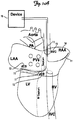
- FIGS. 1A and 1B these field configurations can be achieved by placing several implantable defibrillation electrodes 11 into the proximal 12 and distal 13 coronary sinus ("CS"), the right atrial appendage ("RAA") 14, and the superior venae cavae ("SVC") 15.
- CS coronary sinus
- RAA right atrial appendage
- SVC superior venae cavae
- a right ventricular lead is positioned as part of the implantation ( FIG. 1B ).
- no ventricular lead is positioned ( FIG. 1A ), removing the need to cross a heart valve during lead implantation.
- Leads may be active or passive fixation. As can be seen from FIG. 1 , no leads are placed in the left side of the heart, thus reducing the time required for implantation.
- Electric fields can be delivered between any two of these electrodes as well as between one of these electrodes and the device itself 16 (hot can configuration). Modulation of the electric field vector can be used to achieve maximum coverage of the entire atria and to maintain optimal Virtual Electrode Polarization pattern through the entire cycle of arrhythmia in order to depolarize the maximum area of excitable gaps.
- the optimal electric fields used and the correct sequence of fields can also be explored on a trial and error basis for each patient or can be estimated based on external information regarding potential sites of the reentrant circuits, or can be based on a combination of both.
- each shock can be comprised of a train of electrical pulses.
- multiple, monophasic shocks can be applied with intervals as a function of arrhythmia cycle length.
- the far field unpinning shocks can be square waves, 10 ms in duration of which the voltage and vectors will be varied to determine minimum termination voltage.
- the far field unpinning shocks or pulses may be rounded, staggered, ascending, descending, biphasic, multiphasic or variations thereof.
- a first far field unpinning shock 40 is applied between the electrode located in the right atrial appendage (b) and the device (a).
- a second far field unpinning shock 42 is applied between the electrode located distal in the coronary sinus (e) and the electrode located in the superior venae cavae (c).
- a third far field unpinning shock 44 is applied between the device (a) and the electrode located proximal in the coronary sinus (d).
- An algorithm may be used for treatment of AFl and AF.
- the device can first estimate the CL of arrhythmia. For example, if the average atrial cardiac CL is less than 250 ms, but greater than 150 ms, the atria are considered to be in AFl.
- the distinguishing characteristics of AF and AFl vary on a patient-to-patient basis and thus these CL parameters can be programmable based on patient's need. Examples of distinguishing AF from AFl are described in U.S. Pat. No. 5,814,081 .
- an algorithm can be used to characterize and categorize morphologies of atrial electrogram in order to use this information for patient-specific and morphology-specific optimization of phased unpinning far-field therapy.
- An optimum time to apply the phased unpinning far-field therapy relative to the cardiac cycle may be determined from the ventricular sensing electrodes including RV or far-field R-wave detection. Examples of finding unsafe times for far-field shock are also described in U.S. Pat. No. 5,814,081 .
- therapy can be optimized using a trial and error approach combined with learning algorithms to tailor therapy for each patient.
- the optimization includes two objectives: (a) terminating arrhythmia and (b) avoiding intensities associated with pain.
- the pain threshold depends on many factors, including autonomic tone, presence of drugs, location of electrodes and shock waveforms.
- a value of 0.1 J has been reported by Ladwig, K. H., Marten-Mittag, B., Lehmann, G., Gundel, H., Simon, H., Alt, E., Absence of an Impact of Emotional Distress on the Perception of Intracardiac Shock Discharges, International Journal of Behavioral Medicine, 2003, 10(1): 56-65 , as the energy value where pain and/or discomfort is first generally experienced.
- it can be different from patient to patient.
- a real-time feedback to the patient can be provided in estimating the pain threshold during either the implantation or calibration of the device or during execution of the optimizing learning algorithms.
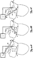
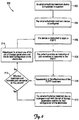
- An atrial arrhythmia treatment device is implanted in a patient, who is sedated or under anesthesia, during a surgical procedure 202.
- the implanted device includes an implantable therapy generator and at least two leads operably connected to the implantable therapy generator, each lead having at least two electrodes adapted to be positioned proximate the atrium of a heart of the patient.
- the atrial arrhythmia treatment device is configured 204.
- the device is instructed to apply a PUFFT treatment 206, via a far field configuration of the electrodes, to the patient in response to detection of an atrial arrhythmia, the PUFFT treatment having a first set of therapy parameters.
- the patient then provides an indication of pain sensation in response to the PUFFT 208.
- An assessment is made of the effectiveness of the PUFFT treatment of the atrial arrhythmia 210.
- An evaluation is made regarding the effectiveness of the PUFFT treatment and the indication of pain sensation 212.
- an adjustment is made to at least one of the set of therapy parameters and the far field configuration of the electrodes 214.
- Steps 206 to 212 are repeated until a set of therapy parameters and a far field configuration of the electrodes have been determined that provide an effective treatment of the atrial arrhythmia for the patient at a pain sensation that is tolerable to the patient.
- the atrial arrhythmia treatment device is then programmed with the set of therapy parameters and the far field configuration of the electrodes 216 as determined from steps 206-214 to be used by the device in automatically treating an atrial arrhythmia detected by the device.
- P101-P103 upon device implantation, several measurements are first made (P101-P103).
- the field excitation thresholds for both atrial and ventricular excitation are measured from each lead combination as described previously (P101). These values serve as the minimum and maximum stimulation strengths, respectively, and can be tested periodically by the device for changes. Stimulation strengths can also be increased until the patient senses the shock and feels pain.
- a patient feedback mechanism can be employed to register this maximum shock amplitude, which corresponds to pain threshold for this particular site.
- the device After implantation, the device enters a sensing mode (21) to sense for atrial tachyarrhythmias.
- the minimum AFl/AF CL can be determined from all sensing electrodes.
- the minimum AFl/AF CL can then be used to calculate the stimulus frequency (23b), which may range from about 20% to about 99% of the minimum AFl/AF CL.
- the device determines if the arrhythmia is the first bout of AFl/AF after implantation (24). If so, a default combination of stimulus parameters combined with the minimum stimulation strengths as previously measured can be used for the first defibrillation trial (P103) and (26).
- the combination of stimulus parameters (23) can include: number of stimuli (23a), frequency of stimuli (23b), number of electric field configurations (23c), sequence of electric field configurations (23d), field strength (23e), waveform morphology (23f), and the inter-stage delay.
- the default combination of parameters can be based on experimental evidence found in animal models of AFl/AF, previous experience with this technology, or results of patient specific testing at the time of implant. If it is not the first bout of AFl/AF after implant, stored parameters from the previous stimulus application can be used for the first defibrillation trial (25)-(26). To avoid inducing a ventricular arrhythmia, the device then waits for the next sensed R-wave to deliver the atrial defibrillation therapy. The appropriate stimulus parameters are then delivered (28).
- sensing can then be employed again to determine if the trial was successful (29). If the trial was unsuccessful, and the duration of AFl/AF has not exceeded the maximum allowed duration (30), the stimulus parameters (23) are varied and another defibrillation trial can be performed (25)-(29). Because of the large number of stimulus parameters (23), a neural network can be employed within the device to control the sequence and optimization of the parameters. The defibrillation trials continue (25)-(29) until the arrhythmia is terminated or until the maximum duration of AFl/AF is reached (30).
- AFl/AF can promote pathological remodeling of atria (atrial fibrillation begets atrial fibrillation), blood clotting and increase a patient's risk of stroke along with other complications, a higher energy rescue shock (31) can be delivered if necessary and low energy optimization can be continued upon the next bout of AFl/AF.
- the stimulus parameters can be saved (36), (25) and employed upon the next bout of AFl/AF. If a particular combination of stimulus parameters is found to be successful for many bouts of AFl/AF (i.e., >5 successful terminations) (33), the device can enter a "continual optimization algorithm" (34) to determine if the energy can be further decreased. The stimulus parameters can be varied at a lower energy (35), (23) to try to find another successful combination. If another such combination is not determined, the device can return to using the successful combination.
- the morphology of an arrhythmia's electrogram can be documented, stored, and compared to previously stored morphologies.
- Anatomic location(s) of the reentry circuit(s) are determined by the specific anatomy and physiological remodeling of the atria, which are unique for each patient.
- the morphologies can reveal the specific anatomic locations of the reentry circuits. Optimization of the pulse sequence of the therapy can be conducted separately for each electrogram morphology and stored in memory for future arrhythmia terminations.
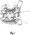
- a default therapy sequence can be initiated for reentry circuits located in each zone. For example, if the morphology of the arrhythmia indicates that the reentry circuit is located in zone 310, the sequence of electric fields applied might begin between electrode (b) and electrode (a) (on the device) as depicted in FIG. 5A . The sequence may then continue with an electric field between electrode (e) and electrode (c) ( FIG. 5B ) followed by one between electrode (a) and electrode (d) ( FIG.
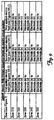
- the table in FIG. 9 provides one example of potential default therapy sequences for each zone 310, 320, 330, 340, and 350 in FIG. 7 . If the default therapy sequence in a given zone fails to terminate the arrhythmia, additional therapy sequences may subsequently be applied.
- this device in certain embodiments, can deliver a series of electric field stimuli in rapid succession
- traditional implantable pulse generators such as those normally used in ICDs generally may be inadequate for the device.
- Traditional implantable pulse generators employ a charging period (on the order of seconds) to charge a capacitor, then rapidly discharge the capacitor to apply the shock. Before the next shock application, the capacitor may need to be charged again.
- several low energy far field unpinning shocks two-ten can be applied in rapid succession (only 10-100 ms apart) for each unpinning shock.
- the implantable pulse generator can include several smaller capacitors that charge before or during the defibrillation trials. For each stimulus delivered, a single capacitor discharges with the appropriate amount of energy followed sequentially by a discharge from another capacitor until the appropriate number of stimuli is delivered.
- the capacitors can all be charged simultaneously before the entire defibrillation trial or, alternatively, the capacitors can be charged sequentially in groups, or individually.
- capacitors which are used for unpinning shocks that appear later in the defibrillation trial are charged while other unpinning shocks are applied earlier in the trial via other capacitors, which were charged previously.
- a capacitor that is used for an earlier unpinning shock is re-charged during a subsequent one or more shock of the trial, and is further re-used for a later unpinning shock of the same trial.
- the power supply is capable of sufficient current drive to charge the capacitors in sufficient time to permit their re-use within the same trial.
- the device uses multiple capacitors for storing the electrotherapy energy, except that, unlike the example embodiment described above, each capacitor has sufficient energy storage to provide more than a single shock in the sequence.
- a fast switching network can be employed to switch the discharged energy between the different capacitors as well as switching the applied energy to the correct electrodes.
- the pretreatment of pulses is described further in U.S. Pat. Nos. 5,366,485 and 5,314,448 .
- RA and LA right and left atria
- PV pulmonary vein
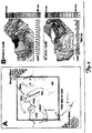
- the fluorescent optical mapping of the posterior atria during ACh-induced AFl and AF in a Langendorff perfused rabbit heart with a photodiode array optical mapping field of view is shown wherein (1) the location of the origin of a normal sinus rhythm heart beat is indicated by a blue/purple circle, (2) the narrow gray oval indicates the line of intercaval conduction block, as identified during normal sinus rhythm and during pacing, the site of resistive heterogeneity, which is highly likely to serve as a pinning site for a reentry circuit during atrial flutter or atrial fibrillation, (3) dashed black lines with arrows indicate the location and direction of reentrant circuits, and (4) dashed white lines indicate vessels that have been ligated.
- FIG. 3B the activation maps and optical action potentials (OAP) during AFL and AF of FIG. 3A are shown, wherein (1) the narrow gray oval indicates the line of intercaval conduction block, the site of resistive heterogeneity, and (2) dashed white lines with arrows indicate the location and direction of reentrant circuits, and wherein isochronal maps are depicted in 4.0 ms steps
- Arrhythmias were provoked by a single premature stimulus or burst pacing.
- Low-energy shocks were delivered from two large mesh electrodes located on either side of the heart, oriented parallel to the vertical axis of the heart.
- Blebbistatin (BB) was used.
- BB is a highly specific inhibitor of myosin TI isoforms.
- ACh depressed the sinus rhythm and provoked atrial premature beats ("APBs") with a coupling interval of 93.+-.7 ms from the RA appendage, superior PVs and inferior vena cava regions.
- APBs resulted in spontaneous AF in 3 hearts.
- a single premature stimulus or burst pacing induced sustained AFl and AF (>10 min) at 7.+-.2 .mu.M and 20.+-.8 .mu.M ACh, respectively.
- AF was associated with mother rotor microreentry in the pectinate muscles of RA (75%) and/or LA (25%).
- FIG. 3B depicts an example of activation during AF.
- AF was associated with a stable mother rotor (figure-of-eight) in the RA appendage. Rarely, several complete rotations of an additional rotor were observed in the LA, but this rotor was generally not sustained.
- a statistically significant phase window was found in which single shocks terminated AFl with a defibrillation threshold (DFT) of 0.9.+-.0.4 V/cm. Termination of AFl was preceded by a short ( ⁇ 1 sec) run of AF in 30% of cases, which are demonstrated examples of destabilization of reentry before its complete termination. Multiple shocks had lower termination strength of 0.7.+-.0.1 V/cm. ATP alone terminated AFl in only 4 of the 6 hearts on which it was applied with 15% of terminations preceded by AF and 11% of applications resulting in sustained AF. Conventional time-independent monophasic shocks terminated sustained AF with a minimum strength 4.7.+-.0.9 V/cm only. The lower efficacy of ATP suggests that low-energy field stimulation may be an alternative to ATP for the treatment of AFl.
- DFT defibrillation threshold
- FIG. 4A shows a preparation of fluorescent optical mapping of the right atrial endocardium during ACh-induced AFl and AF in the canine isolated atria with a photodiode array optical mapping field of view, wherein (1) the sin .theta.-atrial node, which is a resistive heterogeneity, and often serves as a pinning location for a reentry circuit during atrial flutter is indicated by a dark blue/purple oval, (2) dashed white lines with arrows indicate a reentry circuit during atrial flutter, and (3) dashed black lines with arrows indicate a reentry circuit during atrial fibrillation (which is pinned to another resistive heterogeneity).
- FIG. 4B shows activation maps and OAPs during AFL and AF wherein (1) dashed white lines with arrows indicate a reentry circuit during atrial flutter, and (2) dashed black lines with arrows indicate a reentry circuit during atrial fibrillation (which is pinned to another resistive heterogeneity). It can be seen that AF reentry cores were located at functional and anatomical heterogeneities in the pectinate muscles and SVC/IVC regions. Single or multiple monophasic 10 ms shocks were applied from parallel mesh electrodes in the tissue bath using the rabbit experimental setup.
- the far-field diastolic threshold of excitation was reached at 0.14.+-.0.12 V/cm (0.005+0.0001 J) when supra-threshold virtual cathodes were induced at local resistive heterogeneities.
- Single-shock ADFT was significantly lower for AFl vs. AF (0.2.+-.0.06 vs. 7.44.+-.3.27 V/cm, or 0.018.+-.0.001 vs. 2.6.+-.0.78 J; p ⁇ 0.05).
- Atrial defibrillation is best achieved by a two step process: (a) conversion of AF to AFL, and (b) termination of AFl. Both steps are achieved with multiple pulses with energy ranging from 0.02-0.1 J.
- the methods above may be accomplished by an internal, implanted device.
- the methods above may be accomplished using any number and configuration of electrode arrangements, such as endocardial, epicardial, intravenous, implantable or external, or any combination thereof, to deliver electrical cardiac stimulation.
- Multiple path electrode configurations as contemplated for use with some embodiments of the present as shown, for example, in U.S. Pat. Nos. 5,306,291 and 5,766,226 ,.
- the method can be utilized together with, or separate from, other pacing and defibrillation therapies.
- it can be implemented as part of an ICD where a high voltage defibrillation shock can be delivered in the event that the method described above is unable to successfully convert a cardiac arrhythmia.
- a conventional pacemaker to provide for an emergency response to a VT/VF condition in the patient that would increase the chances of patient survival.
- the present invention contemplates the use of an ascending ramp waveform as described in the article Qu, F., Li, L., Nikolski, V. P., Sharma, V., Efimov, I. R., Mechanisms of Superiority of Ascending Ramp Waveforms: New Insights into Mechanisms of Shock-induced Vulnerability and Defibrillation, American Journal of Physiology--Heart and Circulatory Physiology, 2005, 289: H569-H577 .
- phased unpinning far field electrical stimulation pulse(s) may be utilized to generate the lower energy stimulation pulse(s).
- alternative arrangements could be utilized involving lower voltage capacitor arrangements, such as stacked, switched or secondary capacitors, rechargeable batteries, charge pump and voltage booster circuits as described, for example, in U.S. Pat. Nos. 5,199,429 , 5,334,219 , 5,365,391 , 5,372,605 , 5,383,907 , 5,391,186 , 5,405,363 , 5,407,444 , 5,413,591 , 5,620,464 and 5,674,248 .
- Generation of the phased unpinning far field therapy can be accomplished by any number of methods, including known methods for generating pacing pulses. Similarly, any number of known techniques for cardiac arrhythmia detection may be used.
- the PUFFT therapy can be delivered as part of a three-stage atrial cardioversion therapy.
- the therapy (28) that is delivered by the method shown in FIG. 2 comprises a three-stage atrial cardioversion therapy delivered to the patient in response to detection of an atrial arrhythmia, the three-stage atrial cardioversion therapy having a set of therapy parameters and having a first stage (400) and a second stage (402) delivered via a far field configuration of the electrodes and a third stage (404) delivered via a near field configuration of the electrodes.
- a first stage (400) is applied for unpinning of one or more singularities associated with an atrial arrhythmia.
- a second stage (402) is applied for anti-repinning of the one or more singularities associated with the atrial arrhythmia.
- a third stage (404 is applied for extinguishing of the one or more singularities associated with the atrial arrhythmia.
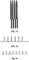
- the first stage (400) has at least two and less than ten biphasic atrial cardioversion pulses of more than 10 volts and less than 100 volts with a pulse duration of approximately 3-4 milliseconds in some examples, or, more generally, of less than 10 milliseconds in various other examples, and a pulse coupling interval of between 20 to 50 milliseconds.
- the first stage (402) has a total duration of less than two cycle lengths of the atrial arrhythmia and is delivered within a ventricular refractory period with an energy of each biphasic atrial cardioversion pulse less than 0.1 joules.
- An interstage delay (I1) of between 100 to 400 milliseconds precedes the second stage (402).
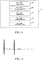
- the second stage (402) has at least five and less than ten far field pulses of less than ventricular far-field excitation threshold (10 volts) with a pulse duration of more than 5 and less than 20 milliseconds and a pulse coupling interval of between 70-90% of the cycle length of the atrial arrhythmia.
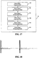
- the third stage (404) has at least five and less than ten near field pulses of less than 10 volts with a pulse duration of more than 0.2 and less than 5 milliseconds and a pulse coupling interval of between 70-90% of the cycle length of the atrial arrhythmia.
- the three-stage atrial cardioversion therapy is delivered in response to detection of the atrial arrhythmia with each stage (400, 402 and 404) without confirmation of conversion of the atrial arrhythmia until after delivery of the third stage (404).
- each of four biphasic cardioversion pulses is delivered from a separate output capacitor arrangement where an H-bridge output switching arrangement reversals the polarity of the far-field electrodes at some point during the discharge of the output capacitor arrangement.
- few output capacitor arrangements may be used where later cardioversion pulses are delivered from the same output capacitor arrangement that was used to delivery an earlier cardioversion pulse and that has been recharged before the later cardioversion pulse.
- each phase of the biphasic cardioversion pulse may be delivered from a separate output capacitor arrangement.
- a switching capacitor network may be used to combine output capacitor arrangements to deliver the cardioversion pulses of the first stage (400).
- the initial output voltage, reversal voltage, duration and coupling interval between pulses may be the same or different for all or for some of the pulses within the range of pulse parameters provided for the first stage (400). It will also be understood that the pulses shown in FIG. 12 of the first stage (400) may all be delivered through the same far-field electrode configuration, and in other examples the pulses may be delivered as part of a rotating set of PUFFT pulses delivered through different far-field electrode configurations.
- each of six monphasic far-field low voltage pulses are delivered from the same output capacitor arrangement that is recharged between successive pulses, although the pulses may each be delivered from separate output capacitor arrangements or from fewer output capacitor arrangements than the total number of pulses in the second stage (402). Alternatively, the pulses may be delivered directly from a charge pump, voltage booster or other similar kind of charge storage arrangement powered by a battery system.
- the initial output voltage, duration and coupling interval between pulses of the second stage (402) may be the same or different for all or for some of the pulses within the range of pulse parameters provided for the second stage (402).
- the pulses shown in FIG. 13 of the second stage (402) may all be delivered through the same far-field electrode configuration, and in other examples the pulses may be delivered as part of a rotating set of PUFFT pulses delivered through different far-field electrode configurations.
- the far-field electrode configuration for the second stage (402) may be the same as, or different than, the far-field electrode configuration utilized for the first stage (400).
- each of eight monophasic near-field low voltage pulses are delivered from the same output capacitor arrangement that is recharged between successive pulses, although the pulses may each be delivered from separate output capacitor arrangements or from fewer output capacitor arrangements than the total number of pulses in the third stage (404).
- the pulses may be delivered directly from a charge pump, voltage booster or other similar kind of charge storage arrangement powered by a battery system.
- the same output capacitor arrangement is used to deliver the second stage pulses and the third stage pulses.
- the initial output voltage, duration and coupling interval between pulses of the third stage (404) may be the same or different for all or for some of the pulses within the range of pulse parameters provided for the third stage (404). It will also be understood that the pulses shown in FIG. 14 of the third stage (404) may all be delivered through the same near-field electrode configuration, and in other examples the pulses may be delivered as part of a rotating set of PUFFT pulses delivered through different near-field electrode configurations. In some examples, the near-field electrode configuration may be a monopolar electrode arrangement, and in other examples, the near-field electrode configuration may be a bipolar electrode arrangement.
- the unpinning stage 1 (400) and anti-repinning stage 2 (402) are each repeated in sequence as part of the overall atrial cardioversion therapy (28) before delivery of the extinguishing stage 3 (404).
- the parameters for each of the stages, and each of the pulses within each stage may be the same or different for different stages and/or different pulses within each stage.
- the unpinning stage 1 (400) and anti-repinning stage 2 (402), as well as the extinguishing stage 3 (404) are each repeated in sequence as part of the overall atrial cardioversion therapy (28), followed by a repeated delivery of all three of the stages before completion of the atrial cardioversion therapy (28).
- the parameters for each of the stages, and each of the pulses within each stage may be the same or different for different stages and/or different pulses within each stage.
- an atrial arrhythmia treatment apparatus 500 includes a plurality of electrodes 502 adapted to be implanted proximate an atrium of a heart of a patient to deliver far field pulses and a plurality of electrodes 504 adapted to implanted proximate the atrium of the heart of the patient to deliver near field pulses and sense cardiac signals.
- the housing of apparatus 500 can serve as one of the far-field electrodes 502 or near-field electrodes 504.
- An implantable therapy generator 506 is operably connected to the electrodes and includes a battery system 508 (or other suitable on-board energy source such as super capacitors, for example) and one or more power supply circuits 510 operably coupled and providing power to sensing circuitry 512, detection circuitry 514, control circuitry 516 and therapy circuitry 518 of the implantable therapy generator.
- therapy circuitry 518 includes a specialized power supply that is fed directly from battery system 508, bypassing power supply circuitry 510.
- Sensing circuitry 512 senses cardiac signals representative of atrial activity and ventricular activity.
- Detection circuitry 514 evaluates the cardiac signals representative of atrial activity to determine an atrial cycle length and detect an atrial arrhythmia based at least in part on the atrial cycle length.
- Control circuitry 516 in response to the atrial arrhythmia, controls generation and selective delivery of a three-stage atrial cardioversion therapy to electrodes 502 and 504, with each stage having an inter-stage delay of between 100 to 400 milliseconds and without confirmation of conversion of the atrial arrhythmia during the three-stage atrial cardioversion therapy.
- detection circuitry 514, control circuitry 516 and therapy circuitry 518 can share components.
- a common microcontroller can be a part of detection circuitry 514, control circuitry 516 and therapy circuitry 518.
- the therapy circuitry 518 is operably connected to electrodes 502 and 504 and control circuitry 516.
- FIG. 19B illustrates an example arrangement of therapy circuitry 518 according to one type of embodiment.
- Therapy circuitry 518 can include its own power supply circuit 602, which is fed from battery system 508.
- Power supply circuit 602 can be a simple voltage regulator, or it can be a current limiting circuit that functions to prevent therapy circuitry (which has the greatest power demands of all the circuitry in the device) from drawing too much power and, consequently, causing a drop in the supply voltage below a sufficient level to power the controller and other critical components.
- power supply circuit 602 can be implemented in power supply circuit 510; or, in one type of embodiment, power supply circuit 602 can be omitted entirely, such that charging circuit 604 is fed directly from battery system 508.
- Charging circuit 604 is a voltage converter circuit that produces voltages at the levels needed for the stimulation waveform.
- the input to charging circuit is a voltage at or near the voltage of battery system 508, which in one embodiment is between 3 and 12 volts. Since the stimulation waveform, particularly the first stage, is at a much higher voltage, up to around 100 volts, a boosting topology is used for charging circuit 604. Any suitable boosting circuit may be employed to this end, including a switching regulator utilizing one or more inductive elements (e.g., transformer, inductor, etc.), or a switching regulator utilizing capacitive elements (e.g., charge pump).
- inductive elements e.g., transformer, inductor, etc.
- capacitive elements e.g., charge pump
- FIGs. 20A-20F illustrate various known topologies for voltage boosting circuits that can be utilized as part of charging circuit 604 according to various embodiments.
- FIG. 20A illustrates a basic boost converter topology.
- the boost converter of FIG. 20A utilizes a single inductor indicated at L1 to store energy in each cycle of switch SW. When switch SW closes, inductor L1 is energized and develops a self-induced magnetic field. When switch SW opens, the voltage at the L1-SW-D1 node is boosted as the magnetic field in inductor L1 collapses. The associated current passes through blocking diode D1 and charges energy storage capacitor C out to a voltage greater than input voltage V in .
- FIG. 20B illustrates a flyback converter topology.
- the flyback converter utilizes transformer T1 as an energy storage device as well as a step-up transformer.
- switch SW When switch SW is closed, the primary coil of transformer T1 is energized in similar fashion to inductor L1 of FIG. 20A .
- switch SW opens, the voltage across the primary coil is reversed and boosted due to the collapsing magnetic field in the primary.
- the changing voltages of the primary coil are magnetically coupled to the secondary coil, which typically has a greater number of windings to further step-up the voltage on the secondary side.
- a typical turns ratio for defibrillator signal applications in certain embodiments is Np:Ns of about 1:15, where Np is the number of primary turns and Ns is the number of secondary turns.
- the high voltage across the secondary coil is rectified by the diode and stored in capacitor C out .
- FIG. 20C illustrates a single ended primary inductance converter (“SEPIC”), which offers certain advantages over other power converter topologies.
- SEPIC single ended primary inductance converter
- the SEPIC converter offers an advantage of not requiring significant energy storage in the transformer. Since most of the energy in a transformer is stored in its gap, this reduces the gap length requirement for the transformer.
- Battery voltage is applied at VIN and the switching element is switched at a fixed frequency and a duty cycle that is varied according to feedback of battery current into the power converter and output voltage.
- Voltage from the output of the step up transformer (T1) is rectified by the diode D1 to generate output voltage on C out .
- FIG. 20D illustrates a variation of the SEPIC converter of FIG. 20C .
- the SEPIC topology of FIG. 20D has an additional inductive component (L1).
- the additional inductor L1 can be implemented either discretely, or can be magnetically coupled with the high voltage transformer into a single magnetic structure, as depicted in FIG. 20D .
- FIG. 20E illustrates a Cuk converter topology.
- a Cuk converter comprises two inductors, L1 and L2, two capacitors, C1 and C out , switch SW, and diode D1.
- Capacitor C is used to transfer energy and is connected alternately to the input and to the output of the converter via the commutation of the transistor and the diode.
- the two inductors L1 and L2 are used to convert, respectively, the input voltage source (V i ) and the output voltage at capacitor C out into current sources.
- V i input voltage source
- the ratio of output voltage to input voltage is related to the duty cycling of switch SW.
- inductors L1 and L2 can be magnetically coupled as indicated T1*.
- FIG. 20F illustrates a basic charge pump topology for multiplying the input voltage.
- the example shown is a Cockcroft-Walton multiplying circuit.
- Three capacitors (C A , C B , and C C ), each of capacity C, are connected in series, and capacitor C A is connected to the supply voltage, V DD .
- capacitor C 1 is connected to C A and charged to voltage V DD .
- capacitor C 1 When the switches change position during the next cycle, ⁇ b , capacitor C 1 will share its charge with capacitor C B , and both will be charged to V DD /2 if they have equal capacity. In the next cycle, C 2 and C B will be connected and share a potential of V DD /4, while C 1 is once again charged to V DD . As this process continues for a few cycles, charge will be transferred to all the capacitors until a potential of 3V DD is developed across the output Vout. Additional stages may be added to increase the voltage multiplication.
- pulse energy storage circuit 606 can take various forms. Generally, pulse energy storage circuit has energy storage capacity sufficient to store either all three stages of the atrial cardioversion therapy, or a portion of the therapy's energy, provided that the arrangement of energy storage circuit 606 and charging circuit 604 supports the ability to recharge portions of the energy storage circuit 606 while other portions thereof are discharging or are about to discharge during application of the electrotherapy.
- FIG. 20G illustrates a basic example of energy storage circuit 606, in which there are three separate storage reservoirs for each of the three stages of the electrotherapy. Storage reservoir 606a stores the energy for the first stage; storage reservoir 606b for the second; and 606c for the third. Each storage reservoir can have one, or a plurality of storage elements.
- each storage reservoir has a plurality of storage element groups, with each storage element group individually switchably selectable for charging and discharging.
- the storage elements can take any suitable form, including capacitors of a suitable technology, e.g., electrolytic, tantalum film, ceramic chip, supercap, or the like.
- Storage reservoirs 606a-606c are coupled to charging circuit 604 via selector switch 607.
- Selector switch 607 can be implemented with an analog multiplexer, transmission gates, or any other suitable electronic switching arrangement. Selector switch 607 is controlled by controller circuit 614 in this example.
- wave shaping circuit 608 regulates the application of the electrotherapy by selecting, and controlling the discharging of the energy stored in energy storage circuit 606.
- wave shaping circuit 608 is in the form of a H-bridge topology, as illustrated in FIG. 20G .
- Switches S1-S4 are individually controlled by controller circuit 614.
- the H-bridge topology facilitates steering, or reversing the polarity, of the electrotherapy signals, enabling a biphasic shock to be applied from a single-polarity energy storage reservoir.
- Other forms of switchable coupling are also contemplated for other embodiments.
- a set of analog transmission gates can be used, such that each storage reservoir 606a-606c is individually selectable. In this latter example, separate capacitors of opposite polarity are used for storing the charge for each phase of the biphasic unpinning waveform of the first electrotherapy phase.
- electrode coupling circuit 610 operates to select which of the multiple sets of patient electrodes 612 are coupled to the output of the wave shaping circuit 608.
- Electrode coupling circuit 610 can be implemented in one example embodiment using a set of analog multiplexers that are controlled by controller circuit 614.
- charging circuit 604 and pulse energy storage circuit 606 can be combined into a single circuit 620, such as a charge pump arrangement, in which certain ones of the capacitors are also used for both, building up charge, and storing the pulse energy for the electrotherapy.
- the pulse energy storage circuit 606 can be one and the same circuit, as the wave shaping circuit 608, depicted at 622, such as, for example, where multiple different capacitors are used to store each individual pulse, and where the electrode coupling circuit has the capability to individually select which capacitors are switched in to which electrodes.
- charging circuit 604, pulse energy storage circuit 606, and wave shaping circuit 608 can be combined as a single circuit implementation 624, which can be implemented as a combination of circuits 620 and 622.
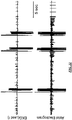
- FIG. 21 illustrates two curves, the top curve showing the signal measured with the EKG lead; and the top curve showing the signal measured with another lead in the atrium.
- the electrotherapy is applied from the RAA to the LAA.
- two unpinning biphasic shocks at 30V with an interval of 40ms are applied.
- eight anti-repinning monophasic shocks at 3V are applied with an interval of 100ms using the same electrodes as those in the first stage.
- FIG. 22 depicts a similar pair of curves, except that the three-stage electrotherapy is applied in three trials.
- the first stage applied has five unpinning biphasic shocks at 20V with an interval of 20ms.
- eight anti-repinning monophasic shocks at 3V with an interval of 100ms are applied from the same electrodes as the first stage.
- eight pacing stimuli with an interval of 100ms are applied from the RA epicardial pacing electrode.
- the second and third trials of the three-stage therapy are applied in similar fashion, except that in the first stage of trials 2 and 3, five unpinning biphasic shocks are applied at 30V with an interval of 20ms.
- the atrial EKG indicates restoration of a normal sinus rhythm following administration of the three trials.
- DFTs of 2BP, 3BP, and 4BP There are no significant difference among DFTs of 2BP, 3BP, and 4BP, while DFT of 4BP is higher than that of 3BP (0.53 ⁇ 0.41 vs. 0.39 ⁇ 0.36 J, ns).
- Atrial flutter (5% cases, which had dominant frequency of 7.7 ⁇ 0.4 Hz) can easily be converted by multiple shocks at 0.0003 ⁇ 0.0001 J. or ATP alone.
Landscapes
- Health & Medical Sciences (AREA)
- Cardiology (AREA)
- Heart & Thoracic Surgery (AREA)
- Life Sciences & Earth Sciences (AREA)
- Radiology & Medical Imaging (AREA)
- Nuclear Medicine, Radiotherapy & Molecular Imaging (AREA)
- Biomedical Technology (AREA)
- Engineering & Computer Science (AREA)
- Animal Behavior & Ethology (AREA)
- General Health & Medical Sciences (AREA)
- Public Health (AREA)
- Veterinary Medicine (AREA)
- Biophysics (AREA)
- Physiology (AREA)
- Electrotherapy Devices (AREA)
Applications Claiming Priority (2)
| Application Number | Priority Date | Filing Date | Title |
|---|---|---|---|
| US12/776,196 US8560066B2 (en) | 2007-12-11 | 2010-05-07 | Method and device for three-stage atrial cardioversion therapy |
| PCT/US2011/033547 WO2011139596A2 (en) | 2010-05-07 | 2011-04-22 | Method and device for three-stage atrial cardioversion therapy |
Publications (3)
| Publication Number | Publication Date |
|---|---|
| EP2566578A2 EP2566578A2 (en) | 2013-03-13 |
| EP2566578A4 EP2566578A4 (en) | 2013-12-04 |
| EP2566578B1 true EP2566578B1 (en) | 2017-12-13 |
Family
ID=44904312
Family Applications (1)
| Application Number | Title | Priority Date | Filing Date |
|---|---|---|---|
| EP11777847.2A Active EP2566578B1 (en) | 2010-05-07 | 2011-04-22 | Device for three-stage atrial cardioversion therapy |
Country Status (10)
| Country | Link |
|---|---|
| US (6) | US8560066B2 (ja) |
| EP (1) | EP2566578B1 (ja) |
| JP (2) | JP5775153B2 (ja) |
| KR (3) | KR101912469B1 (ja) |
| CN (1) | CN103002948B (ja) |
| CA (1) | CA2798956C (ja) |
| ES (1) | ES2661570T3 (ja) |
| HK (1) | HK1182979A1 (ja) |
| IL (1) | IL223432A (ja) |
| WO (1) | WO2011139596A2 (ja) |
Cited By (1)
| Publication number | Priority date | Publication date | Assignee | Title |
|---|---|---|---|---|
| DE102019107117A1 (de) * | 2019-03-20 | 2020-09-24 | Biotronik Se & Co. Kg | Implantierbarer Pulsgenerator für zweistufige Therapie |
Families Citing this family (41)
| Publication number | Priority date | Publication date | Assignee | Title |
|---|---|---|---|---|
| US8175702B2 (en) * | 2004-11-04 | 2012-05-08 | The Washington University | Method for low-voltage termination of cardiac arrhythmias by effectively unpinning anatomical reentries |
| CA2673971C (en) * | 2006-11-13 | 2016-07-19 | Washington University Of St. Louis | Cardiac pacing using the inferior nodal extension |
| US8989860B2 (en) | 2007-03-03 | 2015-03-24 | Max-Planck-Gesellschaft Zur Foerderung Der Wissenschaften E.V. | Multisite heart pacing with adjustable number of pacing sites for terminating high frequency cardiac arrhythmias |
| US20220001189A1 (en) * | 2007-12-11 | 2022-01-06 | The Washington University | Method and device for atrial cardioversion therapy |
| US8560066B2 (en) * | 2007-12-11 | 2013-10-15 | Washington University | Method and device for three-stage atrial cardioversion therapy |
| CN101939044B (zh) * | 2007-12-11 | 2013-12-04 | 圣路易斯华盛顿大学 | 低能量终止心律失常的方法和装置 |
| US8874208B2 (en) * | 2007-12-11 | 2014-10-28 | The Washington University | Methods and devices for three-stage ventricular therapy |
| EP2408521B1 (en) | 2009-03-17 | 2014-06-25 | Cardio Thrive, Inc | External defibrillator |
| US8473051B1 (en) | 2010-12-29 | 2013-06-25 | Cardialen, Inc. | Low-energy atrial cardioversion therapy with controllable pulse-shaped waveforms |
| EP2720751B1 (en) | 2011-06-15 | 2015-04-15 | Max-Planck-Gesellschaft zur Förderung der Wissenschaften e.V. | Apparatus for and method of terminating a high frequency arrhythmic electric state of a biological tissue |
| EP2797665A4 (en) * | 2011-12-30 | 2016-03-16 | Cardialen Inc | NETHERERGETIC FORWARD CARDIOVERSION THERAPY WITH CONTROLLABLE IMPULSE WAVE SHAPES |
| US9510772B2 (en) | 2012-04-10 | 2016-12-06 | Cardionxt, Inc. | System and method for localizing medical instruments during cardiovascular medical procedures |
| US9295850B2 (en) | 2012-04-24 | 2016-03-29 | Medtronic, Inc. | Charge-balancing during electrical stimulation |
| WO2013166485A1 (en) * | 2012-05-04 | 2013-11-07 | The Johns Hopkins University | A method for low voltage defibrillation with far-field stimuli of variable timings based on feedback from the heart |
| US10905884B2 (en) * | 2012-07-20 | 2021-02-02 | Cardialen, Inc. | Multi-stage atrial cardioversion therapy leads |
| US8868178B2 (en) | 2012-12-11 | 2014-10-21 | Galvani, Ltd. | Arrhythmia electrotherapy device and method with provisions for mitigating patient discomfort |
| JP6464145B2 (ja) | 2013-04-05 | 2019-02-06 | ノヴォ・ノルディスク・ヘルス・ケア・アーゲー | 成長ホルモン化合物製剤 |
| EP2796165B1 (fr) * | 2013-04-25 | 2016-04-20 | Sorin CRM SAS | Dispositif médical implantable actif pour le traitement de l'insuffisance cardiaque avec stimulation du nerf vague synchrone à l activité cardiaque |
| US9078583B2 (en) | 2013-08-22 | 2015-07-14 | Aftx, Inc. | Methods, systems, and apparatus for identification and characterization of rotors associated with atrial fibrillation |
| US10279189B2 (en) | 2013-06-14 | 2019-05-07 | Cardiothrive, Inc. | Wearable multiphasic cardioverter defibrillator system and method |
| US10149973B2 (en) | 2013-06-14 | 2018-12-11 | Cardiothrive, Inc. | Multipart non-uniform patient contact interface and method of use |
| US9833630B2 (en) | 2013-06-14 | 2017-12-05 | Cardiothrive, Inc. | Biphasic or multiphasic pulse waveform and method |
| US9616243B2 (en) | 2013-06-14 | 2017-04-11 | Cardiothrive, Inc. | Dynamically adjustable multiphasic defibrillator pulse system and method |
| WO2015017688A2 (en) * | 2013-07-31 | 2015-02-05 | Electus Medical Inc. | Systems for assessing risk of sudden cardiac death, and related methods of use |
| WO2015171492A1 (en) | 2014-05-05 | 2015-11-12 | Cardionxt, Inc. | Methods, systems, and apparatus for identification, characterization, and treatment of rotors associated with fibrillation |
| US9757577B2 (en) | 2014-10-10 | 2017-09-12 | Ruse Technologies, Llc | Method and apparatus for hospital, EMT/EMS, and AED grade external defibrillation and transcutaneous pacing |
| EP3253448B1 (en) * | 2015-02-06 | 2021-02-24 | Cardiac Pacemakers, Inc. | Systems for treating cardiac arrhythmias |
| US20160361555A1 (en) * | 2015-06-10 | 2016-12-15 | Walter T. Savage M.D. | Multivector patient electrode system and method of use |
| JP6482731B2 (ja) * | 2015-09-23 | 2019-03-13 | ウェスト・アファム・ホールディングス・コーポレーションWest Affum Holdings Corp. | 導電性流体用の耐圧容器 |
| US10744334B2 (en) * | 2016-10-18 | 2020-08-18 | Cardiac Pacemakers, Inc. | Systems and methods for arrhythmia detection |
| EP3342455B1 (en) | 2017-01-03 | 2019-06-26 | Max-Planck-Gesellschaft zur Förderung der Wissenschaften e.V. | Apparatus for terminating or unpinning rotating electric activity in a cardiac tissue |
| US10675477B2 (en) | 2018-10-26 | 2020-06-09 | Ruse Technologies, Llc | Implantable cardioverter defibrillators using high power amplifiers with impedance tracking lowpass filters |
| US10967190B2 (en) * | 2018-11-02 | 2021-04-06 | Advanced Neuromodulation Systems, Inc. | Methods of operating a system for management of implantable medical devices (IMDs) using reconciliation operations and revocation data |
| CN111207980B (zh) * | 2020-03-01 | 2022-09-02 | 东北石油大学 | 三层非均质平板岩心压力监测点制作方法 |
| CN111437513B (zh) * | 2020-03-24 | 2023-05-16 | 杭州维纳安可医疗科技有限责任公司 | 多模式高压超短脉冲电场房颤治疗电极及治疗设备 |
| US20230079423A1 (en) * | 2021-09-10 | 2023-03-16 | Cardialen Inc. | Systems, devices, and related methods for cardiac arrhythmia therapy |
| US20220305256A1 (en) * | 2020-12-01 | 2022-09-29 | Cardialen Inc. | Systems, devices, and related methods for cardiac arrhythmia therapy |
| US11484718B2 (en) | 2021-01-22 | 2022-11-01 | Ruse Technologies, Llc | Multimode ICD system comprising phased array amplifiers to treat and manage CRT, CHF, and PVC disorders using ventricle level-shifting therapy to minimize VT/VF and SCA |
| CN116999702A (zh) * | 2021-08-05 | 2023-11-07 | 合源医疗器械(上海)有限公司 | 脉冲刺激装置、方法及医疗设备 |
| WO2023110517A1 (en) * | 2021-12-16 | 2023-06-22 | Biotronik Se & Co. Kg | Implantable cardioverter defibrillator device comprising a shock generation circuitry with a current limiting circuit |
| CN116870365A (zh) * | 2022-01-30 | 2023-10-13 | 合源医疗器械(上海)有限公司 | 脉冲刺激控制方法、装置、医疗系统、电子设备及介质 |
Family Cites Families (118)
| Publication number | Priority date | Publication date | Assignee | Title |
|---|---|---|---|---|
| US543372A (en) * | 1895-07-23 | Emil boettcher of leipsic | ||
| US3605754A (en) | 1967-11-23 | 1971-09-20 | South African Inventions | Double pulse heart defibrillator and method of use |
| US3729008A (en) | 1970-12-28 | 1973-04-24 | American Optical Corp | Electrode for atrial pacing with curved end for atrial wall engagement |
| US3738370A (en) | 1971-01-18 | 1973-06-12 | B Charms | Method of defibrillating a malfunctioning heart by means of electrodes located within the atrium |
| US3942536A (en) | 1971-03-15 | 1976-03-09 | Mieczyslaw Mirowski | Cardioverting device having single intravascular catheter electrode system and method for its use |
| JPS5421286B2 (ja) | 1972-03-22 | 1979-07-30 | ||
| JPS5931221B2 (ja) | 1977-07-19 | 1984-07-31 | 三菱電機株式会社 | 逆導通サイリスタ |
| US4136703A (en) | 1978-03-09 | 1979-01-30 | Vitatron Medical B.V. | Atrial lead and method of inserting same |
| DE2927143A1 (de) | 1978-07-10 | 1980-01-24 | Cordis Corp | Chirurgisches instrument, insbesondere zum annaehen von herzschrittmachern |
| US4384585A (en) | 1981-03-06 | 1983-05-24 | Medtronic, Inc. | Synchronous intracardiac cardioverter |
| US4708145A (en) | 1982-06-01 | 1987-11-24 | Medtronic, Inc. | Sequential-pulse, multiple pathway defibrillation method |
| US4727877A (en) | 1984-12-18 | 1988-03-01 | Medtronic, Inc. | Method and apparatus for low energy endocardial defibrillation |
| US4858623A (en) | 1987-07-13 | 1989-08-22 | Intermedics, Inc. | Active fixation mechanism for lead assembly of an implantable cardiac stimulator |
| US5107834A (en) | 1991-01-30 | 1992-04-28 | Cardiac Pacemakers, Inc. | Low energy multiple shock defibrillation/cardioversion discharge technique and electrode configuration |
| JP3082377B2 (ja) | 1991-02-28 | 2000-08-28 | ソニー株式会社 | 分布定数回路型磁界検出装置 |
| US5407444A (en) | 1992-12-18 | 1995-04-18 | Angeion Corporation | Staged energy concentration for a defibrillator |
| US5383907A (en) | 1992-12-18 | 1995-01-24 | Angeion Corporation | System and method for delivering multiple closely spaced defibrillation pulses |
| US5405363A (en) | 1991-03-15 | 1995-04-11 | Angelon Corporation | Implantable cardioverter defibrillator having a smaller displacement volume |
| US5235979B1 (en) | 1991-03-15 | 1994-11-01 | Angeion Corp | Dual battery system for implantable defibrillator |
| US5433729A (en) * | 1991-04-12 | 1995-07-18 | Incontrol, Inc. | Atrial defibrillator, lead systems, and method |
| US5199429A (en) | 1991-05-23 | 1993-04-06 | Angemed, Inc. | Implantable defibrillator system employing capacitor switching networks |
| US5314448A (en) | 1991-10-28 | 1994-05-24 | Angeion Corporation | Process for defibrillation pretreatment of a heart |
| US5306291A (en) | 1992-02-26 | 1994-04-26 | Angeion Corporation | Optimal energy steering for an implantable defibrillator |
| DE69323310T2 (de) | 1992-04-06 | 1999-09-09 | Angeion Corp | Gerät zur behandlung von herzkammer-tachykardien mittels reihe von entferntenfeld-impulsen |
| US5334219A (en) | 1992-04-09 | 1994-08-02 | Angeion Corporation | Method and apparatus for separate-capacitor cardioversion |
| US5275621A (en) | 1992-04-13 | 1994-01-04 | Medtronic, Inc. | Method and apparatus for terminating tachycardia |
| US6070081A (en) | 1992-10-05 | 2000-05-30 | Ntt Mobile Communications Network, Inc. | Private mobile communication system easily connecting portable or mobile radio telephone equipment to public network |
| US5282836A (en) | 1992-10-23 | 1994-02-01 | Incontrol, Inc. | Atrial defibrillator and method for providing pre-cardioversion pacing |
| US5265600A (en) | 1992-10-23 | 1993-11-30 | Incontrol, Inc. | Atrial defibrillator and method for providing post-cardioversion pacing |
| US5674248A (en) | 1995-01-23 | 1997-10-07 | Angeion Corporation | Staged energy concentration for an implantable biomedical device |
| US5620464A (en) | 1992-12-18 | 1997-04-15 | Angeion Corporation | System and method for delivering multiple closely spaced defibrillation pulses |
| US5792187A (en) | 1993-02-22 | 1998-08-11 | Angeion Corporation | Neuro-stimulation to control pain during cardioversion defibrillation |
| IT1271458B (it) | 1993-03-08 | 1997-05-28 | Leonardo Cammilli | Sistema di stimolazione cardiaca sequenziale (ddd) con l'uso di un elettrocatetere unico inserito attraverso il seno coronarico. |
| US5403356A (en) | 1993-04-28 | 1995-04-04 | Medtronic, Inc. | Method and apparatus for prevention of atrial tachy arrhythmias |
| US5387613A (en) | 1993-07-23 | 1995-02-07 | Ribogene, Inc. | Treatment of tachyarrhythmias of supraventricular origin |
| US5489293A (en) | 1993-08-31 | 1996-02-06 | Ventritex, Inc. | Method and apparatus for treating cardiac tachyarrhythmia |
| US5391186A (en) | 1993-12-13 | 1995-02-21 | Angeion Corporation | Method and apparatus for utilizing short tau capacitors in an implantable cardioverter defibrillator |
| JP3212611B2 (ja) | 1994-04-21 | 2001-09-25 | メドトロニック・インコーポレーテッド | 心房細動を消失させるための植込み可能な医用装置 |
| US5562708A (en) | 1994-04-21 | 1996-10-08 | Medtronic, Inc. | Method and apparatus for treatment of atrial fibrillation |
| US5925066A (en) | 1995-10-26 | 1999-07-20 | Galvani, Ltd. | Atrial arrythmia sensor with drug and electrical therapy control apparatus |
| US5545182A (en) | 1994-09-21 | 1996-08-13 | Intermedics, Inc. | Cardioverter/defibrillator shock timing function |
| US5620469A (en) | 1994-10-11 | 1997-04-15 | Angeion Corporation | Stepped cardioversion system for an implantable cardioverter defibrillator |
| US5658237A (en) * | 1995-08-17 | 1997-08-19 | Medtronic, Inc. | Cardiac assist device having improved muscle stimulation |
| SE9503257D0 (sv) * | 1995-09-20 | 1995-09-20 | Pacesetter Ab | Implanterbar hjärtdefibrillator |
| US5813999A (en) | 1995-12-21 | 1998-09-29 | Incontrol, Inc. | Implantable atrial defibrillator providing reduced cardioversion discomfort |
| US5683429A (en) | 1996-04-30 | 1997-11-04 | Medtronic, Inc. | Method and apparatus for cardiac pacing to prevent atrial fibrillation |
| US6157859A (en) | 1996-05-16 | 2000-12-05 | Sulzer Intermedics, Inc. | Upgradable implantable medical device with post-shock pacing and redraw functions |
| US5645569A (en) | 1996-06-04 | 1997-07-08 | Incontrol, Inc. | Post atrial cardioversion atrial pacing and method |
| US5987354A (en) | 1996-08-13 | 1999-11-16 | Uab Research Foundation | Dual shock atrial defibrillation apparatus |
| US6178351B1 (en) | 1996-08-19 | 2001-01-23 | The Mower Family Chf Treatment Irrevocable Trust | Atrial sensing and multiple site stimulation as intervention means for atrial fibrillation |
| US5797967A (en) | 1996-09-27 | 1998-08-25 | Cardiac Pacemakers, Inc. | System and method to reduce defibrillation requirements |
| US5766226A (en) | 1996-12-09 | 1998-06-16 | Angeion Corporation | Switched discharge pathways for ICD having multiple output capacitors |
| US5840079A (en) | 1997-03-27 | 1998-11-24 | Medtronic, Inc. | Method and apparatus for treatment of atrial fibrillation |
| US5814081A (en) | 1997-04-07 | 1998-09-29 | Incontrol, Inc. | Atrial flutter cardioverter and method |
| US6763266B1 (en) | 1997-05-14 | 2004-07-13 | Pacesetter, Inc. | System and method of generating a low-pain multi-step defibrillation waveform for use in an implantable cardioverter/defibrillator (ICD) |
| US6233483B1 (en) | 1997-05-14 | 2001-05-15 | Pacesetter, Inc. | System and method for generating a high efficiency biphasic defibrillation waveform for use in an implantable cardioverter/defibrillator (ICD). |
| AU8600598A (en) | 1997-07-31 | 1999-02-22 | Case Western Reserve University | Electrolphysiological cardiac mapping system based on a non-contact non-expandable miniature multi-electrode catheter and method therefor |
| US6091991A (en) | 1998-08-07 | 2000-07-18 | Cardicac Pacemakers, Inc. | Method providing atrial anti-tachyarrhythmia therapy |
| US5995871A (en) | 1997-10-29 | 1999-11-30 | Uab Research Foundation | System and method for cardioversion using scan stimulation |
| US5928270A (en) | 1997-12-02 | 1999-07-27 | Cardiocommand, Inc. | Method and apparatus for incremental cardioversion or defibrillation |
| US6085119A (en) | 1998-07-22 | 2000-07-04 | Cardiac Pacemakers, Inc. | Single pass endocardial lead for multi-site atrial pacing |
| US6246906B1 (en) | 1998-03-19 | 2001-06-12 | Cardiac Pacemakers, Inc. | System and method for treating atrial arrhythmias |
| US6556862B2 (en) | 1998-03-19 | 2003-04-29 | Cardiac Pacemakers, Inc. | Method and apparatus for treating supraventricular tachyarrhythmias |
| US6091989A (en) | 1998-04-08 | 2000-07-18 | Swerdlow; Charles D. | Method and apparatus for reduction of pain from electric shock therapies |
| US6094596A (en) | 1998-06-19 | 2000-07-25 | Angeron Corporation | Transvenous defibrillation lead system for use in middle cardiac vein |
| US6141588A (en) | 1998-07-24 | 2000-10-31 | Intermedics Inc. | Cardiac simulation system having multiple stimulators for anti-arrhythmia therapy |
| US6292691B1 (en) | 1998-08-07 | 2001-09-18 | Pacesetter, Inc. | Atrial defibrillation methods and apparatus |
| US6081746A (en) | 1998-08-07 | 2000-06-27 | Pacesetter, Inc. | Atrial defibrillation methods and apparatus |
| US6085116A (en) | 1998-08-07 | 2000-07-04 | Pacesetter, Inc. | Atrial defibrillation methods and apparatus |
| EP1105188B1 (en) | 1998-08-17 | 2005-05-25 | Medtronic, Inc. | apparatus for prevention of atrial tachyarrhythmias |
| US6205357B1 (en) | 1998-12-04 | 2001-03-20 | Uab Research Foundation | Methods and apparatus for detecting and treating medical conditions of the heart |
| US6430438B1 (en) | 1999-05-21 | 2002-08-06 | Cardiac Pacemakers, Inc. | Cardiac rhythm management system with atrial shock timing optimization |
| DE19930266A1 (de) | 1999-06-25 | 2000-12-28 | Biotronik Mess & Therapieg | Katheter |
| IL132036A0 (en) | 1999-09-23 | 2001-03-19 | Univ Ben Gurion | Method and device for the cancellation of unwanted excitation waves in the heart |
| US6810286B2 (en) | 2000-03-06 | 2004-10-26 | Medtronic, Inc | Stimulation for delivery of molecular therapy |
| US6510342B1 (en) | 2000-04-12 | 2003-01-21 | Pacesetter, Inc. | Methods and apparatus for preventing atrial arrhythmias by overdrive pacing multiple heart tissue sites using an implantable cardiac stimulation device |
| US6847842B1 (en) | 2000-05-15 | 2005-01-25 | Cardiac Pacemakers, Inc. | Method and apparatus for reducing early recurrence of atrial fibrillation with defibrillation shock therapy |
| US7069080B2 (en) | 2000-09-18 | 2006-06-27 | Cameron Health, Inc. | Active housing and subcutaneous electrode cardioversion/defibrillating system |
| US6668193B2 (en) | 2001-01-04 | 2003-12-23 | Cardiac Pacemakers, Inc. | Method and apparatus for cardiac shock therapy |
| US6567698B2 (en) | 2001-07-17 | 2003-05-20 | Koninklijke Philips Electronics N.V. | System and method for applying sequential low energy defibrillation pulses |
| US6745081B1 (en) | 2001-08-31 | 2004-06-01 | Pacesetter, Inc. | Coronary Sinus Cardiac Lead For Stimulating and Sensing The Atria of the Right and Left Heart and System |
| US7027876B2 (en) | 2001-10-12 | 2006-04-11 | Medtronic, Inc. | Lead system for providing electrical stimulation to the Bundle of His |
| US7142928B2 (en) | 2001-12-03 | 2006-11-28 | Medtronic, Inc. | Field stimulation about a discontinuity of the myocardium to capture the heart at reduced pacing thresholds |
| US6754525B1 (en) | 2001-12-27 | 2004-06-22 | Pacesetter, Inc. | Reduction of defibrillation requirements through active pre-shock pacing with depolarization verification |
| US6904317B2 (en) | 2002-01-09 | 2005-06-07 | Pacesetter, Inc. | Method and apparatus for dynamically adjusting overdrive pacing parameters |
| US6813516B2 (en) * | 2002-01-31 | 2004-11-02 | Medtronic, Inc. | Method and arrangement for using atrial pacing to prevent early recurrence of atrial fibrillation |
| US6937896B1 (en) | 2002-02-26 | 2005-08-30 | Pacesetter, Inc. | Sympathetic nerve stimulator and/or pacemaker |
| US7027852B2 (en) | 2002-05-21 | 2006-04-11 | Pacesetter, Inc. | Lead with distal tip surface electrodes connected in parallel |
| US7006867B1 (en) | 2002-07-09 | 2006-02-28 | Pacesetter, Inc. | Methods and apparatus for overdrive pacing multiple atrial sites using an implantable cardiac stimulation device |
| US7142927B2 (en) | 2002-09-04 | 2006-11-28 | Uab Research Foundation | Method and system for the selection of cardiac defibrillation shocks based on discomfort |
| US7127292B2 (en) * | 2002-10-31 | 2006-10-24 | Medtronic, Inc. | Addressing recurrent atrial fibrillation |
| US7203538B2 (en) | 2002-11-22 | 2007-04-10 | Cardiac Pacemakers, Inc. | Pacing therapy for extending atrial refractory period |
| US7110811B2 (en) | 2002-12-30 | 2006-09-19 | Cardiac Pacemakers, Inc. | Method and apparatus for atrial tachyarrhythmia cardioversion |
| US7079891B1 (en) | 2003-02-25 | 2006-07-18 | Pacesetter | System and method for providing cardioversion therapy and overdrive pacing using an implantable cardiac stimulation device |
| US7113822B1 (en) | 2003-02-25 | 2006-09-26 | Pacesetter, Inc. | System and method for providing cardioversion therapy and overdrive pacing using an implantable cardiac stimulation device |
| US7047071B2 (en) * | 2003-04-11 | 2006-05-16 | Cardiac Pacemakers, Inc. | Patient stratification for implantable subcutaneous cardiac monitoring and therapy |
| US7139611B1 (en) * | 2003-05-05 | 2006-11-21 | Pacesetter, Inc. | System and method for rejecting far-field signals using an implantable cardiac stimulation device |
| US20050154420A1 (en) | 2004-01-14 | 2005-07-14 | Diaz Cesar M. | System for terminating heart arrhythmia using electrical shocks delivered through a set of internal and external electrodes configurable to a multitude of shock configurations by selecting the shock vector(s) on a control device that also provides "over shock" safety for patients. |
| US7020517B2 (en) | 2004-02-20 | 2006-03-28 | Biophan Technologies, Inc. | Fibrillation/tachycardia monitoring and preventive system and methodology |
| US7155286B1 (en) | 2004-05-26 | 2006-12-26 | Pacesetter, Inc. | System and method for reducing pain associated with cardioversion shocks generated by implantable cardiac stimulation devices |
| US7181276B1 (en) * | 2004-07-27 | 2007-02-20 | Pacesetter, Inc. | Device and method for preventing the acceleration of cardiac arrhythmias |
| WO2006042295A1 (en) | 2004-10-12 | 2006-04-20 | Pressure Products Medical Supplies Inc. | A method and apparatus for atrial wall access and anchoring for pacemaker leads |
| US7650186B2 (en) | 2004-10-20 | 2010-01-19 | Boston Scientific Scimed, Inc. | Leadless cardiac stimulation systems |
| US7532933B2 (en) | 2004-10-20 | 2009-05-12 | Boston Scientific Scimed, Inc. | Leadless cardiac stimulation systems |
| US8175702B2 (en) * | 2004-11-04 | 2012-05-08 | The Washington University | Method for low-voltage termination of cardiac arrhythmias by effectively unpinning anatomical reentries |
| US7471983B2 (en) | 2005-07-19 | 2008-12-30 | Cardiac Pacemakers, Inc. | Pacing output determination based on selected capture threshold values |
| US7480351B2 (en) | 2005-11-07 | 2009-01-20 | Delphi Technologies, Inc. | Technique for demodulating level II hierarchical data |
| ATE493167T1 (de) | 2005-12-09 | 2011-01-15 | Boston Scient Scimed Inc | Herzstimulationssystem |
| US7925343B1 (en) | 2006-10-06 | 2011-04-12 | Pacesetter, Inc. | Subcutaneous implantable cardiac device system with low defibrillation thresholds and improved sensing |
| US7899537B1 (en) | 2006-10-27 | 2011-03-01 | Pacesetter, Inc. | Pericardial cardioverter defibrillator |
| CA2673971C (en) | 2006-11-13 | 2016-07-19 | Washington University Of St. Louis | Cardiac pacing using the inferior nodal extension |
| US20090062877A1 (en) | 2007-03-03 | 2009-03-05 | Valentin Krinski | Multisite heart pacing with adjustable number of pacing sites for terminating high frequency cardiac arrhythmias |
| CN101939044B (zh) | 2007-12-11 | 2013-12-04 | 圣路易斯华盛顿大学 | 低能量终止心律失常的方法和装置 |
| US8560066B2 (en) | 2007-12-11 | 2013-10-15 | Washington University | Method and device for three-stage atrial cardioversion therapy |
| US8874208B2 (en) | 2007-12-11 | 2014-10-28 | The Washington University | Methods and devices for three-stage ventricular therapy |
| EP2229214B1 (en) * | 2007-12-13 | 2016-07-27 | Cardiac Pacemakers, Inc. | Defibrillation shock output circuit |
| EP2254663B1 (en) | 2008-02-07 | 2012-08-01 | Cardiac Pacemakers, Inc. | Wireless tissue electrostimulation |
| US8032218B2 (en) | 2008-07-31 | 2011-10-04 | Pacesetter, Inc. | Implantable cardiac device with satellite refresh |
-
2010
- 2010-05-07 US US12/776,196 patent/US8560066B2/en active Active
-
2011
- 2011-04-22 KR KR1020127032124A patent/KR101912469B1/ko active IP Right Grant
- 2011-04-22 JP JP2013510116A patent/JP5775153B2/ja not_active Expired - Fee Related
- 2011-04-22 KR KR1020197025163A patent/KR102210026B1/ko active IP Right Grant
- 2011-04-22 CN CN201180032063.XA patent/CN103002948B/zh active Active
- 2011-04-22 ES ES11777847.2T patent/ES2661570T3/es active Active
- 2011-04-22 EP EP11777847.2A patent/EP2566578B1/en active Active
- 2011-04-22 CA CA2798956A patent/CA2798956C/en active Active
- 2011-04-22 KR KR1020187030479A patent/KR102018020B1/ko active IP Right Grant
- 2011-04-22 WO PCT/US2011/033547 patent/WO2011139596A2/en active Application Filing
-
2012
- 2012-01-12 US US13/349,517 patent/US8706216B2/en active Active
- 2012-12-04 IL IL223432A patent/IL223432A/en active IP Right Grant
-
2013
- 2013-09-10 HK HK13110460.5A patent/HK1182979A1/xx unknown
-
2014
- 2014-04-21 US US14/257,620 patent/US9289620B2/en active Active
-
2015
- 2015-07-02 JP JP2015133157A patent/JP6193311B2/ja not_active Expired - Fee Related
-
2016
- 2016-02-26 US US15/054,885 patent/US9814895B2/en active Active
-
2017
- 2017-10-09 US US15/727,803 patent/US10441805B2/en active Active
-
2019
- 2019-08-06 US US16/533,355 patent/US11097120B2/en active Active
Non-Patent Citations (1)
| Title |
|---|
| None * |
Cited By (1)
| Publication number | Priority date | Publication date | Assignee | Title |
|---|---|---|---|---|
| DE102019107117A1 (de) * | 2019-03-20 | 2020-09-24 | Biotronik Se & Co. Kg | Implantierbarer Pulsgenerator für zweistufige Therapie |
Also Published As
Similar Documents
| Publication | Publication Date | Title |
|---|---|---|
| US11097120B2 (en) | Method and device for atrial cardioversion therapy | |
| US11083905B2 (en) | Methods and devices for ventricular therapy | |
| EP2231263B1 (en) | Device for low-energy termination of atrial tachyarrhythmias | |
| US20220001189A1 (en) | Method and device for atrial cardioversion therapy | |
| AU2011248794B2 (en) | Method and device for three-stage atrial cardioversion therapy |
Legal Events
| Date | Code | Title | Description |
|---|---|---|---|
| PUAI | Public reference made under article 153(3) epc to a published international application that has entered the european phase |
Free format text: ORIGINAL CODE: 0009012 |
|
| 17P | Request for examination filed |
Effective date: 20121130 |
|
| AK | Designated contracting states |
Kind code of ref document: A2 Designated state(s): AL AT BE BG CH CY CZ DE DK EE ES FI FR GB GR HR HU IE IS IT LI LT LU LV MC MK MT NL NO PL PT RO RS SE SI SK SM TR |
|
| DAX | Request for extension of the european patent (deleted) | ||
| A4 | Supplementary search report drawn up and despatched |
Effective date: 20131105 |
|
| RIC1 | Information provided on ipc code assigned before grant |
Ipc: A61N 1/36 20060101ALI20131029BHEP Ipc: A61N 1/372 20060101ALI20131029BHEP Ipc: A61N 1/05 20060101ALI20131029BHEP Ipc: A61N 1/38 20060101AFI20131029BHEP Ipc: A61N 1/362 20060101ALI20131029BHEP Ipc: A61N 1/39 20060101ALI20131029BHEP |
|
| 17Q | First examination report despatched |
Effective date: 20140623 |
|
| 17Q | First examination report despatched |
Effective date: 20140718 |
|
| STAA | Information on the status of an ep patent application or granted ep patent |
Free format text: STATUS: EXAMINATION IS IN PROGRESS |
|
| GRAP | Despatch of communication of intention to grant a patent |
Free format text: ORIGINAL CODE: EPIDOSNIGR1 |
|
| STAA | Information on the status of an ep patent application or granted ep patent |
Free format text: STATUS: GRANT OF PATENT IS INTENDED |
|
| RIN1 | Information on inventor provided before grant (corrected) |
Inventor name: RIPPLINGER, CRYSTAL, M. Inventor name: EFIMOV, IGOR, R. Inventor name: AMBROSI, CHRISTINA, M. Inventor name: FEDOROV, VADIM, V. Inventor name: FOYIL, KELLEY, V. |
|
| INTG | Intention to grant announced |
Effective date: 20170703 |
|
| GRAS | Grant fee paid |
Free format text: ORIGINAL CODE: EPIDOSNIGR3 |
|
| GRAA | (expected) grant |
Free format text: ORIGINAL CODE: 0009210 |
|
| STAA | Information on the status of an ep patent application or granted ep patent |
Free format text: STATUS: THE PATENT HAS BEEN GRANTED |
|
| AK | Designated contracting states |
Kind code of ref document: B1 Designated state(s): AL AT BE BG CH CY CZ DE DK EE ES FI FR GB GR HR HU IE IS IT LI LT LU LV MC MK MT NL NO PL PT RO RS SE SI SK SM TR |
|
| REG | Reference to a national code |
Ref country code: GB Ref legal event code: FG4D |
|
| REG | Reference to a national code |
Ref country code: AT Ref legal event code: REF Ref document number: 953806 Country of ref document: AT Kind code of ref document: T Effective date: 20171215 Ref country code: CH Ref legal event code: EP |
|
| REG | Reference to a national code |
Ref country code: IE Ref legal event code: FG4D |
|
| REG | Reference to a national code |
Ref country code: DE Ref legal event code: R096 Ref document number: 602011044192 Country of ref document: DE |
|
| REG | Reference to a national code |
Ref country code: ES Ref legal event code: FG2A Ref document number: 2661570 Country of ref document: ES Kind code of ref document: T3 Effective date: 20180402 |
|
| REG | Reference to a national code |
Ref country code: NL Ref legal event code: MP Effective date: 20171213 |
|
| REG | Reference to a national code |
Ref country code: FR Ref legal event code: PLFP Year of fee payment: 8 |
|
| REG | Reference to a national code |
Ref country code: LT Ref legal event code: MG4D |
|
| PG25 | Lapsed in a contracting state [announced via postgrant information from national office to epo] |
Ref country code: LT Free format text: LAPSE BECAUSE OF FAILURE TO SUBMIT A TRANSLATION OF THE DESCRIPTION OR TO PAY THE FEE WITHIN THE PRESCRIBED TIME-LIMIT Effective date: 20171213 Ref country code: NO Free format text: LAPSE BECAUSE OF FAILURE TO SUBMIT A TRANSLATION OF THE DESCRIPTION OR TO PAY THE FEE WITHIN THE PRESCRIBED TIME-LIMIT Effective date: 20180313 Ref country code: FI Free format text: LAPSE BECAUSE OF FAILURE TO SUBMIT A TRANSLATION OF THE DESCRIPTION OR TO PAY THE FEE WITHIN THE PRESCRIBED TIME-LIMIT Effective date: 20171213 Ref country code: SE Free format text: LAPSE BECAUSE OF FAILURE TO SUBMIT A TRANSLATION OF THE DESCRIPTION OR TO PAY THE FEE WITHIN THE PRESCRIBED TIME-LIMIT Effective date: 20171213 |
|
| REG | Reference to a national code |
Ref country code: AT Ref legal event code: MK05 Ref document number: 953806 Country of ref document: AT Kind code of ref document: T Effective date: 20171213 |
|
| PG25 | Lapsed in a contracting state [announced via postgrant information from national office to epo] |
Ref country code: HR Free format text: LAPSE BECAUSE OF FAILURE TO SUBMIT A TRANSLATION OF THE DESCRIPTION OR TO PAY THE FEE WITHIN THE PRESCRIBED TIME-LIMIT Effective date: 20171213 Ref country code: LV Free format text: LAPSE BECAUSE OF FAILURE TO SUBMIT A TRANSLATION OF THE DESCRIPTION OR TO PAY THE FEE WITHIN THE PRESCRIBED TIME-LIMIT Effective date: 20171213 Ref country code: RS Free format text: LAPSE BECAUSE OF FAILURE TO SUBMIT A TRANSLATION OF THE DESCRIPTION OR TO PAY THE FEE WITHIN THE PRESCRIBED TIME-LIMIT Effective date: 20171213 Ref country code: BG Free format text: LAPSE BECAUSE OF FAILURE TO SUBMIT A TRANSLATION OF THE DESCRIPTION OR TO PAY THE FEE WITHIN THE PRESCRIBED TIME-LIMIT Effective date: 20180313 Ref country code: GR Free format text: LAPSE BECAUSE OF FAILURE TO SUBMIT A TRANSLATION OF THE DESCRIPTION OR TO PAY THE FEE WITHIN THE PRESCRIBED TIME-LIMIT Effective date: 20180314 |
|
| PG25 | Lapsed in a contracting state [announced via postgrant information from national office to epo] |
Ref country code: NL Free format text: LAPSE BECAUSE OF FAILURE TO SUBMIT A TRANSLATION OF THE DESCRIPTION OR TO PAY THE FEE WITHIN THE PRESCRIBED TIME-LIMIT Effective date: 20171213 |
|
| PG25 | Lapsed in a contracting state [announced via postgrant information from national office to epo] |
Ref country code: CZ Free format text: LAPSE BECAUSE OF FAILURE TO SUBMIT A TRANSLATION OF THE DESCRIPTION OR TO PAY THE FEE WITHIN THE PRESCRIBED TIME-LIMIT Effective date: 20171213 Ref country code: EE Free format text: LAPSE BECAUSE OF FAILURE TO SUBMIT A TRANSLATION OF THE DESCRIPTION OR TO PAY THE FEE WITHIN THE PRESCRIBED TIME-LIMIT Effective date: 20171213 Ref country code: CY Free format text: LAPSE BECAUSE OF FAILURE TO SUBMIT A TRANSLATION OF THE DESCRIPTION OR TO PAY THE FEE WITHIN THE PRESCRIBED TIME-LIMIT Effective date: 20171213 Ref country code: SK Free format text: LAPSE BECAUSE OF FAILURE TO SUBMIT A TRANSLATION OF THE DESCRIPTION OR TO PAY THE FEE WITHIN THE PRESCRIBED TIME-LIMIT Effective date: 20171213 |
|
| PG25 | Lapsed in a contracting state [announced via postgrant information from national office to epo] |
Ref country code: RO Free format text: LAPSE BECAUSE OF FAILURE TO SUBMIT A TRANSLATION OF THE DESCRIPTION OR TO PAY THE FEE WITHIN THE PRESCRIBED TIME-LIMIT Effective date: 20171213 Ref country code: IS Free format text: LAPSE BECAUSE OF FAILURE TO SUBMIT A TRANSLATION OF THE DESCRIPTION OR TO PAY THE FEE WITHIN THE PRESCRIBED TIME-LIMIT Effective date: 20180413 Ref country code: SM Free format text: LAPSE BECAUSE OF FAILURE TO SUBMIT A TRANSLATION OF THE DESCRIPTION OR TO PAY THE FEE WITHIN THE PRESCRIBED TIME-LIMIT Effective date: 20171213 Ref country code: AT Free format text: LAPSE BECAUSE OF FAILURE TO SUBMIT A TRANSLATION OF THE DESCRIPTION OR TO PAY THE FEE WITHIN THE PRESCRIBED TIME-LIMIT Effective date: 20171213 Ref country code: PL Free format text: LAPSE BECAUSE OF FAILURE TO SUBMIT A TRANSLATION OF THE DESCRIPTION OR TO PAY THE FEE WITHIN THE PRESCRIBED TIME-LIMIT Effective date: 20171213 |
|
| REG | Reference to a national code |
Ref country code: DE Ref legal event code: R097 Ref document number: 602011044192 Country of ref document: DE |
|
| PLBE | No opposition filed within time limit |
Free format text: ORIGINAL CODE: 0009261 |
|
| STAA | Information on the status of an ep patent application or granted ep patent |
Free format text: STATUS: NO OPPOSITION FILED WITHIN TIME LIMIT |
|
| 26N | No opposition filed |
Effective date: 20180914 |
|
| PG25 | Lapsed in a contracting state [announced via postgrant information from national office to epo] |
Ref country code: MC Free format text: LAPSE BECAUSE OF FAILURE TO SUBMIT A TRANSLATION OF THE DESCRIPTION OR TO PAY THE FEE WITHIN THE PRESCRIBED TIME-LIMIT Effective date: 20171213 Ref country code: DK Free format text: LAPSE BECAUSE OF FAILURE TO SUBMIT A TRANSLATION OF THE DESCRIPTION OR TO PAY THE FEE WITHIN THE PRESCRIBED TIME-LIMIT Effective date: 20171213 |
|
| REG | Reference to a national code |
Ref country code: BE Ref legal event code: MM Effective date: 20180430 |
|
| PG25 | Lapsed in a contracting state [announced via postgrant information from national office to epo] |
Ref country code: LU Free format text: LAPSE BECAUSE OF NON-PAYMENT OF DUE FEES Effective date: 20180422 |
|
| PG25 | Lapsed in a contracting state [announced via postgrant information from national office to epo] |
Ref country code: SI Free format text: LAPSE BECAUSE OF FAILURE TO SUBMIT A TRANSLATION OF THE DESCRIPTION OR TO PAY THE FEE WITHIN THE PRESCRIBED TIME-LIMIT Effective date: 20171213 Ref country code: BE Free format text: LAPSE BECAUSE OF NON-PAYMENT OF DUE FEES Effective date: 20180430 |
|
| PG25 | Lapsed in a contracting state [announced via postgrant information from national office to epo] |
Ref country code: MT Free format text: LAPSE BECAUSE OF NON-PAYMENT OF DUE FEES Effective date: 20180422 |
|
| PG25 | Lapsed in a contracting state [announced via postgrant information from national office to epo] |
Ref country code: TR Free format text: LAPSE BECAUSE OF FAILURE TO SUBMIT A TRANSLATION OF THE DESCRIPTION OR TO PAY THE FEE WITHIN THE PRESCRIBED TIME-LIMIT Effective date: 20171213 |
|
| PG25 | Lapsed in a contracting state [announced via postgrant information from national office to epo] |
Ref country code: PT Free format text: LAPSE BECAUSE OF FAILURE TO SUBMIT A TRANSLATION OF THE DESCRIPTION OR TO PAY THE FEE WITHIN THE PRESCRIBED TIME-LIMIT Effective date: 20171213 Ref country code: HU Free format text: LAPSE BECAUSE OF FAILURE TO SUBMIT A TRANSLATION OF THE DESCRIPTION OR TO PAY THE FEE WITHIN THE PRESCRIBED TIME-LIMIT; INVALID AB INITIO Effective date: 20110422 |
|
| PG25 | Lapsed in a contracting state [announced via postgrant information from national office to epo] |
Ref country code: MK Free format text: LAPSE BECAUSE OF NON-PAYMENT OF DUE FEES Effective date: 20171213 |
|
| PG25 | Lapsed in a contracting state [announced via postgrant information from national office to epo] |
Ref country code: AL Free format text: LAPSE BECAUSE OF FAILURE TO SUBMIT A TRANSLATION OF THE DESCRIPTION OR TO PAY THE FEE WITHIN THE PRESCRIBED TIME-LIMIT Effective date: 20171213 |
|
| P01 | Opt-out of the competence of the unified patent court (upc) registered |
Effective date: 20230418 |
|
| PGFP | Annual fee paid to national office [announced via postgrant information from national office to epo] |
Ref country code: IT Payment date: 20230426 Year of fee payment: 13 Ref country code: IE Payment date: 20230419 Year of fee payment: 13 Ref country code: FR Payment date: 20230420 Year of fee payment: 13 Ref country code: ES Payment date: 20230627 Year of fee payment: 13 Ref country code: DE Payment date: 20220620 Year of fee payment: 13 Ref country code: CH Payment date: 20230502 Year of fee payment: 13 |
|
| PGFP | Annual fee paid to national office [announced via postgrant information from national office to epo] |
Ref country code: GB Payment date: 20230419 Year of fee payment: 13 |