EP2565152A1 - Dispositif de formation d'un tuyau flexible de matériau de sachets et procédé de fabrication d'un serpentin de ressorts ensachés - Google Patents
Dispositif de formation d'un tuyau flexible de matériau de sachets et procédé de fabrication d'un serpentin de ressorts ensachés Download PDFInfo
- Publication number
- EP2565152A1 EP2565152A1 EP11007049A EP11007049A EP2565152A1 EP 2565152 A1 EP2565152 A1 EP 2565152A1 EP 11007049 A EP11007049 A EP 11007049A EP 11007049 A EP11007049 A EP 11007049A EP 2565152 A1 EP2565152 A1 EP 2565152A1
- Authority
- EP
- European Patent Office
- Prior art keywords
- cassette
- bag material
- springs
- axis
- Prior art date
- Legal status (The legal status is an assumption and is not a legal conclusion. Google has not performed a legal analysis and makes no representation as to the accuracy of the status listed.)
- Granted
Links
Images


Classifications
-
- B—PERFORMING OPERATIONS; TRANSPORTING
- B68—SADDLERY; UPHOLSTERY
- B68G—METHODS, EQUIPMENT, OR MACHINES FOR USE IN UPHOLSTERING; UPHOLSTERY NOT OTHERWISE PROVIDED FOR
- B68G9/00—Placing upholstery springs in pockets; Fitting springs in upholstery
Definitions
- the invention relates to a device for forming a tube of bag material for producing a pocket spring snake and a method for producing a pocket spring snake.
- the invention relates to such a device and method that can be used in a machine for making a pocket spring snake or a machine for making a pocket spring core to pocket springs.
- Such machines or machines may include a spring former for making springs and a processing station for pocket-loading the springs.
- Other stations may be arranged downstream of the spring former in which the springs, for example, selectively rotated and / or pocket spring snakes can be joined together to form a pocket spring core.
- the number and mode of operation of the downstream of the spring former stations may be different depending on the operation of the respective machine or the respective machine.
- the station for embedding the springs may comprise a cassette with the aid of which a tube of bag material is formed. Springs are inserted into the hose.
- the cassette is conventionally formed with fixed dimensions and may be formed as a one-piece body. Inner dimensions of the cassette are matched to the properties of the springs and / or the pocket material. Examples of such conventional stations for embedding springs are in the US 4,986,518 , of the US 5,553,443 and the US 5,572,853 described.
- the use of the cassette may involve limitations in that it involves only minor variations in the height of the spring to be lipped, the nominal bias of springs, the diameter of feathers to be lipped, or the width of the pocket material allow. This limits the applicability of the station for different spring heights, spring preloads, spring diameters or widths of the pocket material.
- the cassette may be formed as a replacement part.
- a set of different cassettes can be used to accommodate greater variations in spring heights, spring preloads, spring diameters, or widths of bag material. Replacing the cassette is associated with labor, however. Operation of the spring loading station must be interrupted until the replacement of the cassette has been completed.
- an apparatus for forming a tube of bag material comprises a cassette for guiding the bag material.
- the cassette comprises at least a first element and at least a second element.
- the cassette has an axis, a first side defined by the at least one first element, and a second side defined by the at least one second element, wherein the first side and the second side are spaced from one another.
- the apparatus includes an adjustment mechanism coupled to the cartridge and configured to maintain a relative position between the at least one first member and the at least one first member to change a second element in a direction transverse to the axis to adjust a distance between the first side and the second side.
- the device allows adjustment of the inner dimension of the cassette.
- the cassette can be adapted to different spring heights, spring preloads or widths of the pocket material by adjusting a distance between the first side and the second side and thus a width of the cassette transversely to the axis of the cassette.
- the cassette may also allow a change in the height of the cassette to allow for adaptation to different spring diameters or widths of the pocket material.
- the apparatus may be configured to perform the bag material on an inside of the cartridge.
- the bag material may be guided by the device so that it rests against inner sides of the cassette.
- the device may be arranged to perform einutaschende springs on the inside of the cassette. The springs can thus be inserted in the cassette in the tube of bag material.
- the apparatus may be configured to form a rectangular tube of bag material.
- the apparatus may include means for transferring the bag material disposed at one end of the cartridge. By this means for transferring the bag material, the bag material can be folded in the inlet region of the cassette into a tube shape, which is carried out on the inside of the cassette.
- the means for transferring the bag material may comprise at least one projection which projects from the at least one first element or the at least one second element and a folding element with a cavity, wherein the at least one projection projects into the cavity of the folding element.
- An edge of the at least one projection and an edge of the folding element can run along a common straight line or parallel to one another. This allows a displacement of the folding element along the at least one projection, when the distance between the first side and the second side of the cassette is adjusted.
- a cross-sectional area of the cavity of the folding element may be formed as an isosceles triangle.
- a base of the folding element may be formed as an isosceles triangle.
- the at least one first protrusion may comprise a first protrusion protruding from the at least one first element and a second protrusion protruding from the at least one second element. Both the first projection and the second projection may protrude into the cavity of the folding element.
- the first projection may be triangular.
- the second projection may be triangular. A plane in which the first projection and the second projection are located may be inclined relative to the axis of the cassette.
- the at least one first element may comprise a plurality of projections which project into a plurality of corresponding recesses.
- the projections may extend in a direction perpendicular to the axis of the cassette.
- the corresponding recesses may be provided in the at least one second element.
- the corresponding recesses may also be provided in a further element of the cassette, to which the at least one first element is adjustably mounted.
- the cassette may comprise at least a third element extending in a plane perpendicular to the first side and the second side.
- the at least one third element may at least partially cover the at least one first element and the at least one second element.
- the first side and the second side may be opposite inner sides of the cartridge that extend parallel to the axis.
- the cassette may have a rectangular cross section with mutually perpendicular sides. As a result, rectangular tube of bag material can be formed. Corners of the cross section may be rounded at least on the inside of the cassette.
- the at least one first element may comprise a first pair of elements whose relative position is adjustable in a further direction transverse to the axis, the further direction being perpendicular to the axis and to the direction.
- the at least one second element may comprise a second pair of elements whose relative position in the further direction is adjustable transversely to the axis. This makes it possible to make an adjustment both to different spring heights and to different spring diameters.
- the apparatus may include a welder for attaching a weld transverse to the axis.
- the welder is supported so as to be movable relative to the cartridge along a trajectory extending along the axis.
- the trajectory of the welder extends at an angle other than 90 ° relative to the axis of the cartridge.
- the path of movement of the welding device may in particular extend parallel to the axis of the cassette. As a result, the welding device for attaching a transverse seam can also be used for advancing the pocket material.
- the device may comprise a further welding device for attaching a weld seam running along a longitudinal direction of the pocket material.
- the further welder may be arranged to apply the longitudinal weld while the pocket material is being passed through the cassette.
- the cassette may have a recess through which the ends of the pocket material protrude outward to permit attachment of the longitudinal weld.
- the apparatus may include a feeding device for feeding the bag material. This may comprise drive means for driving a roll of bag material.
- the adjustment mechanism can be manually operated. It can also be provided a drive device for driving the adjusting mechanism.
- the adjusting mechanism may be arranged to move both the at least one first element and the at least one second element relative to a holder. This allows a symmetrical adjustment.
- the adjusting mechanism may also be arranged to move only the at least one first element or to move only the at least one second element. This allows a simpler design of the adjustment mechanism.
- the adjusting mechanism may comprise a guide for the at least one first element and / or the at least one second element.
- the guide may extend across the axis of the cassette.
- the adjusting mechanism may comprise a spindle drive to move the at least one first element and / or the at least one second element.
- the adjustment mechanism may be configured to lock a relative position between the at least one first member and the at least one second member when a desired adjustment of the relative position is achieved.
- a system for producing a pocket spring snake comprises a device for forming a tube of bag material according to an embodiment or an embodiment and a device for feeding springs to a cavity defined by the cassette.
- the system may further comprise a spring former.
- a system for producing a pocket spring core comprises a spring former for forming springs, a device for forming a tube of bag material according to an embodiment or an embodiment, means for transferring the springs from the spring former to a cavity defined by the cassette and means for assembling a plurality of pocket spring coils of finite length to a pocket spring core.
- a method for producing a pocket spring coil is specified.
- a cassette comprising at least a first element and at least a second element
- a tube of bag material is formed, are introduced into the springs.
- a relative position between the at least one first member and the at least one second member in a direction transverse to an axis of the cartridge is adjusted to adjust an inner dimension of the cartridge.
- the method allows adjustment of the inner dimension of the cassette.
- the cassette can be adapted to different spring heights, spring diameters, spring preloads or widths of the bag material.
- the relative position may vary depending on a height of the springs, i. the spring dimension along the axial direction of the springs can be adjusted.
- the relative position can be adjusted depending on a spring diameter of the springs.
- the relative position can be adjusted depending on a desired bias of the springs.
- the relative position can be adjusted depending on a width of a band of the bag material.
- the method may be performed using the apparatus for forming a tube of bag material according to an embodiment or an embodiment.
- the devices, systems and methods according to embodiments can be used for embedding springs.
- the springs can be coil springs.
- the springs can be cylinder coil springs.
- the springs may have a diameter that varies along the spring axis.
- the springs can be barrel coil springs.
- the springs may be conical springs, biconical springs or hourglass-shaped springs.
- a device for forming a tube of pocket material or a corresponding method in which a cassette for forming the tube of pocket material is adjustable.
- the cassette has a plurality of elements which are adjustable relative to each other to vary a width and / or height of the cassette perpendicular to a longitudinal axis of the cassette.
- the setting for the cassette used to make a pocket spring snake may be selected depending on a spring height or a desired bias of the springs or a spring diameter of the spring to be lanced.
- the setting for the cassette used to make a pocket spring snake may alternatively or additionally also be selected depending on a width of a web of pocket material into which the springs are to be enclosed.
- the apparatus for forming the tube of bag material may be in a facility for making a pocket spring snake, as described with reference to Fig. 1 or in a plant for making a pocket spring core, as described with reference to Fig. 2 is described.
- Fig. 1 is a schematic representation of a machine 1 for producing a pocket spring snake according to an embodiment.
- the machine 1 comprises a spring-winding device with a wind head 2, a device 3 for transferring the springs from the wind head 2 to a spring conveyor, a spring conveyor designed as a transport wheel 4 with a drive 6 and a station for embedding the springs on a frame 28 of Machine are attached.
- springs formed by the wind head 2 are transferred from the device 3 to the transport wheel 4.
- the transport wheel 4 has a plurality of receptacles 5, in each of which a spring 19 can be received.
- the drive 6 drives the transport wheel 4, wherein the springs cool during transport from the wind head 2 before the pockets of the springs.
- the transport wheel 4 acts as a cooling wheel. In this case, for example, the wire can be heated prior to forming the springs, or a heat treatment of the shaped springs can be made.
- the device 3 for transferring the springs may have a transfer device 11 with a plurality of chamber-like sections 13, 14, in which the transfer device 11 can each receive a spring.
- the transfer device 11 may be movably mounted so that it can be moved between a first and a second position, as shown schematically by the arrow 12. In the first position, the transfer device 11 is arranged so that the first portion 13 receives a spring formed by the wind head 2. In the second position, the transfer device 11 is arranged so that the second portion 14 receives a spring formed by the wind head 2.
- the device 3 for transferring the springs comprises two linearly movable slides 15, 16, which transfer the springs from one of the chamber-like sections 13, 14 to the transport wheel 4. In this case, one of the slides 15, 16 moves into those of the sections 13, 14, in which no spring is being formed.
- the means 3 for transferring the springs may have simpler configurations, in which the springs are transferred by a combination of pivoting element and slide.
- the springs 19 are output from a further transfer device 9, for example one or more pivot levers, from the transport wheel 4.
- the springs are transferred to a device which forms a tube of bag material into which the springs are encapsulated.
- a pocket spring coil 25 is formed with a plurality oftienttaschten springs 26.
- a pocket spring snake 25 is generally a plurality of interconnected pockets referred to therein Lucastaschten springs.
- the apparatus for forming the tube of bag material comprises an adjustable cassette 30 and an adjustment mechanism on, with the cartridge 30 is adjusted depending on a spring size, a desired spring preload or properties of the bag material.
- the bag material 22 is unwound from a roll 21.
- a drive 23 can drive the roller 21 of the bag material.
- the drive 23 can be controlled so that the required material for embedding the springs of the roll 21 is actively handled.
- the pocket material is prefolded by a device 27.
- the pre-folding of the web of bag material 22 may be done so that the web is folded centrally.
- the side of the web of the bag material that becomes the inside of the tube may be disposed on the outside of the pre-folded web.
- the means 27 may comprise a plurality of triangular-shaped elements to pre-fold the web of bag material accordingly.
- the prefolded web is folded over to form an initially open tube 24, which is guided through a cavity defined by the cassette 30.
- Other embodiments are possible to fold the web of bag material into a tube into which the springs are encapsulated.
- the bag material is thermally activatable to allow welding of the tube of bag material.
- the bag material may be, for example, a nonwoven.
- the pocket material can be welded.
- a welding device 32 may be provided, which is arranged downstream of the cassette 30.
- a further welding device 34 may be provided. The further welding device 34 can set the longitudinal seam, while the tube 24 is guided by pocket material and the springs through the cassette 30. To create the longitudinal seam, the longitudinal edges of the pocket material can protrude out of the cassette 30 through a gap.
- a separate transport device can be provided for transporting the bag material and the springs introduced therein.
- a transport of the pocket spring coil 25 in a discharge region of the cassette 30th also be done by the welding device 32 for setting the transverse welds.
- the welding device 32 can be movably mounted along a path 33.
- the web 33 may extend along a longitudinal axis of the cassette 30, that is to say be arranged at an angle other than 90 ° relative to the longitudinal axis of the cassette 30.
- the web 33 along which the welder 32 is moved may extend parallel to the longitudinal axis of the cartridge 30.
- the machine 1 may include a control computer 20.
- the control computer 20 can control the welding devices 32, 34, the drive 23 as well as further elements of the machine 1 automatically. If an adjustment of the cassette 30 is made via an electric drive, the control computer 20 can also control the electric drive for adjusting the cassette 30 in order to adapt the inner dimensions of the cassette.
- the pocket spring coil 25 produced by the machine 1 can be further processed. From the pocket spring snake 25 segments can be separated with a predetermined length and joined together to form a pocket spring core.
- Fig. 2 is a schematic plan view of a system 40 for producing a pocket spring core.
- the plant 40 comprises a machine 1 for making a pocket spring snake, as described with reference to Fig. 1 can be configured described.
- the system 40 has an automatic assembly machine 41 which combines a plurality of pocket spring coils with a predetermined length to form a pocket spring core 44.
- the pocket spring coil is transported by a conveyor 42 to the automatic assembly machine 41.
- a segment 45 of predetermined length can be separated from an endless pocket spring coil using a separator 43.
- Fig. 3 shows a perspective view of an apparatus for forming a tube of the bag material. Also shown is the bag material to better illustrate the transformation from a web to a tube.
- the device has a cassette 30, which is shown offset for reasons of clarity to the bag material.
- the device has a welding device 32 for Generating transverse seams between pockets and another welding device 34 for generating a longitudinal seam.
- the welding device 32 is also shown offset from the bag material for reasons of clarity.
- the cassette 30 has a first element 61 and a second element 62.
- the first element 61 and the second element 62 may be provided with a (in Fig. 3 not shown) adjusting mechanism are adjusted relative to each other to change the inner dimensions of the cartridge 30.
- the cassette 30 has a longitudinal axis 50.
- the adjustment mechanism allows a change in the relative position between the first member 61 and the second member 62 along a width direction 60 of the cartridge 30, which is perpendicular to the longitudinal axis 50. About the adjustment of the distance between the two parallel to the longitudinal axis 50 extending sides of the cassette can be changed, of which the side 64 in Fig. 3 is visible.
- the cartridge 30 has in its inlet region, are supplied to the bag material and springs, means for folding the bag material.
- This means for folding the bag material comprises a first protrusion 65 protruding from the first element 61, a second protrusion 66 protruding from the second element 62, and a folding element 67 for folding the bag material.
- the folding element 67 surrounds the first projection 65 and the second projection 66 at least partially.
- the cassette 30 may comprise further elements.
- a first cover plate part 68 and a second cover plate part 69 may be provided. Through a gap 70 between the cover sheet parts, the two longitudinal edges of the web of pocket material can protrude from the cassette 30. This allows the attachment of a longitudinal seam.
- a position of the first member 61 can be adjusted relative to the first cover sheet member 68 when the width of the cartridge is changed via the adjusting mechanism.
- a position of the second member 62 can be adjusted relative to the second cover sheet member 69 when the width of the cassette is changed via the adjusting mechanism.
- the bag material 22 is folded in an inlet region of the cassette 30 so that a tube is formed, which is initially still open.
- an un-hatched area of the pocket material represents that side of the web which is the outer side the hose forms.
- the hatched area is that side of the web that forms the inside of the tube.
- the web of pocket material 22 may be pre-folded in front of the lead-in area of the cassette 30 along the center of the web.
- the side 52 of the web, which forms the inside of the tube, can be outside.
- a portion 53 of the bag material located in the lead-in area of the cassette 30 is folded over by the folding device and the top edge of the cassette 30 such that the outer surfaces of the supplied prefolded web become the inside of the tube.
- the outer surface of the formed tubing faces the inner surfaces of the cassette 30.
- the longitudinal edges of the web project outwardly through the gap 70 to allow attachment of the longitudinal weld 55.
- Springs 19 are also transported through the cassette 30 where they are inserted into the tube 54.
- the transverse welds 56 are formed after the tube 54 of the bag material with the springs arranged therein has passed a discharge region of the cassette 30.
- Fig. 4 shows a perspective detail view of the lead-in area of the cassette 30.
- a distance 76 can be adjusted between the two inside of the cassette, against which the axial ends of the springs press the bag material.
- the distance 76 can be selected depending on various parameters, in particular depending on a height of the springs, ie the dimension along its axial direction, and depending on a desired spring preload of the pocketed springs.
- the means for folding the bag material may be arranged to automatically adjust its configuration as the width 76 changes.
- the projections 65 and 66 may be triangular.
- the folding element 67 may have a (in Fig. 4 have upward surface), which has the shape of an isosceles triangle.
- the folding element 67 can partially overlap the projections 65 and 66.
- the folding element 67 may be formed as a bent sheet metal part, wherein the projections 65 and 66 protrude into the cavity, which is formed by the folding element 67.
- the outer edges of the projections 65 and 66, over which the bag material is guided may extend parallel to the outer edges of the folding element 67, over which the bag material is guided , or be arranged on a common line with these. Accordingly, the inner edges of the folding element 67, against which abut the outer edges of the projections 65 and 66 on the folding element 67, parallel to the outer edges of the projections 65 and 66 extend or be arranged on a common line with these.
- the bag material exerts a force on the folding element 67 in the direction of the elements 61, 62 of the cassette. If the width 76 of the cassette 30 is changed with the adjusting mechanism, the position of the folding element 67 changes accordingly relative to the elements 61, 62.
- the displacement of the folding element 67 is shown schematically at 77. In this way, a size of a triangular surface, at which the pocket material is folded over at the inlet region of the cassette, can be adapted to the width of the cassette without making a separate adjustment of the device for folding over.
- a leading edge 74 of the first cover sheet member 68 may be parallel to or in line with a leading edge 71 of the first member 61 of the cartridge 30.
- a leading edge 75 of the second cover sheet member 69 may be parallel to or in line with a leading edge 72 of the second member 62 of the cassette 30.
- the leading edges 71, 74 may lie in a plane that is perpendicular to a plane defined by the top of the cartridge 30.
- the leading edges 72, 75 may lie in another plane that is perpendicular to the plane defined by the top of the cartridge 30.
- a coupling may be provided such that the relative position between the first member 61 and the cover plate member 68 and the relative position between the second element 62 and the cover plate part 69 is automatically adjusted during an adjustment of the width of the cassette 30.
- the first element 61 may be coupled to the first cover sheet part 68 such that when the width 76 is adjusted, there is a relative movement 78 between the first element 61 and the cover plate part 68 is caused, which is at least also along the longitudinal axis 50 of the cassette 30 directed.
- the coupling may be such that upon adjustment of the width 76, the relative movement 78 along the longitudinal axis 50 of the cartridge 30 is caused so that the leading edges 71 and 74 remain arranged in a plane perpendicular to that defined by the top of the cartridge 30 Level is.
- the second member 62 may be coupled to the second cover sheet member 69 such that upon adjustment of the width 76, a relative movement 78 between the second member 62 and the cover sheet member 69 is caused, which is also directed at least along the longitudinal axis 50 of the cassette 30.
- the coupling may be such that upon adjustment of the width 76, the relative movement 78 along the longitudinal axis 50 of the cartridge 30 is caused so that the leading edges 72 and 75 remain disposed in another plane perpendicular to that through the top of the cartridge 30 defined level is.
- the first element 61 can have projections which run parallel to the front edge 71.
- the first cover plate part 68 may have corresponding recesses which run parallel to the front edge 74 and in which the projections of the first element 61 engage.
- a similar coupling may be present between the second member 62 and the second cover sheet member 69.
- Fig. 5 shows a schematic cross-sectional view through the apparatus for forming the tube of bag material.
- the cutting plane is chosen to pass through the adjustment mechanism.
- the adjustment mechanism may have various configurations that allow a change in the relative position between the elements 61, 62 and thus a change in the distance between the inner side 63, 64 of the cassette 30.
- the adjustment mechanism may be configured to guide movement of at least one of the members 61, 62 in the width direction 60 of the cartridge 30.
- the adjustment mechanism may be arranged to lock the first member 61 and / or the second member 62 to maintain a set relative position until the adjustment mechanism is actuated again.
- the adjusting mechanism has a first spindle drive coupled to the first element 61 and a second spindle drive coupled to the second element 62.
- the first spindle drive comprises a spindle 84 and a spindle block 85 with a corresponding bore.
- the spindle block 85 is connected to the first member 61.
- the second spindle drive comprises a spindle 86 and a spindle block 87 with a corresponding bore.
- the spindle block 87 is connected to the second member 62.
- the spindles 84, 86 may be manually operable. Alternatively, an actuator, for example an electric motor 89, for driving the spindles 84, 86 may be provided.
- An additional guide may be provided to guide the movement of the first member 61 and / or the second member 62.
- the guide may comprise a guide recess and complementary projections 82, 83.
- the guide recess may for example be provided in a holder 81, which is arranged stationary.
- the projections 82, 83 can each be attached to one of the elements 61, 62.
- only one spindle can be provided, which is coupled to a plurality of spindle blocks 85, 86.
- the spindle drive thus formed can also displace the elements 61, 62 symmetrically relative to a median plane of the cassette 30.
- a change in the relative position between the first member 61 and the second member 62 may be caused by shifting only one of these members.
- a spindle drive is shown, a variety of other mechanisms can be used to change the inner dimensions of the cassette 30.
- a rack and pinion drive can be used.
- a guide may be provided to guide the movement of the first member 61 and / or the second member 62.
- the adjusting device further comprises a locking device for locking the first element 61 and / or the second element 62. The first element 61 and / or the second element 62 can be moved manually along the guide.
- plan view is directed along the longitudinal axis 50 of the cassette 30.
- the projections 65 and 66 are coupled to the folding element 67.
- the folding element 67 is displaceable relative to the projections 65, 66.
- the folding element 67 can at least partially surround the projections 65, 66.
- An edge 91 of the projection 65 is arranged parallel to or in line with an edge 92 of the folding element 67. That the direction vector of the edge 91 coincides with the direction vector of the edge 92.
- an outer edge of the projection 66 is disposed parallel to or in line with another outer edge of the seaming member.
- the folding element 67 is displaced relative to the projections 65, 66.
- the folding element 67 is positioned in the operation of the device so that it is pushed further over the projections 65, 66. This is exemplary in Fig. 7 shown in which the cassette is pushed together to a width 76 '.
- the cassette has a pair of parallel sides 63, 64 and another pair of parallel sides defining the top and bottom of the cavity formed by the cassette.
- the cassette may have a rectangular cross-sectional area, the transitions between the sides being advantageously rounded.
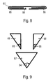
- Fig. 8 is a sectional view taken along the line VIII-VIII in Fig. 7 ,
- the folding element 67 defines a cavity 93 into which the projections 65, 66 protrude.
- the folding element 67 may be formed, for example, as a bent sheet metal part.
- Fig. 9 shows the projections 65, 66 and the folding element 67 in a plan view.
- the folding element 67 may have a (in Fig. 3 and 4 facing upward) surface, which has the shape of an isosceles triangle.
- the leg of equal length include an angle 94.
- the projections 65, 66 may also be triangular.
- An opening angle 95, 96 at that corner of the projections 65, 66, which is encompassed by the folding element 67, may be half the opening angle 94.
- the projections 65, 66 may have the shape of right triangles.
- An embodiment of the device for folding over the bag material as in Fig. 9 allows automatic adjustment up to the width 76 at which the edges of the projections 65, 66 abut each other. In this way, an adjustability over a wide range can be made possible.
- FIG. 10 and 11 show perspective views of an apparatus for forming a tube of bag material according to another embodiment.
- the general operation corresponds to the operation of referring to Fig. 3-9 described apparatus for forming a tube of bag material.
- the device has a cassette 30 with a first element 61 and a second element 62. At least one of the members 61, 62 may be moved relative to a bracket 81 to allow adjustment of the width of the cartridge 30.
- a corresponding adjusting mechanism is provided in order to allow a change in the relative position between the first element and the second element 62.
- the adjusting mechanism may for example comprise at least one spindle drive.
- the adjustment mechanism can be manually or electronically actuated.
- the adjustment mechanism can also be formed by a guide, along which one of the elements 61, 62 or both elements 61, 62 can be moved manually.
- the first element 61 and / or the second element 62 may have a plurality of projections.
- the projections can protrude into corresponding recesses. With a change in the width of the cassette, the projections can move further into or out of the corresponding recesses. The appearance of a over the entire length of the cassette extending gap at the bottom of the cassette 30 can be avoided. This allows a better support of the bag material.
- Fig. 12 shows an enlarged view of the detail XII of Fig. 11 ,
- finger-like projections 103 are arranged in a portion 101 of the first member 61, which is arranged on the underside of the cartridge 30, finger-like projections 103 are arranged.
- a section 102 of the second element 62 which is arranged on the underside of the cassette 30, corresponding recesses 104 are arranged.
- the projections 103 drive out of the recesses 104 or further into this.
- the first member 61 and / or the second member 62 may have a plurality of protrusions or a plurality of recesses.
- the first element 61 may have a plurality of finger-like projections 105 that are coupled with corresponding recesses in a separate cover element 67.
- Each of the projections 105 may be disposed at an angle other than 90 ° to the longitudinal axis of the cartridge 30.
- the projections 105 may in particular be parallel to a front edge of the first element 61 at the inlet region of the cassette.
- the second member 62 may include a plurality of finger-like projections 106.
- the first element 61 on the upper side of the cassette can have recesses in which engage corresponding projections of a cover element 67.
- the apparatus may also be configured to have a height adjustable or such that both the width and the height of the cassette are adjustable ,
- Fig. 13 shows a plan view of an apparatus for forming a tube of bag material according to another embodiment.
- the apparatus comprises a multi-element cassette and an adjustment mechanism which permits adjustment of the width 76 and a height 115 of the cassette.
- a device for folding over the bag material may also be provided, as described with reference to FIG Fig. 3-9 has been described in detail.
- the cassette has a first pair of elements 111, 112.
- the pair of members 111, 112 defines a side surface of the cartridge.
- the element 112 is adjustable relative to the element 111 in a direction 120 which is perpendicular to the longitudinal axis 50 of the cassette and to the width direction 60.
- the cassette has a second pair of elements 113, 114.
- the pair of elements 113, 114 defines another side surface of the cassette.
- the element 114 is adjustable relative to the element 113 in the direction 120, which is perpendicular to the longitudinal axis 50 of the cassette and to the width direction 60.
- the adjustment mechanism is arranged to allow a change in the relative position of the first pair with the members 111, 112 relative to the second pair with the members 113, 114 to adjust a width 76 of the cartridge.
- the adjustment mechanism is arranged to allow a change in a relative position of the member 112 relative to the member 111 of the first pair, and to allow a change in a relative position of the member 114 relative to the member 113 of the second pair. In this way, a height 115 of the cassette can be adjusted. As a result, an adaptation to different spring diameters widths of the web of the pocket material is possible.
- an adjustable cassette may have a plurality of embodiments.
- An adjustable cassette can also be used if the web of bag material is not delivered to the cassette in a pre-folded manner.
- An adjustable cassette can also be used without a separate device for folding the web.
- FIG. 14 Figure 11 is a perspective view of an apparatus 130 for forming a tube of bag material according to another embodiment.
- the device 130 comprises a cassette having a first element 134 and a second element 135, which are mounted on a support element 132.
- the support member 132 is held by a carrier 133.
- the first element 134 and the second element 135 are mounted on the support member 132 so that their relative position can be adjusted perpendicular to a longitudinal axis of the cassette.
- an adjusting mechanism is provided, which comprises, for example, suitable guides on the support element and the elements 134, 135.
- the adjustment mechanism may include a drive for moving one or both elements 134, 135.
- the bag material is folded over at the inlet end of the cassette.
- the delivered web 22 is first guided over a deflection roller 131 along an outer side of the cassette.
- the web of bag material is then pulled into the cassette.
- the web inside the cassette forms a first still open tube 136.
- the longitudinal edges of the web 136 may be overlaid in the cassette to facilitate the attachment of a longitudinal weld.
- the cassette dispenses a tube 137 of bag material having a rectangular cross-section with rounded corners.
- a longitudinal seam 138 may be attached by welding the pocket material.
- Springs 19 are also guided through the cassette and introduced there in the folded to a tube 136 path.
- the device for forming the hose can be designed such that an adjustment to different spring diameters is made by adjusting the at least one first element and the at least one second element.
- the apparatus for forming the tube of bag material can be used not only when the tube abuts the insides of the cassette, but also when the web is folded around an outside of the cassette to form the tube.
- the apparatus for forming a hose may be used as part of an automatic machine that produces a pocket spring coil from spring wire and bag material
- the apparatus for forming the hose may also be used in a separate spring loading machine. This machine, for example, ready-formed springs are supplied, which are then inserted into the tube formed and welded into individual pockets.
- the device for forming the hose can be designed so that an adaptation to different spring heights, spring preloads, spring diameters or widths of the web of the bag material can be made.
- the cassette can also be adjusted depending on which type of spring is to be dipped. For example, a dimension of the cassette can be set depending on whether cylinder springs or barrel springs are to be doused.
- the devices and methods of embodiments can be used in machines for making pocket springs or pocket spring cores, without being limited to this application.
Landscapes
- Engineering & Computer Science (AREA)
- Mechanical Engineering (AREA)
- Making Paper Articles (AREA)
- Containers And Plastic Fillers For Packaging (AREA)
- Air Bags (AREA)
- Auxiliary Devices For And Details Of Packaging Control (AREA)
Priority Applications (6)
| Application Number | Priority Date | Filing Date | Title |
|---|---|---|---|
| EP11007049.7A EP2565152B1 (fr) | 2011-08-30 | 2011-08-30 | Dispositif de formation d'un tuyau flexible de matériau de sachets et procédé de fabrication d'un serpentin de ressorts ensachés |
| PL11007049T PL2565152T3 (pl) | 2011-08-30 | 2011-08-30 | Urządzenie do tworzenia rękawa z materiału kieszeni i sposób wytwarzania rzędu sprężyn kieszeniowych |
| CN201280042118.XA CN103764543B (zh) | 2011-08-30 | 2012-08-02 | 用于形成袋装材料管的装置和制造袋装弹簧串的方法 |
| JP2014526407A JP2014529553A (ja) | 2011-08-30 | 2012-08-02 | ポケット素材の筒を形成する装置及びポケットスプリング列を製造する方法 |
| PCT/EP2012/003306 WO2013029736A1 (fr) | 2011-08-30 | 2012-08-02 | Dispositif pour former un tube de matériau à poches et procédé de fabrication d'un chapelet de ressorts ensachés |
| US14/342,009 US9682852B2 (en) | 2011-08-30 | 2012-08-02 | Apparatus for forming a tube of pocket material and method for manufacturing a pocket spring string |
Applications Claiming Priority (1)
| Application Number | Priority Date | Filing Date | Title |
|---|---|---|---|
| EP11007049.7A EP2565152B1 (fr) | 2011-08-30 | 2011-08-30 | Dispositif de formation d'un tuyau flexible de matériau de sachets et procédé de fabrication d'un serpentin de ressorts ensachés |
Publications (2)
| Publication Number | Publication Date |
|---|---|
| EP2565152A1 true EP2565152A1 (fr) | 2013-03-06 |
| EP2565152B1 EP2565152B1 (fr) | 2014-06-18 |
Family
ID=46639426
Family Applications (1)
| Application Number | Title | Priority Date | Filing Date |
|---|---|---|---|
| EP11007049.7A Active EP2565152B1 (fr) | 2011-08-30 | 2011-08-30 | Dispositif de formation d'un tuyau flexible de matériau de sachets et procédé de fabrication d'un serpentin de ressorts ensachés |
Country Status (6)
| Country | Link |
|---|---|
| US (1) | US9682852B2 (fr) |
| EP (1) | EP2565152B1 (fr) |
| JP (1) | JP2014529553A (fr) |
| CN (1) | CN103764543B (fr) |
| PL (1) | PL2565152T3 (fr) |
| WO (1) | WO2013029736A1 (fr) |
Cited By (1)
| Publication number | Priority date | Publication date | Assignee | Title |
|---|---|---|---|---|
| CN110329981A (zh) * | 2019-07-31 | 2019-10-15 | 浙江华剑智能装备有限公司 | 袋装弹簧生产设备 |
Families Citing this family (9)
| Publication number | Priority date | Publication date | Assignee | Title |
|---|---|---|---|---|
| GB2506104B (en) | 2012-08-10 | 2018-12-12 | Hs Products Ltd | Resilient unit with different major surfaces |
| KR102410333B1 (ko) * | 2015-07-07 | 2022-06-20 | 오씨아이 주식회사 | 포장장치 |
| EP3452373A4 (fr) * | 2016-05-05 | 2019-12-25 | Moda IP Limited | Appareil d'ensacheuse tubulaire |
| US10577240B2 (en) * | 2017-04-17 | 2020-03-03 | Macao Commercial & Industrial Spring Mattress Manufacturer Macao TAIWA Machinery | Automatic bagged spring production apparatus |
| GB201708635D0 (en) | 2017-05-31 | 2017-07-12 | Hs Products Ltd | Pocketed spring unit and method manufacture |
| GB201708639D0 (en) * | 2017-05-31 | 2017-07-12 | Hs Products Ltd | Transportation Apparatus and method |
| US11254455B2 (en) * | 2019-03-18 | 2022-02-22 | The Procter & Gamble Company | Packaging apparatus and method for wrapping absorbent paper product |
| JP7319657B2 (ja) * | 2019-05-23 | 2023-08-02 | 大森機械工業株式会社 | ピロー包装機および通紙方法 |
| CN114176358B (zh) * | 2021-12-31 | 2023-09-05 | 山东恒富家居科技有限公司 | 一种复合床垫弹簧的生产工艺 |
Citations (4)
| Publication number | Priority date | Publication date | Assignee | Title |
|---|---|---|---|---|
| DE624410C (de) * | 1934-04-01 | 1936-01-22 | Emil & Julius Spuehl | Maschine zur Herstellung von mit Sprungfedern gefuellten Taschenbaendern fuer Polster und Matratzen |
| US4986518A (en) | 1988-06-13 | 1991-01-22 | Simmons U.S.A. Corporation | Pocketed coil strings having a flat overlap side seam |
| US5509887A (en) * | 1991-01-03 | 1996-04-23 | Simmons Company | Apparatus for pocketed coil construction having improved tracking characteristics |
| US5553443A (en) | 1994-08-15 | 1996-09-10 | Simmons Company | Method for creating strings of pocketed coil springs |
Family Cites Families (51)
| Publication number | Priority date | Publication date | Assignee | Title |
|---|---|---|---|---|
| US466023A (en) * | 1891-12-29 | button | ||
| US229479A (en) * | 1880-06-29 | Petess co | ||
| US1618711A (en) * | 1923-12-24 | 1927-02-22 | Independent Paper Mills Inc | Paper-folding machine |
| US1574789A (en) * | 1924-12-02 | 1926-03-02 | William R Burgess | Vertical-file-folder machine |
| US1710979A (en) * | 1926-01-18 | 1929-04-30 | Cons Mattress Co | Method and apparatus for making mattresses |
| US3111310A (en) * | 1961-12-21 | 1963-11-19 | Orville V Dutro | Folder |
| GB1022287A (en) * | 1962-05-22 | 1966-03-09 | United States Bedding Co | Method and apparatus for the production of mattresses |
| FR1355409A (fr) * | 1963-05-09 | 1964-03-13 | United States Bedding Co | Procédé et appareil pour la fabrication de matelas |
| US3296770A (en) * | 1965-01-13 | 1967-01-10 | Russell W Wilson | Adjustable package-forming machine |
| US3431828A (en) * | 1965-09-17 | 1969-03-11 | Fmc Corp | Bag stacker |
| US3449190A (en) * | 1966-03-14 | 1969-06-10 | Us Bedding Co The | System for the production of mattress and cushion constructions |
| FR1475098A (fr) * | 1966-03-18 | 1967-03-31 | United States Bedding Co | Procédés de fabrication des coussins et des matelas |
| US3415171A (en) * | 1967-05-10 | 1968-12-10 | Russell W. Wilson | Adjustable package-forming machine |
| US3668816A (en) * | 1970-07-10 | 1972-06-13 | Mildred B Thompson | Method and apparatus for constructing fabric enclosed springs |
| JPS5026679Y2 (fr) * | 1971-11-06 | 1975-08-08 | ||
| DE2657790A1 (de) * | 1976-12-21 | 1978-06-22 | Rovema Gmbh | Schlauchbeutelmaschine |
| US4439977A (en) * | 1977-05-05 | 1984-04-03 | Simmons U.S.A. Corporation | Method and apparatus for making a series of pocketed coil springs |
| US4494362A (en) * | 1981-03-24 | 1985-01-22 | Metromail, Inc. | Package forming web folder |
| US4766716A (en) * | 1987-11-12 | 1988-08-30 | Formers Of Houston, Inc. | Adjustable guide roller assembly for tube forming apparatus |
| US4854023A (en) * | 1988-06-13 | 1989-08-08 | Simmons U.S.A. Corporation | Method for providing pocketed coil strings having a flat overlap side seam |
| US5255495A (en) * | 1992-10-30 | 1993-10-26 | Hayssen Manufacturing Company | Adjustable girth former |
| GB9301927D0 (en) * | 1993-02-01 | 1993-03-17 | Spring Quilt Ind Ltd | Pocket spring assemblies |
| US5408806A (en) * | 1993-08-03 | 1995-04-25 | Industrial Technology Research Institute | Horizontal type of packing machine with an adjustable pouch former |
| US5613287A (en) * | 1995-06-07 | 1997-03-25 | Simmons Company | Method for forming strings of pocketed springs |
| US6315275B1 (en) * | 1995-09-18 | 2001-11-13 | Furniture Row Technologies, Llc | Pocket spring assembly and methods |
| JP2895791B2 (ja) * | 1995-12-25 | 1999-05-24 | 松下工業株式会社 | ポケットコイルバネ製造装置 |
| GB9607497D0 (en) * | 1996-04-11 | 1996-06-12 | Slumberland Plc | Spring units for mattresses and the like |
| JP3713108B2 (ja) * | 1996-08-14 | 2005-11-02 | 富士写真フイルム株式会社 | ピロータイプ包装装置 |
| US5799467A (en) * | 1997-05-19 | 1998-09-01 | Paper Converting Machine Company | Breathable girth unit for a tube former in a packaging apparatus and method |
| JP2001525708A (ja) * | 1997-05-23 | 2001-12-11 | エル アンド ピー スイス ホールディング カンパニー | ポケットばね心の製造方法とその装置 |
| US6101697A (en) * | 1997-09-10 | 2000-08-15 | International Bedding Corporation, Inc. | Apparatus for producing string of pocket coils |
| GB9726333D0 (en) * | 1997-12-13 | 1998-02-11 | Harrison Bedding Limited A | Method and apparatus for forming spring units |
| US6175997B1 (en) * | 1998-01-22 | 2001-01-23 | L&P Property Management Company | Pocketed coil spring mattress cores |
| GB9806778D0 (en) * | 1998-03-31 | 1998-05-27 | Elson & Robbins Limited | Apparatus for the production of pocketed coil springs |
| US6834477B2 (en) * | 1999-04-16 | 2004-12-28 | Spuhl Ag | Method and system for forming strings of pocketed coil springs with traction mechanism |
| US6336305B1 (en) * | 1999-04-16 | 2002-01-08 | Spuhl Ag St. Gallen | System for forming strings of pocketed coil springs |
| PT1171377E (pt) * | 1999-04-16 | 2005-04-29 | Spuhl Ag St Gallen | Processo e sistema para a formacao de cordoes de molas helicoidais em cavidades |
| US6591436B2 (en) * | 1999-04-16 | 2003-07-15 | Spuhl Ag St. Gallen | Side seam pocketed coil springs |
| US6499275B1 (en) * | 1999-04-16 | 2002-12-31 | Spuhl Ag St. Gallen | Method and system for forming strings of pocketed coil springs |
| US6374442B1 (en) * | 2000-01-28 | 2002-04-23 | L&P Property Management Co. | Pocketed coil spring unit with combination of top and bottom sheets and inter-row bonding |
| US7003929B2 (en) * | 2003-07-25 | 2006-02-28 | Kraft Foods Holdings, Inc. | Apparatus and method for automated forming of sleeves for sliced products |
| JP3825027B2 (ja) * | 2003-11-07 | 2006-09-20 | ドリームベッド株式会社 | ポケットコイル袋列の製造方法及び該方法を用いるポケットコイル袋列の製造装置、並びにポケットコイルシート。 |
| EP1652771A1 (fr) * | 2004-10-26 | 2006-05-03 | KPL Packaging S.p.A. | Façonneur ajustable de pourtour pour une machine d'emballage |
| US7793407B2 (en) * | 2005-06-29 | 2010-09-14 | Ace Bed Co., Ltd. | Apparatus for enclosing exposure wire parts of spring assembly for bed mattress |
| GB0519009D0 (en) * | 2005-09-17 | 2005-10-26 | Harrison Bedding Ltd | Pocketted spring units |
| ITBO20050774A1 (it) * | 2005-12-20 | 2007-06-21 | Tissue Machinery Co Spa | Metodo per la realizzazione di una confezione per gruppi di prodotti e relativa macchina attuante tale metodo |
| WO2009080582A1 (fr) * | 2007-12-21 | 2009-07-02 | Rockwool International A/S | Appareil et procédé pour emballer des articles |
| KR100991459B1 (ko) * | 2008-06-16 | 2010-11-04 | 탑와이어 주식회사 | 제본용 스프링 포장장치 |
| JP4874373B2 (ja) * | 2009-09-09 | 2012-02-15 | 松下工業株式会社 | ポケットコイルバネ構造体組立装置 |
| PL2316783T3 (pl) * | 2009-10-27 | 2013-03-29 | Spuehl Ag | Urządzenie i sposób przekazywania sprężyn |
| US20130097965A1 (en) * | 2011-10-21 | 2013-04-25 | Rethceif Enterprises, Llc | Apparatus for forming elongate plastic film into a tube around variable size articles |
-
2011
- 2011-08-30 EP EP11007049.7A patent/EP2565152B1/fr active Active
- 2011-08-30 PL PL11007049T patent/PL2565152T3/pl unknown
-
2012
- 2012-08-02 US US14/342,009 patent/US9682852B2/en not_active Expired - Fee Related
- 2012-08-02 CN CN201280042118.XA patent/CN103764543B/zh not_active Expired - Fee Related
- 2012-08-02 JP JP2014526407A patent/JP2014529553A/ja active Pending
- 2012-08-02 WO PCT/EP2012/003306 patent/WO2013029736A1/fr active Application Filing
Patent Citations (5)
| Publication number | Priority date | Publication date | Assignee | Title |
|---|---|---|---|---|
| DE624410C (de) * | 1934-04-01 | 1936-01-22 | Emil & Julius Spuehl | Maschine zur Herstellung von mit Sprungfedern gefuellten Taschenbaendern fuer Polster und Matratzen |
| US4986518A (en) | 1988-06-13 | 1991-01-22 | Simmons U.S.A. Corporation | Pocketed coil strings having a flat overlap side seam |
| US5509887A (en) * | 1991-01-03 | 1996-04-23 | Simmons Company | Apparatus for pocketed coil construction having improved tracking characteristics |
| US5553443A (en) | 1994-08-15 | 1996-09-10 | Simmons Company | Method for creating strings of pocketed coil springs |
| US5572853A (en) | 1994-08-15 | 1996-11-12 | Simmons Company | Method and apparatus for conditioning pocketed coil springs |
Cited By (1)
| Publication number | Priority date | Publication date | Assignee | Title |
|---|---|---|---|---|
| CN110329981A (zh) * | 2019-07-31 | 2019-10-15 | 浙江华剑智能装备有限公司 | 袋装弹簧生产设备 |
Also Published As
| Publication number | Publication date |
|---|---|
| WO2013029736A1 (fr) | 2013-03-07 |
| US9682852B2 (en) | 2017-06-20 |
| CN103764543B (zh) | 2015-07-22 |
| EP2565152B1 (fr) | 2014-06-18 |
| PL2565152T3 (pl) | 2014-11-28 |
| US20140318081A1 (en) | 2014-10-30 |
| JP2014529553A (ja) | 2014-11-13 |
| CN103764543A (zh) | 2014-04-30 |
Similar Documents
| Publication | Publication Date | Title |
|---|---|---|
| EP2565152B1 (fr) | Dispositif de formation d'un tuyau flexible de matériau de sachets et procédé de fabrication d'un serpentin de ressorts ensachés | |
| EP2316783B1 (fr) | Dispositif et procédé destinés à transférer des ressorts | |
| DE112012003437T5 (de) | Statorherstellungsverfahren und Statorherstellungsvorrichtung | |
| EP3046839B1 (fr) | Dispositif de fabrication d'unités d'emballage | |
| DE19827798A1 (de) | Verfahren und Vorrichtung zum Herstellen von längsnahtgeschweißten Rohren aus ebenen Blechzuschnitten | |
| DE2108049A1 (de) | Maschine zum Herstellen rechtwinkliger Rohrkorper in beliebiger Lange unter Ver Wendung eines Paars von kontinuierlich durch die Maschine hindurchgefuhrten Metallbahnen | |
| EP0701878A1 (fr) | Dispositif et procédé de fabrication de tuyaux | |
| DE10063051C2 (de) | Anlage zum automatischen optimierten Aufwickeln von Schlauchstücken | |
| DE102009033896A1 (de) | Durchlaufschweißmaschine | |
| WO2018065318A1 (fr) | Dispositif de montage permettant l'introduction simultanée de barres de cuivre | |
| AT517515B1 (de) | Fügeanlage mit einer Fügestation und Spannrahmen | |
| EP2380674A2 (fr) | Tête de pliage extensible | |
| DE102015223706A1 (de) | Vorrichtung zum Bilden von einer Mehrzahl von Bahnen von Beuteln | |
| DD218505A5 (de) | Verfahren und vorrichtung zum formen und einbringen von feldwicklungen in elektrischen maschinen | |
| DE10223481A1 (de) | Verfahren zum Biegen von Drahtkammbindeelementen | |
| DE3713081A1 (de) | Vorrichtung zum herstellen und stapeln von taschen, beuteln u. dgl. | |
| DE2406612C3 (de) | Vorrichtung zum Herstellen der Statorwicklung von elektrischen Maschinen | |
| EP0015998B1 (fr) | Procédé et dispositif de fabrication d'un manchon à souder | |
| EP0096788A1 (fr) | Dispostif d'alignement reciproque et de fixation en rotation des surfaces frontales d'au moins deux corps | |
| EP0393241B1 (fr) | Dispositif pour insérer des fils de remplissage dans un tissu en hélices combinées | |
| DE19822838C2 (de) | Verfahren und Vorrichtung zur Herstellung von Taschenfederkernen | |
| DE2640800C2 (fr) | ||
| WO2002092495A1 (fr) | Procede et dispositif de transport de ressorts ensaches vers un dispositif de montage de carcasse de ressorts | |
| DE2239859C3 (de) | Form- und Packmaschine | |
| DE102005025042B4 (de) | Vorrichtung und Verfahren zum Herstellen einer Verpackungsschachtel |
Legal Events
| Date | Code | Title | Description |
|---|---|---|---|
| PUAI | Public reference made under article 153(3) epc to a published international application that has entered the european phase |
Free format text: ORIGINAL CODE: 0009012 |
|
| AK | Designated contracting states |
Kind code of ref document: A1 Designated state(s): AL AT BE BG CH CY CZ DE DK EE ES FI FR GB GR HR HU IE IS IT LI LT LU LV MC MK MT NL NO PL PT RO RS SE SI SK SM TR |
|
| AX | Request for extension of the european patent |
Extension state: BA ME |
|
| 17P | Request for examination filed |
Effective date: 20130902 |
|
| RBV | Designated contracting states (corrected) |
Designated state(s): AL AT BE BG CH CY CZ DE DK EE ES FI FR GB GR HR HU IE IS IT LI LT LU LV MC MK MT NL NO PL PT RO RS SE SI SK SM TR |
|
| GRAP | Despatch of communication of intention to grant a patent |
Free format text: ORIGINAL CODE: EPIDOSNIGR1 |
|
| INTG | Intention to grant announced |
Effective date: 20140106 |
|
| GRAS | Grant fee paid |
Free format text: ORIGINAL CODE: EPIDOSNIGR3 |
|
| GRAA | (expected) grant |
Free format text: ORIGINAL CODE: 0009210 |
|
| AK | Designated contracting states |
Kind code of ref document: B1 Designated state(s): AL AT BE BG CH CY CZ DE DK EE ES FI FR GB GR HR HU IE IS IT LI LT LU LV MC MK MT NL NO PL PT RO RS SE SI SK SM TR |
|
| REG | Reference to a national code |
Ref country code: GB Ref legal event code: FG4D Free format text: NOT ENGLISH |
|
| REG | Reference to a national code |
Ref country code: CH Ref legal event code: EP |
|
| REG | Reference to a national code |
Ref country code: AT Ref legal event code: REF Ref document number: 673225 Country of ref document: AT Kind code of ref document: T Effective date: 20140715 |
|
| REG | Reference to a national code |
Ref country code: IE Ref legal event code: FG4D Free format text: LANGUAGE OF EP DOCUMENT: GERMAN |
|
| REG | Reference to a national code |
Ref country code: DE Ref legal event code: R096 Ref document number: 502011003406 Country of ref document: DE Effective date: 20140731 |
|
| REG | Reference to a national code |
Ref country code: CH Ref legal event code: NV Representative=s name: RENTSCH PARTNER AG, CH |
|
| PG25 | Lapsed in a contracting state [announced via postgrant information from national office to epo] |
Ref country code: CY Free format text: LAPSE BECAUSE OF FAILURE TO SUBMIT A TRANSLATION OF THE DESCRIPTION OR TO PAY THE FEE WITHIN THE PRESCRIBED TIME-LIMIT Effective date: 20140618 Ref country code: LT Free format text: LAPSE BECAUSE OF FAILURE TO SUBMIT A TRANSLATION OF THE DESCRIPTION OR TO PAY THE FEE WITHIN THE PRESCRIBED TIME-LIMIT Effective date: 20140618 Ref country code: FI Free format text: LAPSE BECAUSE OF FAILURE TO SUBMIT A TRANSLATION OF THE DESCRIPTION OR TO PAY THE FEE WITHIN THE PRESCRIBED TIME-LIMIT Effective date: 20140618 Ref country code: NO Free format text: LAPSE BECAUSE OF FAILURE TO SUBMIT A TRANSLATION OF THE DESCRIPTION OR TO PAY THE FEE WITHIN THE PRESCRIBED TIME-LIMIT Effective date: 20140918 Ref country code: GR Free format text: LAPSE BECAUSE OF FAILURE TO SUBMIT A TRANSLATION OF THE DESCRIPTION OR TO PAY THE FEE WITHIN THE PRESCRIBED TIME-LIMIT Effective date: 20140919 |
|
| REG | Reference to a national code |
Ref country code: NL Ref legal event code: VDEP Effective date: 20140618 |
|
| REG | Reference to a national code |
Ref country code: LT Ref legal event code: MG4D |
|
| PG25 | Lapsed in a contracting state [announced via postgrant information from national office to epo] |
Ref country code: SE Free format text: LAPSE BECAUSE OF FAILURE TO SUBMIT A TRANSLATION OF THE DESCRIPTION OR TO PAY THE FEE WITHIN THE PRESCRIBED TIME-LIMIT Effective date: 20140618 Ref country code: LV Free format text: LAPSE BECAUSE OF FAILURE TO SUBMIT A TRANSLATION OF THE DESCRIPTION OR TO PAY THE FEE WITHIN THE PRESCRIBED TIME-LIMIT Effective date: 20140618 Ref country code: RS Free format text: LAPSE BECAUSE OF FAILURE TO SUBMIT A TRANSLATION OF THE DESCRIPTION OR TO PAY THE FEE WITHIN THE PRESCRIBED TIME-LIMIT Effective date: 20140618 Ref country code: HR Free format text: LAPSE BECAUSE OF FAILURE TO SUBMIT A TRANSLATION OF THE DESCRIPTION OR TO PAY THE FEE WITHIN THE PRESCRIBED TIME-LIMIT Effective date: 20140618 |
|
| REG | Reference to a national code |
Ref country code: PL Ref legal event code: T3 |
|
| PG25 | Lapsed in a contracting state [announced via postgrant information from national office to epo] |
Ref country code: SK Free format text: LAPSE BECAUSE OF FAILURE TO SUBMIT A TRANSLATION OF THE DESCRIPTION OR TO PAY THE FEE WITHIN THE PRESCRIBED TIME-LIMIT Effective date: 20140618 Ref country code: RO Free format text: LAPSE BECAUSE OF FAILURE TO SUBMIT A TRANSLATION OF THE DESCRIPTION OR TO PAY THE FEE WITHIN THE PRESCRIBED TIME-LIMIT Effective date: 20140618 Ref country code: ES Free format text: LAPSE BECAUSE OF FAILURE TO SUBMIT A TRANSLATION OF THE DESCRIPTION OR TO PAY THE FEE WITHIN THE PRESCRIBED TIME-LIMIT Effective date: 20140618 Ref country code: CZ Free format text: LAPSE BECAUSE OF FAILURE TO SUBMIT A TRANSLATION OF THE DESCRIPTION OR TO PAY THE FEE WITHIN THE PRESCRIBED TIME-LIMIT Effective date: 20140618 Ref country code: PT Free format text: LAPSE BECAUSE OF FAILURE TO SUBMIT A TRANSLATION OF THE DESCRIPTION OR TO PAY THE FEE WITHIN THE PRESCRIBED TIME-LIMIT Effective date: 20141020 Ref country code: EE Free format text: LAPSE BECAUSE OF FAILURE TO SUBMIT A TRANSLATION OF THE DESCRIPTION OR TO PAY THE FEE WITHIN THE PRESCRIBED TIME-LIMIT Effective date: 20140618 |
|
| PG25 | Lapsed in a contracting state [announced via postgrant information from national office to epo] |
Ref country code: NL Free format text: LAPSE BECAUSE OF FAILURE TO SUBMIT A TRANSLATION OF THE DESCRIPTION OR TO PAY THE FEE WITHIN THE PRESCRIBED TIME-LIMIT Effective date: 20140618 Ref country code: IS Free format text: LAPSE BECAUSE OF FAILURE TO SUBMIT A TRANSLATION OF THE DESCRIPTION OR TO PAY THE FEE WITHIN THE PRESCRIBED TIME-LIMIT Effective date: 20141018 |
|
| REG | Reference to a national code |
Ref country code: DE Ref legal event code: R097 Ref document number: 502011003406 Country of ref document: DE |
|
| PG25 | Lapsed in a contracting state [announced via postgrant information from national office to epo] |
Ref country code: MC Free format text: LAPSE BECAUSE OF FAILURE TO SUBMIT A TRANSLATION OF THE DESCRIPTION OR TO PAY THE FEE WITHIN THE PRESCRIBED TIME-LIMIT Effective date: 20140618 Ref country code: LU Free format text: LAPSE BECAUSE OF FAILURE TO SUBMIT A TRANSLATION OF THE DESCRIPTION OR TO PAY THE FEE WITHIN THE PRESCRIBED TIME-LIMIT Effective date: 20140830 |
|
| PLBE | No opposition filed within time limit |
Free format text: ORIGINAL CODE: 0009261 |
|
| STAA | Information on the status of an ep patent application or granted ep patent |
Free format text: STATUS: NO OPPOSITION FILED WITHIN TIME LIMIT |
|
| PG25 | Lapsed in a contracting state [announced via postgrant information from national office to epo] |
Ref country code: DK Free format text: LAPSE BECAUSE OF FAILURE TO SUBMIT A TRANSLATION OF THE DESCRIPTION OR TO PAY THE FEE WITHIN THE PRESCRIBED TIME-LIMIT Effective date: 20140618 Ref country code: IT Free format text: LAPSE BECAUSE OF FAILURE TO SUBMIT A TRANSLATION OF THE DESCRIPTION OR TO PAY THE FEE WITHIN THE PRESCRIBED TIME-LIMIT Effective date: 20140618 Ref country code: BE Free format text: LAPSE BECAUSE OF NON-PAYMENT OF DUE FEES Effective date: 20140831 |
|
| 26N | No opposition filed |
Effective date: 20150319 |
|
| REG | Reference to a national code |
Ref country code: FR Ref legal event code: ST Effective date: 20150430 |
|
| REG | Reference to a national code |
Ref country code: IE Ref legal event code: MM4A |
|
| PG25 | Lapsed in a contracting state [announced via postgrant information from national office to epo] |
Ref country code: SI Free format text: LAPSE BECAUSE OF FAILURE TO SUBMIT A TRANSLATION OF THE DESCRIPTION OR TO PAY THE FEE WITHIN THE PRESCRIBED TIME-LIMIT Effective date: 20140618 |
|
| PG25 | Lapsed in a contracting state [announced via postgrant information from national office to epo] |
Ref country code: IE Free format text: LAPSE BECAUSE OF NON-PAYMENT OF DUE FEES Effective date: 20140830 Ref country code: FR Free format text: LAPSE BECAUSE OF NON-PAYMENT OF DUE FEES Effective date: 20140901 |
|
| PG25 | Lapsed in a contracting state [announced via postgrant information from national office to epo] |
Ref country code: SM Free format text: LAPSE BECAUSE OF FAILURE TO SUBMIT A TRANSLATION OF THE DESCRIPTION OR TO PAY THE FEE WITHIN THE PRESCRIBED TIME-LIMIT Effective date: 20140618 |
|
| PG25 | Lapsed in a contracting state [announced via postgrant information from national office to epo] |
Ref country code: BG Free format text: LAPSE BECAUSE OF FAILURE TO SUBMIT A TRANSLATION OF THE DESCRIPTION OR TO PAY THE FEE WITHIN THE PRESCRIBED TIME-LIMIT Effective date: 20140618 Ref country code: MT Free format text: LAPSE BECAUSE OF FAILURE TO SUBMIT A TRANSLATION OF THE DESCRIPTION OR TO PAY THE FEE WITHIN THE PRESCRIBED TIME-LIMIT Effective date: 20140618 |
|
| PG25 | Lapsed in a contracting state [announced via postgrant information from national office to epo] |
Ref country code: HU Free format text: LAPSE BECAUSE OF FAILURE TO SUBMIT A TRANSLATION OF THE DESCRIPTION OR TO PAY THE FEE WITHIN THE PRESCRIBED TIME-LIMIT; INVALID AB INITIO Effective date: 20110830 |
|
| REG | Reference to a national code |
Ref country code: CH Ref legal event code: PCAR Free format text: NEW ADDRESS: BELLERIVESTRASSE 203 POSTFACH, 8034 ZUERICH (CH) |
|
| REG | Reference to a national code |
Ref country code: AT Ref legal event code: MM01 Ref document number: 673225 Country of ref document: AT Kind code of ref document: T Effective date: 20160830 |
|
| PG25 | Lapsed in a contracting state [announced via postgrant information from national office to epo] |
Ref country code: AT Free format text: LAPSE BECAUSE OF NON-PAYMENT OF DUE FEES Effective date: 20160830 |
|
| PG25 | Lapsed in a contracting state [announced via postgrant information from national office to epo] |
Ref country code: MK Free format text: LAPSE BECAUSE OF FAILURE TO SUBMIT A TRANSLATION OF THE DESCRIPTION OR TO PAY THE FEE WITHIN THE PRESCRIBED TIME-LIMIT Effective date: 20140618 |
|
| PG25 | Lapsed in a contracting state [announced via postgrant information from national office to epo] |
Ref country code: AL Free format text: LAPSE BECAUSE OF FAILURE TO SUBMIT A TRANSLATION OF THE DESCRIPTION OR TO PAY THE FEE WITHIN THE PRESCRIBED TIME-LIMIT Effective date: 20140618 |
|
| PGFP | Annual fee paid to national office [announced via postgrant information from national office to epo] |
Ref country code: PL Payment date: 20200618 Year of fee payment: 10 |
|
| PGFP | Annual fee paid to national office [announced via postgrant information from national office to epo] |
Ref country code: GB Payment date: 20200819 Year of fee payment: 10 Ref country code: DE Payment date: 20200819 Year of fee payment: 10 Ref country code: TR Payment date: 20200821 Year of fee payment: 10 |
|
| PGFP | Annual fee paid to national office [announced via postgrant information from national office to epo] |
Ref country code: CH Payment date: 20200814 Year of fee payment: 10 |
|
| REG | Reference to a national code |
Ref country code: DE Ref legal event code: R119 Ref document number: 502011003406 Country of ref document: DE |
|
| REG | Reference to a national code |
Ref country code: CH Ref legal event code: PL |
|
| GBPC | Gb: european patent ceased through non-payment of renewal fee |
Effective date: 20210830 |
|
| PG25 | Lapsed in a contracting state [announced via postgrant information from national office to epo] |
Ref country code: LI Free format text: LAPSE BECAUSE OF NON-PAYMENT OF DUE FEES Effective date: 20210831 Ref country code: CH Free format text: LAPSE BECAUSE OF NON-PAYMENT OF DUE FEES Effective date: 20210831 |
|
| PG25 | Lapsed in a contracting state [announced via postgrant information from national office to epo] |
Ref country code: GB Free format text: LAPSE BECAUSE OF NON-PAYMENT OF DUE FEES Effective date: 20210830 Ref country code: DE Free format text: LAPSE BECAUSE OF NON-PAYMENT OF DUE FEES Effective date: 20220301 |