EP2565051B1 - Radlagervorrichtung - Google Patents
Radlagervorrichtung Download PDFInfo
- Publication number
- EP2565051B1 EP2565051B1 EP12179329.3A EP12179329A EP2565051B1 EP 2565051 B1 EP2565051 B1 EP 2565051B1 EP 12179329 A EP12179329 A EP 12179329A EP 2565051 B1 EP2565051 B1 EP 2565051B1
- Authority
- EP
- European Patent Office
- Prior art keywords
- spline
- projections
- ring
- rotary ring
- outer ring
- Prior art date
- Legal status (The legal status is an assumption and is not a legal conclusion. Google has not performed a legal analysis and makes no representation as to the accuracy of the status listed.)
- Not-in-force
Links
Images


Classifications
-
- B—PERFORMING OPERATIONS; TRANSPORTING
- B60—VEHICLES IN GENERAL
- B60B—VEHICLE WHEELS; CASTORS; AXLES FOR WHEELS OR CASTORS; INCREASING WHEEL ADHESION
- B60B27/00—Hubs
- B60B27/0015—Hubs for driven wheels
- B60B27/0021—Hubs for driven wheels characterised by torque transmission means from drive axle
- B60B27/0031—Hubs for driven wheels characterised by torque transmission means from drive axle of the axial type, e.g. front teeth
-
- F—MECHANICAL ENGINEERING; LIGHTING; HEATING; WEAPONS; BLASTING
- F16—ENGINEERING ELEMENTS AND UNITS; GENERAL MEASURES FOR PRODUCING AND MAINTAINING EFFECTIVE FUNCTIONING OF MACHINES OR INSTALLATIONS; THERMAL INSULATION IN GENERAL
- F16D—COUPLINGS FOR TRANSMITTING ROTATION; CLUTCHES; BRAKES
- F16D1/00—Couplings for rigidly connecting two coaxial shafts or other movable machine elements
- F16D1/06—Couplings for rigidly connecting two coaxial shafts or other movable machine elements for attachment of a member on a shaft or on a shaft-end
- F16D1/076—Couplings for rigidly connecting two coaxial shafts or other movable machine elements for attachment of a member on a shaft or on a shaft-end by clamping together two faces perpendicular to the axis of rotation, e.g. with bolted flanges
-
- B—PERFORMING OPERATIONS; TRANSPORTING
- B60—VEHICLES IN GENERAL
- B60B—VEHICLE WHEELS; CASTORS; AXLES FOR WHEELS OR CASTORS; INCREASING WHEEL ADHESION
- B60B2380/00—Bearings
- B60B2380/10—Type
- B60B2380/12—Ball bearings
-
- B—PERFORMING OPERATIONS; TRANSPORTING
- B60—VEHICLES IN GENERAL
- B60B—VEHICLE WHEELS; CASTORS; AXLES FOR WHEELS OR CASTORS; INCREASING WHEEL ADHESION
- B60B2380/00—Bearings
- B60B2380/70—Arrangements
- B60B2380/73—Double track
-
- B—PERFORMING OPERATIONS; TRANSPORTING
- B60—VEHICLES IN GENERAL
- B60B—VEHICLE WHEELS; CASTORS; AXLES FOR WHEELS OR CASTORS; INCREASING WHEEL ADHESION
- B60B27/00—Hubs
- B60B27/0005—Hubs with ball bearings
-
- B—PERFORMING OPERATIONS; TRANSPORTING
- B60—VEHICLES IN GENERAL
- B60B—VEHICLE WHEELS; CASTORS; AXLES FOR WHEELS OR CASTORS; INCREASING WHEEL ADHESION
- B60B27/00—Hubs
- B60B27/0015—Hubs for driven wheels
- B60B27/0036—Hubs for driven wheels comprising homokinetic joints
-
- B—PERFORMING OPERATIONS; TRANSPORTING
- B60—VEHICLES IN GENERAL
- B60B—VEHICLE WHEELS; CASTORS; AXLES FOR WHEELS OR CASTORS; INCREASING WHEEL ADHESION
- B60B2900/00—Purpose of invention
- B60B2900/30—Increase in
- B60B2900/321—Lifetime
-
- B—PERFORMING OPERATIONS; TRANSPORTING
- B60—VEHICLES IN GENERAL
- B60B—VEHICLE WHEELS; CASTORS; AXLES FOR WHEELS OR CASTORS; INCREASING WHEEL ADHESION
- B60B2900/00—Purpose of invention
- B60B2900/30—Increase in
- B60B2900/331—Safety or security
- B60B2900/3314—Safety or security during production or assembly
-
- B—PERFORMING OPERATIONS; TRANSPORTING
- B60—VEHICLES IN GENERAL
- B60Y—INDEXING SCHEME RELATING TO ASPECTS CROSS-CUTTING VEHICLE TECHNOLOGY
- B60Y2200/00—Type of vehicle
- B60Y2200/10—Road Vehicles
- B60Y2200/11—Passenger cars; Automobiles
-
- F—MECHANICAL ENGINEERING; LIGHTING; HEATING; WEAPONS; BLASTING
- F16—ENGINEERING ELEMENTS AND UNITS; GENERAL MEASURES FOR PRODUCING AND MAINTAINING EFFECTIVE FUNCTIONING OF MACHINES OR INSTALLATIONS; THERMAL INSULATION IN GENERAL
- F16C—SHAFTS; FLEXIBLE SHAFTS; ELEMENTS OR CRANKSHAFT MECHANISMS; ROTARY BODIES OTHER THAN GEARING ELEMENTS; BEARINGS
- F16C19/00—Bearings with rolling contact, for exclusively rotary movement
- F16C19/02—Bearings with rolling contact, for exclusively rotary movement with bearing balls essentially of the same size in one or more circular rows
- F16C19/14—Bearings with rolling contact, for exclusively rotary movement with bearing balls essentially of the same size in one or more circular rows for both radial and axial load
- F16C19/18—Bearings with rolling contact, for exclusively rotary movement with bearing balls essentially of the same size in one or more circular rows for both radial and axial load with two or more rows of balls
- F16C19/181—Bearings with rolling contact, for exclusively rotary movement with bearing balls essentially of the same size in one or more circular rows for both radial and axial load with two or more rows of balls with angular contact
- F16C19/183—Bearings with rolling contact, for exclusively rotary movement with bearing balls essentially of the same size in one or more circular rows for both radial and axial load with two or more rows of balls with angular contact with two rows at opposite angles
- F16C19/184—Bearings with rolling contact, for exclusively rotary movement with bearing balls essentially of the same size in one or more circular rows for both radial and axial load with two or more rows of balls with angular contact with two rows at opposite angles in O-arrangement
- F16C19/186—Bearings with rolling contact, for exclusively rotary movement with bearing balls essentially of the same size in one or more circular rows for both radial and axial load with two or more rows of balls with angular contact with two rows at opposite angles in O-arrangement with three raceways provided integrally on parts other than race rings, e.g. third generation hubs
-
- F—MECHANICAL ENGINEERING; LIGHTING; HEATING; WEAPONS; BLASTING
- F16—ENGINEERING ELEMENTS AND UNITS; GENERAL MEASURES FOR PRODUCING AND MAINTAINING EFFECTIVE FUNCTIONING OF MACHINES OR INSTALLATIONS; THERMAL INSULATION IN GENERAL
- F16C—SHAFTS; FLEXIBLE SHAFTS; ELEMENTS OR CRANKSHAFT MECHANISMS; ROTARY BODIES OTHER THAN GEARING ELEMENTS; BEARINGS
- F16C2326/00—Articles relating to transporting
- F16C2326/01—Parts of vehicles in general
- F16C2326/02—Wheel hubs or castors
-
- F—MECHANICAL ENGINEERING; LIGHTING; HEATING; WEAPONS; BLASTING
- F16—ENGINEERING ELEMENTS AND UNITS; GENERAL MEASURES FOR PRODUCING AND MAINTAINING EFFECTIVE FUNCTIONING OF MACHINES OR INSTALLATIONS; THERMAL INSULATION IN GENERAL
- F16C—SHAFTS; FLEXIBLE SHAFTS; ELEMENTS OR CRANKSHAFT MECHANISMS; ROTARY BODIES OTHER THAN GEARING ELEMENTS; BEARINGS
- F16C35/00—Rigid support of bearing units; Housings, e.g. caps, covers
- F16C35/04—Rigid support of bearing units; Housings, e.g. caps, covers in the case of ball or roller bearings
- F16C35/06—Mounting or dismounting of ball or roller bearings; Fixing them onto shaft or in housing
- F16C35/063—Fixing them on the shaft
-
- Y—GENERAL TAGGING OF NEW TECHNOLOGICAL DEVELOPMENTS; GENERAL TAGGING OF CROSS-SECTIONAL TECHNOLOGIES SPANNING OVER SEVERAL SECTIONS OF THE IPC; TECHNICAL SUBJECTS COVERED BY FORMER USPC CROSS-REFERENCE ART COLLECTIONS [XRACs] AND DIGESTS
- Y10—TECHNICAL SUBJECTS COVERED BY FORMER USPC
- Y10T—TECHNICAL SUBJECTS COVERED BY FORMER US CLASSIFICATION
- Y10T403/00—Joints and connections
- Y10T403/70—Interfitted members
- Y10T403/7026—Longitudinally splined or fluted rod
- Y10T403/7035—Specific angle or shape of rib, key, groove, or shoulder
Definitions
- the invention relates to a wheel supporting device that includes a hub unit to which a wheel is fitted and a joint coupled to the hub unit.
- JP 2009-78675 A describes a wheel supporting device that includes a hub unit and a constant velocity joint.
- a first spline is formed on an axially inner end face of a rotary ring of the hub unit, and a second spline that is in mesh with the first spline is formed on an axially outer end face of an outer ring of the constant velocity joint.
- Each of the first and second splines has a plurality of projections that extend radially.
- the hub unit and the constant velocity joint are brought into contact with each other in the axial direction to mesh these splines with each other. Then, the hub unit and the constant velocity joint are fastened to each other, with a bolt, in the axial direction. In this way, the hub unit and the constant velocity joint are assembled together.
- top lands 103 of the projections 102 of the first spline 101 may contact, in the axial direction, with top lands 114 of the projections 113 of the second spline 112.
- the hub unit and the constant velocity joint may possibly be fastened to each other with a bolt.
- an axial through-hole formed in the rotary ring (hub spindle) of the hub unit has a small-diameter hole portion that provides a slight clearance between the inner periphery of the rotary ring and a shaft portion of the bolt, and tapered hole portions into which the distal end of the shaft portion of the bolt is inserted and along which the distal end of the shaft portion is guided.
- An aspect of the invention relates to a wheel supporting device that includes: a hub unit that includes a fixed ring that is fixed to a vehicle body side, a rotary ring to which a wheel is fitted and which has a first spline on an axially inner end face, and rolling elements provided between the fixed ring and the rotary ring; a joint that includes an outer ring that has a second spline, which meshes with the first spline, on inward of the rotary ring, together in an axial direction to couple the rotary ring and the outer ring to each other.
- At least one projection included in a plurality of projections of one of the first spline and the second spline projects in the axial direction by a larger amount than the remaining projections of the one of the first spline and the second spline.
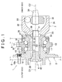
- FIG. 1 is a longitudinal sectional view that shows the wheel supporting device according to the embodiments of the invention.
- the wheel supporting device 1 is fixed to a suspension 5 of a vehicle, such as an automobile, and is used to hold a wheel 6 rotatable.
- the wheel supporting device 1 includes a hub unit 2, a joint (constant velocity joint) 3 and a bolt 4.
- the bolt 4 may function as a coupling member that couples the hub unit 2 to the joint 3.
- the hub unit 2 is fixed to the suspension 5, and the wheel 6 is fitted to the hub unit 2.
- the joint 3 is coupled to the hub unit 2, and transmits rotary torque to the hub unit 2.
- the bolt 4 may function as the coupling member that couples the hub unit 2 to the joint 3.
- the left side is the axially outer side (the outer side in the vehicle lateral direction)
- the right side is the axially inner side (the inner side in the vehicle lateral direction).
- the hub unit 2 includes a fixed ring 10, a rotary ring 11 and balls 12 that may function as rolling elements.
- the fixed ring 10 is fixed to the suspension 5 with bolts (not shown).
- the rotary ring 11 is fitted to the wheel 6.
- the balls 12 are provided between the fixed ring 10 and the rotary ring 11.
- the fixed ring 10 is provided radially outward of the rotary ring 11.
- the fixed ring 10 and the rotary ring 11 are arranged coaxially with the balls 12 interposed therebetween.
- the fixed ring 10 has a cylindrical body portion 15 and a flange 16.
- the body portion 15 has raceway surfaces 13 and 14 on its inner periphery.
- the flange 16 extends radially outward from the body portion 15.
- the flange 16 is fixed to the suspension 5. In this way, the hub unit 2 is fixed to the vehicle body side member.
- the rotary ring 11 has a hollow shaft portion 17, a flange 18, and an annular inner ring member 19.
- the shaft portion 17 has a through-hole 27 at its center.
- the flange 18 extends radially outward from part of an axially outer side portion of the shaft portion 17.
- the inner ring member 19 is fitted to the outer periphery of an axially inner side portion of the shaft portion 17.
- the through-hole 27 is linearly formed along the central axis of the rotary ring 11.
- the central axis of the rotary ring 11 coincides with the central axis C 1 of the hub unit 2.
- the wheel 6 is fixed to the flange 18 with bolts 18a.
- the inner ring member 19 is fixed to the shaft portion 17, through clinching, by a large-diameter portion 20.
- the large-diameter portion 20 is formed by plastically deforming the axially inner end portion of the shaft portion 17 radially outward.
- the outer peripheries of the shaft portion 17 and inner ring member 19 have a raceway surface 21 and a raceway surface 22, respectively.
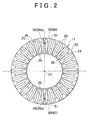
- a first spline 25 is formed on an axially inner end face 24 of the large-diameter portion 20 of the shaft portion 17.
- the axially inner end face 24 of the large-diameter portion 20 is formed of an annular face that faces inward in the vehicle lateral direction.
- the first spline 25 is formed on the annular face.
- the first spline 25 has a plurality of projections 26 that are aligned in the circumferential direction.
- the projections 26 are arranged so as to radiate from the central axis C1 side of the hub unit 2. That is, the longitudinal direction of each projection 26 extends in the radial direction. Grooves 29, which extend radially, are formed between the projections 26 adjacent to each other in the circumferential direction.
- the projections 26 have the same shape, and the grooves 29 have the same shape.
- the first spline 25 is configured such that projections and recesses are alternately formed in the circumferential direction by the projections 26 and the grooves 29.
- the balls 12 are arranged in the circumferential direction, and the balls 12 are arranged in two rows.
- the balls 12 in one of the rows roll between the raceway surfaces 13 and 21, and the balls 12 in the other one of the rows roll between the raceway surfaces 14 and 22.
- a double row angular contact ball bearing is formed of the balls 12, the fixed ring 10, and the rotary ring 11.
- the balls 12 in each row are retained at equal intervals in the circumferential direction by a cage 23.
- the joint 3 includes an inner ring 31, an outer ring 32 and a plurality of balls 33.
- the inner ring 31 is fixed to an axially outer end portion of a drive shaft 30.
- the outer ring 32 is provided radially outward of the inner ring 31.
- the balls 33 are provided between the inner ring 31 and the outer ring 32.
- the outer ring 32 has a closed-end cylindrical shape.
- the outer ring 32 has a cylindrical portion 34 having a cylindrical shape, and a bottom portion 35 that is integrated with an axially outer portion of the cylindrical portion 34.
- a bolt hole 36 is formed at the center of the bottom portion 35.
- a distal end portion 41 of the bolt 4 is screwed into the bolt hole 36.
- a second spline 38 is formed on an axially outer end face 37 of the bottom portion 35 of the joint 3.
- the axially outer end face 37 of the bottom portion 35 is formed of an annular face that faces outward in the vehicle lateral direction.
- the second spline 38 is formed on the annular face.
- the second spline 38 has a plurality of projections 39 that are aligned in the circumferential direction.
- the projections 39 are arranged so as to radiate from the central axis C2 side of the joint 3. That is, the longitudinal direction of each projection 39 extends in the radial direction.
- Groove 40 which extend radially, are formed between the projections 39 adjacent to each other in the circumferential direction.
- the projections 39 have the same shape, and the grooves 40 have the same shape.
- the second spline 38 is configured such that projections and recesses are alternately formed in the circumferential direction by the projections 39 and the grooves 40.
- the second spline 38 is in mesh with the first spline 25 (see FIG. 1 and FIG. 2 ). Through the mesh between the first spline 25 and the second spline 38, torque is transmitted between the rotary ring 11 of the hub unit 2 and the outer ring 32 of the joint 3.
- the bolt 4 is a member that fastens the rotary ring 11 and the outer ring 32, which is arranged axially inward of and coaxially with the rotary ring 11, to each other in the axial direction to couple the rotary ring 11 to the outer ring 32.
- the bolt 4 has a bolt head 42 and the distal end portion 41.
- the bolt head 42 is larger in diameter than the through-hole 27 of the rotary ring 11.
- the distal end portion 41 is screwed into the bolt hole 36 formed in the bottom portion 35 of the outer ring 32.
- the distal end portion 41 of the bolt 4 is inserted, from the axially outer side, into the through-hole 27, and then screwed into the bolt hole 36 of the outer ring 32.
- the bolt 4 couples the rotary ring 11 to the outer ring 32 by fastening the rotary ring 11 and the outer ring 32 together in the axial direction.
- the bolt head 42 is larger in diameter than the through-hole 27, the bolt head 42 axially contacts an axially outer end face 28 of the shaft portion 17 to prevent the bolt 4 from slipping out of the rotary ring 11 toward the axially inner side.
- the hub unit 2 is coupled to the joint 3, and torque is transmitted from the joint 3 to the hub unit 2.
- the above-described configuration is the basic configuration of the wheel supporting device 1 according to the embodiments of the invention.
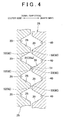
- FIG. 4 is a sectional view that illustrates the tooth profiles (the shapes of the projections) of the first spline 25 and second spline 38.
- the projections 26 in the first spline 25, the projections 26 have the same shape and the grooves 29 have the same shape, as described above. Further, the projections 26 have the same sectional shape, and the grooves 29 have the same sectional shape. Protrusions 51 are formed on crests 50 of some of the projections 26 of the first spline 25. Note that, in FIG. 2 and FIG.
- projections 26 having the protrusions 51 are indicated by reference sign 26a in parentheses.
- the shape of the crest 50 of each projection 26a is different from the shape of the crest 50 of each of the other projections 26.
- the projections 39 have the same shape
- the grooves 40 have the same shape.
- the projections 39 have the same sectional shape
- the grooves 40 have the same sectional shape.
- the protrusion 51 is a portion that protrudes axially inward from the crest 50 (top land 60) of the projection 26, and is formed in a dot shape in the present embodiment (see FIG. 2 ). In this way, the projections 26a that are some of the projections 26 of the first spline 25 project further axially inward than the remaining projections 26 of the first spline 25 by an amount corresponding to the height of the protrusion 51.
- the protrusion 51 needs to be formed on the crest 50 of each of one or two projections 26a among the projections 26 of the first spline 25.
- the protrusion 51 is formed on the crest 50 of each of the two projections 26a, and the two projections 26a project further axially inward than the remaining projections 26.
- the projections 26a on which the protrusions 51 are formed are located at positions offset from each other by 180° about the central axis C1.
- the protrusion 51 will be described below.
- a worker brings the rotary ring 11 of the hub unit 2 and the outer ring 32 of the joint 3 closed to each other in the axial direction in order to couple the hub unit 2 to the joint 3 using the bolt 4.
- the rotary ring 11 and the outer ring 32 are brought into contact with each other in the axial direction, and then the hub unit 2 and the joint 3 are fastened together with the bolt 4 in the axial direction.
- the rotary ring 11 and the outer ring 32 are assembled together.
- alignment between the first spline 25 and the second spline 38 in the circumferential direction is not particularly performed. Therefore, as shown in FIG. 4 , the crests 50 (top lands 60) of the projections 26 of the first spline 25 may contact crests 52 (top lands 62) of the projections 39 of the second spline 38 in the axial direction.
- the protrusions 51 reliably place the mesh between the rotary ring 11 and the outer ring 32 in an unstable state to cause a play therebetween.
- the number of the projections 26a on which the protrusions 51 are formed may be other than two, for example, one. In this case as well, the mesh between the rotary ring 11 and the outer ring 32 is reliably placed in an unstable state to cause a play therebetween.
- the number of the projections 26a on which the protrusions 51 are formed may be other than one and two, for example, may be three, or four or more.
- the projections 26a on which the protrusions 51 are formed need to be located at positions at unequal intervals in the circumferential direction (positions at unequal intervals).
- the protrusions 51 are formed on the crests 50 of the projections 26a of the first spline 25 of the hub unit 2.
- the protrusions 51 may be formed on the crests 52 of the projections 39 of the second spline 38 of the joint 3. That is, the protrusions 51 need to be formed on the crests of the projections of one of the first spline 25 and the second spline 38.
- the axially inner end portion of the shaft portion 17 is plastically deformed radially outward to form the large-diameter portion 20.
- the first spline 25 and the protrusions 51 are formed. That is, although not shown in the drawing, during formation of the large-diameter portion 20 or after formation of the large-diameter portion 20, a punch is pressed against the axially inner end portion of the shaft portion 17 in the axial direction by pressing work to form the first spline 25.
- the distal end face of the punch has a corrugated surface for forming the first spline 25.
- Recesses (holes) are formed on part of the corrugated surface of the punch, and the material that forms the axially inner end portion of the shaft portion 17 partially flows into the recesses and becomes the protrusions 51. With the above-described forming method, the protrusions 51 are easily formed.
- each protrusion 51 may be in a shape other than a dot shape. Although not shown in the drawing, each protrusion 51 may be long in the longitudinal direction of the projection 26a. For example, a band-shaped protrusion may be formed along the overall length of the projection 26a. Further, instead of forming the protrusions 51, there may be employed a configuration in which some of the projections 26 themselves project in the axial direction by a larger amount than the remaining projections 26, that is, the height of the some of the projections 26 is larger than that of the remaining projections 26.
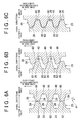
- FIG. 6A to FIG. 6C are sectional views that illustrate the tooth profiles (the shapes of the projections) of the first spline 25 and second spline 38.
- the projections 26 have the same shape and the grooves 29 have the same shape in the first spline 25. Further, the projections 26 have the same sectional shape and the grooves 29 have the same sectional shape.
- the projections 39 have the same shape and the grooves 40 have the same shape in the second spline 38. Further, the projections 39 have the same sectional shape and the grooves 40 have the same sectional shape.
- the top land 60 of each of the projections 26 of the first spline 25 is inclined with respect to an imaginary plane H (see FIG. 6A ) that is perpendicular to the central axis C1 of the rotary ring 11 and the central axis C2 of the outer ring 32.
- the inclination direction of each top land 60 is the same along the circumferential direction.
- the top land 62 of each of the projections 39 of the second spline 38 is also inclined with respect to the plane H.
- the inclination direction of each top land 62 is the same along the circumferential direction.
- the top lands 60 are inclined with respect to the plane H such that the height thereof is reduced toward one side in the circumferential direction
- the top lands 62 are inclined with respect to the plane H such that the height thereof is increased toward the one side in the circumferential direction.
- the outer ring 32 and the rotary ring 11 are placed in the fixed state. After that, the fixed state is continued.
- the bolt 4 is rotated toward one side in the circumferential direction with respect to the outer ring 32 and the rotary ring 11 that are in the fixed state. Due to the rotation of the bolt 4, the outer ring 32 also attempts to rotate together with the bolt 4 toward the one side in the circumferential direction.
- the direction in which the bolt 4 is rotated with respect to the outer ring 32 in order to fasten the rotary ring 11 and the outer ring 32 together in the axial direction by the bolt 4 is set as the "one side in the circumferential direction".
- top lands 60 and top lands 62 The function provided by the inclined shapes of the top lands 60 and top lands 62 will be described.
- a worker brings the rotary ring 11 of the hub unit 2 and the outer ring 32 of the joint 3 close to each other in the axial direction in order to couple to the hub unit 2 to the joint 3 using the bolt 4. Then, the rotary ring 11 and the outer ring 32 are brought into contact with each other in the axial direction, and then the hub unit 2 and the joint 3 are fastened together by the bolt 4 in the axial direction. In this way, the rotary ring 11 and the outer ring 32 are assembled together.
- the top lands 60 of the projections 26 of the first spline 25 and the top lands 62 of the projections 39 of the second spline 38 may contact each other in the axial direction.
- the inclination angle ⁇ of each of the top lands 60 and 62 with respect to the plane H is desirably larger than or equal to 8°.
- the inclination angle ⁇ is set on the basis of a coefficient of friction between the top lands 60 of the projections 26 and the top lands 62 of the projections 39.
- contact between the top lands 60 and 62 is contact between metal surfaces.
- ⁇ ⁇ 8° when the top lands 60 of the projections 26 and the top lands 62 of the projections 39 contact with each other in the axial direction through fastening of the bolt 4, axial force acts on the top lands 60 and 62.
- circumferential component of force is caused by the inclined faces (top lands 60 and 62) to cause a slip in the circumferential direction between the top lands 60 and 62.
- both the top lands 60 of the projections 26 of the first spline 25 and the top lands 62 of the projections 39 of the second spline 38 are inclined.
- only one of the first spline 25 and the second spline 38 may have projections with inclined top lands.
- FIG. 7 is a longitudinal sectional view of the wheel supporting device 1 according to the background of the present invention.
- the basic configuration is the same as the configuration illustrated in FIG. 1 , so the description thereof is omitted here.
- the bolt 4 has the bolt head 42 and the distal end portion 41.
- the bolt head 42 is larger in diameter than the through-hole 27 of the rotary ring 11 of the hub unit 2.
- the distal end portion 41 is screwed into the bolt hole 36 formed in the bottom portion 35 of the outer ring 32 of the joint 3.
- the distal end portion 41 of the bolt 4 is inserted, from the axially outer side, into the rotary ring 11 to screw the distal end portion 41 into the bolt hole 36.
- the rotary ring 11 and the outer ring 32 are fastened together in the axial direction to couple the rotary ring 11 to the outer ring 32.
- the rotary ring 11 has a first guide portion 71 and a second guide portion 72 that is located axially inward of the first guide portion 71.
- the first guide portion 71 and the second guide portion 72 guide the bolt 4 with respect to the radial direction.
- the first guide portion 71 is formed of a circular hole formed at an axially outer end portion of the rotary ring 11.
- the first guide portion 71 is defined by a cylindrical portion 73 that projects axially outward from the axially outer end portion of the rotary ring 11.
- the inner periphery of the cylindrical portion 73 has a diameter slightly larger than the diameter of the outer periphery of the bolt head 42 that has a circular shape as viewed from the axial direction.
- the cylindrical portion 73 (inner periphery) and the through-hole 27 are formed coaxially with the rotary ring 11.
- the bolt head 42 is guided with respect to the radial direction by the inner periphery of the cylindrical portion 73, and the bolt 4 is guided so as to be coaxial with the rotary ring 11.
- the cylindrical portion 73 is a wheel spigot that is passed through a hole 6a formed at the center of the wheel 6 to be fitted to the flange 18. That is, the cylindrical portion 73 not only functions as an assist member for fitting the wheel 6 to the flange 18 but also functions to as a guide that guides the bolt 4.
- the second guide portion 72 is formed of an annular member that is fitted in an axially inner-side portion of the through-hole 27 of the rotary ring 11. That is, the second guide portion 72 is a member separate from the rotary ring 11 (shaft portion 17). The second guide portion 72 is press-fitted into the through-hole 27 to be fixed. In addition, the second guide portion 72 is desirably made of resin in order to reduce the weight of the hub unit 2.
- the diameter of the inner periphery of the second guide portion 72 is slightly larger than the outside diameter of the shaft portion 43 at a portion under the bolt head.
- the second guide portion 72 guides part of the shaft portion 43 in the radial direction, at the axially inner side of the rotary ring 11, and guides the bolt 4 such that the bolt 4 is coaxial with the rotary ring 11.
- the clearance between the first guide portion 71 (the inner periphery of the cylindrical portion 73) and the outer periphery of the circular bolt head 42 is desirably smaller than or equal to 0.5 mm in diameter.
- the clearance between the inner periphery of the second guide portion 72 and the outer periphery of the shaft portion 43 is desirably smaller than or equal to 0.3 mm in diameter.
- the bolt hole 36 is formed about the central axis C2 of the joint 3 (outer ring 32). Therefore, by screwing the distal end portion 41 of the bolt 4 into the bolt hole 36, the bolt 4 and the outer ring 32 of the joint 3 are coupled to each other so as to be coaxial with each other.
- the distal end portion 41 of the bolt 4 is inserted from the axially outer side into the through-hole 27 of the rotary ring 11, and the bolt 4 is guided by the first guide portion 71 and the second guide portion 72. In this way, the bolt 4 and the rotary ring 11 are coaxially arranged.
- the bolt 4 is screwed into the bolt hole 36 of the outer ring 32. In this way, the bolt 4 and the outer ring 32 are coaxially arranged. As a result, the rotary ring 11 and the outer ring 32 are coaxially arranged.
- the top lands of the projections 26 of the first spline 25 of the hub unit 2 and the top lands of the projections 39 of the second spline 38 of the joint 3 tend to contact each other in the axial direction.
- the rotary ring 11 and the outer ring 32 are coaxially arranged, it is possible to prevent the assembly from being completed with the top lands of the projections 26 of the first spline 25 and the top lands of the projections 39 of the second spine 38 remain in contact with each other due to misalignment between the rotary ring 11 and the outer ring 32.
- the second guide portion 72 is formed of an annular member that is fitted in the through-hole 27. Therefore, the diameter of the through-hole 27 need not be reduced, and it is possible to increase the diameter of the through-hole 27. That is, the thickness of the rotary ring 11 is reduced, and the weight of the hub unit 2 is reduced.
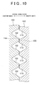
- FIG. 8 is a view that illustrates the first spline 25 and the second spline 38 according to the present embodiment.
- the first spline 25 is formed on the axially inner end face 24 of the rotary ring 11.
- the first spline 25 is referred to as "first main spline 25”.
- the second spline 38 is formed on the axially outer end face 37 of the outer ring 32.
- the second spline 38 is referred to as "second main spline 38".
- the axially inner end face 24 of the rotary ring 11 (large-diameter portion 20) is formed of an annular face that faces inward in the axial direction.
- the first main spline 25 is formed on this annular face.
- the inner periphery of the axially inner end portion (large-diameter portion 20) of the rotary ring 11 is formed of an arc face 80 that gradually reduces in diameter from the radially inner side portion of the axially inner end face 24.
- the arc face 80 is contiguous with the inner periphery of the rotary ring 11, which extends linearly in the axial direction.
- a first sub-spline 81 is formed on the arc face 80.
- the first sub-spline 81 has a plurality of projections 82 aligned in the circumferential direction.
- the projections 82 are arranged so as to radiate along the arc face 80.
- the projections 82 are formed to extend along the direction in which the diameter of the arc face 80 increases.
- Grooves 83 which extend in the radial direction along the arc face 80, are formed between projections 82 adjacent to each other in the circumferential direction.
- the projections 82 have the same shape, and the grooves 83 have the same shape.
- the projections 82 of the first sub-spline 81 are formed to extend axially outward so as to be contiguous with and in the same phase as the projections 26 of the first main spline 25.
- the axially outer end face 37 of the outer ring 32 is formed of an annular face that faces outward in the axial direction.
- the second main spline 38 is formed on this annular face.
- the bottom portion 35 of the outer ring 32 has a circular cylindrical portion 90 that projects outward in the axial direction.
- the outer periphery of the cylindrical portion 90 has an arc face 91 that gradually reduces in diameter from the radially inner side portion of the axially outer end face 37.
- the arc face 91 is contiguous with the outer periphery of a portion of the cylindrical portion 90, which extends linearly in the axial direction.
- a second sub-spline 92 is formed on the arc face 91.
- the second sub-spline 92 has a plurality of projections 93 aligned in the circumferential direction.
- the projections 93 are arranged so as to radiate along the arc face 91.
- the projections 93 are formed to extend in the direction in which the diameter of the arc face 91 increases.
- Grooves 84 which extend in the radial direction along the arc face 91, are formed between projections 93 adjacent to each other in the circumferential direction.
- the projections 93 have the same shape, and the grooves 94 have the same shape.
- the projections 93 of the second sub-spline 92 are formed to extend axially outward so as to be contiguous with and in the same phase as the projections 39 of the second main spline 38.
- the first sub-spline 81 of the hub unit 2 is in mesh with the second sub-spline 92 of the joint 3. Note that, in the state where the first sub-spline 81 is completely in mesh with the second sub-spline 92 (state shown in FIG. 9 ), the first main spline 25 is in mesh with the second main spline 38.
- the area in which the splines are in mesh with each other to transmit torque between the hub unit 2 and the joint 3 is made larger than that in the case shown in FIG. 1 .
- the first sub-spline 81 and second sub-spline 92 function as guide members for causing the first main spline 25 of the hub unit 2 to mesh with the second main spline 38 of the joint 3. That is, a worker brings the rotary ring 11 of the hub unit 2 and the outer ring 32 of the joint 3 close to each other in the axial direction in order to couple to the hub unit 2 to the joint 3 using the bolt 4.
- the first sub-spline 81 of the rotary ring 11 is meshed with the second sub-spline 92 of the outer ring 32.
- the first main spline 25 and the second main spline 38 are completely meshed with each other. That is, the first and second sub-splines 81 and 92 function as axial guides for meshing the first and second main splines 25 and 38 with each other.
- the projections 82 and 93 may have shapes other than the above-described ones, for example, the projections 82 and 93 may extend linearly instead of extending in an arc-shape.
- the projections 82 and 93 may be in any shapes as long as the first sub-spline 81 and the second sub-spline 92 are able to guide the first main spline 25 and the second main spline 38 in the axial direction to facilitate meshing between the first main spline 25 and the second main spline 38.
- the wheel supporting device according to the invention is not limited to the illustrated embodiments, and various modifications may be made within the scope of the invention.
- the type of the joint 3 may be other than the above-described one.
Landscapes
- Engineering & Computer Science (AREA)
- Mechanical Engineering (AREA)
- General Engineering & Computer Science (AREA)
- Rolling Contact Bearings (AREA)
Claims (6)
- Radlagervorrichtung (1), mit:einer Nabeneinheit (2), die einen fixen Ring (10), der an einer Fahrzeugkarosserie (5) befestigt ist, einen Rotationsring (11), an welchem ein Rad (6) befestigt ist und welcher eine erste Keilverzahnung (25) an einer axialen Innenstirnfläche (24) aufweist, und zwischen dem fixen Ring (10) und dem Rotationsring (11) vorgesehene Wälzelemente (12) aufweist;einem Gelenk (3), das einen Außenring (32) aufweist, der eine zweite Keilverzahnung (38) aufweist, welche mit der ersten Keilverzahnung (25) an einer axialen Außenstirnfläche so in Eingriff ist, dass ein Drehmoment zwischen dem Außenring (32) und dem Rotationsring (11) übertragen wird; undeinem axial innerhalb des Rotationsrings (11) angeordneten Koppelelement (4), welches den Rotationsring (11) und den Außenring (32) in einer Axialrichtung miteinander befestigt, um den Rotationsring (11) und den Außenring (32) miteinander zu koppeln,dadurch gekennzeichnet, dasszumindest ein Vorsprung (26a) aus einer Vielzahl von Vorsprüngen (26, 39) von der ersten Keilverzahnung (25) oder der zweiten Keilverzahnung (38) in der Axialrichtung um einen größeren Betrag als die verbleibenden Vorsprünge (26, 39) der ersten Keilverzahnung (25) oder der zweiten Keilverzahnung (38) vorspringt.
- Radlagervorrichtung (1) nach Anspruch 1, wobei ein Vorsprung (51) an einer Krone (50, 52) des zumindest einen Vorsprungs (26a) ausgebildet ist.
- Radlagervorrichtung (1) nach Anspruch 1 oder 2, wobei der zumindest eine Vorsprung (26a) ein Vorsprung (26a) ist oder zwei Vorsprünge (26a, 26a) sind, die von den Vorsprüngen der ersten Keilverzahnung (25) oder der zweiten Keilverzahnung (38) umfasst werden.
- Radlagervorrichtung (1), mit:einer Nabeneinheit (2), die einen fixen Ring (10), der an einer Fahrzeugkarosserie (5) befestigt ist, einen Rotationsring (11), an welchem ein Rad (6) befestigt ist und welcher eine erste Keilverzahnung (25) an einer axialen Innenstirnfläche (24) aufweist, und zwischen dem fixen Ring (10) und dem Rotationsring (11) vorgesehene Wälzelemente (12) aufweist;einem Gelenk (3), das einen Außenring (32) aufweist, der eine zweite Keilverzahnung (38) aufweist, welcher mit der ersten Keilverzahnung (25) an einer axialen Außenstirnfläche so in Eingriff ist, dass ein Drehmoment zwischen dem Außenring (32) und dem Rotationsring (11) übertragen wird; undeinem axial innerhalb des Rotationsrings (11) angeordneten Koppelelement (4), welches den Rotationsring (11) und den Außenring (32) in einer Axialrichtung miteinander befestigt, um den Rotationsring (11) und den Außenring (32) miteinander zu koppeln, wobeidie erste Keilverzahnung (25) und die zweite Keilverzahnung (38) jeweils eine Vielzahl von Vorsprüngen (26, 39) aufweisen, die in einer Umfangsrichtung ausgerichtet sind,dadurch gekennzeichnet, dassSpitzenflächen (60, 62) der Vorsprünge (26, 39) der ersten Keilverzahnung (25) und/oder der zweiten Keilverzahnung (38) bezüglich einer Ebene (H), welche senkrecht zu einer Mittelachse des Rotationsrings (11) und einer Mittelachse des Außenrings (32) ist, geneigt sind.
- Radlagervorrichtung (1) nach Anspruch 4, wobei:die Spitzenflächen (60, 62) der Vorsprünge (26, 39) der ersten Keilverzahnung (25) und der zweiten Keilverzahnung (38) bezüglich der Ebene (H) geneigt sind; undeine Höhe der Spitzenflächen (60, 62) der Vorsprünge (26, 39) der ersten Keilverzahnung (25) oder der zweiten Keilverzahnung (38) in Richtung einer Seite in der Umfangsrichtung reduziert ist und eine Höhe der Spitzenflächen (60, 62) der Vorsprünge (26, 39) der anderen Keilverzahnung der ersten Keilverzahnung (25) und der zweiten Keilverzahnung (38) in Richtung der einen Seite in der Umfangsrichtung erhöht ist.
- Radlagervorrichtung (1), mit:einer Nabeneinheit (2), die einen fixen Ring (10), der an einer Fahrzeugkarosserie (5) befestigt ist, einen Rotationsring (11), an welchem ein Rad (6) befestigt ist und welcher eine erste Hauptkeilverzahnung (25) aufweist, die eine Vielzahl von Vorsprüngen (26) an einer axialen Innenendfläche (24) ausweist, und zwischen dem fixen Ring (10) und dem Rotationsring (11) vorgesehene Wälzkörper (12) aufweist;einem Gelenk (3), das einen Außenring (32) einer zweiten Hauptkeilverzahnung (38) aufweist, welche mit der ersten Hauptkeilverzahnung (25) in Eingriff ist und eine Vielzahl von Vorsprüngen (39) an einer axialen Außenendfläche aufweist, derart, dass ein Drehmoment zwischen dem Außenring (32) und dem Rotationsring (11) übertragen wird; undeinem axial innerhalb des Rotationsrings (11) angeordneten Koppelelement (4), das den Rotationsring (11) und den Außenring (32) in einer Axialrichtung miteinander befestigt, um den Rotationsring (11) und den Außenring (32) miteinander zu koppeln, wobeider Rotationsring (11) eine erste Nebenkeilverzahnung (81) aufweist, die eine Vielzahl von sich in Axialrichtung erstreckenden Vorsprüngen (82) aufweist, um mit den Vorsprüngen (39) der zweiten Hauptkeilverzahnung (38) angrenzend und in derselben Phase mit diesen zu sein, wobei die zweite Nebenkeilverzahnung (92) mit der ersten Nebenkeilverzahnung (81) in Eingriff ist,dadurch gekennzeichnet, dassdie erste Nebenkeilverzahnung (81) und die zweite Nebenkeilverzahnung (92) die erste Hauptkeilverzahnung (25) und die zweite Hauptkeilverzahnung (38) in der Axialrichtung führen, um ein Ineinandergreifen zwischen der ersten Hauptkeilverzahnung (25) und der zweiten Hauptkeilverzahnung (38) zu erleichtern.
Applications Claiming Priority (1)
| Application Number | Priority Date | Filing Date | Title |
|---|---|---|---|
| JP2011186125A JP5974437B2 (ja) | 2011-08-29 | 2011-08-29 | 車輪支持装置 |
Publications (3)
| Publication Number | Publication Date |
|---|---|
| EP2565051A2 EP2565051A2 (de) | 2013-03-06 |
| EP2565051A3 EP2565051A3 (de) | 2013-10-30 |
| EP2565051B1 true EP2565051B1 (de) | 2015-01-07 |
Family
ID=46603780
Family Applications (1)
| Application Number | Title | Priority Date | Filing Date |
|---|---|---|---|
| EP12179329.3A Not-in-force EP2565051B1 (de) | 2011-08-29 | 2012-08-06 | Radlagervorrichtung |
Country Status (4)
| Country | Link |
|---|---|
| US (1) | US9005043B2 (de) |
| EP (1) | EP2565051B1 (de) |
| JP (1) | JP5974437B2 (de) |
| CN (1) | CN102963213B (de) |
Families Citing this family (8)
| Publication number | Priority date | Publication date | Assignee | Title |
|---|---|---|---|---|
| DE102012214884B3 (de) * | 2012-08-22 | 2014-02-27 | Hirschvogel Umformtechnik Gmbh | Kupplungsanordnung und Kupplungselement |
| JP2014058232A (ja) * | 2012-09-18 | 2014-04-03 | Jtekt Corp | 車両用軸受装置 |
| DE102014203206A1 (de) * | 2014-02-24 | 2015-08-27 | Schaeffler Technologies AG & Co. KG | Genietete Radlagereinheit mit verbesserter Klemmkraft |
| US10247245B2 (en) * | 2015-11-10 | 2019-04-02 | Ford Global Technologies, Llc | Bevel facespline with line contact |
| JP6964391B2 (ja) * | 2016-03-10 | 2021-11-10 | Ntn株式会社 | 車輪用軸受装置とその製造方法 |
| US11098764B2 (en) * | 2017-05-22 | 2021-08-24 | Steering Solutions Ip Holding Corporation | Universal joint or constant velocity joint torque transmission interface |
| DE102017212060A1 (de) * | 2017-07-14 | 2019-01-17 | Bayerische Motoren Werke Aktiengesellschaft | Kopplungseinrichtung |
| DE102021126242A1 (de) | 2021-10-11 | 2023-04-13 | Schaeffler Technologies AG & Co. KG | Stirnverzahnung mit Prägeradien |
Family Cites Families (11)
| Publication number | Priority date | Publication date | Assignee | Title |
|---|---|---|---|---|
| EP0048101B1 (de) * | 1980-09-13 | 1985-02-20 | GKN Transmissions Limited | Lager- und Kreuzgelenkeinheit |
| JP2005170208A (ja) | 2003-12-10 | 2005-06-30 | Honda Motor Co Ltd | 駆動輪用軸受装置及び前記駆動輪用軸受装置と等速ジョイントとの取り外し構造 |
| DE102005016427A1 (de) | 2005-04-08 | 2006-10-12 | Schaeffler Kg | Bund mit stirnseitigen Zähnen für eine antreibbare Radnabe |
| EP2103451B1 (de) * | 2006-12-28 | 2016-03-09 | JTEKT Corporation | Radstützvorrichtung |
| US8210752B2 (en) | 2007-09-26 | 2012-07-03 | Jtekt Corporation | Wheel supporting device |
| JP2009078675A (ja) | 2007-09-26 | 2009-04-16 | Jtekt Corp | 車輪支持装置 |
| EP2441594B1 (de) | 2007-10-03 | 2013-04-24 | JTEKT Corporation | Radstützvorrichtung |
| JP5167903B2 (ja) * | 2008-03-28 | 2013-03-21 | 株式会社ジェイテクト | 車輪用軸受装置 |
| DE112009001354B4 (de) * | 2008-06-04 | 2019-05-23 | Ntn Corp. | Antriebsrad-Lagervorrichtung |
| DE102008050127A1 (de) | 2008-10-06 | 2010-04-08 | Schaeffler Kg | Vorrichtung zur axialen Fixierung |
| US20110123264A1 (en) * | 2009-11-25 | 2011-05-26 | Gm Global Technology Operations, Inc. | Conical Face Spline for Half-Shafts, Hub Bearings and the Like |
-
2011
- 2011-08-29 JP JP2011186125A patent/JP5974437B2/ja not_active Expired - Fee Related
-
2012
- 2012-07-31 US US13/562,771 patent/US9005043B2/en not_active Expired - Fee Related
- 2012-08-06 EP EP12179329.3A patent/EP2565051B1/de not_active Not-in-force
- 2012-08-28 CN CN201210311336.0A patent/CN102963213B/zh not_active Expired - Fee Related
Also Published As
| Publication number | Publication date |
|---|---|
| EP2565051A2 (de) | 2013-03-06 |
| CN102963213A (zh) | 2013-03-13 |
| JP5974437B2 (ja) | 2016-08-23 |
| US20130053155A1 (en) | 2013-02-28 |
| EP2565051A3 (de) | 2013-10-30 |
| JP2013047056A (ja) | 2013-03-07 |
| US9005043B2 (en) | 2015-04-14 |
| CN102963213B (zh) | 2016-03-16 |
Similar Documents
| Publication | Publication Date | Title |
|---|---|---|
| EP2565051B1 (de) | Radlagervorrichtung | |
| US8801294B2 (en) | Bearing device for a wheel | |
| KR20070072548A (ko) | 허브 유닛과 구름 베어링장치 및 그 제조방법 및 구름베어링장치의 조립장치 및 그 조립방법 | |
| EP2105321B1 (de) | Radlagereinheit und zugehöriges Herstellungsverfahren | |
| JP2013047056A5 (de) | ||
| JP5167903B2 (ja) | 車輪用軸受装置 | |
| EP2634012B1 (de) | Radstützvorrichtung | |
| US8714573B2 (en) | Vehicle bearing apparatus | |
| JP2010047059A (ja) | 車輪用軸受装置およびアクスルモジュール | |
| JP2009083813A (ja) | 車輪支持装置 | |
| KR101454905B1 (ko) | 휠 베어링 및 이를 사용한 휠 베어링 조립체 | |
| JP2007333154A (ja) | 等速自在継手 | |
| KR101867686B1 (ko) | 하우징 일체형 액슬 | |
| EP2623334B1 (de) | Radstützvorrichtung | |
| KR20160103564A (ko) | 휠 베어링 | |
| JP5826781B2 (ja) | 車輪用軸受装置の製造方法 | |
| JP2009234542A (ja) | 車輪用軸受装置 | |
| EP2634013B1 (de) | Radstützvorrichtung | |
| JP4904980B2 (ja) | 車軸用軸受装置 | |
| JP7235182B1 (ja) | ボールねじ装置およびその製造方法 | |
| JP2010023800A (ja) | 車輪用軸受装置 | |
| KR101728031B1 (ko) | 휠 베어링 및 그 제작 방법 | |
| JP5561338B2 (ja) | 車輪用軸受装置 | |
| KR20160136936A (ko) | 휠 베어링 및 그 제작 방법 | |
| JP5471496B2 (ja) | 車輪駆動用軸受ユニット |
Legal Events
| Date | Code | Title | Description |
|---|---|---|---|
| PUAI | Public reference made under article 153(3) epc to a published international application that has entered the european phase |
Free format text: ORIGINAL CODE: 0009012 |
|
| AK | Designated contracting states |
Kind code of ref document: A2 Designated state(s): AL AT BE BG CH CY CZ DE DK EE ES FI FR GB GR HR HU IE IS IT LI LT LU LV MC MK MT NL NO PL PT RO RS SE SI SK SM TR |
|
| AX | Request for extension of the european patent |
Extension state: BA ME |
|
| PUAL | Search report despatched |
Free format text: ORIGINAL CODE: 0009013 |
|
| AK | Designated contracting states |
Kind code of ref document: A3 Designated state(s): AL AT BE BG CH CY CZ DE DK EE ES FI FR GB GR HR HU IE IS IT LI LT LU LV MC MK MT NL NO PL PT RO RS SE SI SK SM TR |
|
| AX | Request for extension of the european patent |
Extension state: BA ME |
|
| RIC1 | Information provided on ipc code assigned before grant |
Ipc: B60B 27/00 20060101AFI20130925BHEP |
|
| 17P | Request for examination filed |
Effective date: 20140430 |
|
| RBV | Designated contracting states (corrected) |
Designated state(s): AL AT BE BG CH CY CZ DE DK EE ES FI FR GB GR HR HU IE IS IT LI LT LU LV MC MK MT NL NO PL PT RO RS SE SI SK SM TR |
|
| GRAP | Despatch of communication of intention to grant a patent |
Free format text: ORIGINAL CODE: EPIDOSNIGR1 |
|
| INTG | Intention to grant announced |
Effective date: 20140718 |
|
| GRAS | Grant fee paid |
Free format text: ORIGINAL CODE: EPIDOSNIGR3 |
|
| GRAA | (expected) grant |
Free format text: ORIGINAL CODE: 0009210 |
|
| AK | Designated contracting states |
Kind code of ref document: B1 Designated state(s): AL AT BE BG CH CY CZ DE DK EE ES FI FR GB GR HR HU IE IS IT LI LT LU LV MC MK MT NL NO PL PT RO RS SE SI SK SM TR |
|
| REG | Reference to a national code |
Ref country code: GB Ref legal event code: FG4D |
|
| RIN1 | Information on inventor provided before grant (corrected) |
Inventor name: HAKATA, TOSHIHIRO Inventor name: MIZUTA, SHINICHI Inventor name: WATANABE, HAJIME |
|
| REG | Reference to a national code |
Ref country code: CH Ref legal event code: EP |
|
| REG | Reference to a national code |
Ref country code: IE Ref legal event code: FG4D |
|
| REG | Reference to a national code |
Ref country code: AT Ref legal event code: REF Ref document number: 705411 Country of ref document: AT Kind code of ref document: T Effective date: 20150215 |
|
| REG | Reference to a national code |
Ref country code: DE Ref legal event code: R096 Ref document number: 602012004731 Country of ref document: DE Effective date: 20150226 |
|
| REG | Reference to a national code |
Ref country code: NL Ref legal event code: VDEP Effective date: 20150107 |
|
| REG | Reference to a national code |
Ref country code: AT Ref legal event code: MK05 Ref document number: 705411 Country of ref document: AT Kind code of ref document: T Effective date: 20150107 |
|
| REG | Reference to a national code |
Ref country code: LT Ref legal event code: MG4D |
|
| PG25 | Lapsed in a contracting state [announced via postgrant information from national office to epo] |
Ref country code: NO Free format text: LAPSE BECAUSE OF FAILURE TO SUBMIT A TRANSLATION OF THE DESCRIPTION OR TO PAY THE FEE WITHIN THE PRESCRIBED TIME-LIMIT Effective date: 20150407 Ref country code: BG Free format text: LAPSE BECAUSE OF FAILURE TO SUBMIT A TRANSLATION OF THE DESCRIPTION OR TO PAY THE FEE WITHIN THE PRESCRIBED TIME-LIMIT Effective date: 20150407 Ref country code: FI Free format text: LAPSE BECAUSE OF FAILURE TO SUBMIT A TRANSLATION OF THE DESCRIPTION OR TO PAY THE FEE WITHIN THE PRESCRIBED TIME-LIMIT Effective date: 20150107 Ref country code: SE Free format text: LAPSE BECAUSE OF FAILURE TO SUBMIT A TRANSLATION OF THE DESCRIPTION OR TO PAY THE FEE WITHIN THE PRESCRIBED TIME-LIMIT Effective date: 20150107 Ref country code: ES Free format text: LAPSE BECAUSE OF FAILURE TO SUBMIT A TRANSLATION OF THE DESCRIPTION OR TO PAY THE FEE WITHIN THE PRESCRIBED TIME-LIMIT Effective date: 20150107 Ref country code: LT Free format text: LAPSE BECAUSE OF FAILURE TO SUBMIT A TRANSLATION OF THE DESCRIPTION OR TO PAY THE FEE WITHIN THE PRESCRIBED TIME-LIMIT Effective date: 20150107 Ref country code: HR Free format text: LAPSE BECAUSE OF FAILURE TO SUBMIT A TRANSLATION OF THE DESCRIPTION OR TO PAY THE FEE WITHIN THE PRESCRIBED TIME-LIMIT Effective date: 20150107 |
|
| PG25 | Lapsed in a contracting state [announced via postgrant information from national office to epo] |
Ref country code: IS Free format text: LAPSE BECAUSE OF FAILURE TO SUBMIT A TRANSLATION OF THE DESCRIPTION OR TO PAY THE FEE WITHIN THE PRESCRIBED TIME-LIMIT Effective date: 20150507 Ref country code: NL Free format text: LAPSE BECAUSE OF FAILURE TO SUBMIT A TRANSLATION OF THE DESCRIPTION OR TO PAY THE FEE WITHIN THE PRESCRIBED TIME-LIMIT Effective date: 20150107 Ref country code: RS Free format text: LAPSE BECAUSE OF FAILURE TO SUBMIT A TRANSLATION OF THE DESCRIPTION OR TO PAY THE FEE WITHIN THE PRESCRIBED TIME-LIMIT Effective date: 20150107 Ref country code: GR Free format text: LAPSE BECAUSE OF FAILURE TO SUBMIT A TRANSLATION OF THE DESCRIPTION OR TO PAY THE FEE WITHIN THE PRESCRIBED TIME-LIMIT Effective date: 20150408 Ref country code: AT Free format text: LAPSE BECAUSE OF FAILURE TO SUBMIT A TRANSLATION OF THE DESCRIPTION OR TO PAY THE FEE WITHIN THE PRESCRIBED TIME-LIMIT Effective date: 20150107 Ref country code: PL Free format text: LAPSE BECAUSE OF FAILURE TO SUBMIT A TRANSLATION OF THE DESCRIPTION OR TO PAY THE FEE WITHIN THE PRESCRIBED TIME-LIMIT Effective date: 20150107 Ref country code: LV Free format text: LAPSE BECAUSE OF FAILURE TO SUBMIT A TRANSLATION OF THE DESCRIPTION OR TO PAY THE FEE WITHIN THE PRESCRIBED TIME-LIMIT Effective date: 20150107 |
|
| REG | Reference to a national code |
Ref country code: DE Ref legal event code: R097 Ref document number: 602012004731 Country of ref document: DE |
|
| PG25 | Lapsed in a contracting state [announced via postgrant information from national office to epo] |
Ref country code: RO Free format text: LAPSE BECAUSE OF FAILURE TO SUBMIT A TRANSLATION OF THE DESCRIPTION OR TO PAY THE FEE WITHIN THE PRESCRIBED TIME-LIMIT Effective date: 20150107 Ref country code: SK Free format text: LAPSE BECAUSE OF FAILURE TO SUBMIT A TRANSLATION OF THE DESCRIPTION OR TO PAY THE FEE WITHIN THE PRESCRIBED TIME-LIMIT Effective date: 20150107 Ref country code: CZ Free format text: LAPSE BECAUSE OF FAILURE TO SUBMIT A TRANSLATION OF THE DESCRIPTION OR TO PAY THE FEE WITHIN THE PRESCRIBED TIME-LIMIT Effective date: 20150107 Ref country code: DK Free format text: LAPSE BECAUSE OF FAILURE TO SUBMIT A TRANSLATION OF THE DESCRIPTION OR TO PAY THE FEE WITHIN THE PRESCRIBED TIME-LIMIT Effective date: 20150107 Ref country code: EE Free format text: LAPSE BECAUSE OF FAILURE TO SUBMIT A TRANSLATION OF THE DESCRIPTION OR TO PAY THE FEE WITHIN THE PRESCRIBED TIME-LIMIT Effective date: 20150107 |
|
| PLBE | No opposition filed within time limit |
Free format text: ORIGINAL CODE: 0009261 |
|
| STAA | Information on the status of an ep patent application or granted ep patent |
Free format text: STATUS: NO OPPOSITION FILED WITHIN TIME LIMIT |
|
| 26N | No opposition filed |
Effective date: 20151008 |
|
| PG25 | Lapsed in a contracting state [announced via postgrant information from national office to epo] |
Ref country code: IT Free format text: LAPSE BECAUSE OF FAILURE TO SUBMIT A TRANSLATION OF THE DESCRIPTION OR TO PAY THE FEE WITHIN THE PRESCRIBED TIME-LIMIT Effective date: 20150107 |
|
| PG25 | Lapsed in a contracting state [announced via postgrant information from national office to epo] |
Ref country code: SI Free format text: LAPSE BECAUSE OF FAILURE TO SUBMIT A TRANSLATION OF THE DESCRIPTION OR TO PAY THE FEE WITHIN THE PRESCRIBED TIME-LIMIT Effective date: 20150107 |
|
| PG25 | Lapsed in a contracting state [announced via postgrant information from national office to epo] |
Ref country code: LU Free format text: LAPSE BECAUSE OF FAILURE TO SUBMIT A TRANSLATION OF THE DESCRIPTION OR TO PAY THE FEE WITHIN THE PRESCRIBED TIME-LIMIT Effective date: 20150806 Ref country code: MC Free format text: LAPSE BECAUSE OF FAILURE TO SUBMIT A TRANSLATION OF THE DESCRIPTION OR TO PAY THE FEE WITHIN THE PRESCRIBED TIME-LIMIT Effective date: 20150107 |
|
| REG | Reference to a national code |
Ref country code: CH Ref legal event code: PL |
|
| PG25 | Lapsed in a contracting state [announced via postgrant information from national office to epo] |
Ref country code: CH Free format text: LAPSE BECAUSE OF NON-PAYMENT OF DUE FEES Effective date: 20150831 Ref country code: LI Free format text: LAPSE BECAUSE OF NON-PAYMENT OF DUE FEES Effective date: 20150831 |
|
| PG25 | Lapsed in a contracting state [announced via postgrant information from national office to epo] |
Ref country code: BE Free format text: LAPSE BECAUSE OF FAILURE TO SUBMIT A TRANSLATION OF THE DESCRIPTION OR TO PAY THE FEE WITHIN THE PRESCRIBED TIME-LIMIT Effective date: 20150107 |
|
| REG | Reference to a national code |
Ref country code: IE Ref legal event code: MM4A |
|
| REG | Reference to a national code |
Ref country code: FR Ref legal event code: ST Effective date: 20160429 |
|
| PG25 | Lapsed in a contracting state [announced via postgrant information from national office to epo] |
Ref country code: IE Free format text: LAPSE BECAUSE OF NON-PAYMENT OF DUE FEES Effective date: 20150806 |
|
| PG25 | Lapsed in a contracting state [announced via postgrant information from national office to epo] |
Ref country code: FR Free format text: LAPSE BECAUSE OF NON-PAYMENT OF DUE FEES Effective date: 20150831 |
|
| PG25 | Lapsed in a contracting state [announced via postgrant information from national office to epo] |
Ref country code: MT Free format text: LAPSE BECAUSE OF FAILURE TO SUBMIT A TRANSLATION OF THE DESCRIPTION OR TO PAY THE FEE WITHIN THE PRESCRIBED TIME-LIMIT Effective date: 20150107 |
|
| GBPC | Gb: european patent ceased through non-payment of renewal fee |
Effective date: 20160806 |
|
| PG25 | Lapsed in a contracting state [announced via postgrant information from national office to epo] |
Ref country code: HU Free format text: LAPSE BECAUSE OF FAILURE TO SUBMIT A TRANSLATION OF THE DESCRIPTION OR TO PAY THE FEE WITHIN THE PRESCRIBED TIME-LIMIT; INVALID AB INITIO Effective date: 20120806 Ref country code: SM Free format text: LAPSE BECAUSE OF FAILURE TO SUBMIT A TRANSLATION OF THE DESCRIPTION OR TO PAY THE FEE WITHIN THE PRESCRIBED TIME-LIMIT Effective date: 20150107 |
|
| PG25 | Lapsed in a contracting state [announced via postgrant information from national office to epo] |
Ref country code: CY Free format text: LAPSE BECAUSE OF FAILURE TO SUBMIT A TRANSLATION OF THE DESCRIPTION OR TO PAY THE FEE WITHIN THE PRESCRIBED TIME-LIMIT Effective date: 20150107 |
|
| PG25 | Lapsed in a contracting state [announced via postgrant information from national office to epo] |
Ref country code: GB Free format text: LAPSE BECAUSE OF NON-PAYMENT OF DUE FEES Effective date: 20160806 |
|
| PG25 | Lapsed in a contracting state [announced via postgrant information from national office to epo] |
Ref country code: TR Free format text: LAPSE BECAUSE OF FAILURE TO SUBMIT A TRANSLATION OF THE DESCRIPTION OR TO PAY THE FEE WITHIN THE PRESCRIBED TIME-LIMIT Effective date: 20150107 |
|
| PG25 | Lapsed in a contracting state [announced via postgrant information from national office to epo] |
Ref country code: MK Free format text: LAPSE BECAUSE OF FAILURE TO SUBMIT A TRANSLATION OF THE DESCRIPTION OR TO PAY THE FEE WITHIN THE PRESCRIBED TIME-LIMIT Effective date: 20150107 Ref country code: PT Free format text: LAPSE BECAUSE OF FAILURE TO SUBMIT A TRANSLATION OF THE DESCRIPTION OR TO PAY THE FEE WITHIN THE PRESCRIBED TIME-LIMIT Effective date: 20150107 |
|
| PG25 | Lapsed in a contracting state [announced via postgrant information from national office to epo] |
Ref country code: AL Free format text: LAPSE BECAUSE OF FAILURE TO SUBMIT A TRANSLATION OF THE DESCRIPTION OR TO PAY THE FEE WITHIN THE PRESCRIBED TIME-LIMIT Effective date: 20150107 |
|
| PGFP | Annual fee paid to national office [announced via postgrant information from national office to epo] |
Ref country code: DE Payment date: 20210630 Year of fee payment: 10 |
|
| REG | Reference to a national code |
Ref country code: DE Ref legal event code: R119 Ref document number: 602012004731 Country of ref document: DE |
|
| PG25 | Lapsed in a contracting state [announced via postgrant information from national office to epo] |
Ref country code: DE Free format text: LAPSE BECAUSE OF NON-PAYMENT OF DUE FEES Effective date: 20230301 |