EP2562898B1 - Elektrisches Gleichstromsystem mit aktiver Dämpfung - Google Patents
Elektrisches Gleichstromsystem mit aktiver Dämpfung Download PDFInfo
- Publication number
- EP2562898B1 EP2562898B1 EP12181233.3A EP12181233A EP2562898B1 EP 2562898 B1 EP2562898 B1 EP 2562898B1 EP 12181233 A EP12181233 A EP 12181233A EP 2562898 B1 EP2562898 B1 EP 2562898B1
- Authority
- EP
- European Patent Office
- Prior art keywords
- coupled
- input
- current
- current ripple
- active
- Prior art date
- Legal status (The legal status is an assumption and is not a legal conclusion. Google has not performed a legal analysis and makes no representation as to the accuracy of the status listed.)
- Active
Links
Images

Classifications
-
- H—ELECTRICITY
- H02—GENERATION; CONVERSION OR DISTRIBUTION OF ELECTRIC POWER
- H02J—ELECTRIC POWER NETWORKS; CIRCUIT ARRANGEMENTS OR SYSTEMS FOR SUPPLYING OR DISTRIBUTING ELECTRIC POWER; SYSTEMS FOR STORING ELECTRIC ENERGY
- H02J1/00—Circuit arrangements for DC mains or DC distribution networks
- H02J1/02—Arrangements for reducing harmonics or ripples
-
- H—ELECTRICITY
- H02—GENERATION; CONVERSION OR DISTRIBUTION OF ELECTRIC POWER
- H02H—EMERGENCY PROTECTIVE CIRCUIT ARRANGEMENTS
- H02H9/00—Emergency protective circuit arrangements for limiting excess current or voltage without disconnection
- H02H9/001—Emergency protective circuit arrangements for limiting excess current or voltage without disconnection limiting speed of change of electric quantities, e.g. soft switching on or off
Definitions
- the subject matter disclosed herein relates to electric power generation and distribution, and more particularly to direct current (DC) electric power systems having active damping.
- a power converter's input LC filter without a damper introduces possible instability in the presence of constant power (i.e., negative impedance) loads.
- LC or RC damping networks are used to stabilize unstable loads.
- the LC damper is connected in series with the inductor of the input LC filter, while an RC damper is connected in parallel with the capacitor of the input LC filter.
- the size of damping networks is considerably larger than the input LC filter itself, and can therefore be difficult to manage.
- JP 2006 094682A relates to an electromagnetic power supply device for accelerators and shows how a detected current ripple of a power supplied to a load is reduced by using a variable impedance, i.e. a switch and a resistor combination.
- a first aspect of the invention refers to an active damping system described herein and defined in claim 1, including an active damper having a stabilization resistor, a stabilization switch coupled to the stabilization resistor, an active damper controller coupled to the stabilization switch, a current sensor coupled to the active damper controller.
- the system further includes a direct current power source coupled to the active damper, a constant power load and an input filter disposed between the constant power load and the active damper.
- a second aspect of the invention refers to a method of actively damping a current ripple in a direct current (DC) input in a DC system described herein and defined in claim 2, the method including receiving the DC input, selecting the current ripple from the DC input, comparing the current ripple to a reference current ripple and generating a stabilization pulse in response to the current ripple exceeding the reference current ripple.
- DC direct current
- Exemplary embodiments include systems and methods for active damping to achieve stable system operation without use of passive LC or RC dampers.
- the systems and methods described herein implement a stabilization resistor selectively connected in parallel to an input filter inductor. In response to current rippled on the DC bus, the resistor is switched to dampen the ripple.
- FIG. 1 illustrates an embodiment of active damping system 100.
- the system 100 includes a DC power source 105 electrically coupled to an active damper 110.
- the DC source 105 can be an AC generator whose output is rectified to a DC voltage that includes voltage ripples, or any other DC input that can include ripples.
- the system 100 further includes an input filter 115 electrically coupled to the active damper 110, and further electrically coupled to a constant power load 120.
- the input filter 115 is an LC filter having a capacitor 125 and an inductor 130 having values selected to filter out certain frequencies between the active damper 110 and the constant power load 120.
- the active damper 110 includes a stabilization switch 135 electrically coupled to the DC power source 105.
- the stabilization switch 135 is further coupled to a stabilization resistor 140, which is coupled to the input filter 115.
- the active damper 110 further includes an active damper controller 145 coupled to the stabilization resistor 140 and to a current sensor 150. If the system 100 becomes unstable when the input filter 115 is connected to the constant power load 120, the active damper 110 stabilizes the system 100 by connecting the stabilization resistor 140 in parallel with the inductor 130 of the input filter 115 for a period of time creating a "stabilization pulse".
- the active damper 110 is responsive to the magnitude of a current ripple on DC bus at selected frequency of oscillations and can be controlled by the active damper controller 145 as now described. As such, the active damper controller 145 is configured to close the stabilization switch 135 that decreases a steady state voltage ripple or a steady state current ripple through the stabilization resistor 140.
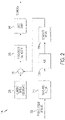
- FIG. 2 illustrates the active damper controller 145 of FIG. 1 in further detail.
- the damper controller 145 includes a current ripple input 205 from the current sensor 150 that measures the current in the system 100.
- the current ripple, from the current ripple input 205 is selected by an amplitude detector that is comprised of a band pass filter 210, an absolute function 215, and a low pass filter 220.
- the current ripple input 205 is then passed through an absolute value unit 215, and a low pass filter 220.
- the detected current ripple is compared to a current ripple reference 225 at a comparator 230.
- the current ripple reference 225 provides a known ripple factor that would be tolerant in the system 100.
- the stabilization switch 135 is enabled when the magnitude of the detected current ripple exceeds the current ripple reference 225 via a zero cross detector 235 and a gate drive 240.In one embodiment, the time to stabilize the system is short, so that the stabilization resistor 140 is subject to limited power for a short time.
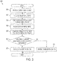
- FIG. 3 illustrates a flow chart for a method 300 of actively damping a high voltage DC system.
- the active damper controller 145 receives a current ripple input.
- the active damper controller 145 filters the current ripple input through a band pass filter at block 320, calculates the absolute value of the current ripple input at block 330 and then passes the current ripple input through a low pass filter to produce a detected current ripple at block 340.
- the detected current ripple is compared to a current ripple reference. If the detected current ripple does not exceed the current ripple reference at block 360, then the active damper controller 145 disables stabilization switch 135 at block 371 to disconnect stabilization resistor 140 to parallel inductor 115 and then exit. If the detected current ripple exceeds the current ripple reference at block 360, then at block 370 the active damper controller 145 closes the stabilization switch 135 to connect stabilization resistor 140 to parallel inductor 115 and then exits.
- the active damper controller 145 can be any suitable microcontroller or microprocessor for executing the instructions (e.g., on/off commands) described herein.
- the suitable microcontroller or microprocessor can be any custom made or commercially available processor, a central processing unit (CPU), an auxiliary processor among several processors, a semiconductor based microprocessor (in the form of a microchip or chip set), a microprocessor, or generally any device for executing software instructions.
Landscapes
- Engineering & Computer Science (AREA)
- Power Engineering (AREA)
- Dc-Dc Converters (AREA)
- Power Conversion In General (AREA)
- Networks Using Active Elements (AREA)
Claims (2)
- Aktives Dämpfungssystem (100), umfassend:eine Gleichstrom-, DC-Quelle (direct current, DC);einen aktiven Dämpfer (110), umfassend:einen Stabilisierungswiderstand (140);einen mit dem Stabilisierungswiderstand in Reihe geschalteten Stabilisierungsschalter (135);einen mit der Gleichstromquelle gekoppelten Stromsensor (150); undeine aktive Dämpfersteuerung (145), die mit dem Stromsensor und dem Stabilisierungsschalter gekoppelt ist, wobei die aktive Dämpfersteuerung umfasst:einen Bandpassfilter (210), der so konfiguriert ist, dass er Strom von dem Stromsensor (150) empfängt und eine Stromwelligkeit aus dem empfangenen Strom auswählt;eine Absolutwert-Funktionseinheit (215), die mit dem Ausgang des Bandpassfilters gekoppelt ist;einen Tiefpassfilter (220), der mit dem Ausgang der Absolutwert-Funktionseinheit gekoppelt ist, um eine erfasste Stromwelligkeit zu erzeugen; undeinen Komparator (230), der so konfiguriert ist, dass er die erfasste Stromwelligkeit mit einer Referenz-Stromwelligkeit vergleicht;einen mit dem Ausgang des Komparators gekoppelten Nulldurchgangsdetektor (235); undein Gate-Drive (240), das mit dem Ausgang des Nulldurchgangsdetektors gekoppelt und dazu konfiguriert ist, den Stabilisierungsschalter als Reaktion darauf zu schließen, dass der Nulldurchgangsdetektor erfasst, dass die Stromwelligkeit Null durchquert;wobei das aktive Dämpfungssystem (100) ferner umfasst:eine Konstantleistungslast (120); undeinen Eingangsfilter (115), der elektrisch mit der Konstantleistungslast und dem aktiven Dämpfer (110) gekoppelt ist, wobei der Eingangsfilter ein LC-Filter ist, der einen Eingangskondensator (125) enthält, der mit einem Eingangsinduktor (130) gekoppelt ist, wobei der Eingangsinduktor (130) mit dem Stromsensor (150) in Reihe geschaltet ist; undwobei das aktive Dämpfungssystem (100) so konfiguriert ist, dass, wenn das aktive Dämpfungssystem (100) instabil wird, wenn der Eingangsfilter (115) mit der Konstantleistungslast (120) verbunden ist, der aktive Dämpfer (110) konfiguriert ist das aktive Dämpfungssystem (100) zu stabilisieren, durch Verbinden des Stabilisierungswiderstands (140) parallel mit dem Eingangsinduktor (130) des Eingangsfilters (115) für eine Zeitdauer, die einen Stabilisierungsimpuls erzeugt, wobei der aktive Dämpfer (110) konfiguriert ist um auf die Stärke der Stromwelligkeit bei einer ausgewählten Oszillationsfrequenz anzusprechen, und konfiguriert ist, um durch die aktive Dämpfersteuerung (145) gesteuert zu werden.
- Verfahren zum aktiven Dämpfen einer Stromwelligkeit in einem Gleichstrom-, DC-Eingang in ein aktives Dämpfungssystem (100), das aktive Dämpfungssystem (100) umfassend:eine Gleichstromquelle; undeinem aktiven Dämpfer (110), umfassend:einen Stabilisierungswiderstand (140);einen mit dem Stabilisierungswiderstand in Reihe geschalteten Stabilisierungsschalter (135);einen mit der Gleichstromquelle gekoppelten Stromsensor (150); undeine aktive Dämpfersteuerung (145), die mit dem Stromsensor (150) und dem Stabilisierungsschalter gekoppelt ist, die aktive Dämpfersteuerung (145) umfasst:einen Bandpassfilter (210), der so konfiguriert ist, dass er Strom von dem Stromsensor empfängt und eine Stromwelligkeit aus dem empfangenen Strom auswählt;eine Absolutwert-Funktionseinheit (215), die mit dem Ausgang des Bandpassfilters gekoppelt ist;ein Tiefpassfilter (220), der mit dem Ausgang der Absolutwert-Funktionseinheit gekoppelt ist, um eine erfasste Stromwelligkeit zu erzeugen;einen Komparator (230), der so konfiguriert ist, dass er die erfasste Stromwelligkeit mit einer Referenz-Stromwelligkeit vergleicht;einen mit dem Ausgang des Komparators gekoppelten Nulldurchgangsdetektor (235); undein Gate-Drive (240) das mit dem Ausgang des Nulldurchgangsdetektors gekoppelt und konfiguriert ist, den Stabilisierungsschalter als Reaktion darauf zu schließen, dass der Nulldurchgangsdetektor erfasst, dass die Stromwelligkeit Null durchquert;wobei das aktive Dämpfungssystem (100) ferner umfasst:eine Konstantleistungslast (120); undeinen Eingangsfilter (115), der elektrisch mit der Konstantleistungslast (120) und dem aktiven Dämpfer (110) gekoppelt ist, wobei der Eingangsfilter ein LC-Filter ist, der einen Eingangskondensator (125) enthält, der mit dem Eingangsinduktor (130) gekoppelt ist, wobei der Eingangsinduktor (130) mit dem Stromsensor (150) in Reihe geschaltet ist;wobei das Verfahren Folgendes umfasst:Empfangen des Gleichstromeingangs vom Stromdetektor am Bandpassfilter (210);Auswählen der Stromwelligkeit von dem DC-Eingang als erfasste Stromwelligkeit unter Verwendung des Bandpassfilters (210), der Absolutwert-Funktionseinheit (215) und des Tiefpassfilters (220) ;Vergleichen der erfassten Stromwelligkeit mit einer Referenz-Stromwelligkeit durch den Komparator (230); undSchließen, durch Verwendung des Gate-Drives (240), wenn das aktive Dämpfungssystem (100) instabil wird, wenn das Eingangsfilter (115) mit der Konstantleistungslast (120) verbunden ist, des Stabilisierungsschalters (135) des aktiven Dämpfers ( 110), wodurch bewirkt wird, dass der Stabilisierungswiderstand (140) des aktiven Dämpfers (110) für eine Zeitdauer parallel mit dem Eingangsinduktor (130) des Eingangsfilters (115) gekoppelt wird, wodurch ein Stabilisierungsimpuls erzeugt wird und dadurch das aktive Dämpfungssystem (100) stabilisiert wird, wobei der aktive Dämpfer (110) auf die Stärke der Stromwelligkeit bei einer ausgewählten Schwingungsfrequenz anspricht und durch die aktive Dämpfersteuerung (145) gesteuert wird.
Applications Claiming Priority (1)
| Application Number | Priority Date | Filing Date | Title |
|---|---|---|---|
| US13/218,172 US8669743B2 (en) | 2011-08-25 | 2011-08-25 | Direct current electric power system with active damping |
Publications (3)
| Publication Number | Publication Date |
|---|---|
| EP2562898A2 EP2562898A2 (de) | 2013-02-27 |
| EP2562898A3 EP2562898A3 (de) | 2016-04-06 |
| EP2562898B1 true EP2562898B1 (de) | 2022-09-28 |
Family
ID=47115220
Family Applications (1)
| Application Number | Title | Priority Date | Filing Date |
|---|---|---|---|
| EP12181233.3A Active EP2562898B1 (de) | 2011-08-25 | 2012-08-21 | Elektrisches Gleichstromsystem mit aktiver Dämpfung |
Country Status (2)
| Country | Link |
|---|---|
| US (1) | US8669743B2 (de) |
| EP (1) | EP2562898B1 (de) |
Families Citing this family (8)
| Publication number | Priority date | Publication date | Assignee | Title |
|---|---|---|---|---|
| US8952570B2 (en) | 2011-08-25 | 2015-02-10 | Hamilton Sundstrand Corporation | Active damping with a switched capacitor |
| US9923469B2 (en) * | 2016-05-09 | 2018-03-20 | Rockwell Automation Technologies, Inc. | Motor drive filter damping |
| EP3457557B1 (de) | 2017-09-15 | 2021-03-17 | Hamilton Sundstrand Corporation | Aktive stabilisierung eines gleichspannungszwischenkreises in motorantriebssystemen |
| EP3696928A1 (de) * | 2019-02-15 | 2020-08-19 | Siemens Aktiengesellschaft | Energieversorgungsnetzwerk |
| DE102020120396A1 (de) * | 2020-08-03 | 2022-02-03 | Vacon Oy | Verfahren und Vorrichtung zur Dämpfung eines LCL-Filters während des Anlaufens eines elektronischen Gerätes |
| US11689101B2 (en) * | 2020-11-12 | 2023-06-27 | Psemi Corporation | Mixed-mode power converter control |
| US11594965B2 (en) | 2020-12-14 | 2023-02-28 | Psemi Corporation | Power converter counter circuit with under-regulation detector |
| CN112865521B (zh) * | 2021-04-13 | 2022-03-29 | 浙江大学 | 用于Buck变换器恒功率负载系统的有源阻尼控制方法及系统 |
Citations (1)
| Publication number | Priority date | Publication date | Assignee | Title |
|---|---|---|---|---|
| JP2006094682A (ja) * | 2004-09-27 | 2006-04-06 | Toshiba Mitsubishi-Electric Industrial System Corp | 電源装置 |
Family Cites Families (35)
| Publication number | Priority date | Publication date | Assignee | Title |
|---|---|---|---|---|
| US4119861A (en) | 1975-10-15 | 1978-10-10 | Tokyo Shibaura Electric Company, Ltd. | Starting apparatus for gas turbine-generator mounted on electric motor driven motorcar |
| US4093900A (en) | 1976-08-11 | 1978-06-06 | General Electric Company | Dynamic brake blending for an inverter propulsion system |
| US4420784A (en) | 1981-12-04 | 1983-12-13 | Eaton Corporation | Hybrid D.C. power controller |
| US4638175A (en) | 1984-07-03 | 1987-01-20 | United Technologies Corporation | Electric power distribution and load transfer system |
| US5132894A (en) | 1990-09-10 | 1992-07-21 | Sundstrand Corporation | Electric power generating system with active damping |
| US5495155A (en) | 1991-06-28 | 1996-02-27 | United Technologies Corporation | Device in a power delivery circuit |
| US5291143A (en) | 1992-03-09 | 1994-03-01 | United Technologies Corporation | Modulator with improved damping |
| US5455731A (en) | 1992-06-08 | 1995-10-03 | United Technologies Corporation | Power controller reset during load starting |
| US5526347A (en) * | 1992-11-02 | 1996-06-11 | Advanced Micro Devices, Inc. | Decorrelation controller for an adaptive echo cancellor |
| US5350997A (en) * | 1992-12-16 | 1994-09-27 | International Business Machines Corporation | Step-up voltage converter with overcurrent protection |
| US5422517A (en) | 1993-05-26 | 1995-06-06 | United Technologies Corporation | Control of electric loads during generator failure in a multi-generator system |
| US7315151B2 (en) | 1995-01-11 | 2008-01-01 | Microplanet Inc. | Method and apparatus for electronic power control |
| US5752047A (en) | 1995-08-11 | 1998-05-12 | Mcdonnell Douglas Corporation | Modular solid state power controller with microcontroller |
| DE19607669A1 (de) | 1996-02-29 | 1997-09-04 | Hanns Peter Koenig | Überstromauslösung eines getakteten Leistungsschalters |
| US6154379A (en) * | 1998-07-16 | 2000-11-28 | Tdk Corporation | Electric power conversion device |
| US6072673A (en) | 1998-11-19 | 2000-06-06 | Square D Company | Medium to high voltage load circuit interrupters including metal resistors having a positive temperature coefficient of resistivity (PTC elements) |
| FR2794890B1 (fr) | 1999-06-08 | 2001-08-10 | Crouzet Automatismes | Relais electromecanique assiste a la commutation par semi-conducteur |
| US7571683B2 (en) | 2001-03-27 | 2009-08-11 | General Electric Company | Electrical energy capture system with circuitry for blocking flow of undesirable electrical currents therein |
| AT410867B (de) | 2001-04-06 | 2003-08-25 | Siemens Ag Oesterreich | Spannungsversorgung mit abschaltsicherung |
| US6577138B2 (en) * | 2001-08-24 | 2003-06-10 | Eaton Corporation | Apparatus for detecting arcing and overcurrents in dc electrical systems subject to cyclic disturbances |
| US7177125B2 (en) | 2003-02-12 | 2007-02-13 | Honeywell International Inc. | Arc fault detection for SSPC based electrical power distribution systems |
| US8025115B2 (en) | 2003-06-02 | 2011-09-27 | General Electric Company | Hybrid vehicle power control systems and methods |
| US7400065B2 (en) | 2004-08-24 | 2008-07-15 | Honeywell International Inc. | Electrical power distribution system and method with active load control |
| US7109686B2 (en) | 2004-11-15 | 2006-09-19 | Ise Corporation | System and method for precharging and discharging a high power ultracapacitor pack |
| JP4839722B2 (ja) | 2005-08-08 | 2011-12-21 | トヨタ自動車株式会社 | 車両の電源装置 |
| US7315774B2 (en) | 2006-03-22 | 2008-01-01 | Gm Global Technology Operations, Inc. | Jerk management using multivariable active driveline damping |
| US8547675B2 (en) | 2006-11-07 | 2013-10-01 | Hamilton Sundstrand Corporation | Solid state power controller with lightning protection |
| US7538990B2 (en) | 2006-12-14 | 2009-05-26 | Hamilton Sundstrand Corporation | High voltage DC contactor hybrid without a DC arc break |
| WO2009015066A2 (en) | 2007-07-20 | 2009-01-29 | Diversified Technology, Inc. | Modular vehicle power system |
| US7812508B2 (en) | 2008-02-06 | 2010-10-12 | Innowattech Ltd. | Power harvesting from railway; apparatus, system and method |
| JP5155701B2 (ja) | 2008-03-12 | 2013-03-06 | 富士重工業株式会社 | 車両用電源装置 |
| US7741883B2 (en) | 2008-05-21 | 2010-06-22 | Honeywell International Inc. | Method of switching and switching device for solid state power controller applications |
| JP4738442B2 (ja) | 2008-05-28 | 2011-08-03 | 株式会社東芝 | Dc−dcコンバータ |
| US8174801B2 (en) | 2009-04-01 | 2012-05-08 | Honeywell International, Inc. | Controlling arc energy in a hybrid high voltage DC contactor |
| US20110100735A1 (en) | 2009-11-05 | 2011-05-05 | Ise Corporation | Propulsion Energy Storage Control System and Method of Control |
-
2011
- 2011-08-25 US US13/218,172 patent/US8669743B2/en not_active Expired - Fee Related
-
2012
- 2012-08-21 EP EP12181233.3A patent/EP2562898B1/de active Active
Patent Citations (1)
| Publication number | Priority date | Publication date | Assignee | Title |
|---|---|---|---|---|
| JP2006094682A (ja) * | 2004-09-27 | 2006-04-06 | Toshiba Mitsubishi-Electric Industrial System Corp | 電源装置 |
Also Published As
| Publication number | Publication date |
|---|---|
| EP2562898A2 (de) | 2013-02-27 |
| US8669743B2 (en) | 2014-03-11 |
| US20130049886A1 (en) | 2013-02-28 |
| EP2562898A3 (de) | 2016-04-06 |
Similar Documents
| Publication | Publication Date | Title |
|---|---|---|
| EP2562898B1 (de) | Elektrisches Gleichstromsystem mit aktiver Dämpfung | |
| EP2562897B1 (de) | Aktives Dämpfung mit einem geschalteten Kondensator | |
| US10873273B2 (en) | Renewable energy resources integrating power conversion apparatus | |
| US20150333614A1 (en) | Paralleling of active filters with independent controls | |
| JP6294436B2 (ja) | コンバータシステムのダンピング装置および方法 | |
| US20120257427A1 (en) | Active rectification output capacitors balancing algorithm | |
| CN112103970B (zh) | 一种并网变流器间谐波振荡抑制方法及装置 | |
| KR20170063509A (ko) | 갈바닉 절연 없는 전기 또는 하이브리드 자동차 배터리 충전기의 중성선 전류에 대한 보정된 세트포인트를 결정하는 기기 및 방법 | |
| Khalid et al. | Comparative evaluation of various control strategies for shunt active power filters in aircraft power utility of 400 Hz | |
| US9225172B2 (en) | Systems and methods for tuning the control of a shunt active power filter over a variable frequency | |
| KR20200097634A (ko) | 발전기 시스템 및 제어기 | |
| US11515819B2 (en) | Stabilizing DC link voltage with adaptive gain | |
| US8964425B2 (en) | Power converter with controlled current source to reduce harmonic distortion | |
| JP6764670B2 (ja) | 電力変換装置 | |
| Buyuk et al. | Performance evaluation of LLCL filter for active power filter | |
| Musa et al. | Fuzzy logic controller based three phase shunt active power filter for harmonics reduction | |
| JP2012039827A (ja) | 電力変換器の共振抑制制御装置 | |
| JP6747756B2 (ja) | 電力変換システム | |
| RU2517300C2 (ru) | Способ управления статическим преобразователем в системе генерирования электрической энергии переменного тока в режиме короткого замыкания | |
| Soltani et al. | Interharmonic analysis and mitigation in adjustable speed drives | |
| EP2840673A2 (de) | Systeme für eine aktive Dämpfungsvorrichtung zur Stabilisierung eines Stromnetzes aktiver Quellen und Lasten | |
| EP3694071A1 (de) | Generatorsysteme und steuerungen | |
| RU2606210C2 (ru) | Устройство регулирования для устранения помех в сети | |
| Liu et al. | Inductor current feedback control based active damping for high power PWM current source rectifier | |
| JP2013132118A (ja) | スイッチング電源装置 |
Legal Events
| Date | Code | Title | Description |
|---|---|---|---|
| PUAI | Public reference made under article 153(3) epc to a published international application that has entered the european phase |
Free format text: ORIGINAL CODE: 0009012 |
|
| AK | Designated contracting states |
Kind code of ref document: A2 Designated state(s): AL AT BE BG CH CY CZ DE DK EE ES FI FR GB GR HR HU IE IS IT LI LT LU LV MC MK MT NL NO PL PT RO RS SE SI SK SM TR |
|
| AX | Request for extension of the european patent |
Extension state: BA ME |
|
| PUAL | Search report despatched |
Free format text: ORIGINAL CODE: 0009013 |
|
| AK | Designated contracting states |
Kind code of ref document: A3 Designated state(s): AL AT BE BG CH CY CZ DE DK EE ES FI FR GB GR HR HU IE IS IT LI LT LU LV MC MK MT NL NO PL PT RO RS SE SI SK SM TR |
|
| AX | Request for extension of the european patent |
Extension state: BA ME |
|
| RIC1 | Information provided on ipc code assigned before grant |
Ipc: H02H 9/00 20060101ALN20160301BHEP Ipc: H02J 1/02 20060101AFI20160301BHEP |
|
| 17P | Request for examination filed |
Effective date: 20161006 |
|
| RBV | Designated contracting states (corrected) |
Designated state(s): AL AT BE BG CH CY CZ DE DK EE ES FI FR GB GR HR HU IE IS IT LI LT LU LV MC MK MT NL NO PL PT RO RS SE SI SK SM TR |
|
| STAA | Information on the status of an ep patent application or granted ep patent |
Free format text: STATUS: EXAMINATION IS IN PROGRESS |
|
| 17Q | First examination report despatched |
Effective date: 20191118 |
|
| RIC1 | Information provided on ipc code assigned before grant |
Ipc: H02H 9/00 20060101ALN20220223BHEP Ipc: H02J 1/02 20060101AFI20220223BHEP |
|
| GRAP | Despatch of communication of intention to grant a patent |
Free format text: ORIGINAL CODE: EPIDOSNIGR1 |
|
| STAA | Information on the status of an ep patent application or granted ep patent |
Free format text: STATUS: GRANT OF PATENT IS INTENDED |
|
| INTG | Intention to grant announced |
Effective date: 20220411 |
|
| RAP3 | Party data changed (applicant data changed or rights of an application transferred) |
Owner name: HAMILTON SUNDSTRAND CORPORATION |
|
| GRAS | Grant fee paid |
Free format text: ORIGINAL CODE: EPIDOSNIGR3 |
|
| GRAA | (expected) grant |
Free format text: ORIGINAL CODE: 0009210 |
|
| STAA | Information on the status of an ep patent application or granted ep patent |
Free format text: STATUS: THE PATENT HAS BEEN GRANTED |
|
| AK | Designated contracting states |
Kind code of ref document: B1 Designated state(s): AL AT BE BG CH CY CZ DE DK EE ES FI FR GB GR HR HU IE IS IT LI LT LU LV MC MK MT NL NO PL PT RO RS SE SI SK SM TR |
|
| REG | Reference to a national code |
Ref country code: GB Ref legal event code: FG4D |
|
| REG | Reference to a national code |
Ref country code: CH Ref legal event code: EP |
|
| REG | Reference to a national code |
Ref country code: AT Ref legal event code: REF Ref document number: 1521881 Country of ref document: AT Kind code of ref document: T Effective date: 20221015 |
|
| REG | Reference to a national code |
Ref country code: DE Ref legal event code: R096 Ref document number: 602012078795 Country of ref document: DE |
|
| REG | Reference to a national code |
Ref country code: IE Ref legal event code: FG4D |
|
| REG | Reference to a national code |
Ref country code: LT Ref legal event code: MG9D |
|
| PG25 | Lapsed in a contracting state [announced via postgrant information from national office to epo] |
Ref country code: SE Free format text: LAPSE BECAUSE OF FAILURE TO SUBMIT A TRANSLATION OF THE DESCRIPTION OR TO PAY THE FEE WITHIN THE PRESCRIBED TIME-LIMIT Effective date: 20220928 Ref country code: RS Free format text: LAPSE BECAUSE OF FAILURE TO SUBMIT A TRANSLATION OF THE DESCRIPTION OR TO PAY THE FEE WITHIN THE PRESCRIBED TIME-LIMIT Effective date: 20220928 Ref country code: NO Free format text: LAPSE BECAUSE OF FAILURE TO SUBMIT A TRANSLATION OF THE DESCRIPTION OR TO PAY THE FEE WITHIN THE PRESCRIBED TIME-LIMIT Effective date: 20221228 Ref country code: LV Free format text: LAPSE BECAUSE OF FAILURE TO SUBMIT A TRANSLATION OF THE DESCRIPTION OR TO PAY THE FEE WITHIN THE PRESCRIBED TIME-LIMIT Effective date: 20220928 Ref country code: LT Free format text: LAPSE BECAUSE OF FAILURE TO SUBMIT A TRANSLATION OF THE DESCRIPTION OR TO PAY THE FEE WITHIN THE PRESCRIBED TIME-LIMIT Effective date: 20220928 Ref country code: FI Free format text: LAPSE BECAUSE OF FAILURE TO SUBMIT A TRANSLATION OF THE DESCRIPTION OR TO PAY THE FEE WITHIN THE PRESCRIBED TIME-LIMIT Effective date: 20220928 |
|
| REG | Reference to a national code |
Ref country code: NL Ref legal event code: MP Effective date: 20220928 |
|
| REG | Reference to a national code |
Ref country code: AT Ref legal event code: MK05 Ref document number: 1521881 Country of ref document: AT Kind code of ref document: T Effective date: 20220928 |
|
| PG25 | Lapsed in a contracting state [announced via postgrant information from national office to epo] |
Ref country code: HR Free format text: LAPSE BECAUSE OF FAILURE TO SUBMIT A TRANSLATION OF THE DESCRIPTION OR TO PAY THE FEE WITHIN THE PRESCRIBED TIME-LIMIT Effective date: 20220928 Ref country code: GR Free format text: LAPSE BECAUSE OF FAILURE TO SUBMIT A TRANSLATION OF THE DESCRIPTION OR TO PAY THE FEE WITHIN THE PRESCRIBED TIME-LIMIT Effective date: 20221229 |
|
| PG25 | Lapsed in a contracting state [announced via postgrant information from national office to epo] |
Ref country code: SM Free format text: LAPSE BECAUSE OF FAILURE TO SUBMIT A TRANSLATION OF THE DESCRIPTION OR TO PAY THE FEE WITHIN THE PRESCRIBED TIME-LIMIT Effective date: 20220928 Ref country code: RO Free format text: LAPSE BECAUSE OF FAILURE TO SUBMIT A TRANSLATION OF THE DESCRIPTION OR TO PAY THE FEE WITHIN THE PRESCRIBED TIME-LIMIT Effective date: 20220928 Ref country code: PT Free format text: LAPSE BECAUSE OF FAILURE TO SUBMIT A TRANSLATION OF THE DESCRIPTION OR TO PAY THE FEE WITHIN THE PRESCRIBED TIME-LIMIT Effective date: 20230130 Ref country code: ES Free format text: LAPSE BECAUSE OF FAILURE TO SUBMIT A TRANSLATION OF THE DESCRIPTION OR TO PAY THE FEE WITHIN THE PRESCRIBED TIME-LIMIT Effective date: 20220928 Ref country code: CZ Free format text: LAPSE BECAUSE OF FAILURE TO SUBMIT A TRANSLATION OF THE DESCRIPTION OR TO PAY THE FEE WITHIN THE PRESCRIBED TIME-LIMIT Effective date: 20220928 Ref country code: AT Free format text: LAPSE BECAUSE OF FAILURE TO SUBMIT A TRANSLATION OF THE DESCRIPTION OR TO PAY THE FEE WITHIN THE PRESCRIBED TIME-LIMIT Effective date: 20220928 |
|
| PG25 | Lapsed in a contracting state [announced via postgrant information from national office to epo] |
Ref country code: SK Free format text: LAPSE BECAUSE OF FAILURE TO SUBMIT A TRANSLATION OF THE DESCRIPTION OR TO PAY THE FEE WITHIN THE PRESCRIBED TIME-LIMIT Effective date: 20220928 Ref country code: PL Free format text: LAPSE BECAUSE OF FAILURE TO SUBMIT A TRANSLATION OF THE DESCRIPTION OR TO PAY THE FEE WITHIN THE PRESCRIBED TIME-LIMIT Effective date: 20220928 Ref country code: IS Free format text: LAPSE BECAUSE OF FAILURE TO SUBMIT A TRANSLATION OF THE DESCRIPTION OR TO PAY THE FEE WITHIN THE PRESCRIBED TIME-LIMIT Effective date: 20230128 Ref country code: EE Free format text: LAPSE BECAUSE OF FAILURE TO SUBMIT A TRANSLATION OF THE DESCRIPTION OR TO PAY THE FEE WITHIN THE PRESCRIBED TIME-LIMIT Effective date: 20220928 |
|
| P01 | Opt-out of the competence of the unified patent court (upc) registered |
Effective date: 20230522 |
|
| REG | Reference to a national code |
Ref country code: DE Ref legal event code: R097 Ref document number: 602012078795 Country of ref document: DE |
|
| PG25 | Lapsed in a contracting state [announced via postgrant information from national office to epo] |
Ref country code: NL Free format text: LAPSE BECAUSE OF FAILURE TO SUBMIT A TRANSLATION OF THE DESCRIPTION OR TO PAY THE FEE WITHIN THE PRESCRIBED TIME-LIMIT Effective date: 20220928 Ref country code: AL Free format text: LAPSE BECAUSE OF FAILURE TO SUBMIT A TRANSLATION OF THE DESCRIPTION OR TO PAY THE FEE WITHIN THE PRESCRIBED TIME-LIMIT Effective date: 20220928 |
|
| PG25 | Lapsed in a contracting state [announced via postgrant information from national office to epo] |
Ref country code: DK Free format text: LAPSE BECAUSE OF FAILURE TO SUBMIT A TRANSLATION OF THE DESCRIPTION OR TO PAY THE FEE WITHIN THE PRESCRIBED TIME-LIMIT Effective date: 20220928 |
|
| PLBE | No opposition filed within time limit |
Free format text: ORIGINAL CODE: 0009261 |
|
| STAA | Information on the status of an ep patent application or granted ep patent |
Free format text: STATUS: NO OPPOSITION FILED WITHIN TIME LIMIT |
|
| 26N | No opposition filed |
Effective date: 20230629 |
|
| PG25 | Lapsed in a contracting state [announced via postgrant information from national office to epo] |
Ref country code: SI Free format text: LAPSE BECAUSE OF FAILURE TO SUBMIT A TRANSLATION OF THE DESCRIPTION OR TO PAY THE FEE WITHIN THE PRESCRIBED TIME-LIMIT Effective date: 20220928 |
|
| PG25 | Lapsed in a contracting state [announced via postgrant information from national office to epo] |
Ref country code: MC Free format text: LAPSE BECAUSE OF FAILURE TO SUBMIT A TRANSLATION OF THE DESCRIPTION OR TO PAY THE FEE WITHIN THE PRESCRIBED TIME-LIMIT Effective date: 20220928 |
|
| REG | Reference to a national code |
Ref country code: CH Ref legal event code: PL |
|
| PG25 | Lapsed in a contracting state [announced via postgrant information from national office to epo] |
Ref country code: MC Free format text: LAPSE BECAUSE OF FAILURE TO SUBMIT A TRANSLATION OF THE DESCRIPTION OR TO PAY THE FEE WITHIN THE PRESCRIBED TIME-LIMIT Effective date: 20220928 |
|
| PG25 | Lapsed in a contracting state [announced via postgrant information from national office to epo] |
Ref country code: LU Free format text: LAPSE BECAUSE OF NON-PAYMENT OF DUE FEES Effective date: 20230821 |
|
| PG25 | Lapsed in a contracting state [announced via postgrant information from national office to epo] |
Ref country code: LU Free format text: LAPSE BECAUSE OF NON-PAYMENT OF DUE FEES Effective date: 20230821 Ref country code: CH Free format text: LAPSE BECAUSE OF NON-PAYMENT OF DUE FEES Effective date: 20230831 |
|
| REG | Reference to a national code |
Ref country code: BE Ref legal event code: MM Effective date: 20230831 |
|
| REG | Reference to a national code |
Ref country code: IE Ref legal event code: MM4A |
|
| PG25 | Lapsed in a contracting state [announced via postgrant information from national office to epo] |
Ref country code: IE Free format text: LAPSE BECAUSE OF NON-PAYMENT OF DUE FEES Effective date: 20230821 |
|
| PG25 | Lapsed in a contracting state [announced via postgrant information from national office to epo] |
Ref country code: IE Free format text: LAPSE BECAUSE OF NON-PAYMENT OF DUE FEES Effective date: 20230821 |
|
| PG25 | Lapsed in a contracting state [announced via postgrant information from national office to epo] |
Ref country code: BE Free format text: LAPSE BECAUSE OF NON-PAYMENT OF DUE FEES Effective date: 20230831 |
|
| PGFP | Annual fee paid to national office [announced via postgrant information from national office to epo] |
Ref country code: DE Payment date: 20240723 Year of fee payment: 13 |
|
| PGFP | Annual fee paid to national office [announced via postgrant information from national office to epo] |
Ref country code: GB Payment date: 20240723 Year of fee payment: 13 |
|
| PGFP | Annual fee paid to national office [announced via postgrant information from national office to epo] |
Ref country code: FR Payment date: 20240723 Year of fee payment: 13 |
|
| PGFP | Annual fee paid to national office [announced via postgrant information from national office to epo] |
Ref country code: IT Payment date: 20240723 Year of fee payment: 13 |
|
| PG25 | Lapsed in a contracting state [announced via postgrant information from national office to epo] |
Ref country code: BG Free format text: LAPSE BECAUSE OF FAILURE TO SUBMIT A TRANSLATION OF THE DESCRIPTION OR TO PAY THE FEE WITHIN THE PRESCRIBED TIME-LIMIT Effective date: 20220928 |
|
| PG25 | Lapsed in a contracting state [announced via postgrant information from national office to epo] |
Ref country code: BG Free format text: LAPSE BECAUSE OF FAILURE TO SUBMIT A TRANSLATION OF THE DESCRIPTION OR TO PAY THE FEE WITHIN THE PRESCRIBED TIME-LIMIT Effective date: 20220928 |
|
| PG25 | Lapsed in a contracting state [announced via postgrant information from national office to epo] |
Ref country code: CY Free format text: LAPSE BECAUSE OF FAILURE TO SUBMIT A TRANSLATION OF THE DESCRIPTION OR TO PAY THE FEE WITHIN THE PRESCRIBED TIME-LIMIT; INVALID AB INITIO Effective date: 20120821 |
|
| PG25 | Lapsed in a contracting state [announced via postgrant information from national office to epo] |
Ref country code: HU Free format text: LAPSE BECAUSE OF FAILURE TO SUBMIT A TRANSLATION OF THE DESCRIPTION OR TO PAY THE FEE WITHIN THE PRESCRIBED TIME-LIMIT; INVALID AB INITIO Effective date: 20120821 |
|
| PG25 | Lapsed in a contracting state [announced via postgrant information from national office to epo] |
Ref country code: TR Free format text: LAPSE BECAUSE OF FAILURE TO SUBMIT A TRANSLATION OF THE DESCRIPTION OR TO PAY THE FEE WITHIN THE PRESCRIBED TIME-LIMIT Effective date: 20220928 |
|
| REG | Reference to a national code |
Ref country code: DE Ref legal event code: R119 Ref document number: 602012078795 Country of ref document: DE |