EP2562891A1 - Pince de pression - Google Patents
Pince de pression Download PDFInfo
- Publication number
- EP2562891A1 EP2562891A1 EP12179229A EP12179229A EP2562891A1 EP 2562891 A1 EP2562891 A1 EP 2562891A1 EP 12179229 A EP12179229 A EP 12179229A EP 12179229 A EP12179229 A EP 12179229A EP 2562891 A1 EP2562891 A1 EP 2562891A1
- Authority
- EP
- European Patent Office
- Prior art keywords
- pressing
- press
- pliers
- ram
- guide
- Prior art date
- Legal status (The legal status is an assumption and is not a legal conclusion. Google has not performed a legal analysis and makes no representation as to the accuracy of the status listed.)
- Granted
Links
Images


Classifications
-
- H—ELECTRICITY
- H01—ELECTRIC ELEMENTS
- H01R—ELECTRICALLY-CONDUCTIVE CONNECTIONS; STRUCTURAL ASSOCIATIONS OF A PLURALITY OF MUTUALLY-INSULATED ELECTRICAL CONNECTING ELEMENTS; COUPLING DEVICES; CURRENT COLLECTORS
- H01R43/00—Apparatus or processes specially adapted for manufacturing, assembling, maintaining, or repairing of line connectors or current collectors or for joining electric conductors
- H01R43/04—Apparatus or processes specially adapted for manufacturing, assembling, maintaining, or repairing of line connectors or current collectors or for joining electric conductors for forming connections by deformation, e.g. crimping tool
- H01R43/042—Hand tools for crimping
Definitions
- the invention relates to a pressing tongs for processing a workpiece, a component of a pressing tongs and a pressing tongs set.
- it is a crimping tool for pressing a plurality of notches on the circumference of a contact element.
- the pressing tongs has at least three press punches which can be actuated in different directions, which bring about plastic deformations of the workpiece, in particular of the contact element.
- the generic pressing tongs may be desired that not the entire circumference of the contact element is deformed, but selectively a plurality of individual notches on the circumference of the contact element in the most uniform manner and very sensitive selectable offset can be introduced into the contact element.
- the resulting notches should on the one hand damage or deform as little as possible the conductor to be connected to the contact element. On the other hand, a firm connection between contact element and conductor is to be brought about.
- These opposing demands are particularly problematic when the pressing tongs coupling parts are to be connected as contact elements with optical fibers, in particular fiber optic conductors or polymer conductors. In this case, any excessively large deformation of these optical waveguides, corresponding to an excessively large offset, increases the loss of light in the area of the coupling parts.
- a crimping tool in which the two hand lever are hinged to each other in an X-shape.
- a pliers head is articulated to the hand levers via screws.
- the pliers head has a housing also closed by screws.
- a pivot ring is pivoted in the housing.
- the swivel ring has cam-like actuating surfaces, which interact with counter-actuating surfaces of four press rams.
- the press punches are guided in radial recesses of a guide body.
- the press punches With pivoting of the swivel ring, the press punches are acted upon radially inwardly in the direction of a plug arranged in a receptacle.
- the crimping pliers are intended only for one type of crimping dies and one crimping operation for one type of connector. Replacement of the pliers head is not addressed in the document. An opening of the housing is only for purposes of maintenance.
- US 7,461,448 B2 discloses a power press tool formed with a base unit and a quick change tong.
- the quick-change pliers head is in this case designed as a structural unit, in which a mounting housing, a main body, cams and actuators are integrated.
- patent application US 2004/0128818 A1 also discloses a, apparently not interchangeable, coupled to hand levers pliers head in the interior of a plurality of wedge surfaces guided punch are radially inwardly on a receptacle for a medical device, in particular a stent, movable.
- US 3,028,776 A discloses another pressing tool with a firmly and obviously not interchangeable held on hand levers pliers head.
- the present invention is initially based on the finding that the above-mentioned, from the prior art pressing tongs allow only a limited adaptation of the pressing process can be brought about with the pressing tongs. Although these pressing tongs have an adjustment for the press-in depth. An adaptation of the pressing process beyond the Einpresstiefe addition, for example, with different Einpresskonturen or notches to be produced or adaptability of the pressing operation for different contact elements to be pressed, however, do not ensure this pressing tongs, so that corresponding different pressing operations require different pressing tongs.
- the invention takes into account detailed constructive solutions with respect to generic pressing tongs, in which only two die halves coaxial with each other be moved toward each other to press an electrical line connection, a pipe joint, a fitting or a cable lug.
- generic pressing tongs reveal in particular the publications DE 20 100 031 U1 and DE 10 2008 012 011 B3 two die halves, which are held interchangeable in the pliers head, which is realized by a tongue and groove connection between die halves and the relatively moving pressing jaws of the pliers head.
- interchangeability of the press punches is made possible for the first time for a pressing tongs having at least three press punches actuated in different directions, whereby press punches with different pressing contours and / or different press-in depths can be used in conjunction with one and the same tong head and pressing tongs body.
- a tongs head or body of the tongs can be used in conjunction with different tamps, thereby reducing the manufacturing and acquisition costs and less tools and weight with the craftsman has to lead.
- the invention is not limited to the transmission of interchangeable die halves according to the prior art DE 20 100 031 U1 and DE 10 2008 012 011 B3 on crimping pliers of the present type with at least three press dies, which are actuated in different directions radially to a recording, which is already surprising in view of the multiplication of the number of degrees of freedom of the press dies over the prior art. Rather, the invention is based on the further realization that disassembly of the individual press punches of a set of press punches as well as the mounting of the individual press punches of a new set of press punches in the pliers head is time-consuming and by the craftsman, possibly on site, great skill, requires great precision and great care.
- the invention proposes for the first time the use of a removable cassette.
- the removable cassette is formed with a one-piece or multi-piece main body.
- the interchangeable cassette has a connection area, via which the interchangeable cassette can be detachably connected to the pincer head of a pressing tongs.
- any types of connection can be used, for example, a connection by means of clipping, locking, screwing, a magnetic holding the removable cartridge to the pliers head u.
- the at least three actuated in different directions press ram are received and held so that they are not lost, for example, during the replacement or during transport from the removable cassette.
- the interchangeable cassette ensures at least the degree of freedom for the press punches, which is required for the pressing of the workpiece.
- the press die during compression lead in the direction of the degree of freedom, so that such a function is shifted from the pliers head in the removable cassette.
- the pressing dies are guided with several degrees of freedom with respect to the base body and only with mounting of the exchangeable cassette on the pliers head is there a restriction of the degrees of freedom of the pressing dies in the direction which is responsible for the pressing of the workpiece.
- the base body with the press dies forms a mounting unit which can be connected to or detached from the head of a pliers head via the connection area.
- a removable cassette for a change of the ram, in particular for changing the Einpresstiefe and / or changing the Einpresskontur, only a removable cassette must be removed from the pliers head and another removable cassette mounted with the pliers head.
- the arrangement of the same in the removable cassette advantageous since the individual ram can not be lost and / or not different loosely stored press ram are mixed together, so that for the change of a set of press rams on The construction site must first be time-consuming sorting and selecting.
- the exchangeable cassette according to the invention has a coupling region, by way of which an actuating force for the pressing dies can be transferred from the pliers head of the pressing pliers to the exchangeable cassette.
- a coupling region or multiple coupling regions may be present.
- the coupling region has counter-actuating surfaces formed by the press dies, which interact with actuating surfaces of the tong head.
- the press punches have on the removable cassette freely accessible counter-actuating surfaces. These counteracting surfaces interact with pliers head mounted change cartridge with actuating surfaces of the pliers head to apply pressing forces on the plunger.
- an actuating element of the pressing tongs (such as a pivoting ring) which forms the actuating surfaces is integrated in a housing of the exchangeable pliers head, while a further drive element for coupling the pliers head to the drive mechanism must be present in the pliers head.
- the actuator must be provided for each pliers head, which increases the cost and weight.
- a single pliers head can be used with a single actuating element arranged therein, such as a swivel ring (or also with a plurality of such actuating elements), which then transmits the pressing force to the pressing plungers via the contact of the actuating surfaces of the actuating element with the counteracting surfaces of the exchangeable cartridge. with a translation). According to the invention thus costs and weight can be saved.
- this can ensure that the press punches of a removable cassette are mounted in mutually correlated position with the pliers head. It is not necessary that each exact individual mounting the ram with the pliers head and the careful alignment of the ram to each other. Rather, under certain circumstances, it can already be ensured with the mounting of a press ram with the pliers head by the exchangeable cassette that the other press rams are mounted simultaneously and in the exact position.
- the press dies can be held and / or guided in any manner in or on the base body of the exchangeable cassette without thereby leaving the frame according to the invention.
- the base body with a Guide plate, such as a circular disc formed.
- the guide plate has a plurality of radially oriented, preferably uniformly distributed in the circumferential direction guide slots. In the guide slots each a punch is performed. In this way, already by means of the removable cassette, here by means of the guide plate, the leadership of the ram can be ensured during the pressing process, which is why this function is not provided in the pliers head.
- the guide in the guide slot can be done in any way, for example via guide shoes u. ⁇ .
- the press ram have guide pins or the press ram with guide pins can be coupled, which are then guided in the guide slots.
- Such inclusion of guide pins in guide slots provides a simple, inexpensive yet reliable guide with the desired one degree of freedom.
- each ram has only one guide pin, which is guided in the guide slot, which possibly still an additional degree of rotation about the guide pin for the ram in the guide slot remains, which by other measures of the removable cassette or only with the connection the removable cassette can be eliminated with the pliers head.
- two or more guide pins are inserted, which are guided in the guide slots so that only a degree of freedom of movement along the guide slots remains.
- the guide pins have flats that come to a Verwarbegrenzung or assurance to rest on boundary walls of the guide slots, the guide surfaces form.
- a rotation of the press ram with respect to the guide plate and thus the interchangeable cassette can be avoided (possibly already with a single guide pin).
- the contact surface can be increased by means of guide bolts and the guide surfaces of the boundary walls of the guide slots, resulting in reduced surface pressures in this area.
- these guide pins may (in addition to their function of guiding the guide slots along the guide slots, the rotation and the rigid connection of the guide pins with the press dies) serve a special purpose:
- the guide pins have a head, on the side facing away from the press stamps comes to rest against the guide plate.
- the guide plate in the region of the guide slots "trapped" between the head of the guide pin and the ram on the opposite side of the head of the guide pin. In this way, the at least one guide pin is secured with the press ram against an exit from the guide plate in a direction coaxial with the longitudinal axis of the guide pin.
- the main body of the removable cassette can basically be designed as desired.
- the base body is formed with a cover, for example a circular disk, over which, for example, the guide slots, the guide pins and / or the guide plate are at least partially covered.
- the cover can be avoided on the one hand that impurities enter the interior of the removable cassette and / or the pliers head.
- the cover can prevent moving guide pins, press punches or other moving components of the interchangeable cassette during the pressing operation with large pressing force injuries to the user of the pressing tongs or damage the environment.
- the connection between removable cassette and pliers head can be made arbitrarily.
- the connecting area has screws held on the main body which can be screwed into threaded bores of the pliers head.
- these screws may be formed with a knurled head, so that they can also be operated by hand without an additional tool.
- the ram On the removable cassette, the ram are held such that they can interact with the pliers head, with the removable cartridge on the one hand and pliers head on the other hand can penetrate to some extent.
- the ram from the main body of the removable cassette stand out. If the main body comes into contact with a counter surface of the pliers head, can the press punches in the u. U. unilaterally open interior of the pliers head, where they then interact with the pliers head, in particular with an interaction between the actuating surfaces of the pliers head and counter-actuating surfaces of the press ram, occur.
- Another object of the invention is based on a pressing tongs which can be operated with different exchangeable cassettes of the previously described type.
- At least one receiving space for the ram of a removable cassette is formed in a pliers head of the pressing tongs.
- This may be a continuous receiving space, which is preferably designed as an annular space and in which all press rests are arranged. It is also possible that a single receiving space is provided in the pliers head for each punch of the removable cassette.
- the at least one receiving space for disassembled removable cassette in a direction transverse to a pliers head plane or the plane of movement of the ram is open.
- the removable cassette can be approximated to the pliers head, whereby the protruding from the main body of the removable cassette press ram then enter the at least one receiving space.
- the at least one receiving space is limited by actuating surfaces. If the removable cassette is mounted with the pliers head, the actuating surfaces of the pliers head come at least in the course of the pressing operation to rest against counter-actuating surfaces of the ram in order to apply pressing forces on the ram.
- the pressing tongs in this case has a drive mechanism which converts the movement of hand levers in a movement of the actuating surfaces, which then, in view of the interaction with the counter-actuating surfaces, a movement of the ram in the radial direction with respect to a receptacle for the workpiece result.
- the actuating surfaces are provided for the individual ram on separate construction or drive elements.
- a twisted with the operation of the hand lever to the recording pivot ring in the pliers head is present, which forms the actuating surfaces.
- the positions and orientations of the actuating surfaces are constructive by the geometry of the Swivel ring specified.
- U. be ensured at the same time that the ram with the desired synchrony and the desired relationship of the Einpresstiefen the individual ram are operated to each other.
- actuating surfaces and counter-actuating surfaces are present both radially for a movement of the ram radially inward and for a movement of the ram radially outward, whereby the operator safety is increased and even with a slight jamming of the ram during the pressing process the ram can be moved away from the receptacle for the workpiece again, which can be done by pressing the lever in different relative directions of movement.
- a Zwangsgesperre is present in the pressing tongs, by means of which the operation can be simplified and the operating safety is increased.
- Such Zwangsgesperre secures several pressing stages during the pressing process, so that the user can perform only a partial compression and after the partial compression a reached pressing stage is maintained when briefly no actuation forces are applied to the hand lever, without the press ram can be moved to the outside.
- the Zwangsgesperre allows an opening of the pressing pliers and thus the press ram only when the pressing stroke of the pressing tongs is completely passed through. This avoids that the pressing tongs press-fit the cable elements are brought that do not meet the requirements.
- an adjustment using which the pressing stroke of the pressing tongs is adjustable, which is for the maximum open position of the ram and / or maximum closed position of the ram can apply with the resulting offset.
- Another proposal of the invention relates to a pressing tongs set, in which a pressing tongs with a pliers head with multiple removable cassettes is included.
- a pressing tongs set allows the operation of the pressing tongs with different removable cassettes, pressing contours and Einpresstiefen, which would be required according to the prior art, a variety of complete pressing tongs with multiple pliers heads and pliers main bodies.
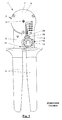
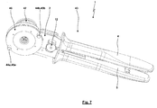
- Fig. 1 shows a pressing tongs 1 according to the prior art in its external appearance.
- the pressing pliers 1 has a pliers head 2 in which a fixed central lever 3, a fixed hand lever 4 and a movable hand lever 5 are rotatably supported relative to each other. Both hand lever 4, 5 are equipped with handles 6 made of elastomeric material.
- the fixed hand lever 4 is in the region of the pliers head 2 in a guide body 7 via (see also Fig. 2 and 3 ), which is covered by a cover plate 8.
- the guide body 7 and the cover plate 8 form with the fixed hand lever 4 a jointly moved part of the pressing tongs 1.
- the guide body 7 has an annular recess 9, in which a pivot ring 10 is pivotally mounted about the central axis 3.
- the pivot ring 10 is fixedly connected to the movable lever 5 or part of the same.
- a Zwangsgesperre 11 is interposed, which ensures that the respective pressing stroke of the crimping pliers 1 can only be performed completely and the crimping pliers only opens when the Zwangsgesperre 11 triggers or releases the opening stroke.
- an adjustment 12 is further provided on the fixed hand lever 4, which An essential part of the adjusting device 12 is an adjusting screw 13, which is rotatably mounted in pivot bearings 14, but not axially movable.
- the adjusting device 12 cooperates with an adjusting element 15, which in Fig. 3 and 4 can be seen.
- the adjusting element 15 is adjustably mounted on the fixed hand lever 4. For this purpose, it is guided in a recess 16 on the fixed hand lever 4.
- the depression 16 provides a circular arc-like contour around the central axis 3.
- the associated edge regions of the adjusting element 15 also have the shape of circular arcs about the central axis 3.
- the Zwangsgesperre 11 has essentially two parts, namely a toothed segment 17 and a rotatably mounted pawl 18.
- a Edge region of the adjusting element 15 is formed as a toothed segment 17.
- toothed segment 17 and pawl 18 of the Zwangsgesperres 11 are provided on different parts.
- the reverse arrangement could be provided by the toothed segment 17 is fixedly formed on the movable hand lever 5, while the pawl 18 would then be mounted on the adjusting element 15.
- the maximum compression of the two hand lever 4 and 5 is limited by an end position limit with a pair of stops.
- This pair of stops consists of a stop 19 and a counter-stop 20.
- the function of the stopper 19 and the counter-stop 20 is interchangeable, d. H. in itself it is arbitrary which part is called attack and counter-attack.
- the stop 19 can thus be formed on the adjusting element 15 or arranged on this.
- the stopper 19 is adjustable and adjustable in the same extent relative to the fixed hand lever 4, as is the toothed segment 17.
- the counter-stop 20 is, however, stationary housed or formed on the movable hand lever 5.
- the adjusting element 15 is plate-like.
- a slot 21 is provided in the central region of the adjusting element 15, a slot 21 is provided.
- An edge region of the elongated hole 21 is formed as a wedge surface 22.
- the wedge surface 22 is arranged at an angle which extends substantially obliquely to the main extension direction of the adjustment element 15 formed as a plate 23.
- the slot 21 is penetrated by a wedge 24.
- the wedge 24 is perpendicular to the main plane of extension of the plate 23 adjustable and has a wedge surface 25 which is associated with the wedge surface 22 of the adjusting element 15 and cooperates with this. Otherwise, the wedge 24 has a threaded bore 26.
- the wedge 24 is penetrated by the adjusting screw 13, which, as stated above, rotatably but not axially displaceably mounted in the pliers and has a corresponding mating thread to the thread of the bore 26 of the wedge 24. It already becomes recognizable that when turning the screw 13 of the adjusting 12 of the wedge 24 moves relative to the adjusting element 15, so that by the abutment of the two wedge surfaces 22 and 25 to each other a relative adjustment of the adjusting element 15 about the central axis 3 relative to the fixed hand lever 4 in the direction of movable hand lever 5 or contrary takes place. This direction of movement is indicated by a double arrow 27 in the Fig. 3 and 4 clarified.
- a pointer 28 is formed on the plate 23 of the adjusting element 15, which is provided with a scale 29 (FIG. Fig. 1 ) on the cover plate 8 and the fixed hand lever 4 cooperates.
- Fig. 1 also shows a marking for different offset depths in association with the scale 29.
- Fig. 3 to 6 let see more details of the pressing tongs.
- the ram 30 are mounted in radial guide slots 31 of the guide body 7 purely radially to the central axis 3 and thus to the fixed hand lever 4 slidably.
- the press punches 30 have at their free, the central axis 3 facing ends tips or pressing contours 32 which leave notches on the actuation of the pressing tongs 1 in a contact element not shown to be pressed, namely, as shown in the embodiment, four notches same press-fit.
- the number of ram 30 is at least three. But it can also be four (as shown) and more press ram 30 may be provided.
- the contact element which is usually designed as a sleeve and the thus to be pressed conductor into the recess forming a receptacle for the workpiece about the central axis 3 perpendicular to the plane of the drawing according to the Fig. 1 . 3 and 4 introduced and pressed in a known manner.
- the radial movement of the plunger 30 is divided into a forward stroke for pressing, in which the handles 4, 5 are compressed, and a reverse stroke in the reverse direction when opening the pressing pliers 1.
- the pivot ring 10 which with the movable handle 5 is associated, in association with each individual ram 30 depending on a cam surface or actuating surface 33 which cooperates with a corresponding counter-actuating surface 34 on each ram 30.
- the actuating surfaces 33 inclined are formed and arranged to the tangential circumferential direction of the pivot ring 10.
- the return stroke of the ram 30 is positively controlled and thus positive fit.
- the pivot ring 10 is provided with cam surfaces or actuating surfaces 35 which cooperate with corresponding counter-actuating surfaces 41 on the press dies 30, as can be seen from the drawings.
- the positively formed in this way return stroke of the ram 30 is particularly advantageous when the crimping pliers 1, for example, after a Fehlverpressung initially in the compressed position of the hand lever 4, 5 remains and the pressing contours 32 of the ram 30 have hooked in the contact element.
- an opening spring 36 is used for the opening stroke between the two hand levers 4 and 5, which may consist of a sleeve-like element in which a cylindrical compression spring is housed.
- the opening spring 36 is mounted or housed in the fixed hand lever 4.
- Fig. 3 can also recognize a bearing spring 37, which is designed here as a rod or leg spring.
- the task of the bearing spring 37 is to ensure at all times that the wedge surfaces 22 and 25 abut each other.
- Fig. 4 shows a representation similar to the pressing tongs according to the Fig. 1 to 3 , but in a modified embodiment.
- the press punches 30 are not shown, so that the formation of the guide body 7 with its recess in the central region is clearly visible.
- the pivot ring 10 is mounted, which is formed integrally with the movable lever 5.
- the open-edged recess for each of the press dies can be seen in each case an actuating surface 33 for the forward stroke and a further actuating surface 35 for the reverse stroke.
- the guide body 7 and the pivot ring 10 lie in a common plane of the main plane of extension of the pliers head 2, with the result that the height of the pliers head 2 is not increased by the arrangement of the pivot ring 10 and the ram 30.
- This embodiment is particularly suitable for pressing contact elements of small axial length and / or small diameter.
- Fig. 4 shows in comparison to Fig. 3 another division of the elements of the compulsory lock 11. While according to Fig. 3 the sector gear 17 was arranged on the fixed hand lever 4, is now in accordance Fig. 4 the toothed segment 17 fixed to the movable hand lever 5.
- the adjusting element 15 in the form of the plate 23 is still guided in a circular arc around the central axis 3 and adjustably mounted on the fixed hand lever 4. However, the adjusting element 15 is extended in the direction of the movable hand lever 5, to store the pawl 18 now rotatably on the adjusting element 15.
- the usual Einitatifeder for the pawl 18 and its suspension point on the adjusting element 15 are indicated.
- Fig. 4 is the set closed position of the pressing pliers 1 again, so that stop 19 and counter-stop 20 of the end position limit abut each other, as defined by the straight, infinitely set Endlagenbegrenzung.
- FIGS. 5 and 6 show a pliers head 2 detached from the special design of a drive. It is the guide body 7 recognizable with its annular recess 9, in which both the pivot ring 10 as well as the ram 30 are housed. Guide ring 10 and press punches 30 do not overlap in the projection, so that a particularly narrow construction ( Fig. 6 ) results. It is understood that the guide body 7 is connected to one part of the drive and the pivot ring 10 with the other part of the drive. Serve for this purpose bolts 38, which are geared, for example, connected to a movable hand lever 5. Also, the associated other hand lever 4 may be movably connected to the guide body 7.
- a positioner 42 may be mounted, which serves the exact positioning of the contact element to be pressed relative to the pliers head 2.
- Another generic crimping pliers of the Applicant is made DE 10 2005 003 617 B3 known.
- a base module of a pressing tongs can be operated with the hand levers with different nipper heads, wherein at least one nipper head is adapted for operation thereof with the removable cassette described below, while at least one further nipper head for any other purpose , in particular for a hand lever actuated pressing deviating functionality and / or for cutting, is used.
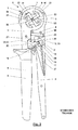
- a pressing tongs 1 according to the invention is shown, which with regard to the basic mode of operation until further notice the pressing tongs according to the Fig. 1 to 6 can correspond.
- the same reference numbers are used in part for this reason as for the embodiments according to FIG Fig. 1 to 6 if the components identified by the reference sign coincide at least partially with respect to their fundamental structural design, the geometry and / or their function.
- Fig. 7 shows the pressing tongs 1 with a fixed hand lever 4 and the movable hand lever 5.
- the pressing tongs is equipped with an adjusting device 12 and a positioner 42, wherein the adjusting device 12 and the positioner 42 each represent optional components of the pressing tongs 1.
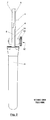
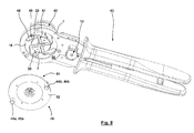
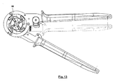
- Fig. 8 shows the removable cassette 46 separately from the base body 43 for dissolved fasteners 44.
- the main body 43 is formed in the region of the pliers head 2 with the guide body 7, which is associated with the fixed hand lever 4, and with the pivot ring 10 which is associated with the movable hand lever 5 ,
- Radially oriented guide slots 47 which the guide slots 31 according to Fig. 1 to 6 correspond, or guide grooves of the guide body 7 and recesses 48 form common, in the first rough approximation L-shaped receiving spaces 49.
- pressing tongs 1 with four press dies are four guide slots 47, four recesses 48 and four receiving spaces 49 evenly distributed in the circumferential direction.
- the receiving spaces 49 are in the region of the pivot ring 10 radially outwardly bounded by the actuating surfaces 33 and radially inwardly by the actuating surfaces 35, which are inclined relative to a tangential orientation, at least in some areas.
- the receiving spaces 49 are set back relative to a contact surface 50 of the main body 43 which is formed by the annular guide body 7 and faces the interchangeable cassette 46.
- the removable cassette 46 is formed with a main body 51.
- the main body 51 is formed in plate construction and has a circular ring disk 52 and a likewise annular guide plate 53.
- the circular disk 52 and the guide plate 53 are arranged coaxially with each other, wherein the inner diameter of the annular disc 52 is slightly smaller than the outer diameter of the guide plate 53, wherein Area of the cover formed in this way, the annular disc 52 with the guide plate 53 fasteners 54, the guide plate 53 rigidly connected to the circular disc 52.
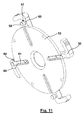
- the connecting elements 44a, 44b extend through recesses of the annular disk 52.
- the guide plate 53 has four outgoing from the edge 55 guide slots 56, which are radially inwardly closed. Radially outboard the guide slots 56 are covered in the assembled state by the overlap with the circular disk 52.
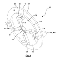
- Transverse to the main plane of extension of the four ram 30 extends from each ram 30 a carried by the ram 30 guide pin 57 which is screwed or pressed, for example, in the ram 30.
- the guide pin 57 has in the freely projecting from the ram 30 end portion a head 58 and arranged between the ram 30 and the head 58 guide portion 59th Wie Fig.
- the press ram 30 can be inserted from the outside into the guide slots 56, in which case a radial guidance of the guide pin 57 with the guide portion 59 in the guide slots 56 takes place.
- the guide plate 53 is then trapped between the ram 30 on the one hand and the head 58 of the guide pin 57, so that the ram 30 can be solved only by the guide plate 53 by the press ram 30 emerges with the guide pin 57 radially outward from the guide slot 56.
- the interior which is bounded by the contact surface 60 radially outward and is bounded on one side by the guide plate 53 and in which the heads 58 of the guide pin 57 move closed by a further annular disc 62, which from the outside to the Annular ring 52 is fixed in a manner not shown.
- the annular disc 62 has an inner bore which is arranged in alignment with the inner bore of the guide plate 53 and has a same diameter. Through these internal holes, the recording of the pressing tongs 1 can be accessible to the workpiece.
- the interchangeable cassette 46 is formed as a unit 63, in which the ram 30 are held captive, but have a degree of freedom for a radial displacement with the guide pin 57 along the guide slots 56.
- a contact surface 63 formed by the annular disk 52 comes into contact with the abutment surface 50, which is formed by the guide body 7, the pliers head 2 or the main body 43 of the pressing tongs 1.
- the guide plate 53 enters the inner bore of the annular guide body 7, wherein by the interaction of the cylindrical inner surface of the annular guide body 7 and the cylindrical outer surface 64th the guide plate 53 a guiding and / or centering effect can be brought about.
- the press punches 30 enter into the receiving spaces 49, whereby preferably already a contact of the actuating surfaces 33 of the swivel ring 10 with the counter-actuating surfaces 34 of the press ram 30 and / or the actuating surfaces 35 of the swivel ring 10 with the counter-actuating surfaces 41 of the punch 30 is brought about.
- the insertion can be assisted by suitable guiding or centering devices or bevels or phases.
- the ram 30 are held on the removable cassette in a predetermined radial mounting position, which can be accomplished by a spring element or a corresponding latching or holding element. In the mounted explained position, the operation of the pressing tongs can then be recorded.
- the assembly thus requires the approach of the removable cassette 46 to the body 43, the introduction of the ram 30 in the receiving spaces 49, the simultaneous entry of the guide plate 53 in the annular guide body, bringing about the abutment of the abutment surface 63 to the contact surface 50 and finally the fuse this mounting position on the connecting elements 44a, 44b.
- the disassembly is carried out by loosening the connecting elements 44a, 44b, which then as a unit, the removable cassette 46 can be removed from the main body 43 of the pressing tongs and the press ram 30 are removed from the receiving spaces 49 together.
- a connecting portion 65 of the removable cassette 46 is formed with the abutment surface 63 and the connecting elements 44.
- the counter-actuating surfaces 34, 41 of the ram 30 form a coupling region 66 of the removable cassette 46, via the mounted on the base 43 of the pressing tongs 1 exchange cassette 46, a transfer of operating forces in the opening and closing direction of the main body 43 to the removable cassette 46, namely takes place on the ram 30.
- Radially inwardly of the press dies 30, a receptacle 67 is formed for the workpiece. It is understood that this receptacle 67 extends through both the removable cassette 46 and the main body 43 of the pressing tongs 1, wherein the receptacle is formed in the assembled state by the interaction of the base body 43 with the removable cassette 46.
- the die halves are moved during the pressing in a single direction, namely along a translational degree of freedom or a pivoting degree of freedom, wherein for a direction sense, the opening movement is brought about, while for the other direction sense, a closing movement is brought about.
- the press punches 30 are moved in two, three or more directions.
- the movement is in each case of two opposing press dies 30 in the same direction, but with different sense of direction for the opening movement and for the closing movement, while the movement of the other two opposing ram 30 takes place in a direction which 90 ° is changed from the former direction.
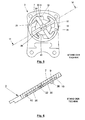
- Fig. 9 It is possible that several removable cassettes 46 according to Fig. 9 are arranged in a pressing tongs set. In this case, these exchangeable cassettes 46 can be a loose component of the pressing tongs set. It is also possible that for unused condition, the removable cassettes 46 with a protection, such as a protective cap, at least the in Fig. 9 Front side to protect the punches against damage and / or dirt covers, are equipped. It is also possible that several removable cassettes 46 for not used operating state in a common bracket or cover are used, which exerts the aforementioned protective function.
- a protection such as a protective cap
Landscapes
- Engineering & Computer Science (AREA)
- Manufacturing & Machinery (AREA)
- Manufacturing Of Electrical Connectors (AREA)
- Bending Of Plates, Rods, And Pipes (AREA)
- Mounting, Exchange, And Manufacturing Of Dies (AREA)
- Hand Tools For Fitting Together And Separating, Or Other Hand Tools (AREA)
Applications Claiming Priority (1)
| Application Number | Priority Date | Filing Date | Title |
|---|---|---|---|
| DE102011052967A DE102011052967B4 (de) | 2011-08-24 | 2011-08-24 | Presszange, Wechselkassette für eine Presszange und Presszangenset |
Publications (2)
| Publication Number | Publication Date |
|---|---|
| EP2562891A1 true EP2562891A1 (fr) | 2013-02-27 |
| EP2562891B1 EP2562891B1 (fr) | 2016-03-02 |
Family
ID=46650396
Family Applications (1)
| Application Number | Title | Priority Date | Filing Date |
|---|---|---|---|
| EP12179229.5A Not-in-force EP2562891B1 (fr) | 2011-08-24 | 2012-08-03 | Pince de pression |
Country Status (5)
| Country | Link |
|---|---|
| EP (1) | EP2562891B1 (fr) |
| JP (1) | JP2013043282A (fr) |
| CN (1) | CN102957078B (fr) |
| DE (1) | DE102011052967B4 (fr) |
| TW (1) | TWI579115B (fr) |
Cited By (5)
| Publication number | Priority date | Publication date | Assignee | Title |
|---|---|---|---|---|
| EP2995424A1 (fr) | 2014-09-11 | 2016-03-16 | Wezag GmbH Werkzeugfabrik | Pince |
| WO2016193053A3 (fr) * | 2015-05-29 | 2017-02-02 | Phoenix Contact Gmbh & Co. Kg | Outil de sertissage, de pressage ou de façonnage d'une pièce |
| DE202014011110U1 (de) | 2014-09-11 | 2017-11-29 | Wezag Gmbh Werkzeugfabrik | Handzange |
| US10355461B2 (en) | 2016-10-14 | 2019-07-16 | Wezag Gmbh Werkzeugfabrik | Stripping tool and method for stripping |
| US11837833B2 (en) * | 2020-12-18 | 2023-12-05 | Te Connectivity Solutions Gmbh | Terminal holding device for crimp hand tool |
Families Citing this family (6)
| Publication number | Priority date | Publication date | Assignee | Title |
|---|---|---|---|---|
| EP2905848B1 (fr) | 2014-02-06 | 2016-09-14 | Wezag GmbH Werkzeugfabrik | Pince de pression |
| EP3012924B1 (fr) * | 2014-10-20 | 2017-12-13 | Wezag GmbH Werkzeugfabrik | Pince de pression |
| EP3396796B1 (fr) | 2017-04-25 | 2021-07-21 | WEZAG GmbH & Co. KG | Outil de compression, de sertissage ou de découpe et module d'outils |
| DE102018101159A1 (de) * | 2017-12-01 | 2019-06-06 | Rennsteig Werkzeuge Gmbh | Pressbacken, sowie Presszange mit zwei Zangenbacken |
| EP4007087B1 (fr) | 2019-11-11 | 2024-02-07 | WEZAG GmbH & Co. KG | Pince à sertir |
| CN112467493B (zh) * | 2020-12-04 | 2022-04-19 | 广东电网有限责任公司江门供电局 | 一种电缆压接钳 |
Citations (11)
| Publication number | Priority date | Publication date | Assignee | Title |
|---|---|---|---|---|
| US2002502A (en) | 1932-12-15 | 1935-05-28 | Harry A Douglas | Swaging machine |
| US2991675A (en) * | 1958-11-10 | 1961-07-11 | Buchanan Electrical Prod Corp | Crimping tool |
| US3028776A (en) | 1959-06-04 | 1962-04-10 | Bendix Corp | Crimping tool with adjusting means |
| US3177695A (en) | 1963-05-23 | 1965-04-13 | Derk A Van Oort | Crimping tool for electrical and other connectors |
| DE20100031U1 (de) | 2001-01-02 | 2002-05-16 | Cimco Werkzeugfabrik Carl Jul | Presszange |
| US20040128818A1 (en) | 2002-08-31 | 2004-07-08 | Thomas Motsenbocker | Hand held stent crimping apparatus and method |
| DE10140270B4 (de) | 2001-08-16 | 2004-09-30 | Wezag Gmbh Werkzeugfabrik | Presszange zum Einpressen mehrerer Kerben auf dem Umfang eines Kontaktelementes |
| DE102005003617B3 (de) | 2005-01-26 | 2006-06-14 | Wezag Gmbh Werkzeugfabrik | Presszange zm Einpressen mehrerer Kerben auf dem Umfang eines Kontaktelementes |
| DE102005003615B3 (de) | 2005-01-26 | 2006-09-21 | Wezag Gmbh Werkzeugfabrik | Presszange zum Einpressen mehrerer Kerben auf dem Umfang eines Kontaktelementes |
| US7461448B2 (en) | 2005-08-17 | 2008-12-09 | Simon Schwartzman | Crimping tool with quick-change crimp head for sealing and electrically crimping electrical contacts to insulated wire |
| DE102008012011B3 (de) | 2008-03-01 | 2009-12-03 | Wezag Gmbh Werkzeugfabrik | Zangenkopf |
Family Cites Families (7)
| Publication number | Priority date | Publication date | Assignee | Title |
|---|---|---|---|---|
| US3080779A (en) * | 1961-05-02 | 1963-03-12 | Burndy Corp | Indenting tool |
| JPS5022277A (fr) * | 1973-07-02 | 1975-03-10 | ||
| JPH0718148Y2 (ja) * | 1989-02-04 | 1995-04-26 | アミテック株式会社 | 電線端子用手動圧着工具 |
| FR2873504B1 (fr) * | 2004-07-26 | 2007-04-13 | Airbus France Sas | Outil et procede de sertissage d'un contact sur un cable |
| DE202007013638U1 (de) * | 2007-09-28 | 2009-02-12 | Weidmüller Interface GmbH & Co. KG | Crimpvorrichtung für Kabel, insbesondere für Schirmkabel |
| CN201533100U (zh) * | 2009-09-23 | 2010-07-21 | 河南省电力公司商丘供电公司 | 一种压线工具 |
| TWM400897U (en) * | 2010-10-07 | 2011-04-01 | Chang-Yang Huang | Modified pipe seat structure of crimping pliers |
-
2011
- 2011-08-24 DE DE102011052967A patent/DE102011052967B4/de not_active Expired - Fee Related
-
2012
- 2012-08-03 EP EP12179229.5A patent/EP2562891B1/fr not_active Not-in-force
- 2012-08-09 TW TW101128736A patent/TWI579115B/zh not_active IP Right Cessation
- 2012-08-17 JP JP2012181181A patent/JP2013043282A/ja active Pending
- 2012-08-24 CN CN201210305797.7A patent/CN102957078B/zh not_active Expired - Fee Related
Patent Citations (12)
| Publication number | Priority date | Publication date | Assignee | Title |
|---|---|---|---|---|
| US2002502A (en) | 1932-12-15 | 1935-05-28 | Harry A Douglas | Swaging machine |
| US2991675A (en) * | 1958-11-10 | 1961-07-11 | Buchanan Electrical Prod Corp | Crimping tool |
| DE1136391B (de) | 1958-11-10 | 1962-09-13 | Buchanan Electrical Prod Corp | Werkzeug zum Kerben und Pressen elektrischer Klemmhuelsen |
| US3028776A (en) | 1959-06-04 | 1962-04-10 | Bendix Corp | Crimping tool with adjusting means |
| US3177695A (en) | 1963-05-23 | 1965-04-13 | Derk A Van Oort | Crimping tool for electrical and other connectors |
| DE20100031U1 (de) | 2001-01-02 | 2002-05-16 | Cimco Werkzeugfabrik Carl Jul | Presszange |
| DE10140270B4 (de) | 2001-08-16 | 2004-09-30 | Wezag Gmbh Werkzeugfabrik | Presszange zum Einpressen mehrerer Kerben auf dem Umfang eines Kontaktelementes |
| US20040128818A1 (en) | 2002-08-31 | 2004-07-08 | Thomas Motsenbocker | Hand held stent crimping apparatus and method |
| DE102005003617B3 (de) | 2005-01-26 | 2006-06-14 | Wezag Gmbh Werkzeugfabrik | Presszange zm Einpressen mehrerer Kerben auf dem Umfang eines Kontaktelementes |
| DE102005003615B3 (de) | 2005-01-26 | 2006-09-21 | Wezag Gmbh Werkzeugfabrik | Presszange zum Einpressen mehrerer Kerben auf dem Umfang eines Kontaktelementes |
| US7461448B2 (en) | 2005-08-17 | 2008-12-09 | Simon Schwartzman | Crimping tool with quick-change crimp head for sealing and electrically crimping electrical contacts to insulated wire |
| DE102008012011B3 (de) | 2008-03-01 | 2009-12-03 | Wezag Gmbh Werkzeugfabrik | Zangenkopf |
Cited By (7)
| Publication number | Priority date | Publication date | Assignee | Title |
|---|---|---|---|---|
| EP2995424A1 (fr) | 2014-09-11 | 2016-03-16 | Wezag GmbH Werkzeugfabrik | Pince |
| DE202014011110U1 (de) | 2014-09-11 | 2017-11-29 | Wezag Gmbh Werkzeugfabrik | Handzange |
| US9864948B2 (en) | 2014-09-11 | 2018-01-09 | Wezag Gmbh Werkzeugfabrik | Hand pliers |
| WO2016193053A3 (fr) * | 2015-05-29 | 2017-02-02 | Phoenix Contact Gmbh & Co. Kg | Outil de sertissage, de pressage ou de façonnage d'une pièce |
| US10173308B2 (en) | 2015-05-29 | 2019-01-08 | Phoenix Contact Gmbh & Co. Kg | Tool for crimping, pressing or forming a workpiece |
| US10355461B2 (en) | 2016-10-14 | 2019-07-16 | Wezag Gmbh Werkzeugfabrik | Stripping tool and method for stripping |
| US11837833B2 (en) * | 2020-12-18 | 2023-12-05 | Te Connectivity Solutions Gmbh | Terminal holding device for crimp hand tool |
Also Published As
| Publication number | Publication date |
|---|---|
| JP2013043282A (ja) | 2013-03-04 |
| CN102957078A (zh) | 2013-03-06 |
| DE102011052967A1 (de) | 2013-02-28 |
| DE102011052967B4 (de) | 2013-12-19 |
| TWI579115B (zh) | 2017-04-21 |
| EP2562891B1 (fr) | 2016-03-02 |
| CN102957078B (zh) | 2016-05-25 |
| TW201313402A (zh) | 2013-04-01 |
Similar Documents
| Publication | Publication Date | Title |
|---|---|---|
| EP2562891B1 (fr) | Pince de pression | |
| EP3012923B1 (fr) | Pince de pression | |
| EP2463969B1 (fr) | Tête de pince pour une pince de sertissage | |
| DE102008012011B3 (de) | Zangenkopf | |
| EP2873122B1 (fr) | Outil de sertissage pour douille d'extrêmité de conducteur | |
| EP3159088B1 (fr) | Pince manuelle | |
| EP1922787B1 (fr) | Outil de double sertissage | |
| EP2672580B1 (fr) | Tête de pince de sertissage | |
| EP3012924A1 (fr) | Pince de pression | |
| EP3904007B1 (fr) | Matrice de pince à sertir et pince à sertir | |
| EP2115829B1 (fr) | Dispositif de positionnement pour outils de sertissage | |
| EP2078591B1 (fr) | Outil de presse | |
| EP3300187A1 (fr) | Positionneur d'outil de presse et outil de presse | |
| EP3834989B1 (fr) | Outil pince à main et procédé de montage d'un tel outil | |
| EP3159107A1 (fr) | Groupe de pinces manuelles | |
| DE102013213265B3 (de) | Vorrichtung zur Bearbeitung eines Schirms eines Koaxialkabels | |
| DE102007005176B4 (de) | Positionierungseinrichtung für Crimpwerkzeuge | |
| DE102010024610B4 (de) | Setzgerät mit einer variablen Setzhubeinstellung | |
| EP2672581A1 (fr) | Pince de sertissage pour connecteur solaire avec aide au positionnement | |
| EP2777848B1 (fr) | Dispositif de serrage ou de préhension | |
| DE102010007917B4 (de) | Handbetätigtes Werkzeug | |
| EP3904006B1 (fr) | Matrice de pince à sertir et pince à sertir | |
| DE202018105955U1 (de) | Crimpkopf und Crimpwerkzeug | |
| EP2777850B1 (fr) | Dispositif de serrage ou de préhension | |
| EP2777849B1 (fr) | Dispositif de serrage ou de préhension |
Legal Events
| Date | Code | Title | Description |
|---|---|---|---|
| PUAI | Public reference made under article 153(3) epc to a published international application that has entered the european phase |
Free format text: ORIGINAL CODE: 0009012 |
|
| AK | Designated contracting states |
Kind code of ref document: A1 Designated state(s): AL AT BE BG CH CY CZ DE DK EE ES FI FR GB GR HR HU IE IS IT LI LT LU LV MC MK MT NL NO PL PT RO RS SE SI SK SM TR |
|
| AX | Request for extension of the european patent |
Extension state: BA ME |
|
| 17P | Request for examination filed |
Effective date: 20130314 |
|
| GRAP | Despatch of communication of intention to grant a patent |
Free format text: ORIGINAL CODE: EPIDOSNIGR1 |
|
| INTG | Intention to grant announced |
Effective date: 20150909 |
|
| GRAS | Grant fee paid |
Free format text: ORIGINAL CODE: EPIDOSNIGR3 |
|
| GRAA | (expected) grant |
Free format text: ORIGINAL CODE: 0009210 |
|
| AK | Designated contracting states |
Kind code of ref document: B1 Designated state(s): AL AT BE BG CH CY CZ DE DK EE ES FI FR GB GR HR HU IE IS IT LI LT LU LV MC MK MT NL NO PL PT RO RS SE SI SK SM TR |
|
| REG | Reference to a national code |
Ref country code: GB Ref legal event code: FG4D Free format text: NOT ENGLISH |
|
| REG | Reference to a national code |
Ref country code: AT Ref legal event code: REF Ref document number: 778594 Country of ref document: AT Kind code of ref document: T Effective date: 20160315 Ref country code: CH Ref legal event code: EP |
|
| REG | Reference to a national code |
Ref country code: IE Ref legal event code: FG4D Free format text: LANGUAGE OF EP DOCUMENT: GERMAN |
|
| REG | Reference to a national code |
Ref country code: CH Ref legal event code: NV Representative=s name: RIEDERER HASLER AND PARTNER PATENTANWAELTE AG, LI |
|
| REG | Reference to a national code |
Ref country code: DE Ref legal event code: R096 Ref document number: 502012006098 Country of ref document: DE |
|
| REG | Reference to a national code |
Ref country code: SE Ref legal event code: TRGR |
|
| REG | Reference to a national code |
Ref country code: NL Ref legal event code: MP Effective date: 20160302 |
|
| REG | Reference to a national code |
Ref country code: LT Ref legal event code: MG4D |
|
| PG25 | Lapsed in a contracting state [announced via postgrant information from national office to epo] |
Ref country code: NO Free format text: LAPSE BECAUSE OF FAILURE TO SUBMIT A TRANSLATION OF THE DESCRIPTION OR TO PAY THE FEE WITHIN THE PRESCRIBED TIME-LIMIT Effective date: 20160602 Ref country code: FI Free format text: LAPSE BECAUSE OF FAILURE TO SUBMIT A TRANSLATION OF THE DESCRIPTION OR TO PAY THE FEE WITHIN THE PRESCRIBED TIME-LIMIT Effective date: 20160302 Ref country code: HR Free format text: LAPSE BECAUSE OF FAILURE TO SUBMIT A TRANSLATION OF THE DESCRIPTION OR TO PAY THE FEE WITHIN THE PRESCRIBED TIME-LIMIT Effective date: 20160302 Ref country code: GR Free format text: LAPSE BECAUSE OF FAILURE TO SUBMIT A TRANSLATION OF THE DESCRIPTION OR TO PAY THE FEE WITHIN THE PRESCRIBED TIME-LIMIT Effective date: 20160603 Ref country code: ES Free format text: LAPSE BECAUSE OF FAILURE TO SUBMIT A TRANSLATION OF THE DESCRIPTION OR TO PAY THE FEE WITHIN THE PRESCRIBED TIME-LIMIT Effective date: 20160302 |
|
| PG25 | Lapsed in a contracting state [announced via postgrant information from national office to epo] |
Ref country code: LV Free format text: LAPSE BECAUSE OF FAILURE TO SUBMIT A TRANSLATION OF THE DESCRIPTION OR TO PAY THE FEE WITHIN THE PRESCRIBED TIME-LIMIT Effective date: 20160302 Ref country code: PL Free format text: LAPSE BECAUSE OF FAILURE TO SUBMIT A TRANSLATION OF THE DESCRIPTION OR TO PAY THE FEE WITHIN THE PRESCRIBED TIME-LIMIT Effective date: 20160302 Ref country code: RS Free format text: LAPSE BECAUSE OF FAILURE TO SUBMIT A TRANSLATION OF THE DESCRIPTION OR TO PAY THE FEE WITHIN THE PRESCRIBED TIME-LIMIT Effective date: 20160302 Ref country code: NL Free format text: LAPSE BECAUSE OF FAILURE TO SUBMIT A TRANSLATION OF THE DESCRIPTION OR TO PAY THE FEE WITHIN THE PRESCRIBED TIME-LIMIT Effective date: 20160302 Ref country code: LT Free format text: LAPSE BECAUSE OF FAILURE TO SUBMIT A TRANSLATION OF THE DESCRIPTION OR TO PAY THE FEE WITHIN THE PRESCRIBED TIME-LIMIT Effective date: 20160302 |
|
| PG25 | Lapsed in a contracting state [announced via postgrant information from national office to epo] |
Ref country code: IS Free format text: LAPSE BECAUSE OF FAILURE TO SUBMIT A TRANSLATION OF THE DESCRIPTION OR TO PAY THE FEE WITHIN THE PRESCRIBED TIME-LIMIT Effective date: 20160702 Ref country code: EE Free format text: LAPSE BECAUSE OF FAILURE TO SUBMIT A TRANSLATION OF THE DESCRIPTION OR TO PAY THE FEE WITHIN THE PRESCRIBED TIME-LIMIT Effective date: 20160302 |
|
| PG25 | Lapsed in a contracting state [announced via postgrant information from national office to epo] |
Ref country code: CZ Free format text: LAPSE BECAUSE OF FAILURE TO SUBMIT A TRANSLATION OF THE DESCRIPTION OR TO PAY THE FEE WITHIN THE PRESCRIBED TIME-LIMIT Effective date: 20160302 Ref country code: SK Free format text: LAPSE BECAUSE OF FAILURE TO SUBMIT A TRANSLATION OF THE DESCRIPTION OR TO PAY THE FEE WITHIN THE PRESCRIBED TIME-LIMIT Effective date: 20160302 Ref country code: PT Free format text: LAPSE BECAUSE OF FAILURE TO SUBMIT A TRANSLATION OF THE DESCRIPTION OR TO PAY THE FEE WITHIN THE PRESCRIBED TIME-LIMIT Effective date: 20160704 Ref country code: SM Free format text: LAPSE BECAUSE OF FAILURE TO SUBMIT A TRANSLATION OF THE DESCRIPTION OR TO PAY THE FEE WITHIN THE PRESCRIBED TIME-LIMIT Effective date: 20160302 Ref country code: RO Free format text: LAPSE BECAUSE OF FAILURE TO SUBMIT A TRANSLATION OF THE DESCRIPTION OR TO PAY THE FEE WITHIN THE PRESCRIBED TIME-LIMIT Effective date: 20160302 |
|
| REG | Reference to a national code |
Ref country code: DE Ref legal event code: R097 Ref document number: 502012006098 Country of ref document: DE |
|
| PG25 | Lapsed in a contracting state [announced via postgrant information from national office to epo] |
Ref country code: BE Free format text: LAPSE BECAUSE OF NON-PAYMENT OF DUE FEES Effective date: 20160831 Ref country code: IT Free format text: LAPSE BECAUSE OF FAILURE TO SUBMIT A TRANSLATION OF THE DESCRIPTION OR TO PAY THE FEE WITHIN THE PRESCRIBED TIME-LIMIT Effective date: 20160302 |
|
| PLBE | No opposition filed within time limit |
Free format text: ORIGINAL CODE: 0009261 |
|
| STAA | Information on the status of an ep patent application or granted ep patent |
Free format text: STATUS: NO OPPOSITION FILED WITHIN TIME LIMIT |
|
| PG25 | Lapsed in a contracting state [announced via postgrant information from national office to epo] |
Ref country code: DK Free format text: LAPSE BECAUSE OF FAILURE TO SUBMIT A TRANSLATION OF THE DESCRIPTION OR TO PAY THE FEE WITHIN THE PRESCRIBED TIME-LIMIT Effective date: 20160302 |
|
| 26N | No opposition filed |
Effective date: 20161205 |
|
| PG25 | Lapsed in a contracting state [announced via postgrant information from national office to epo] |
Ref country code: BG Free format text: LAPSE BECAUSE OF FAILURE TO SUBMIT A TRANSLATION OF THE DESCRIPTION OR TO PAY THE FEE WITHIN THE PRESCRIBED TIME-LIMIT Effective date: 20160602 Ref country code: SI Free format text: LAPSE BECAUSE OF FAILURE TO SUBMIT A TRANSLATION OF THE DESCRIPTION OR TO PAY THE FEE WITHIN THE PRESCRIBED TIME-LIMIT Effective date: 20160302 |
|
| PG25 | Lapsed in a contracting state [announced via postgrant information from national office to epo] |
Ref country code: MC Free format text: LAPSE BECAUSE OF FAILURE TO SUBMIT A TRANSLATION OF THE DESCRIPTION OR TO PAY THE FEE WITHIN THE PRESCRIBED TIME-LIMIT Effective date: 20160302 |
|
| REG | Reference to a national code |
Ref country code: FR Ref legal event code: ST Effective date: 20170428 |
|
| REG | Reference to a national code |
Ref country code: IE Ref legal event code: MM4A |
|
| PG25 | Lapsed in a contracting state [announced via postgrant information from national office to epo] |
Ref country code: IE Free format text: LAPSE BECAUSE OF NON-PAYMENT OF DUE FEES Effective date: 20160803 Ref country code: FR Free format text: LAPSE BECAUSE OF NON-PAYMENT OF DUE FEES Effective date: 20160831 |
|
| PG25 | Lapsed in a contracting state [announced via postgrant information from national office to epo] |
Ref country code: LU Free format text: LAPSE BECAUSE OF NON-PAYMENT OF DUE FEES Effective date: 20160803 |
|
| PGFP | Annual fee paid to national office [announced via postgrant information from national office to epo] |
Ref country code: CH Payment date: 20170830 Year of fee payment: 6 Ref country code: GB Payment date: 20170824 Year of fee payment: 6 Ref country code: DE Payment date: 20170518 Year of fee payment: 6 |
|
| PGFP | Annual fee paid to national office [announced via postgrant information from national office to epo] |
Ref country code: TR Payment date: 20170801 Year of fee payment: 6 Ref country code: AT Payment date: 20170821 Year of fee payment: 6 Ref country code: SE Payment date: 20170830 Year of fee payment: 6 |
|
| PG25 | Lapsed in a contracting state [announced via postgrant information from national office to epo] |
Ref country code: HU Free format text: LAPSE BECAUSE OF FAILURE TO SUBMIT A TRANSLATION OF THE DESCRIPTION OR TO PAY THE FEE WITHIN THE PRESCRIBED TIME-LIMIT; INVALID AB INITIO Effective date: 20120803 Ref country code: CY Free format text: LAPSE BECAUSE OF FAILURE TO SUBMIT A TRANSLATION OF THE DESCRIPTION OR TO PAY THE FEE WITHIN THE PRESCRIBED TIME-LIMIT Effective date: 20160302 |
|
| PG25 | Lapsed in a contracting state [announced via postgrant information from national office to epo] |
Ref country code: MK Free format text: LAPSE BECAUSE OF FAILURE TO SUBMIT A TRANSLATION OF THE DESCRIPTION OR TO PAY THE FEE WITHIN THE PRESCRIBED TIME-LIMIT Effective date: 20160302 Ref country code: MT Free format text: LAPSE BECAUSE OF FAILURE TO SUBMIT A TRANSLATION OF THE DESCRIPTION OR TO PAY THE FEE WITHIN THE PRESCRIBED TIME-LIMIT Effective date: 20160302 |
|
| PG25 | Lapsed in a contracting state [announced via postgrant information from national office to epo] |
Ref country code: AL Free format text: LAPSE BECAUSE OF FAILURE TO SUBMIT A TRANSLATION OF THE DESCRIPTION OR TO PAY THE FEE WITHIN THE PRESCRIBED TIME-LIMIT Effective date: 20160302 |
|
| REG | Reference to a national code |
Ref country code: DE Ref legal event code: R119 Ref document number: 502012006098 Country of ref document: DE |
|
| REG | Reference to a national code |
Ref country code: CH Ref legal event code: PL |
|
| REG | Reference to a national code |
Ref country code: SE Ref legal event code: EUG |
|
| REG | Reference to a national code |
Ref country code: AT Ref legal event code: MM01 Ref document number: 778594 Country of ref document: AT Kind code of ref document: T Effective date: 20180803 |
|
| GBPC | Gb: european patent ceased through non-payment of renewal fee |
Effective date: 20180803 |
|
| PG25 | Lapsed in a contracting state [announced via postgrant information from national office to epo] |
Ref country code: LI Free format text: LAPSE BECAUSE OF NON-PAYMENT OF DUE FEES Effective date: 20180831 Ref country code: CH Free format text: LAPSE BECAUSE OF NON-PAYMENT OF DUE FEES Effective date: 20180831 Ref country code: AT Free format text: LAPSE BECAUSE OF NON-PAYMENT OF DUE FEES Effective date: 20180803 |
|
| PG25 | Lapsed in a contracting state [announced via postgrant information from national office to epo] |
Ref country code: SE Free format text: LAPSE BECAUSE OF NON-PAYMENT OF DUE FEES Effective date: 20180804 |
|
| PG25 | Lapsed in a contracting state [announced via postgrant information from national office to epo] |
Ref country code: DE Free format text: LAPSE BECAUSE OF NON-PAYMENT OF DUE FEES Effective date: 20190301 |
|
| PG25 | Lapsed in a contracting state [announced via postgrant information from national office to epo] |
Ref country code: GB Free format text: LAPSE BECAUSE OF NON-PAYMENT OF DUE FEES Effective date: 20180803 |
|
| PG25 | Lapsed in a contracting state [announced via postgrant information from national office to epo] |
Ref country code: TR Free format text: LAPSE BECAUSE OF NON-PAYMENT OF DUE FEES Effective date: 20180803 |