EP2562425A2 - Turbomaschine - Google Patents
Turbomaschine Download PDFInfo
- Publication number
- EP2562425A2 EP2562425A2 EP12181315A EP12181315A EP2562425A2 EP 2562425 A2 EP2562425 A2 EP 2562425A2 EP 12181315 A EP12181315 A EP 12181315A EP 12181315 A EP12181315 A EP 12181315A EP 2562425 A2 EP2562425 A2 EP 2562425A2
- Authority
- EP
- European Patent Office
- Prior art keywords
- turbomachine
- assembly
- inlet
- flange
- housing
- Prior art date
- Legal status (The legal status is an assumption and is not a legal conclusion. Google has not performed a legal analysis and makes no representation as to the accuracy of the status listed.)
- Withdrawn
Links
- 239000007788 liquid Substances 0.000 description 5
- 238000004804 winding Methods 0.000 description 5
- 238000004519 manufacturing process Methods 0.000 description 2
- RYGMFSIKBFXOCR-UHFFFAOYSA-N Copper Chemical compound [Cu] RYGMFSIKBFXOCR-UHFFFAOYSA-N 0.000 description 1
- 238000001816 cooling Methods 0.000 description 1
- 229910052802 copper Inorganic materials 0.000 description 1
- 239000010949 copper Substances 0.000 description 1
- 239000012530 fluid Substances 0.000 description 1
Images


Classifications
-
- F—MECHANICAL ENGINEERING; LIGHTING; HEATING; WEAPONS; BLASTING
- F04—POSITIVE - DISPLACEMENT MACHINES FOR LIQUIDS; PUMPS FOR LIQUIDS OR ELASTIC FLUIDS
- F04D—NON-POSITIVE-DISPLACEMENT PUMPS
- F04D25/00—Pumping installations or systems
- F04D25/02—Units comprising pumps and their driving means
- F04D25/06—Units comprising pumps and their driving means the pump being electrically driven
- F04D25/0606—Units comprising pumps and their driving means the pump being electrically driven the electric motor being specially adapted for integration in the pump
-
- F—MECHANICAL ENGINEERING; LIGHTING; HEATING; WEAPONS; BLASTING
- F04—POSITIVE - DISPLACEMENT MACHINES FOR LIQUIDS; PUMPS FOR LIQUIDS OR ELASTIC FLUIDS
- F04D—NON-POSITIVE-DISPLACEMENT PUMPS
- F04D25/00—Pumping installations or systems
- F04D25/02—Units comprising pumps and their driving means
- F04D25/06—Units comprising pumps and their driving means the pump being electrically driven
-
- F—MECHANICAL ENGINEERING; LIGHTING; HEATING; WEAPONS; BLASTING
- F04—POSITIVE - DISPLACEMENT MACHINES FOR LIQUIDS; PUMPS FOR LIQUIDS OR ELASTIC FLUIDS
- F04D—NON-POSITIVE-DISPLACEMENT PUMPS
- F04D25/00—Pumping installations or systems
- F04D25/02—Units comprising pumps and their driving means
- F04D25/08—Units comprising pumps and their driving means the working fluid being air, e.g. for ventilation
- F04D25/082—Units comprising pumps and their driving means the working fluid being air, e.g. for ventilation the unit having provision for cooling the motor
-
- F—MECHANICAL ENGINEERING; LIGHTING; HEATING; WEAPONS; BLASTING
- F04—POSITIVE - DISPLACEMENT MACHINES FOR LIQUIDS; PUMPS FOR LIQUIDS OR ELASTIC FLUIDS
- F04D—NON-POSITIVE-DISPLACEMENT PUMPS
- F04D29/00—Details, component parts, or accessories
- F04D29/58—Cooling; Heating; Diminishing heat transfer
- F04D29/5806—Cooling the drive system
-
- F—MECHANICAL ENGINEERING; LIGHTING; HEATING; WEAPONS; BLASTING
- F04—POSITIVE - DISPLACEMENT MACHINES FOR LIQUIDS; PUMPS FOR LIQUIDS OR ELASTIC FLUIDS
- F04D—NON-POSITIVE-DISPLACEMENT PUMPS
- F04D29/00—Details, component parts, or accessories
- F04D29/58—Cooling; Heating; Diminishing heat transfer
- F04D29/5813—Cooling the control unit
-
- F—MECHANICAL ENGINEERING; LIGHTING; HEATING; WEAPONS; BLASTING
- F04—POSITIVE - DISPLACEMENT MACHINES FOR LIQUIDS; PUMPS FOR LIQUIDS OR ELASTIC FLUIDS
- F04D—NON-POSITIVE-DISPLACEMENT PUMPS
- F04D29/00—Details, component parts, or accessories
- F04D29/58—Cooling; Heating; Diminishing heat transfer
- F04D29/582—Cooling; Heating; Diminishing heat transfer specially adapted for elastic fluid pumps
- F04D29/584—Cooling; Heating; Diminishing heat transfer specially adapted for elastic fluid pumps cooling or heating the machine
-
- H—ELECTRICITY
- H02—GENERATION; CONVERSION OR DISTRIBUTION OF ELECTRIC POWER
- H02K—DYNAMO-ELECTRIC MACHINES
- H02K9/00—Arrangements for cooling or ventilating
- H02K9/02—Arrangements for cooling or ventilating by ambient air flowing through the machine
- H02K9/04—Arrangements for cooling or ventilating by ambient air flowing through the machine having means for generating a flow of cooling medium
- H02K9/06—Arrangements for cooling or ventilating by ambient air flowing through the machine having means for generating a flow of cooling medium with fans or impellers driven by the machine shaft
Definitions
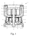
- the turbomachine 1 of Figures 1 and 2 comprises a housing 2, a rotor assembly 3, a stator assembly 4, and a circuit assembly 5.
- the circuit assembly 5 comprises a circuit board 21 and a plurality of electrical components 22.
- the electrical components 21 are a toroidal inductor 23 and four power switches 24 (e.g. BJT, MOSFET, IGBT).
- the inductor 23 surrounds the rotor assembly 3 and is located between the stator assembly 4 and the impeller 16. The winding of the inductor 23 then extends axially past the stator assembly 4 and is electrically coupled to the circuit board 21.
- the four power switches 24 control the delivery of electrical power to the phase winding of the stator assembly 4. More particularly, the power switches 24 are arranged as an H-bridge that is coupled to the phase winding.
- Each of the power switches 24 comprises a heat sink 25.
- the circuit assembly 5 is located adjacent the upper cover 7. Moreover, the circuit board 21 surrounds the flange 10 and includes an aperture 26 through which the flange 10 extends. The flange 10 thus extends axially beyond the circuit board 21.
- the heat sink 25 of each power switch 24 extends axially beyond the flange 10. More particularly, each heat sink 25 extends axially along a side of the stator assembly 4.
- the impeller 16 draws a working airflow into the housing 2 via the inlet 9. Owing to the location of the impeller 16 within the housing 2, the airflow moves generally axially through the housing 2 from the inlet 9 to the impeller 16. As the airflow moves through the housing 2, the airflow passes over the stator assembly 4 and the heat sinks 25. The airflow thus acts to cool the stator assembly 4 and the power switches 24.
- the stator assembly 4 comprises a pair of opposing stator cores 19, each of which is generally c-shaped. Accordingly, the overall shape of the stator assembly 4 is elongated. The inlet 9 is therefore similarly elongated such that the airflow is better directed to the stator assembly 4.
- the flange 10 acts to screen the circuit board 21 from the working airflow. Since the flange 10 extends axially beyond the circuit board 21 and the airflow moves generally axially through the housing 2, a region of dead space is effectively created at the surface of the circuit board 21. Accordingly, should any liquid be carried inadvertently by the working airflow, there is less risk of the liquid finding its way onto the circuit board 21. Although the circuit board 21 is not directly exposed to the working airflow, the heat sinks 25 are. Consequently, the power switches 24 continue to be cooled in spite of the fact that the circuit board 21 is better protected.
- the circuit assembly 5 comprises a large number of electrical components 22 mounted on the circuit board 21.
- a circuit board 21 that surrounds the flange 10 good use is made of the available space and thus a more compact turbomachine 1 may be realised.
- a single circuit board 21 may be employed for the circuit assembly 5. This then simplifies the manufacture and assembly of the turbomachine 1.
- the circuit assembly 5 were to comprise two smaller circuit boards located on opposite sides of the flange 10, electrical connections would then be required between the two boards.
- the shaft 13 and the rotor core 14 of the rotor assembly 3, along with the stator assembly 4 and the circuit assembly 5, may be collectively regarded as a motor that drives the impeller 16.
- these components may collectively take the form of a generator that is driven by the impeller 16.
- the turbomachine 1 may be said to comprise an electrical machine that drives or is driven by an impeller 16.
- the circuit assembly 5 then comprises at least one power switch 24 for controlling electrical power to or from the electrical machine.
- the electrical machine takes the form of a brushless DC motor. Alternatively, however, the electrical machine may be brushed and/or driven by an AC voltage.
Landscapes
- Engineering & Computer Science (AREA)
- Mechanical Engineering (AREA)
- General Engineering & Computer Science (AREA)
- Physics & Mathematics (AREA)
- Thermal Sciences (AREA)
- Power Engineering (AREA)
- Structures Of Non-Positive Displacement Pumps (AREA)
- Motor Or Generator Frames (AREA)
- Connection Of Motors, Electrical Generators, Mechanical Devices, And The Like (AREA)
- Cooling Or The Like Of Electrical Apparatus (AREA)
- Motor Or Generator Cooling System (AREA)
Applications Claiming Priority (1)
| Application Number | Priority Date | Filing Date | Title |
|---|---|---|---|
| GB1114788.1A GB2493975B (en) | 2011-08-26 | 2011-08-26 | Turbomachine |
Publications (2)
| Publication Number | Publication Date |
|---|---|
| EP2562425A2 true EP2562425A2 (de) | 2013-02-27 |
| EP2562425A3 EP2562425A3 (de) | 2016-02-24 |
Family
ID=44838779
Family Applications (1)
| Application Number | Title | Priority Date | Filing Date |
|---|---|---|---|
| EP12181315.8A Withdrawn EP2562425A3 (de) | 2011-08-26 | 2012-08-22 | Turbomaschine |
Country Status (4)
| Country | Link |
|---|---|
| US (1) | US9169843B2 (de) |
| EP (1) | EP2562425A3 (de) |
| JP (1) | JP5650176B2 (de) |
| GB (1) | GB2493975B (de) |
Cited By (4)
| Publication number | Priority date | Publication date | Assignee | Title |
|---|---|---|---|---|
| EP2903141A3 (de) * | 2014-01-29 | 2016-07-06 | Samsung Electronics Co., Ltd | Motor |
| EP3151385A4 (de) * | 2014-05-28 | 2018-01-24 | Kingclean Electric Co., Ltd. | Rotor sowie verarbeitungs- und montageverfahren dafür |
| EP3387741B1 (de) * | 2015-12-11 | 2020-04-29 | Dyson Technology Limited | Ein elektromotor |
| WO2024002469A1 (de) * | 2022-06-28 | 2024-01-04 | Pierburg Gmbh | Gebläse |
Families Citing this family (16)
| Publication number | Priority date | Publication date | Assignee | Title |
|---|---|---|---|---|
| GB2493976B (en) * | 2011-08-26 | 2014-08-13 | Dyson Technology Ltd | Turbomachine |
| US20180058464A1 (en) * | 2016-08-24 | 2018-03-01 | Q.E.D. Environmental Systems, Inc. | Pump Having Edge Mounted O-Ring Seal |
| CN106481588B (zh) * | 2016-11-16 | 2018-09-25 | 深圳拓邦股份有限公司 | 吸尘器及风机 |
| US11274679B2 (en) * | 2017-02-14 | 2022-03-15 | Danfoss A/S | Oil free centrifugal compressor for use in low capacity applications |
| US10718105B2 (en) | 2017-03-02 | 2020-07-21 | Kohler Co. | Handwashing station |
| GB2563624B (en) * | 2017-06-20 | 2020-04-08 | Dyson Technology Ltd | A compressor |
| GB2563617B (en) | 2017-06-20 | 2020-04-08 | Dyson Technology Ltd | An electric machine |
| GB2568979A (en) * | 2017-12-01 | 2019-06-05 | Dyson Technology Ltd | A fan assembly |
| GB2568939B (en) | 2017-12-01 | 2020-12-02 | Dyson Technology Ltd | A fan assembly |
| WO2019180936A1 (ja) | 2018-03-23 | 2019-09-26 | 三菱電機株式会社 | 電動送風機、電気掃除機および手乾燥装置 |
| CN108869407A (zh) * | 2018-06-20 | 2018-11-23 | 广东美的白色家电技术创新中心有限公司 | 一种排气消声装置及家电设备 |
| CN210053306U (zh) * | 2019-06-03 | 2020-02-11 | 东莞福莱仕智能电子科技有限公司 | 吸尘器马达装置和吸尘器 |
| CN110635623B (zh) * | 2019-10-28 | 2025-11-14 | 江苏雷利电机股份有限公司 | 具有散热结构的开关磁阻电机及含该电机的电动园林工具 |
| GB2608836C (en) * | 2021-07-13 | 2024-06-05 | Dyson Technology Ltd | A brushless motor |
| KR20230101428A (ko) * | 2021-12-29 | 2023-07-06 | 삼성전자주식회사 | 청소기용 모터 어셈블리 |
| DE102023210202A1 (de) * | 2023-10-18 | 2025-04-24 | Zf Cv Systems Global Gmbh | Gebläse für eine Brennstoffzellenanordnung |
Citations (1)
| Publication number | Priority date | Publication date | Assignee | Title |
|---|---|---|---|---|
| US20080283216A1 (en) * | 2007-05-14 | 2008-11-20 | Sunonwealth Electric Machine Industry Co., Ltd. | Cooling device |
Family Cites Families (30)
| Publication number | Priority date | Publication date | Assignee | Title |
|---|---|---|---|---|
| US3271601A (en) * | 1961-09-28 | 1966-09-06 | Gen Motors Corp | Dynamoelectric machine |
| US3407995A (en) * | 1966-10-12 | 1968-10-29 | Lau Blower Co | Blower assembly |
| US4255684A (en) * | 1979-08-03 | 1981-03-10 | Mischler William R | Laminated motor stator structure with molded composite pole pieces |
| US4513812A (en) * | 1981-06-25 | 1985-04-30 | Papst-Motoren Gmbh & Co. Kg | Heat sink for electronic devices |
| DE3137981C2 (de) | 1981-09-24 | 1986-01-16 | Licentia Patent-Verwaltungs-Gmbh, 6000 Frankfurt | Verfahren zur zentrischen Befestigung eines ringförmigen Körpers auf einer Welle |
| JPS6165865U (de) * | 1984-10-03 | 1986-05-06 | ||
| US4659951A (en) * | 1986-02-14 | 1987-04-21 | General Motors Corporation | Brushless blower motor with load proportional cooling for control circuitry |
| DE4038775A1 (de) | 1990-12-05 | 1992-06-11 | Klaus Reinhardt | Ventilator |
| US5316440A (en) | 1991-05-10 | 1994-05-31 | Terumo Kabushiki Kaisha | Blood pump apparatus |
| KR970001995A (ko) | 1995-06-29 | 1997-01-24 | 배순훈 | 온수순환펌프 |
| EP0810511B1 (de) * | 1996-05-14 | 2003-11-12 | Hewlett-Packard Company, A Delaware Corporation | Einrichtung zur Kühlung von Komponenten in einem elektrischen Gerät mit interner Stromversorgungseinheit |
| DK0901442T3 (da) | 1996-05-28 | 2000-11-20 | Daimler Chrysler Ag | Fremgangsmåde til sammenføjning af komponenter og moduler i skinnekøretøjer ved klæbning |
| US5904471A (en) * | 1996-12-20 | 1999-05-18 | Turbodyne Systems, Inc. | Cooling means for a motor-driven centrifugal air compressor |
| DE19727165A1 (de) * | 1997-06-26 | 1999-01-07 | Bosch Gmbh Robert | Elektrischer Antriebsmotor |
| US6439845B1 (en) | 2000-03-23 | 2002-08-27 | Kidney Replacement Services, P.C. | Blood pump |
| US6413039B1 (en) | 2000-06-01 | 2002-07-02 | Uis, Inc | Impeller for coolant pumps |
| FR2827345A1 (fr) * | 2001-07-13 | 2003-01-17 | Sagem | Motoventilateur a carte de commande integree |
| US20040170497A1 (en) | 2003-02-27 | 2004-09-02 | Daniel Snyder | Beltless high velocity air blower |
| SG121838A1 (en) | 2003-12-05 | 2006-05-26 | Singapore Technologies Marine | Composite drive shaft |
| JP4631382B2 (ja) * | 2004-10-04 | 2011-02-16 | 日本電産株式会社 | ブラシレスモータ |
| DE202005004274U1 (de) * | 2005-03-14 | 2006-07-27 | Ebm-Papst Landshut Gmbh | Elektromotorisch angetriebenes Radialgebläse mit IC |
| US20060226718A1 (en) * | 2005-04-08 | 2006-10-12 | Tai-Her Yang | Closed enclosure electric machine |
| JP4116644B2 (ja) * | 2006-01-25 | 2008-07-09 | 三菱電機株式会社 | 制御装置一体型回転電機 |
| TW200740085A (en) * | 2006-04-13 | 2007-10-16 | Sunonwealth Electr Mach Ind Co | Heat dissipation structure for base of motor |
| JP4797779B2 (ja) * | 2006-04-27 | 2011-10-19 | 株式会社デンソー | 車両用交流発電機 |
| GB2467964B (en) | 2009-02-24 | 2015-03-25 | Dyson Technology Ltd | Shroud-Diffuser assembly |
| GB2467969B (en) | 2009-02-24 | 2013-06-12 | Dyson Technology Ltd | Bearing support |
| GB2467967B (en) | 2009-02-24 | 2015-04-22 | Dyson Technology Ltd | Rotor assembly |
| EP2236838B1 (de) * | 2009-03-25 | 2016-09-21 | ebm-papst Mulfingen GmbH & Co. KG | Radialgebläse |
| JP2011064118A (ja) | 2009-09-16 | 2011-03-31 | Mitsubishi Heavy Ind Ltd | 遠心圧縮機 |
-
2011
- 2011-08-26 GB GB1114788.1A patent/GB2493975B/en active Active
-
2012
- 2012-08-22 EP EP12181315.8A patent/EP2562425A3/de not_active Withdrawn
- 2012-08-24 US US13/594,392 patent/US9169843B2/en active Active
- 2012-08-24 JP JP2012199866A patent/JP5650176B2/ja not_active Expired - Fee Related
Patent Citations (1)
| Publication number | Priority date | Publication date | Assignee | Title |
|---|---|---|---|---|
| US20080283216A1 (en) * | 2007-05-14 | 2008-11-20 | Sunonwealth Electric Machine Industry Co., Ltd. | Cooling device |
Cited By (6)
| Publication number | Priority date | Publication date | Assignee | Title |
|---|---|---|---|---|
| EP2903141A3 (de) * | 2014-01-29 | 2016-07-06 | Samsung Electronics Co., Ltd | Motor |
| US9859772B2 (en) | 2014-01-29 | 2018-01-02 | Samsung Electronics Co., Ltd. | Motor |
| EP3151385A4 (de) * | 2014-05-28 | 2018-01-24 | Kingclean Electric Co., Ltd. | Rotor sowie verarbeitungs- und montageverfahren dafür |
| US10454336B2 (en) | 2014-05-28 | 2019-10-22 | Kingclean Electric Co., Ltd. | Rotor and processing and assembling method therefor |
| EP3387741B1 (de) * | 2015-12-11 | 2020-04-29 | Dyson Technology Limited | Ein elektromotor |
| WO2024002469A1 (de) * | 2022-06-28 | 2024-01-04 | Pierburg Gmbh | Gebläse |
Also Published As
| Publication number | Publication date |
|---|---|
| US20130052051A1 (en) | 2013-02-28 |
| GB2493975B (en) | 2015-02-11 |
| US9169843B2 (en) | 2015-10-27 |
| EP2562425A3 (de) | 2016-02-24 |
| GB201114788D0 (en) | 2011-10-12 |
| GB2493975A (en) | 2013-02-27 |
| JP2013046569A (ja) | 2013-03-04 |
| JP5650176B2 (ja) | 2015-01-07 |
Similar Documents
| Publication | Publication Date | Title |
|---|---|---|
| US9169843B2 (en) | Turbomachine | |
| EP2748465B1 (de) | Turbomaschine | |
| US7923875B2 (en) | Assembly for an electric machine | |
| US10483898B1 (en) | Motor control system for electric motor and method of use | |
| EP3457528A1 (de) | Motor, gebläse und staubsauger | |
| EP3376054A1 (de) | Gebläse und staubsauger | |
| CN104114871B (zh) | 电动机 | |
| EP3255782B1 (de) | Motorantriebsvorrichtung und klimaanlage | |
| JPH10322973A (ja) | 電力変換装置搭載形電動機 | |
| US20160181893A1 (en) | Multiphase fractional slot concentrated winding machine with end mounted detachable or integrated multiphase series converter circuit | |
| WO2014103482A1 (ja) | インバータ一体型電動圧縮機 | |
| JP2017017975A (ja) | 電動コンプレッサ | |
| US20210288566A1 (en) | Fan motor and home appliance including same | |
| JP5131304B2 (ja) | モータ、換気扇、熱交換ユニット | |
| CN103283128A (zh) | 用于包括具有一体式开关组件的交流(ac)电机的电机系统的冷却系统 | |
| KR102393490B1 (ko) | 모터 | |
| JP2017150380A (ja) | 電動圧縮機 | |
| JP2025042407A (ja) | 電動圧縮機用制御基板、及び、それを備えた電動圧縮機 | |
| JPWO2017085832A1 (ja) | 電力変換回路 |
Legal Events
| Date | Code | Title | Description |
|---|---|---|---|
| PUAI | Public reference made under article 153(3) epc to a published international application that has entered the european phase |
Free format text: ORIGINAL CODE: 0009012 |
|
| AK | Designated contracting states |
Kind code of ref document: A2 Designated state(s): AL AT BE BG CH CY CZ DE DK EE ES FI FR GB GR HR HU IE IS IT LI LT LU LV MC MK MT NL NO PL PT RO RS SE SI SK SM TR |
|
| AX | Request for extension of the european patent |
Extension state: BA ME |
|
| PUAL | Search report despatched |
Free format text: ORIGINAL CODE: 0009013 |
|
| AK | Designated contracting states |
Kind code of ref document: A3 Designated state(s): AL AT BE BG CH CY CZ DE DK EE ES FI FR GB GR HR HU IE IS IT LI LT LU LV MC MK MT NL NO PL PT RO RS SE SI SK SM TR |
|
| AX | Request for extension of the european patent |
Extension state: BA ME |
|
| RIC1 | Information provided on ipc code assigned before grant |
Ipc: F04D 25/06 20060101AFI20160121BHEP Ipc: F04D 25/08 20060101ALI20160121BHEP Ipc: F04D 29/58 20060101ALI20160121BHEP |
|
| 17P | Request for examination filed |
Effective date: 20160823 |
|
| RBV | Designated contracting states (corrected) |
Designated state(s): AL AT BE BG CH CY CZ DE DK EE ES FI FR GB GR HR HU IE IS IT LI LT LU LV MC MK MT NL NO PL PT RO RS SE SI SK SM TR |
|
| GRAP | Despatch of communication of intention to grant a patent |
Free format text: ORIGINAL CODE: EPIDOSNIGR1 |
|
| INTG | Intention to grant announced |
Effective date: 20191218 |
|
| STAA | Information on the status of an ep patent application or granted ep patent |
Free format text: STATUS: THE APPLICATION IS DEEMED TO BE WITHDRAWN |
|
| 18D | Application deemed to be withdrawn |
Effective date: 20200603 |