EP2562044A2 - Procédé de régulation de l'émission lumineuse d'un phare de véhicule - Google Patents
Procédé de régulation de l'émission lumineuse d'un phare de véhicule Download PDFInfo
- Publication number
- EP2562044A2 EP2562044A2 EP12174692A EP12174692A EP2562044A2 EP 2562044 A2 EP2562044 A2 EP 2562044A2 EP 12174692 A EP12174692 A EP 12174692A EP 12174692 A EP12174692 A EP 12174692A EP 2562044 A2 EP2562044 A2 EP 2562044A2
- Authority
- EP
- European Patent Office
- Prior art keywords
- vehicle
- side impact
- headlight
- light emission
- light
- Prior art date
- Legal status (The legal status is an assumption and is not a legal conclusion. Google has not performed a legal analysis and makes no representation as to the accuracy of the status listed.)
- Granted
Links
- 238000000034 method Methods 0.000 title claims abstract description 40
- 238000004590 computer program Methods 0.000 claims abstract description 5
- 238000001514 detection method Methods 0.000 claims description 14
- 230000003287 optical effect Effects 0.000 claims description 8
- 230000004044 response Effects 0.000 claims description 5
- 230000008901 benefit Effects 0.000 description 8
- 230000006870 function Effects 0.000 description 7
- 238000005286 illumination Methods 0.000 description 6
- 238000012545 processing Methods 0.000 description 5
- 230000001419 dependent effect Effects 0.000 description 4
- 230000004913 activation Effects 0.000 description 3
- 238000004891 communication Methods 0.000 description 3
- 230000011664 signaling Effects 0.000 description 3
- 238000011156 evaluation Methods 0.000 description 2
- 230000006872 improvement Effects 0.000 description 2
- 238000003909 pattern recognition Methods 0.000 description 2
- 239000007787 solid Substances 0.000 description 2
- 230000003595 spectral effect Effects 0.000 description 2
- 230000003213 activating effect Effects 0.000 description 1
- 230000006978 adaptation Effects 0.000 description 1
- 230000000694 effects Effects 0.000 description 1
- 238000010191 image analysis Methods 0.000 description 1
- 230000008569 process Effects 0.000 description 1
- 230000005855 radiation Effects 0.000 description 1
- 239000004065 semiconductor Substances 0.000 description 1
- 230000001960 triggered effect Effects 0.000 description 1
- 238000012795 verification Methods 0.000 description 1
Images

Classifications
-
- B—PERFORMING OPERATIONS; TRANSPORTING
- B60—VEHICLES IN GENERAL
- B60Q—ARRANGEMENT OF SIGNALLING OR LIGHTING DEVICES, THE MOUNTING OR SUPPORTING THEREOF OR CIRCUITS THEREFOR, FOR VEHICLES IN GENERAL
- B60Q1/00—Arrangement of optical signalling or lighting devices, the mounting or supporting thereof or circuits therefor
- B60Q1/02—Arrangement of optical signalling or lighting devices, the mounting or supporting thereof or circuits therefor the devices being primarily intended to illuminate the way ahead or to illuminate other areas of way or environments
- B60Q1/04—Arrangement of optical signalling or lighting devices, the mounting or supporting thereof or circuits therefor the devices being primarily intended to illuminate the way ahead or to illuminate other areas of way or environments the devices being headlights
- B60Q1/18—Arrangement of optical signalling or lighting devices, the mounting or supporting thereof or circuits therefor the devices being primarily intended to illuminate the way ahead or to illuminate other areas of way or environments the devices being headlights being additional front lights
-
- B—PERFORMING OPERATIONS; TRANSPORTING
- B60—VEHICLES IN GENERAL
- B60Q—ARRANGEMENT OF SIGNALLING OR LIGHTING DEVICES, THE MOUNTING OR SUPPORTING THEREOF OR CIRCUITS THEREFOR, FOR VEHICLES IN GENERAL
- B60Q1/00—Arrangement of optical signalling or lighting devices, the mounting or supporting thereof or circuits therefor
- B60Q1/02—Arrangement of optical signalling or lighting devices, the mounting or supporting thereof or circuits therefor the devices being primarily intended to illuminate the way ahead or to illuminate other areas of way or environments
- B60Q1/04—Arrangement of optical signalling or lighting devices, the mounting or supporting thereof or circuits therefor the devices being primarily intended to illuminate the way ahead or to illuminate other areas of way or environments the devices being headlights
- B60Q1/06—Arrangement of optical signalling or lighting devices, the mounting or supporting thereof or circuits therefor the devices being primarily intended to illuminate the way ahead or to illuminate other areas of way or environments the devices being headlights adjustable, e.g. remotely-controlled from inside vehicle
- B60Q1/08—Arrangement of optical signalling or lighting devices, the mounting or supporting thereof or circuits therefor the devices being primarily intended to illuminate the way ahead or to illuminate other areas of way or environments the devices being headlights adjustable, e.g. remotely-controlled from inside vehicle automatically
- B60Q1/085—Arrangement of optical signalling or lighting devices, the mounting or supporting thereof or circuits therefor the devices being primarily intended to illuminate the way ahead or to illuminate other areas of way or environments the devices being headlights adjustable, e.g. remotely-controlled from inside vehicle automatically due to special conditions, e.g. adverse weather, type of road, badly illuminated road signs or potential dangers
-
- B—PERFORMING OPERATIONS; TRANSPORTING
- B60—VEHICLES IN GENERAL
- B60Q—ARRANGEMENT OF SIGNALLING OR LIGHTING DEVICES, THE MOUNTING OR SUPPORTING THEREOF OR CIRCUITS THEREFOR, FOR VEHICLES IN GENERAL
- B60Q1/00—Arrangement of optical signalling or lighting devices, the mounting or supporting thereof or circuits therefor
- B60Q1/26—Arrangement of optical signalling or lighting devices, the mounting or supporting thereof or circuits therefor the devices being primarily intended to indicate the vehicle, or parts thereof, or to give signals, to other traffic
- B60Q1/50—Arrangement of optical signalling or lighting devices, the mounting or supporting thereof or circuits therefor the devices being primarily intended to indicate the vehicle, or parts thereof, or to give signals, to other traffic for indicating other intentions or conditions, e.g. request for waiting or overtaking
- B60Q1/525—Arrangement of optical signalling or lighting devices, the mounting or supporting thereof or circuits therefor the devices being primarily intended to indicate the vehicle, or parts thereof, or to give signals, to other traffic for indicating other intentions or conditions, e.g. request for waiting or overtaking automatically indicating risk of collision between vehicles in traffic or with pedestrians, e.g. after risk assessment using the vehicle sensor data
-
- B—PERFORMING OPERATIONS; TRANSPORTING
- B60—VEHICLES IN GENERAL
- B60Q—ARRANGEMENT OF SIGNALLING OR LIGHTING DEVICES, THE MOUNTING OR SUPPORTING THEREOF OR CIRCUITS THEREFOR, FOR VEHICLES IN GENERAL
- B60Q2300/00—Indexing codes for automatically adjustable headlamps or automatically dimmable headlamps
- B60Q2300/30—Indexing codes relating to the vehicle environment
- B60Q2300/33—Driving situation
- B60Q2300/336—Crossings
-
- B—PERFORMING OPERATIONS; TRANSPORTING
- B60—VEHICLES IN GENERAL
- B60Q—ARRANGEMENT OF SIGNALLING OR LIGHTING DEVICES, THE MOUNTING OR SUPPORTING THEREOF OR CIRCUITS THEREFOR, FOR VEHICLES IN GENERAL
- B60Q2300/00—Indexing codes for automatically adjustable headlamps or automatically dimmable headlamps
- B60Q2300/40—Indexing codes relating to other road users or special conditions
- B60Q2300/45—Special conditions, e.g. pedestrians, road signs or potential dangers
Definitions
- the present invention relates to a method for controlling a light emission of a headlamp of a vehicle, to a device which is designed to perform the steps of such a method, and to a computer program product with program code for carrying out such a method, when the program on a such device is executed.
- SCW Side Crash Warning
- the DE 10 2008 008 884 A1 discloses a vehicle lamp system comprising a detection device for detecting a solid angle in which a road user is located, with a light device for emitting signal light with a space angle-dependent spectral distribution and / or a space angle-dependent intensity, with a signaling control element and with a control device connected to the detection device, is coupled to the lighting device and the signaling control element and which is set up such that the space angle-dependent intensity and / or the space angle-dependent spectral distribution of the emitted light in response to the operation of the signaling control element and the detection of a solid angle, in which a road user is located, is varied.
- the vehicle may be a motor vehicle, in particular a road-bound motor vehicle, for example a passenger car, lorry, a vehicle for passenger transport or another commercial vehicle.
- the at least one headlight may be, for example, a headlight of the vehicle.
- the light emission of the headlamp can be variable in stages or continuously.
- the light emission of the headlamp can be changed in terms of the emission characteristics of the headlamp.
- the emission characteristic may be a brightness, a luminous angle, a width or a size of the lane area to be illuminated in front of the vehicle, a luminous level, a lighting pattern, a connection or disconnection of bulbs and / or the like concern that characterize a light emission by the headlights.
- the side impact warning signal can be read in if there is a risk of side impact to the vehicle by another vehicle.
- the side-impact warning signal may have a first logical value when there is a danger of side impact to the vehicle by a foreign vehicle, and the side-impact warning signal may have a second logical value when there is no danger of side impact to the vehicle by a foreign vehicle.
- the drive signal can be generated and thus the light emission can be triggered if the side impact warning signal has the first logical value or there is a risk of a side impact for the vehicle by another vehicle.
- the position information may be included, for example, in the side impact warning signal or a position signal from a position detection device.
- the present invention further provides a device which is designed to carry out or implement the steps of the method according to the invention.
- the apparatus may comprise means adapted to carry out the steps of the method.
- this embodiment of the invention in the form of a device, the object underlying the invention can be solved quickly and efficiently.
- a device can be understood to mean an electrical device or control device which processes sensor signals and outputs control signals in dependence thereon.
- the device may have an interface, which may be designed in terms of hardware and / or software.
- the interfaces can be part of a so-called system ASIC, for example, which contains a wide variety of functions of the device.
- the interfaces are their own integrated circuits or at least partially consist of discrete components.
- the interfaces may be software modules that are present, for example, on a microcontroller in addition to other software modules.
- Also of advantage is a computer program product with program code which is stored on a machine-readable carrier such as a semiconductor memory, a hard disk memory or an optical memory and used for carrying out the method according to one of the embodiments described above, when the program is executed on a device.
- a machine-readable carrier such as a semiconductor memory, a hard disk memory or an optical memory
- the invention is based on the recognition that a control of a light emission of at least one headlight of a vehicle, for example an adaptation of intelligent vehicle light systems, can advantageously take place on the basis of a side impact warning signal.
- a side impact warning for example, with adapted lighting or light emission.
- SCW Side Crash Warning
- IHC Intelligent Headlight Control
- the present invention represents an improvement of the SCW function by linking to e.g. B. IHC is created.
- An advantage of the present invention is that for a driver better illumination of the vehicle, with which a collision threatens, and thus the earliest possible and optimal view of a dangerous situation is created. Additionally or alternatively, a participant in the potential side impact driver of the other vehicle is warned by the light emission of the vehicle from the danger. Thus, a traffic safety can be increased or an accident risk can be reduced.
- the control of the light emission using the side impact warning signal is a cost-effective and space-saving solution, because at least partially already existing input variables and facilities can be used.
- the side impact warning signal may be received by an optical detection device and / or a radar detection device.
- the optical detection device may be a vehicle camera, for example a video camera or still camera.
- the optical detection device can be connected to an image processing electronics, for example in the form of a suitable pattern recognition, object recognition or a suitable detection algorithm or have image processing electronics.
- the optical Detector may generate image data that may be analyzed to detect a risk of side impact from a foreign vehicle.
- the radar detection device may be configured to generate information about a movement of a foreign vehicle or a danger of a side impact by a foreign vehicle.
- Such an embodiment has the advantage that in this way a risk of a side impact can be reliably detected.
- facilities can be used that are already installed in the vehicle, whereby space and cost requirements can be kept low.
- the light emission of the at least one headlight can be directed in the direction of the other vehicle. Additionally or alternatively, the light emission of the at least one headlight can be activated in the step of driving. In particular, a radiation characteristic of the light emission of the at least one headlight can be changed so that the other vehicle is illuminated by the light of the at least one headlight. If the at least one headlamp is not active or switched on at a time of reading in the side impact warning signal, the at least one headlamp can be activated or switched on in the step of the activation.
- the drive signal may also include information or command to activate the light emission of the at least one headlight in the step of driving, if it is not active.
- the light emission can be controlled accurately and reliably to illuminate the other vehicle, and on the other hand, at first off headlights the other vehicle as a potential accident partner by activating and directing the light emission can be made aware.
- a light emission of at least one headlight of the vehicle and / or a light emission of a side impact warning light of the vehicle can be controlled in the step of driving.
- the at least one headlight may be a headlight and, additionally or alternatively, a special side impact warning light.
- the side impact warning light may be located separately from or integrated with a headlight unit.
- the side impact warning light is designed to be a foreign vehicle from which a hazard a side impact emanates light.
- the light emission of the side impact warning lamp can be activated and directed in the direction of the other vehicle.
- either the light emission of the side impact warning lamp and the light emission of the at least one headlight can be controlled or one of the two light emitters can be controlled.
- Such an embodiment offers the advantage that, depending on the structural requirements of the vehicle, at least one already existing headlight of the vehicle and, in addition or alternatively, a headlight warning provided for the headlight can be used to warn of the danger.
- a headlight warning provided for the headlight can be used to warn of the danger.
- the danger of a side impact with at least one headlight and the additional headlights can be warned even more effective or be warned with the additional headlights more effective against the danger of the at least one headlight, for example, at night in its Lichtaussch need not be changed.
- the hazard warning can be made more effective and more flexible.
- a step of determining the position information based on image data and / or radar data may be provided.
- the step of generating the side impact warning signal and the specific position information can be used to generate the drive signal.
- the position information can be calculated from the image data and / or radar data using suitable evaluation electronics or a suitable evaluation algorithm.
- Such a determination of the position information offers the advantage that the calculated or determined position information can accurately and reliably represent the position of the other vehicle relative to the vehicle.
- there is the possibility of constantly updating the position by repeatedly executing the step of determining.
- the light emission of the at least one headlight can be controlled precisely and reliably.
- a step of emitting light by means of the at least one headlight may be provided in response to the step of driving.
- the step of sending out can be carried out by means of a headlight unit or headlight assembly.
- the light of the at least one headlamp can be transmitted based on the drive signal.
- a step of verifying whether the foreign vehicle is illuminated by means of the at least one headlight can be provided by using an optical detection device.
- the step of verifying may represent, for example, a camera-based check as to whether the foreign vehicle is correctly illuminated by means of the at least one headlight. If it is determined in the step of verifying that the other vehicle is not correctly illuminated by means of the at least one headlight, the position information can be redetermined, the drive signal can be newly generated and / or the light emission can be newly controlled to the other vehicle by means of the at least one headlight to illuminate correctly.
- Such a verification offers the advantage that a possibly faulty headlamp activation can be detected and corrected.
- the traffic safety increases, because even more reliable can be turned against the risk of a side impact.
- an embodiment includes a "and / or" link between a first feature / step and a second feature / step, this may be read such that the embodiment according to one embodiment includes both the first feature / the first feature and the second feature / the second step and according to another embodiment, either only the first feature / step or only the second feature / step.
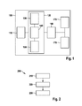
- Fig. 1 shows a schematic representation of a vehicle with a control device according to an embodiment of the present invention.
- the vehicle 100 has a vehicle camera 110, a control device 120 with a read-in device 130, a generation device 140 and a drive device 150, a headlight control device 160 and two headlights 170.
- the vehicle camera 110 is connected to the control device 120 via a communication interface, for example at least one signal line or the like.
- the headlight control unit 160 is connected to the control device 120 via a further communication interface, for example at least one signal line or the like.
- the control device 120 is connected between the vehicle camera 110 and the headlight controller 160.
- the headlights 170 are connected to the headlight control unit 160 via a further communication interface, for example at least one signal line or the like.
- the headlight controller 160 is connected between the control device 120 and the headlights 170. Even if it is in Fig. 1 is not shown, the drive device 160 may also be part of the control device 120 or the control device 120 may also be part of the headlight control unit 160.
- the vehicle camera 110 may have, for example, image processing electronics for suitable methods for image processing, image analysis, pattern recognition, object recognition and / or other signal processing electronics, etc. or be connected to the same.
- the vehicle camera 110 is in accordance with the in Fig. 1 1 to form a side impact warning signal, wherein the side impact warning signal represents a danger of side impact to the vehicle 100 by a foreign vehicle.
- Various logical values of the side impact warning signal may represent the presence or absence of a danger of side impact to the vehicle 100 by a foreign vehicle.
- the vehicle camera 110 is configured to output the side impact warning signal to the control device 120.
- the control device 120 has the read-in device 130, the generation device 140 and the drive device 150.
- the controller 120 may be configured to receive the side impact warning signal from the vehicle camera 110.
- the control device 120 is designed to effect a control of a light emission of the headlights 170 of the vehicle 100.
- the read-in device 130 is designed to read in the side-impact warning signal.
- the read-in device 130 may be configured to output the side-impact warning signal to the generator 140.
- the generation device 140 is configured to receive the side impact warning signal from the read-in device 130.
- the generator 140 is configured to generate a drive signal using the side impact warning signal and position information, the position information representing a position of the other vehicle relative to the vehicle.
- the generation device 140 or a device assigned to it can optionally determine the position information.
- the generating device 140 is designed to output the drive signal to the drive device 150.
- the driver 150 is configured to receive the drive signal from the generator 140.
- the drive device 150 is designed to base the light emission of the at least one headlight to control on the drive signal to illuminate the other vehicle by means of the at least one headlight.
- the driver 150 may be configured to generate control information that represents the drive and may be used to perform the control of the light emission.
- the driving device 150 is designed to output the control information to the headlight control unit 160.
- the headlamp controller 160 is configured to receive the control information from the controller 120 and the driver 150 of the controller 120, respectively.
- the headlamp controller 160 is also configured to generate a control signal for controlling the headlamps 170.
- the headlight controller 160 may use the control information for controlling the light emission of the headlights 170 when generating the control signal.
- the control signal may thus include the control information generated based on the drive signal in the control device 120.
- the headlight controller 160 is configured to output the control signal to the headlights 170.
- the headlights 170 may receive the control signal from the headlight controller 160.
- the control signal based on the drive signal in the control signal may cause the light emission of the headlights 170 to be controlled to warn of an impending side impact.
- FIG. 12 shows a flow chart of a method 200 for controlling a light emission of at least one headlight of a vehicle, according to an exemplary embodiment of the present invention.
- the method 200 includes a step of reading 210 a side impact warning signal.
- the side impact warning signal represents a danger of a side impact for the vehicle by a foreign vehicle.
- the method 200 also includes a step of generating 220 a drive signal using the side impact warning signal and position information.
- the position information represents a position of the foreign vehicle relative to the vehicle.
- the method 200 further includes a step 230 of driving the light emission of the at least one headlight based on the drive signal to illuminate the other vehicle by means of the at least one headlight.
- the method 200 may be used in conjunction with a device such as of the control device Fig. 1 , be carried out advantageously.
- the control device or the devices of the control device can Fig. 1 be configured to perform the steps of the method 200.
- Fig. 3 shows a schematic representation of a traffic situation with a risk of a side impact between a vehicle and a foreign vehicle.
- a road intersection with a traffic situation that can interpret a normal side impact warning function as a danger of side impact.
- Shown are a vehicle 100, a light cone 375, a first traffic light 380, a second traffic light 385 and a foreign vehicle 390.
- a first road and a second road intersect.
- the vehicle 100 is located on the first street in the intersection area near the first traffic light 380.
- the foreign vehicle 390 is located on the second street in the intersection area near the second traffic light 385.
- a directional arrow on the vehicle 100 and another directional arrow is displayed on the other vehicle 390.
- the directional arrows indicate that the directions of travel of the vehicle 100 and the other vehicle 390 intersect at the intersection.
- the vehicle 100 and the foreign vehicle 390 are moving toward each other approximately at right angles.
- the vehicle 100 is at risk of side impact by the foreign vehicle 390.
- the vehicle 100 may also be referred to as an ego vehicle.
- the light cone 375 is generated by two headlights of the vehicle 100. Specifically, the light cone 375 is generated by a light emission from two headlights of the vehicle 100. In this case, the light cone 375 may for example correspond to a low beam or be similar.
- the traffic light 380, near which the vehicle 100 is located, may hereby be green. Thus, driving through the intersection for the vehicle 100 is currently allowed.
- the second traffic light 385 near which the foreign vehicle 390 is located, may be red. Thus, driving through the intersection for the foreign vehicle 390 is currently not allowed. However, the foreign vehicle 390 is already partially between the second traffic lights 385 and an intersection of the two roads at the intersection. For example, a driver of the foreign vehicle 390 may have overlooked the red second traffic light 385. Thus, the foreign vehicle 390 is a vehicle with a possible accident risk.
- a conventional side impact warning system may now issue a warning to the driver of the vehicle 100 regarding a possible side impact.
- the vehicle 100 is the vehicle Fig. 1 may be due to the in Fig. 3 shown traffic situation, a method for controlling the light emission according to Fig. 2 executed and, for example, a side impact warning signal are read.
- Fig. 4 shows a schematic representation of a traffic situation with a risk of a side impact between a vehicle and a foreign vehicle.
- the representation in Fig. 4 corresponds to the representation from Fig. 3 with the exception that in Fig. 4 a modified light cone 475 of the vehicle 100 is shown.
- the vehicle 100 is the vehicle Fig. 1 .
- the modified light cone 475 is formed by applying the method Fig. 2
- the light emission of the vehicle 100 is controlled such that the modified light cone 475 is pivoted in the direction of the foreign vehicle 390 and the other vehicle 390 is at least partially illuminated by the light emission of the vehicle 100.
- the illumination of the other vehicle 390 or of the potential accident participant can represent a warning to the driver of the vehicle 100 that a side impact involving the other vehicle 390 is possible.
- Fig. 5 shows a schematic representation of a traffic situation with a risk of a side impact between a vehicle and a foreign vehicle.
- the representation in Fig. 5 corresponds to the representation from Fig. 3 with the exception that an additional light cone 575 is additionally shown.
- the vehicle 100 is the vehicle Fig. 1 ,
- the further light cone 575 may be generated by the light emission of a side impact warning light.
- the vehicle 100 is in addition to the vehicle Fig. 1 the side impact warning light on.
- the side impact warning light may include one or more warning lights.
- the further light cone 575 is formed by using the method Fig.
- the light emission of the vehicle 100 is controlled such that the further light cone 575 is directed toward the other vehicle 390 and the other vehicle 390 is at least partially illuminated by the light emission of the vehicle 100.
- the operation of the side impact warning function with illumination according to the method 200 according to the method of FIG Fig. 2 illustrated embodiment or using the control device 120 from Fig. 1
- the intelligent headlight controller directs the headlight cone 475 in response to an implementation of the method 200 or based on the drive signal generated in the controller 120 to illuminate the other vehicle ,
- this can be done using a lateral pivot control of the headlight 170.
- another emission characteristic of the headlight 170 can be changed by the activation of the light emission.
- the intelligent headlight controller will turn on the headlights 170 in response to an implementation of the method 200 or based on the drive signal generated in the controller 120 and direct the headlight cone 475 to the other vehicle 390 as a warning to its driver.
- an operation of the side impact warning function with lighting may be as follows. First, the side impact warning function detects a possible side impact. Then, a relative position of the target vehicle 390 with respect to the ego vehicle 100 is calculated. Then, the relative position of the target vehicle 390 together with a Signal indicating that a side impact warning is active transmitted to the headlight intelligent control unit. The Intelligent Headlight Control unit then adjusts the light cone to illuminate the vehicle with a potential accident risk.
- the light cone can be extended sideways. It can also be the headlights are turned on when they are still off.
- special side impact warning lights may be provided which may be mounted, for example, with side impact warning cameras. These side impact warning lights can be turned on to illuminate the approaching from the side other vehicle 390 in case of accident.
- the front headlights 170 of the vehicle 100 need not necessarily be changed in their light emission.
- this can be provided according to a further embodiment.
Landscapes
- Engineering & Computer Science (AREA)
- Mechanical Engineering (AREA)
- Lighting Device Outwards From Vehicle And Optical Signal (AREA)
Applications Claiming Priority (1)
| Application Number | Priority Date | Filing Date | Title |
|---|---|---|---|
| DE102011081360A DE102011081360A1 (de) | 2011-08-23 | 2011-08-23 | Verfahren zur Steuerung einer Lichtaussendung eines Scheinwerfers eines Fahrzeugs |
Publications (3)
| Publication Number | Publication Date |
|---|---|
| EP2562044A2 true EP2562044A2 (fr) | 2013-02-27 |
| EP2562044A3 EP2562044A3 (fr) | 2014-04-23 |
| EP2562044B1 EP2562044B1 (fr) | 2019-09-11 |
Family
ID=46466195
Family Applications (1)
| Application Number | Title | Priority Date | Filing Date |
|---|---|---|---|
| EP12174692.9A Active EP2562044B1 (fr) | 2011-08-23 | 2012-07-03 | Procédé de régulation de l'émission lumineuse d'un phare de véhicule |
Country Status (4)
| Country | Link |
|---|---|
| US (1) | US9545875B2 (fr) |
| EP (1) | EP2562044B1 (fr) |
| CN (1) | CN102951068B (fr) |
| DE (1) | DE102011081360A1 (fr) |
Families Citing this family (8)
| Publication number | Priority date | Publication date | Assignee | Title |
|---|---|---|---|---|
| DE102014214649A1 (de) * | 2014-07-25 | 2016-01-28 | Robert Bosch Gmbh | Verfahren und Vorrichtung zum Ausrichten eines Leuchtbereichs eines Scheinwerfers eines Fahrzeugs in Abhängigkeit eines Umfelds des Fahrzeugs |
| US20160144778A1 (en) | 2014-11-24 | 2016-05-26 | David M. Tucker | Enhanced communication system for vehicle hazard lights |
| KR101824982B1 (ko) | 2015-10-07 | 2018-02-02 | 엘지전자 주식회사 | 차량 및 그 제어방법 |
| DE102017206923B4 (de) * | 2017-04-25 | 2020-12-31 | Robert Bosch Gmbh | Steuerung einer gerichteten Lichtquelle |
| WO2020123672A1 (fr) | 2018-12-11 | 2020-06-18 | Ess-Help, Inc. | Amélioration de systèmes contre les dangers pour véhicule |
| US11590887B2 (en) | 2019-03-15 | 2023-02-28 | Ess-Help, Inc. | Control of high visibility vehicle light communication systems |
| US11518298B2 (en) | 2019-03-15 | 2022-12-06 | ESS-Help, lnc. | High visibility lighting for autonomous vehicles |
| CN113825949A (zh) | 2019-03-28 | 2021-12-21 | Ess协助股份有限公司 | 远程车辆危险和通信信标 |
Citations (1)
| Publication number | Priority date | Publication date | Assignee | Title |
|---|---|---|---|---|
| DE102008008884A1 (de) | 2008-02-13 | 2009-08-20 | Bayerische Motoren Werke Aktiengesellschaft | Fahrzeugleuchtensystem |
Family Cites Families (17)
| Publication number | Priority date | Publication date | Assignee | Title |
|---|---|---|---|---|
| DE10060734A1 (de) * | 2000-12-07 | 2002-06-13 | Opel Adam Ag | Kraftfahrzeug mit Mitteln zur Beleuchtung von Verkehrsschildern |
| GB0225839D0 (en) * | 2002-11-06 | 2002-12-11 | Ford Global Tech Inc | Interactive lighting system |
| US7541743B2 (en) * | 2002-12-13 | 2009-06-02 | Ford Global Technologies, Llc | Adaptive vehicle communication controlled lighting system |
| DE10336681B4 (de) * | 2003-08-09 | 2005-07-07 | Audi Ag | Kraftfahrzeug |
| US8027029B2 (en) * | 2007-11-07 | 2011-09-27 | Magna Electronics Inc. | Object detection and tracking system |
| JP4999652B2 (ja) * | 2007-11-19 | 2012-08-15 | アイシン精機株式会社 | 車両用ランプ制御システム |
| JP2009132230A (ja) | 2007-11-29 | 2009-06-18 | Omron Corp | 前照灯配光制御装置 |
| DE102008025947A1 (de) * | 2008-05-30 | 2009-12-03 | Hella Kgaa Hueck & Co. | Verfahren und Vorrichtung zum Steuern der Lichtabgabe eines Frontscheinwerfers eines Fahrzeugs |
| DE102008057375A1 (de) * | 2008-11-14 | 2010-05-20 | Daimler Ag | Verfahren zur Steuerung eines Fahrzeugsicherheitssystemes |
| US8935055B2 (en) * | 2009-01-23 | 2015-01-13 | Robert Bosch Gmbh | Method and apparatus for vehicle with adaptive lighting system |
| DE102009009472B4 (de) | 2009-02-19 | 2021-12-30 | Volkswagen Aktiengesellschaft | Verfahren zum Unterstützen eines Fahrers eines Fahrzeugs und Fahrerassistenzsystem für ein Fahrzeug |
| DE102009020910A1 (de) * | 2009-05-12 | 2010-11-18 | Volkswagen Ag | Scheinwerfersystem für ein Fahrzeug mit einem Bildgeber |
| DE102009035327A1 (de) * | 2009-07-30 | 2010-04-01 | Daimler Ag | Verfahren zur Steuerung eines Fahrlichts eines Fahrzeugs |
| JP5476914B2 (ja) * | 2009-10-13 | 2014-04-23 | 株式会社デンソー | 指向性制御照明装置 |
| DE102009051485A1 (de) * | 2009-10-30 | 2010-06-17 | Daimler Ag | Verfahren und Vorrichtung zur Steuerung eines Fahrlichts eines Fahrzeugs |
| JP5542501B2 (ja) | 2010-03-30 | 2014-07-09 | 株式会社小糸製作所 | 車両ランプシステム |
| DE102011081357A1 (de) | 2011-08-23 | 2013-02-28 | Robert Bosch Gmbh | Verfahren und Vorrichtung zur Ansteuerung eines Scheinwerfers eines Fahrzeugs |
-
2011
- 2011-08-23 DE DE102011081360A patent/DE102011081360A1/de not_active Ceased
-
2012
- 2012-07-03 EP EP12174692.9A patent/EP2562044B1/fr active Active
- 2012-08-16 US US13/587,712 patent/US9545875B2/en active Active
- 2012-08-22 CN CN201210301083.9A patent/CN102951068B/zh active Active
Patent Citations (1)
| Publication number | Priority date | Publication date | Assignee | Title |
|---|---|---|---|---|
| DE102008008884A1 (de) | 2008-02-13 | 2009-08-20 | Bayerische Motoren Werke Aktiengesellschaft | Fahrzeugleuchtensystem |
Also Published As
| Publication number | Publication date |
|---|---|
| CN102951068A (zh) | 2013-03-06 |
| CN102951068B (zh) | 2017-04-12 |
| US9545875B2 (en) | 2017-01-17 |
| EP2562044B1 (fr) | 2019-09-11 |
| EP2562044A3 (fr) | 2014-04-23 |
| US20130054087A1 (en) | 2013-02-28 |
| DE102011081360A1 (de) | 2013-02-28 |
Similar Documents
| Publication | Publication Date | Title |
|---|---|---|
| EP2562044B1 (fr) | Procédé de régulation de l'émission lumineuse d'un phare de véhicule | |
| DE102011081392B4 (de) | Verfahren zur Kalibrierung einer Lichtaussendung zumindest eines Scheinwerfers eines Fahrzeugs | |
| DE102011081382A1 (de) | Verfahren und Vorrichtung zum Ändern einer Lichtaussendung zumindest eines Scheinwerfers eines Fahrzeugs | |
| DE102014214607A1 (de) | ADB-Scheinwerfersystem und Verfahren zum Steuern von Strahlen unter Verwendung desselben | |
| DE102008058386A1 (de) | Verfahren und Anordnung zur Ansteuerung eines Fahrzeugscheinwerfers | |
| EP2748035B1 (fr) | Procédé et appareil de commande permettant d'adapter une intensité lumineuse d'au moins un projecteur d'un véhicule | |
| DE112017006833T5 (de) | Fahrzeugbeleuchtungssystem | |
| DE102013002212A1 (de) | Spurhalteassistenzsystem für ein Kraftfahrzeug | |
| DE102012200431B4 (de) | Verfahren zur Bestimmung eines Vorliegens einer Kreuzung in einem von einem Fahrzeug befahrenen Straßenverlauf | |
| DE102011081412B4 (de) | Verfahren und Vorrichtung zur Anpassung einer Lichtaussendung von zumindest einem Scheinwerfer eines Fahrzeugs | |
| DE102014018995A1 (de) | Verfahren zum Betrieb eines Scheinwerfers sowie Kraftfahrzeugscheinwerfer | |
| DE102018129849A1 (de) | Scheinwerfersteuerung basierend auf Nachrichten- und Sensordaten | |
| DE102018206042A1 (de) | Verfahren zur Kommunikation eines Kraftfahrzeugs mit einem Verkehrsteilnehmer sowie Kraftfahrzeug zur Durchführung des Verfahrens | |
| DE102007054048A1 (de) | Verfahren und Vorrichtung für eine Fahrlichtsteuerung eines Fahrzeugs | |
| DE102010038961A1 (de) | Verfahren und Vorrichtung zum Bestimmen einer Empfehlung für eine Strahlungscharakteristik zumindest eines Schweinwerfers eines Fahrzeugs | |
| DE102015200132A1 (de) | Verfahren zum Erzeugen einer Lichtverteilung für ein erstes Fahrzeug | |
| DE102014009254A1 (de) | Verfahren zum Steuern einer Lichtverteilung eines Scheinwerfers eines Fahrzeugs | |
| DE102011115670A1 (de) | Verfahren zum Betreiben eines Fahrerassistenzsystems und Fahrerassistenzsystem | |
| WO2018103875A1 (fr) | Procédé de commande de distribution d'une lumière avant d'un véhicule | |
| EP2131308B1 (fr) | Procédé et dispositif de classification d'un objet détecté dans au moins une image d'une zone à l'avant d'un véhicule | |
| WO2018019413A1 (fr) | Dispositif de commande pour un phare et procédé permettant de faire fonctionner un phare | |
| DE102011120223A1 (de) | Anordnung und Verfahren zur Verhinderungvon Wildunfällen | |
| DE102016004289A1 (de) | Verfahren und Vorrichtung zur Steuerung einer Fahrzeugbeleuchtung und Fahrzeug mit einer solchen Vorrichtung | |
| WO2016173762A1 (fr) | Procédé de commande d'une intensité lumineuse de feux stop | |
| DE102013001286A1 (de) | Scheinwerfersystem für ein Kraftfahrzeug |
Legal Events
| Date | Code | Title | Description |
|---|---|---|---|
| PUAI | Public reference made under article 153(3) epc to a published international application that has entered the european phase |
Free format text: ORIGINAL CODE: 0009012 |
|
| AK | Designated contracting states |
Kind code of ref document: A2 Designated state(s): AL AT BE BG CH CY CZ DE DK EE ES FI FR GB GR HR HU IE IS IT LI LT LU LV MC MK MT NL NO PL PT RO RS SE SI SK SM TR |
|
| AX | Request for extension of the european patent |
Extension state: BA ME |
|
| PUAL | Search report despatched |
Free format text: ORIGINAL CODE: 0009013 |
|
| AK | Designated contracting states |
Kind code of ref document: A3 Designated state(s): AL AT BE BG CH CY CZ DE DK EE ES FI FR GB GR HR HU IE IS IT LI LT LU LV MC MK MT NL NO PL PT RO RS SE SI SK SM TR |
|
| AX | Request for extension of the european patent |
Extension state: BA ME |
|
| RIC1 | Information provided on ipc code assigned before grant |
Ipc: B60Q 1/52 20060101ALI20140314BHEP Ipc: B60Q 1/18 20060101AFI20140314BHEP Ipc: B60Q 1/08 20060101ALI20140314BHEP |
|
| 17P | Request for examination filed |
Effective date: 20141023 |
|
| RBV | Designated contracting states (corrected) |
Designated state(s): AL AT BE BG CH CY CZ DE DK EE ES FI FR GB GR HR HU IE IS IT LI LT LU LV MC MK MT NL NO PL PT RO RS SE SI SK SM TR |
|
| GRAP | Despatch of communication of intention to grant a patent |
Free format text: ORIGINAL CODE: EPIDOSNIGR1 |
|
| STAA | Information on the status of an ep patent application or granted ep patent |
Free format text: STATUS: GRANT OF PATENT IS INTENDED |
|
| INTG | Intention to grant announced |
Effective date: 20190318 |
|
| GRAS | Grant fee paid |
Free format text: ORIGINAL CODE: EPIDOSNIGR3 |
|
| GRAA | (expected) grant |
Free format text: ORIGINAL CODE: 0009210 |
|
| STAA | Information on the status of an ep patent application or granted ep patent |
Free format text: STATUS: THE PATENT HAS BEEN GRANTED |
|
| AK | Designated contracting states |
Kind code of ref document: B1 Designated state(s): AL AT BE BG CH CY CZ DE DK EE ES FI FR GB GR HR HU IE IS IT LI LT LU LV MC MK MT NL NO PL PT RO RS SE SI SK SM TR |
|
| REG | Reference to a national code |
Ref country code: GB Ref legal event code: FG4D Free format text: NOT ENGLISH |
|
| REG | Reference to a national code |
Ref country code: CH Ref legal event code: EP |
|
| REG | Reference to a national code |
Ref country code: AT Ref legal event code: REF Ref document number: 1178019 Country of ref document: AT Kind code of ref document: T Effective date: 20190915 |
|
| REG | Reference to a national code |
Ref country code: DE Ref legal event code: R096 Ref document number: 502012015273 Country of ref document: DE Ref country code: IE Ref legal event code: FG4D Free format text: LANGUAGE OF EP DOCUMENT: GERMAN |
|
| REG | Reference to a national code |
Ref country code: NL Ref legal event code: MP Effective date: 20190911 |
|
| REG | Reference to a national code |
Ref country code: LT Ref legal event code: MG4D |
|
| PG25 | Lapsed in a contracting state [announced via postgrant information from national office to epo] |
Ref country code: FI Free format text: LAPSE BECAUSE OF FAILURE TO SUBMIT A TRANSLATION OF THE DESCRIPTION OR TO PAY THE FEE WITHIN THE PRESCRIBED TIME-LIMIT Effective date: 20190911 Ref country code: BG Free format text: LAPSE BECAUSE OF FAILURE TO SUBMIT A TRANSLATION OF THE DESCRIPTION OR TO PAY THE FEE WITHIN THE PRESCRIBED TIME-LIMIT Effective date: 20191211 Ref country code: SE Free format text: LAPSE BECAUSE OF FAILURE TO SUBMIT A TRANSLATION OF THE DESCRIPTION OR TO PAY THE FEE WITHIN THE PRESCRIBED TIME-LIMIT Effective date: 20190911 Ref country code: NO Free format text: LAPSE BECAUSE OF FAILURE TO SUBMIT A TRANSLATION OF THE DESCRIPTION OR TO PAY THE FEE WITHIN THE PRESCRIBED TIME-LIMIT Effective date: 20191211 Ref country code: HR Free format text: LAPSE BECAUSE OF FAILURE TO SUBMIT A TRANSLATION OF THE DESCRIPTION OR TO PAY THE FEE WITHIN THE PRESCRIBED TIME-LIMIT Effective date: 20190911 Ref country code: LT Free format text: LAPSE BECAUSE OF FAILURE TO SUBMIT A TRANSLATION OF THE DESCRIPTION OR TO PAY THE FEE WITHIN THE PRESCRIBED TIME-LIMIT Effective date: 20190911 |
|
| PG25 | Lapsed in a contracting state [announced via postgrant information from national office to epo] |
Ref country code: AL Free format text: LAPSE BECAUSE OF FAILURE TO SUBMIT A TRANSLATION OF THE DESCRIPTION OR TO PAY THE FEE WITHIN THE PRESCRIBED TIME-LIMIT Effective date: 20190911 Ref country code: GR Free format text: LAPSE BECAUSE OF FAILURE TO SUBMIT A TRANSLATION OF THE DESCRIPTION OR TO PAY THE FEE WITHIN THE PRESCRIBED TIME-LIMIT Effective date: 20191212 Ref country code: LV Free format text: LAPSE BECAUSE OF FAILURE TO SUBMIT A TRANSLATION OF THE DESCRIPTION OR TO PAY THE FEE WITHIN THE PRESCRIBED TIME-LIMIT Effective date: 20190911 Ref country code: ES Free format text: LAPSE BECAUSE OF FAILURE TO SUBMIT A TRANSLATION OF THE DESCRIPTION OR TO PAY THE FEE WITHIN THE PRESCRIBED TIME-LIMIT Effective date: 20190911 Ref country code: RS Free format text: LAPSE BECAUSE OF FAILURE TO SUBMIT A TRANSLATION OF THE DESCRIPTION OR TO PAY THE FEE WITHIN THE PRESCRIBED TIME-LIMIT Effective date: 20190911 |
|
| RAP2 | Party data changed (patent owner data changed or rights of a patent transferred) |
Owner name: ROBERT BOSCH GMBH |
|
| PG25 | Lapsed in a contracting state [announced via postgrant information from national office to epo] |
Ref country code: PL Free format text: LAPSE BECAUSE OF FAILURE TO SUBMIT A TRANSLATION OF THE DESCRIPTION OR TO PAY THE FEE WITHIN THE PRESCRIBED TIME-LIMIT Effective date: 20190911 Ref country code: PT Free format text: LAPSE BECAUSE OF FAILURE TO SUBMIT A TRANSLATION OF THE DESCRIPTION OR TO PAY THE FEE WITHIN THE PRESCRIBED TIME-LIMIT Effective date: 20200113 Ref country code: NL Free format text: LAPSE BECAUSE OF FAILURE TO SUBMIT A TRANSLATION OF THE DESCRIPTION OR TO PAY THE FEE WITHIN THE PRESCRIBED TIME-LIMIT Effective date: 20190911 Ref country code: RO Free format text: LAPSE BECAUSE OF FAILURE TO SUBMIT A TRANSLATION OF THE DESCRIPTION OR TO PAY THE FEE WITHIN THE PRESCRIBED TIME-LIMIT Effective date: 20190911 Ref country code: EE Free format text: LAPSE BECAUSE OF FAILURE TO SUBMIT A TRANSLATION OF THE DESCRIPTION OR TO PAY THE FEE WITHIN THE PRESCRIBED TIME-LIMIT Effective date: 20190911 Ref country code: IT Free format text: LAPSE BECAUSE OF FAILURE TO SUBMIT A TRANSLATION OF THE DESCRIPTION OR TO PAY THE FEE WITHIN THE PRESCRIBED TIME-LIMIT Effective date: 20190911 |
|
| PG25 | Lapsed in a contracting state [announced via postgrant information from national office to epo] |
Ref country code: SM Free format text: LAPSE BECAUSE OF FAILURE TO SUBMIT A TRANSLATION OF THE DESCRIPTION OR TO PAY THE FEE WITHIN THE PRESCRIBED TIME-LIMIT Effective date: 20190911 Ref country code: CZ Free format text: LAPSE BECAUSE OF FAILURE TO SUBMIT A TRANSLATION OF THE DESCRIPTION OR TO PAY THE FEE WITHIN THE PRESCRIBED TIME-LIMIT Effective date: 20190911 Ref country code: IS Free format text: LAPSE BECAUSE OF FAILURE TO SUBMIT A TRANSLATION OF THE DESCRIPTION OR TO PAY THE FEE WITHIN THE PRESCRIBED TIME-LIMIT Effective date: 20200224 Ref country code: SK Free format text: LAPSE BECAUSE OF FAILURE TO SUBMIT A TRANSLATION OF THE DESCRIPTION OR TO PAY THE FEE WITHIN THE PRESCRIBED TIME-LIMIT Effective date: 20190911 |
|
| REG | Reference to a national code |
Ref country code: DE Ref legal event code: R097 Ref document number: 502012015273 Country of ref document: DE |
|
| PLBE | No opposition filed within time limit |
Free format text: ORIGINAL CODE: 0009261 |
|
| STAA | Information on the status of an ep patent application or granted ep patent |
Free format text: STATUS: NO OPPOSITION FILED WITHIN TIME LIMIT |
|
| PG2D | Information on lapse in contracting state deleted |
Ref country code: IS |
|
| PG25 | Lapsed in a contracting state [announced via postgrant information from national office to epo] |
Ref country code: DK Free format text: LAPSE BECAUSE OF FAILURE TO SUBMIT A TRANSLATION OF THE DESCRIPTION OR TO PAY THE FEE WITHIN THE PRESCRIBED TIME-LIMIT Effective date: 20190911 Ref country code: IS Free format text: LAPSE BECAUSE OF FAILURE TO SUBMIT A TRANSLATION OF THE DESCRIPTION OR TO PAY THE FEE WITHIN THE PRESCRIBED TIME-LIMIT Effective date: 20200112 |
|
| 26N | No opposition filed |
Effective date: 20200615 |
|
| PG25 | Lapsed in a contracting state [announced via postgrant information from national office to epo] |
Ref country code: SI Free format text: LAPSE BECAUSE OF FAILURE TO SUBMIT A TRANSLATION OF THE DESCRIPTION OR TO PAY THE FEE WITHIN THE PRESCRIBED TIME-LIMIT Effective date: 20190911 |
|
| PG25 | Lapsed in a contracting state [announced via postgrant information from national office to epo] |
Ref country code: MC Free format text: LAPSE BECAUSE OF FAILURE TO SUBMIT A TRANSLATION OF THE DESCRIPTION OR TO PAY THE FEE WITHIN THE PRESCRIBED TIME-LIMIT Effective date: 20190911 |
|
| REG | Reference to a national code |
Ref country code: CH Ref legal event code: PL |
|
| REG | Reference to a national code |
Ref country code: BE Ref legal event code: MM Effective date: 20200731 |
|
| PG25 | Lapsed in a contracting state [announced via postgrant information from national office to epo] |
Ref country code: LU Free format text: LAPSE BECAUSE OF NON-PAYMENT OF DUE FEES Effective date: 20200703 Ref country code: IE Free format text: LAPSE BECAUSE OF NON-PAYMENT OF DUE FEES Effective date: 20200703 Ref country code: LI Free format text: LAPSE BECAUSE OF NON-PAYMENT OF DUE FEES Effective date: 20200731 Ref country code: CH Free format text: LAPSE BECAUSE OF NON-PAYMENT OF DUE FEES Effective date: 20200731 |
|
| PG25 | Lapsed in a contracting state [announced via postgrant information from national office to epo] |
Ref country code: BE Free format text: LAPSE BECAUSE OF NON-PAYMENT OF DUE FEES Effective date: 20200731 |
|
| REG | Reference to a national code |
Ref country code: AT Ref legal event code: MM01 Ref document number: 1178019 Country of ref document: AT Kind code of ref document: T Effective date: 20200703 |
|
| PG25 | Lapsed in a contracting state [announced via postgrant information from national office to epo] |
Ref country code: AT Free format text: LAPSE BECAUSE OF NON-PAYMENT OF DUE FEES Effective date: 20200703 |
|
| PG25 | Lapsed in a contracting state [announced via postgrant information from national office to epo] |
Ref country code: TR Free format text: LAPSE BECAUSE OF FAILURE TO SUBMIT A TRANSLATION OF THE DESCRIPTION OR TO PAY THE FEE WITHIN THE PRESCRIBED TIME-LIMIT Effective date: 20190911 Ref country code: MT Free format text: LAPSE BECAUSE OF FAILURE TO SUBMIT A TRANSLATION OF THE DESCRIPTION OR TO PAY THE FEE WITHIN THE PRESCRIBED TIME-LIMIT Effective date: 20190911 Ref country code: CY Free format text: LAPSE BECAUSE OF FAILURE TO SUBMIT A TRANSLATION OF THE DESCRIPTION OR TO PAY THE FEE WITHIN THE PRESCRIBED TIME-LIMIT Effective date: 20190911 |
|
| PG25 | Lapsed in a contracting state [announced via postgrant information from national office to epo] |
Ref country code: MK Free format text: LAPSE BECAUSE OF FAILURE TO SUBMIT A TRANSLATION OF THE DESCRIPTION OR TO PAY THE FEE WITHIN THE PRESCRIBED TIME-LIMIT Effective date: 20190911 |
|
| PGFP | Annual fee paid to national office [announced via postgrant information from national office to epo] |
Ref country code: GB Payment date: 20220725 Year of fee payment: 11 |
|
| PGFP | Annual fee paid to national office [announced via postgrant information from national office to epo] |
Ref country code: FR Payment date: 20220725 Year of fee payment: 11 |
|
| PGFP | Annual fee paid to national office [announced via postgrant information from national office to epo] |
Ref country code: DE Payment date: 20230922 Year of fee payment: 12 |
|
| GBPC | Gb: european patent ceased through non-payment of renewal fee |
Effective date: 20230703 |
|
| PG25 | Lapsed in a contracting state [announced via postgrant information from national office to epo] |
Ref country code: GB Free format text: LAPSE BECAUSE OF NON-PAYMENT OF DUE FEES Effective date: 20230703 |