EP2561425B1 - Mensch-maschine-schnittstelle mit verstärktem gehäuse - Google Patents
Mensch-maschine-schnittstelle mit verstärktem gehäuse Download PDFInfo
- Publication number
- EP2561425B1 EP2561425B1 EP11721566.5A EP11721566A EP2561425B1 EP 2561425 B1 EP2561425 B1 EP 2561425B1 EP 11721566 A EP11721566 A EP 11721566A EP 2561425 B1 EP2561425 B1 EP 2561425B1
- Authority
- EP
- European Patent Office
- Prior art keywords
- edge
- housing
- touch
- casing
- detection means
- Prior art date
- Legal status (The legal status is an assumption and is not a legal conclusion. Google has not performed a legal analysis and makes no representation as to the accuracy of the status listed.)
- Active
Links
Images

Classifications
-
- G—PHYSICS
- G06—COMPUTING OR CALCULATING; COUNTING
- G06F—ELECTRIC DIGITAL DATA PROCESSING
- G06F1/00—Details not covered by groups G06F3/00 - G06F13/00 and G06F21/00
- G06F1/16—Constructional details or arrangements
- G06F1/1601—Constructional details related to the housing of computer displays, e.g. of CRT monitors, of flat displays
-
- G—PHYSICS
- G06—COMPUTING OR CALCULATING; COUNTING
- G06F—ELECTRIC DIGITAL DATA PROCESSING
- G06F1/00—Details not covered by groups G06F3/00 - G06F13/00 and G06F21/00
- G06F1/16—Constructional details or arrangements
- G06F1/1613—Constructional details or arrangements for portable computers
- G06F1/1633—Constructional details or arrangements of portable computers not specific to the type of enclosures covered by groups G06F1/1615 - G06F1/1626
- G06F1/1637—Details related to the display arrangement, including those related to the mounting of the display in the housing
- G06F1/1643—Details related to the display arrangement, including those related to the mounting of the display in the housing the display being associated to a digitizer, e.g. laptops that can be used as penpads
-
- G—PHYSICS
- G06—COMPUTING OR CALCULATING; COUNTING
- G06F—ELECTRIC DIGITAL DATA PROCESSING
- G06F3/00—Input arrangements for transferring data to be processed into a form capable of being handled by the computer; Output arrangements for transferring data from processing unit to output unit, e.g. interface arrangements
- G06F3/01—Input arrangements or combined input and output arrangements for interaction between user and computer
- G06F3/03—Arrangements for converting the position or the displacement of a member into a coded form
- G06F3/033—Pointing devices displaced or positioned by the user, e.g. mice, trackballs, pens or joysticks; Accessories therefor
- G06F3/0354—Pointing devices displaced or positioned by the user, e.g. mice, trackballs, pens or joysticks; Accessories therefor with detection of 2D relative movements between the device, or an operating part thereof, and a plane or surface, e.g. 2D mice, trackballs, pens or pucks
- G06F3/03547—Touch pads, in which fingers can move on a surface
-
- G—PHYSICS
- G06—COMPUTING OR CALCULATING; COUNTING
- G06F—ELECTRIC DIGITAL DATA PROCESSING
- G06F3/00—Input arrangements for transferring data to be processed into a form capable of being handled by the computer; Output arrangements for transferring data from processing unit to output unit, e.g. interface arrangements
- G06F3/01—Input arrangements or combined input and output arrangements for interaction between user and computer
- G06F3/03—Arrangements for converting the position or the displacement of a member into a coded form
- G06F3/041—Digitisers, e.g. for touch screens or touch pads, characterised by the transducing means
Definitions
- the technical field of the present invention is that of tactile detection devices embedded in a human-machine interface. These tactile detection devices are used today in many sectors such as home automation, computer equipment and generally for all control systems of equipment.
- the invention relates more particularly to the application of such devices to the motor vehicle.
- these devices are commonly called human-machine interfaces as a display device and control of vehicle equipment. This type of human-machine interface is found in the cabin of the vehicle to control the navigation system, the audio or multimedia system or the air conditioning system.
- a screen is installed in a housing, the latter having an opening.
- the screen has an upper face on which is placed a sensor to the right of the opening.
- the opening is bordered by a periphery of the housing, said periphery covering the sensor substantially by forming a shoulder at the intersection of the sensor and the periphery.
- the object of the present invention is therefore to solve the disadvantages described above mainly by reinforcing the frame or housing so as to avoid thermal expansion gaps that could cause games, days or cracks unsightly from the point of view of the user of the man-machine interface.
- a first advantage of the invention lies in the possibility of implementing a human-machine interface that has a smooth and pleasant to the touch using economical technical means.
- Another advantage lies in the possibility of guaranteeing perfect mechanical resistance to the thermal and mechanical stresses of the human-machine interface by means of a simple means to implement.
- the figure 1 represents a schematic front view of a man-machine interface 1 for a motor vehicle.
- Such an interface 1 is fixed near a user, for example at a central console of the vehicle or at the dashboard, to control functions or equipment of the vehicle. These are for example the installation of ventilation, heating and / or air conditioning, an audio system, a telephony system, a multimedia system or a navigation system.
- the human-machine interface 1 comprises a box 3 of rectangular shape inside which is installed a tactile detection means 2.
- An opening 5 is made in the housing so as to make accessible by the user the tactile detection means 2.
- This opening 5 is delimited by an edge 4 of the housing 3, this edge 4 extending peripherally around the opening 5.
- a leveling pad 13 is interposed between the edge 4 of the housing and a peripheral wafer 15. of the tactile detection means 2.
- the housing 3 comprises an internal recess inside which are installed complementary elements to the interface.
- a display device (not shown) is installed in the recess made in the housing 3.
- the technology used by the display device is for example a backlit screen, an LCD screen, a screen plasma and in general any single-function screen such as an air conditioning control panel or multifunction, that is to say, displaying a multiplicity of information such as navigation, audio system, thermal management of the cabin of the vehicle for example.
- the tactile detection means 2 consists of a resistive sensor or a capacitive sensor, one or the other being transparent.
- a resistive sensor the latter consists of a main plate and a secondary plate. These two plates are glass, the secondary plate being thinner than the main plate.
- the secondary plate has the function of being deformed under a pressing force exerted by the finger of the user while the main plate is less deformable, its thickness is such that it does not flex under the effect of pressure exerted by the finger of a user.
- the sensor is thus able to detect the position of the user's finger thanks to a network of conductors placed between the main plate and the secondary plate, in a horizontal and vertical arrangement, for example.
- the tactile detection means 2 is electrically connected to an electronic card by means of a multi-conductor hose, the electronic card providing interpretation of the detection performed by the tactile detection means 2.
- the housing 3 comprises a reinforcement means 6 whose variants will be better detailed below.
- the inner dotted line illustrates an inner edge referenced 18 of the reinforcing means
- the dashed line following outwardly of the interface illustrates an inner wall 19 of the housing 3
- the last dotted line shows a first part of the means reinforcement 6, and more particularly an outer edge referenced 20 of the reinforcement means 6.
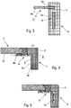
- the figure 2 shows a partial section of the human-machine interface according to the invention according to a section XX presented on the figure 1 .
- the tactile detection means 2 has an upper face 11 facing the user U and a lower face 16 facing the internal recess 17 formed in the housing 3.
- the latter has an inverted section "L" and the means reinforcement 6 is integrated in the plastic material which forms the casing 3.
- the reinforcement means 6 is molded by the casing 3 according to a method in which the reinforcement means is installed in a mold and in which the material is injected.
- plastic housing in the liquid state to engage a first portion 6a of the reinforcing means 6.
- This first portion 6a is an outer edge which may comprise holes (not shown) allowing the plastic material to pass through the reinforcement means and thus to increase the mechanical connection between the reinforcement means 6 and the housing 3.
- the material of the reinforcing means 6 is chosen from materials having a coefficient of expansion identical to plus or minus 33% of the material constituting the tactile detection means 2.
- the coefficient of Expansion of the glass is equal to 9x10 -6 for 1 / K which allows a choice of material for the reinforcing means whose expansion coefficient is at most 12x10 -6 for 1 / K. This is the case of steel and that is why it is easy to strengthen the housing 3 by drowning a metal plate, for example steel.
- the edge 4 of the housing defines the opening 5 where is placed the tactile detection means 2, otherwise called touch sensor or touch screen.
- a wafer 21 borders the opening 5 and this wafer ends with a contact on the reinforcement means 6.
- the reinforcing means takes the form of a flat metal plate with a thickness between 0.20 and 0.50 mm.
- this metal plate comprises a second portion 6b which opens into the internal volume delimited by the housing or in other words in the recess 17. This second part 6b is extends at the level of the opening 5 and serves as a support for the tactile detection means 2.
- the metal plate, forming reinforcing means 6 has a hole 7 delimited or bordered by the second part 6b of the reinforcement means.
- the reinforcing means is unique for the human-machine interface according to the invention and takes a generally rectangular shape with the hole 7 at its center. The latter allows the light rays of the lighting device to pass through the tactile detection means 2 so as to make the information displayed by the display device visible to the user.
- the tactile detection means 2 comprises a border 30 terminated by the peripheral wafer 15.
- This border 30 is a zone for fastening or securing the tactile detection means 2 to the reinforcement means 6. More particularly, the fastening intervenes between the lower facade 16 the tactile detection means 2, at the right of the border 30, and an upper face 8 facing a user of the reinforcing means 6.
- the fixing is effected by means of glue point or an adhesive strip 22 placed between the lower face 16 of the tactile detection means 2 and the upper face 8 of the reinforcement means 6.
- the reinforcement means 6 has a lower face 9 which is in turn facing the recess 17 of the housing 3.
- the upper face 11 of the tactile detection means 2 that is to say the one facing the user, is aligned in the same plane C that a facade strip 12 that has the edge 4 of the housing 3 and which also faces the user. This ensures that the visible side by the user of the man-machine interface is perfectly smooth to the touch.
- first portion 6a and the second portion 6b of the reinforcing means 6 extend in the same plane parallel to the plane C.
- the human-machine interface comprises the leveling pad 13, peripheral to the touch screen or tactile detection means 2, to fill the space delimited by the edge 21 of the edge 4, the upper face 8 of the means of reinforcement 6 and the peripheral edge 15 of the tactile detection means 2. This ensures a smooth continuity of the control surface of the tactile detection means 2 with the edge 4 of the housing 3.
- a material which can be cast or injected at low pressure and at low temperature is chosen, such as an elastomer, such as an EPDM material (Ethylene Propylene Diene Monomer), a TPE (thermoplastic elastomer such as a SEBS material (Styrene-ethylene-butylene-styrene), SBS (styrene-butadiene-styrene) or TPU (thermoplastic polyurethane)) or a silicone elastomer. Once cured, these materials stiffen, providing a smooth feel.
- an elastomer such as an EPDM material (Ethylene Propylene Diene Monomer)
- TPE thermoplastic elastomer such as a SEBS material (Styrene-ethylene-butylene-styrene), SBS (styrene-butadiene-styrene) or TPU (thermoplastic polyurethane)
- a silicone elastomer such
- the figure 3 shows a variant of the invention which uses a multiplicity of reinforcing means 6.
- multiplicity is meant at least two metal plates orthogonally oriented relative to each other but it can also be a multiplicity of metal plates and placed in each side of the rectangle formed by the housing 3 (according to the figure 1 ).
- a first reinforcing means 6 is integrally embedded in the plastic material constituting the housing 3 and a second reinforcement means 6 is installed in the upper part of the edge 4, a first part 6a of the reinforcement means 6 being overmolded or embedded in the constituent material of the housing 3 while a second portion 6b protrudes from the inner wall 19 of the housing towards the recess 17.
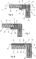
- the figure 4 shows an alternative embodiment of the reinforcement means 6.
- the metal plate forming a reinforcing means 6 is shaped such that its first portion 6a is angularly oriented relative to its second portion 6b while not forming only one room.
- the first portion 6a and the second portion 6b respectively extend in a first plane A and a second plane B which form an angle of 90 °.
- said planes A and B can take an angle of between 75 ° and 105 °, the important thing being that the second part 6b of the reinforcing means is parallel to the lower face 16 of the detection means 2 and that the first part 6a of the reinforcement means 6 is completely contained or embedded in the edge 4 of the housing 3.
- the figure 4 illustrates another difference with the embodiment of the figure 2 .
- the first portion 6a is embedded in the edge 4 at the inner wall 19 so that the lower face 9 of the reinforcing means 6 is flush with the inner wall 19 once the reinforcing means is secured to the edge 4 3.
- the lower face 9 at the first portion 6a is visible inside the housing 3.
- the figure 5 illustrates a variant close to that illustrated in figure 4 .
- the difference lies in the fact that the first part 6a of the reinforcing means 6 is integrally embedded in the plastic material constituting the edge 4 of the housing 3. It will be particularly noted that the first portion 6a is substantially embedded in the center of the thickness of the edge 4 forming the housing 3.
- the rest of the realization of the figure 5 is identical to the embodiment of the figure 4 .
- the figure 6 is a variant where the leveling pad further ensures the function of securing the tactile detection means 2 on the reinforcement means 6.
- the first part 6a of the reinforcing means 6 is integrally embedded in the plastic material constituting the edge 4 of the housing 3 while the second portion 6b protrudes or opens from the inner wall 19 of the housing towards the recess 17, substantially at the opening 5.
- the leveling pad 13 comprises adhesive properties so as to ensure the bonding between the lower face 16 of the tactile detection means 2 and the upper face 8 of the second part 6b of the reinforcement means 6. To do this, the leveling pad is inserted between these two walls and ensures the bonding of the latter.
- the leveling lining 13 therefore fills the space delimited by the edge 21 of the edge 4, the upper face 8 of the reinforcement means 6, the peripheral edge 15 of the tactile detection means 2 and the lower face 16 of the same means, where it performs its function of collage.
- the upper face 11, an upper face 31 of the leveling lining and the front strip 12 of the edge 4 are contained in the same plane C so as to guarantee the smooth and uniform character of the human machine interface 1.
- the figure 7 illustrates a variant complementary to that illustrated in figure 6 .
- the invention proposes to fold the second portion 6b of the reinforcing means 6 so as to form a cradle containing the leveling pad before solidification.
- the second part 6b thus has at its free end a fold 23 substantially perpendicular to the second plane B in which the second portion extends 6b and oriented towards the upper face 11 of the tactile detection means 2.
- the inner portion 18 reinforcement means 6 is thus in contact on the lower face 16 of the tactile detection means 2.
- a film 24 is disposed on the upper face 11 of the tactile detection means 2 so as to cover the opening 5, the leveling pad 13 and the edge 4 of the box 3
- This film extends over the entire surface of the human-machine interface, it is therefore clear that the dimensions of the film 24 and the dimensions of the interface 1 are similar, or even identical. This film thus forms a surface that is completely smooth and uniform to the touch for the user.
- the film 24 is a transparent film that may have a single property or a combination of properties.
- a first property is related to the decorative character that this film takes. Indeed, it is then easy to define a particular form visible by the user.
- the film 24 may also include anti-scratch properties so as to avoid the appearance of any scratches on the surface of the man-machine interface.
- the film can also present a anti-reflective and diffusing property, the latter giving a matte appearance to the man-machine interface and avoiding annoying mirror effects for the user.
- the anti-reflective property prevents the incident light from coming out of the surface. This is a thin film treatment.
- the film can also include diffusion properties, obtained by a light lubrication that bursts the incident light by returning it in all directions.
- the film 24 may have polarizing properties, that is to say able to block the light reflected by the glass plates of the tactile detection means in a given direction.
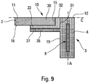
- the edge 4 of the housing 3 has the front panel 12 constituted by the wall of the edge 4 facing the user.
- the first part 6a is embedded or overmolded in the edge 4 of the housing 3 and the second part 6b of the reinforcement means 6 protrudes or protrudes from the edge 4 at the opening 5.
- the attachment mode of the tactile detection means is different from the variants described above.
- the tactile detection means 2 is fixed on the lower face 9 of the reinforcement means 6.
- a bead or points of glue 22 make the mechanical link between the upper face 11 of the tactile detection means and the lower face 9 of the metal plate forming a reinforcement means of the housing but also support of the tactile detection means.
- the glue points can be replaced or supplemented with an adhesive tape. This arrangement makes it possible to obtain a tactile detection means assembled in the man-machine interface in "suspended" mode.
- a filling element 25 the objective of which is to define, together with the upper face 8 of the reinforcement means 6, a flat and smooth surface, is added at the level of the opening 5 bearing against the upper face 11 of the detection means. touch.
- the filling element 25 is a transparent and flexible film made from a polycarbonate or polyethylene terephthalate (PET) strip and its thickness is equal to the sum of the thickness of the reinforcement means 6, particularly at its second portion 6b with the thickness of the glue 22.
- PET polyethylene terephthalate
- a film 24 is deposited on the filling element 25, on the upper face 8 of the reinforcing means 6, at its second part 6b, and finally on the facade band 12.
- the reinforcing means provides a primary function, which is to strengthen the mechanical strength of the edge of the housing, and a secondary function which is to support the tactile detection means.
- these functions are decoupled.
- the reinforcing means does not support the tactile detection means, this function being devolved on the housing 3.
- the housing 3 comprises a shoulder 26 which receives the tactile detection means 2 and more particularly its border 30.
- This shoulder 23 originates on the inner wall 19 in the direction of the internal recess 17.
- the direction of extension of the shoulder 26 is therefore substantially perpendicular to the extension direction A of the reinforcement means 6 embedded integrally in the edge 4 of the housing 3.
- the shoulder 26 and the wafer 21 of the opening 5 delimit a receiving zone 10 of the border 20 of the tactile detection means 2.
- a band of glue 22 is interposed between the lower face 16 of the control means.
- the housing receives and maintains the tactile detection means while being reinforced by a metal plate embedded in the edge of the housing.
- the upper face 11 of the tactile detection means 2 that is to say the one facing the user, an upper edge 32 of the glue strip 22 and the front strip 12 of the edge 4 are contained in a same plane C so as to ensure the smooth and uniform character of the man-machine interface 1. This ensures that the face visible by the user of the man-machine interface is perfectly smooth to the touch.
Landscapes
- Engineering & Computer Science (AREA)
- Theoretical Computer Science (AREA)
- General Engineering & Computer Science (AREA)
- Human Computer Interaction (AREA)
- Physics & Mathematics (AREA)
- General Physics & Mathematics (AREA)
- Computer Hardware Design (AREA)
- Casings For Electric Apparatus (AREA)
- User Interface Of Digital Computer (AREA)
- Position Input By Displaying (AREA)
- Switches That Are Operated By Magnetic Or Electric Fields (AREA)
- Manipulator (AREA)
- Ultra Sonic Daignosis Equipment (AREA)
Claims (4)
- Mensch-Maschine-Schnittstelle (1), die eine taktile Abtasteinrichtung (2) enthält, die eine zu einem Benutzer weisende obere Frontseite (11) und ein Gehäuse (3) enthält, wobei das Gehäuse einen eine Öffnung (5) begrenzenden Rand (4) enthält, wobei die taktile Abtasteinrichtung (2) in einem Aufnahmebereich (10) des Gehäuses (3) mindestens gegenüber der Öffnung (5) untergebracht ist, dadurch gekennzeichnet, dass das Gehäuse mindestens eine Verstärkungseinrichtung (6) enthält, die von einer Metallplatte gebildet wird, die einen ersten Teil (6a), der in den Rand (4) des Gehäuses (3) versenkt ist, und einen zweiten Teil (6b) enthält, der vom Rand (4) im Bereich der Öffnung (5) mündet, wobei der zweite Teil der Platte zur Unterseite (16) der taktilen Abtasteinrichtung parallel ist, wobei die Verstärkungseinrichtung ein Loch (7) enthält, das vom zweiten Teil (6b) begrenzt wird, wobei die taktile Abtasteinrichtung (2) gegenüber dem Loch (7) fest mit dem zweiten Teil (6b) verbunden ist, wobei der Rand (4) des Gehäuses (3) eine Frontblende (12) aufweist, wobei die obere Frontseite (11) und die Frontblende (12) in der gleichen Ebene (C) enthalten sind und wobei ein Nivelliereinsatz (13) zwischen einerseits den Rand (4) des Gehäuses (3) und die taktile Abtasteinrichtung (2) und andererseits zwischen die Verstärkungseinrichtung und die taktile Abtasteinrichtung eingefügt ist, wobei der zweite Teil (6b) eine zu einem Benutzer gerichtete Oberseite (8) und eine der Oberseite (8) gegenüberliegende Unterseite (9) aufweist, wobei die taktile Abtasteinrichtung (2) fest mit der Oberseite (8) des zweiten Teils (6b) der Verstärkungseinrichtung (6) verbunden ist, wobei das die taktile Abtasteinrichtung (2) bildende Material und das die Verstärkungseinrichtung (6) bildende Material einen gleichen Ausdehnungskoeffizienten bei +/- 33% aufweist.
- Schnittstelle nach Anspruch 1, wobei der erste Teil (6a) und der zweite Teil (6b) sich in einer ersten Ebene (A) bzw. einer zweiten Ebene (B) erstrecken, wobei die Ebenen einen Winkel zwischen 75° und 105°, vorteilhafterweise 90°, aufweisen.
- Schnittstelle nach einem der vorhergehenden Ansprüche, wobei das Gehäuse (3) eine Vielzahl von unterschiedlichen Verstärkungseinrichtungen (6) enthält.
- Schnittstelle nach einem der Ansprüche 1 bis 2, wobei das Gehäuse (3) eine einzige Verstärkungseinrichtung (6) enthält.
Applications Claiming Priority (2)
| Application Number | Priority Date | Filing Date | Title |
|---|---|---|---|
| FR1053043A FR2959382B1 (fr) | 2010-04-21 | 2010-04-21 | Interface homme-machine a boitier renforce |
| PCT/FR2011/000240 WO2011131865A1 (fr) | 2010-04-21 | 2011-04-20 | Interface homme-machine a boitier renforce |
Publications (2)
| Publication Number | Publication Date |
|---|---|
| EP2561425A1 EP2561425A1 (de) | 2013-02-27 |
| EP2561425B1 true EP2561425B1 (de) | 2019-08-21 |
Family
ID=43334447
Family Applications (1)
| Application Number | Title | Priority Date | Filing Date |
|---|---|---|---|
| EP11721566.5A Active EP2561425B1 (de) | 2010-04-21 | 2011-04-20 | Mensch-maschine-schnittstelle mit verstärktem gehäuse |
Country Status (6)
| Country | Link |
|---|---|
| US (1) | US9213364B2 (de) |
| EP (1) | EP2561425B1 (de) |
| JP (1) | JP5922644B2 (de) |
| CN (1) | CN103201712A (de) |
| FR (1) | FR2959382B1 (de) |
| WO (1) | WO2011131865A1 (de) |
Families Citing this family (9)
| Publication number | Priority date | Publication date | Assignee | Title |
|---|---|---|---|---|
| FR2982204B1 (fr) * | 2011-11-03 | 2014-02-28 | Valeo Systemes Thermiques | Module de commande et d'affichage pour vehicule automobile |
| KR101507503B1 (ko) * | 2012-05-29 | 2015-03-31 | 엘지디스플레이 주식회사 | 디스플레이 장치 |
| US9280179B2 (en) | 2012-12-11 | 2016-03-08 | Dell Products L.P. | Multi-function information handling system tablet with multi-directional cooling |
| US9229477B2 (en) * | 2012-12-11 | 2016-01-05 | Dell Products L.P. | Multi-function information handling system with multi-orientation stand |
| JP5810329B1 (ja) * | 2014-05-28 | 2015-11-11 | パナソニックIpマネジメント株式会社 | 決済端末装置 |
| KR20160037318A (ko) * | 2014-09-26 | 2016-04-06 | 삼성디스플레이 주식회사 | 표시 장치 및 그 제조 방법 |
| CN107291152A (zh) * | 2016-04-11 | 2017-10-24 | 中华映管股份有限公司 | 手持式电子装置 |
| US10486632B2 (en) * | 2016-06-17 | 2019-11-26 | Visteon Global Technologies, Inc. | Display structure with a flush appearance for a vehicle-based implementation |
| FR3086891B1 (fr) * | 2018-10-03 | 2020-12-18 | Valeo Systemes Thermiques | Composant electronique pour vehicule automobile |
Family Cites Families (37)
| Publication number | Priority date | Publication date | Assignee | Title |
|---|---|---|---|---|
| US2950506A (en) * | 1955-04-08 | 1960-08-30 | Federal Mogul Bower Bearings | Method for manufacturing shaft seals |
| GB1150954A (en) * | 1966-09-16 | 1969-05-07 | Birfield Eng Ltd | Improvements in or relating to Flexible Seals |
| FR2630703B1 (fr) * | 1988-04-29 | 1990-08-24 | Aerospatiale | Tete de rotor de giravion a tirants interpales de rappel elastique avec amortissement incorpore |
| US6269565B1 (en) * | 1994-11-28 | 2001-08-07 | Smartlight Ltd. | Display device |
| US6844872B1 (en) * | 2000-01-12 | 2005-01-18 | Apple Computer, Inc. | Computer mouse having side areas to maintain a depressed button position |
| JP4553283B2 (ja) * | 2000-08-25 | 2010-09-29 | インターナショナル・ビジネス・マシーンズ・コーポレーション | 保持枠および画像表示装置 |
| JP2002157087A (ja) * | 2000-11-20 | 2002-05-31 | Sony Corp | 入力装置 |
| FR2817509B1 (fr) * | 2000-12-05 | 2003-08-29 | Trw France | Systeme de mesure de parametres de roue et detecteur de mesure pour un tel systeme |
| US7348964B1 (en) * | 2001-05-22 | 2008-03-25 | Palm, Inc. | Single-piece top surface display layer and integrated front cover for an electronic device |
| US6965375B1 (en) * | 2001-04-27 | 2005-11-15 | Palm, Inc. | Compact integrated touch panel display for a handheld device |
| US7479946B2 (en) * | 2002-01-11 | 2009-01-20 | Hand Held Products, Inc. | Ergonomically designed multifunctional transaction terminal |
| DE10314948B4 (de) * | 2002-06-18 | 2005-11-17 | Hommel, Günter | Schraubverbindung |
| EP1548736B1 (de) * | 2003-07-28 | 2010-06-30 | Sony Corporation | Datenträgerkassette und aufzeichnungs- und/oder wiedergabeeinrichtung |
| KR101059493B1 (ko) * | 2003-07-28 | 2011-08-25 | 소니 가부시키가이샤 | 디스크 카트리지용 셔터 부재, 디스크 카트리지 및 디스크 기록 또는 재생 장치 |
| FR2882881B1 (fr) * | 2005-03-01 | 2015-09-25 | Commissariat Energie Atomique | Procede et dispositifs de transmission d'informations tactiles |
| US20070030254A1 (en) * | 2005-07-21 | 2007-02-08 | Robrecht Michael J | Integration of touch sensors with directly mounted electronic components |
| JP4394043B2 (ja) | 2005-07-21 | 2010-01-06 | アルプス電気株式会社 | 座標入力装置 |
| KR101020464B1 (ko) * | 2006-08-25 | 2011-03-08 | 교세라 가부시키가이샤 | 전자 기기 |
| JP4584210B2 (ja) * | 2006-08-25 | 2010-11-17 | 京セラ株式会社 | 電子機器 |
| BRPI0720485A8 (pt) * | 2006-12-20 | 2017-12-26 | Soc Tech Michelin | Poliuretano, e, aparelho |
| US20080259026A1 (en) * | 2007-04-20 | 2008-10-23 | Leonid Zeldin | Ergonomic cursor control device that does not assume any specific posture of hand and fingers |
| GB0721475D0 (en) * | 2007-11-01 | 2007-12-12 | Asquith Anthony | Virtual buttons enabled by embedded inertial sensors |
| US8668291B2 (en) * | 2007-11-21 | 2014-03-11 | Whirlpool Corporation | Method and apparatus for providing metal clad facade |
| JP5012464B2 (ja) | 2007-12-04 | 2012-08-29 | カシオ計算機株式会社 | タッチ入力装置および電子機器 |
| JP4879154B2 (ja) * | 2007-12-18 | 2012-02-22 | 日本写真印刷株式会社 | タッチパネル一体型樹脂成形体 |
| JP2009163672A (ja) * | 2008-01-10 | 2009-07-23 | Mitsubishi Electric Corp | 表示装置 |
| JP4609512B2 (ja) * | 2008-03-28 | 2011-01-12 | ブラザー工業株式会社 | 表示装置、表示装置のカバー体及び表示装置の製造方法 |
| US7697281B2 (en) * | 2008-09-05 | 2010-04-13 | Apple Inc. | Handheld computing device |
| US20100066682A1 (en) * | 2008-09-17 | 2010-03-18 | Chi-Ming Tseng | Electronic device with a touch panel |
| KR101491573B1 (ko) * | 2008-10-09 | 2015-02-09 | 삼성전자 주식회사 | 디스플레이 장치 및 그 전면커버 |
| FR2947645B1 (fr) * | 2009-07-01 | 2011-06-10 | Coactive Technologies Inc | Dispositif de commande comportant un panneau superieur mobile et des bras d'actionnement d'un interrupteur de commutation |
| US8339782B2 (en) * | 2009-09-18 | 2012-12-25 | Research In Motion Limited | Handheld electronic device and keypad having keys with upstanding engagement surfaces |
| US8264837B2 (en) * | 2010-04-19 | 2012-09-11 | Apple Inc. | Systems and methods for cover assembly retention of a portable electronic device |
| FR2961146B1 (fr) * | 2010-06-10 | 2012-07-27 | Valeo Systemes Thermiques | Procede de fabrication d'une interface de commande pour vehicule automobile |
| US8914075B2 (en) * | 2010-09-17 | 2014-12-16 | Blackberry Limited | Electronic device including actuator and method of controlling same for providing tactile output |
| DE102010046124A1 (de) * | 2010-09-21 | 2012-03-22 | Gm Global Technology Operations Llc (N.D.Ges.D. Staates Delaware) | Informationsanzeigeanordnung |
| FR2973529B1 (fr) * | 2011-03-31 | 2013-04-26 | Valeo Systemes Thermiques | Module de commande et d'affichage pour vehicule automobile |
-
2010
- 2010-04-21 FR FR1053043A patent/FR2959382B1/fr not_active Expired - Fee Related
-
2011
- 2011-04-20 JP JP2013505518A patent/JP5922644B2/ja not_active Expired - Fee Related
- 2011-04-20 US US13/642,274 patent/US9213364B2/en active Active
- 2011-04-20 WO PCT/FR2011/000240 patent/WO2011131865A1/fr not_active Ceased
- 2011-04-20 CN CN2011800310303A patent/CN103201712A/zh active Pending
- 2011-04-20 EP EP11721566.5A patent/EP2561425B1/de active Active
Non-Patent Citations (1)
| Title |
|---|
| None * |
Also Published As
| Publication number | Publication date |
|---|---|
| US9213364B2 (en) | 2015-12-15 |
| FR2959382B1 (fr) | 2022-01-28 |
| US20130176240A1 (en) | 2013-07-11 |
| CN103201712A (zh) | 2013-07-10 |
| FR2959382A1 (fr) | 2011-10-28 |
| JP2013531571A (ja) | 2013-08-08 |
| EP2561425A1 (de) | 2013-02-27 |
| JP5922644B2 (ja) | 2016-05-24 |
| WO2011131865A1 (fr) | 2011-10-27 |
Similar Documents
| Publication | Publication Date | Title |
|---|---|---|
| EP2561425B1 (de) | Mensch-maschine-schnittstelle mit verstärktem gehäuse | |
| EP2691252B1 (de) | Steuerungs- und anzeigemodul für kraftfahrzeuge | |
| EP2773524B1 (de) | Steuer- und anzeigemodul für ein kraftfahrzeug | |
| EP2691253B1 (de) | Steuerungs- und anzeigemodul für kraftfahrzeuge | |
| FR2958422A1 (fr) | Interface homme-machine | |
| EP2516195B1 (de) | Steuer- und anzeigemodul für ein kraftfahrzeug sowie entsprechendes herstellungsverfahren | |
| EP2637887B1 (de) | Steuer- und anzeigemodul für ein kraftfahrzeug sowie entsprechendes herstellungsverfahren | |
| EP2580868B1 (de) | Verfahren zur herstellung eines steuerschnittstelle für eines kraftfahrzeugs | |
| EP2580084B1 (de) | Steuerschnittstelle für ein kraftfahrzeug und zugehöriges herstellungsverfahren | |
| EP4499433B1 (de) | Projizierte anzeigevorrichtung für ein armaturenbrett eines kraftfahrzeugs | |
| EP2553549B1 (de) | Mensch-maschine-schnittstelle mit glatter oberseite | |
| FR3012086A1 (fr) | Planche de bord pour vehicule automobile | |
| EP0816750B1 (de) | Fahrzeugbeleuchtungs- oder Signaleinrichtung mit eingespritzter Dichtung | |
| EP3621853B1 (de) | Fahrzeugglasscheibe mit einem zubehörbefestigungssockel mit metallteil und zubehörbefestigungssockel | |
| WO2020109683A1 (fr) | Véhicule automobile comprenant un système d'étanchéité entre un enjoliveur de vitre et le joint de finition associé | |
| WO2007066012A1 (fr) | Element de planche de bord d'automobile a plastron et coiffe | |
| WO2017109299A1 (fr) | Dispositif d'aide à la vision et ensemble comprenant un tel dispositif | |
| WO2013093304A1 (fr) | Boitier fin pour appareil electronique |
Legal Events
| Date | Code | Title | Description |
|---|---|---|---|
| PUAI | Public reference made under article 153(3) epc to a published international application that has entered the european phase |
Free format text: ORIGINAL CODE: 0009012 |
|
| 17P | Request for examination filed |
Effective date: 20121025 |
|
| AK | Designated contracting states |
Kind code of ref document: A1 Designated state(s): AL AT BE BG CH CY CZ DE DK EE ES FI FR GB GR HR HU IE IS IT LI LT LU LV MC MK MT NL NO PL PT RO RS SE SI SK SM TR |
|
| DAX | Request for extension of the european patent (deleted) | ||
| STAA | Information on the status of an ep patent application or granted ep patent |
Free format text: STATUS: EXAMINATION IS IN PROGRESS |
|
| 17Q | First examination report despatched |
Effective date: 20170202 |
|
| REG | Reference to a national code |
Ref country code: DE Ref legal event code: R079 Ref document number: 602011061423 Country of ref document: DE Free format text: PREVIOUS MAIN CLASS: G06F0003041000 Ipc: G06F0001160000 |
|
| RIC1 | Information provided on ipc code assigned before grant |
Ipc: G06F 1/16 20060101AFI20190325BHEP Ipc: G06F 3/0354 20130101ALI20190325BHEP Ipc: G06F 3/041 20060101ALI20190325BHEP |
|
| GRAP | Despatch of communication of intention to grant a patent |
Free format text: ORIGINAL CODE: EPIDOSNIGR1 |
|
| STAA | Information on the status of an ep patent application or granted ep patent |
Free format text: STATUS: GRANT OF PATENT IS INTENDED |
|
| INTG | Intention to grant announced |
Effective date: 20190508 |
|
| GRAS | Grant fee paid |
Free format text: ORIGINAL CODE: EPIDOSNIGR3 |
|
| GRAA | (expected) grant |
Free format text: ORIGINAL CODE: 0009210 |
|
| STAA | Information on the status of an ep patent application or granted ep patent |
Free format text: STATUS: THE PATENT HAS BEEN GRANTED |
|
| AK | Designated contracting states |
Kind code of ref document: B1 Designated state(s): AL AT BE BG CH CY CZ DE DK EE ES FI FR GB GR HR HU IE IS IT LI LT LU LV MC MK MT NL NO PL PT RO RS SE SI SK SM TR |
|
| REG | Reference to a national code |
Ref country code: GB Ref legal event code: FG4D Free format text: NOT ENGLISH |
|
| REG | Reference to a national code |
Ref country code: CH Ref legal event code: EP |
|
| REG | Reference to a national code |
Ref country code: DE Ref legal event code: R096 Ref document number: 602011061423 Country of ref document: DE |
|
| REG | Reference to a national code |
Ref country code: AT Ref legal event code: REF Ref document number: 1170477 Country of ref document: AT Kind code of ref document: T Effective date: 20190915 |
|
| REG | Reference to a national code |
Ref country code: IE Ref legal event code: FG4D Free format text: LANGUAGE OF EP DOCUMENT: FRENCH |
|
| REG | Reference to a national code |
Ref country code: LT Ref legal event code: MG4D |
|
| REG | Reference to a national code |
Ref country code: NL Ref legal event code: MP Effective date: 20190821 |
|
| PG25 | Lapsed in a contracting state [announced via postgrant information from national office to epo] |
Ref country code: HR Free format text: LAPSE BECAUSE OF FAILURE TO SUBMIT A TRANSLATION OF THE DESCRIPTION OR TO PAY THE FEE WITHIN THE PRESCRIBED TIME-LIMIT Effective date: 20190821 Ref country code: LT Free format text: LAPSE BECAUSE OF FAILURE TO SUBMIT A TRANSLATION OF THE DESCRIPTION OR TO PAY THE FEE WITHIN THE PRESCRIBED TIME-LIMIT Effective date: 20190821 Ref country code: NO Free format text: LAPSE BECAUSE OF FAILURE TO SUBMIT A TRANSLATION OF THE DESCRIPTION OR TO PAY THE FEE WITHIN THE PRESCRIBED TIME-LIMIT Effective date: 20191121 Ref country code: FI Free format text: LAPSE BECAUSE OF FAILURE TO SUBMIT A TRANSLATION OF THE DESCRIPTION OR TO PAY THE FEE WITHIN THE PRESCRIBED TIME-LIMIT Effective date: 20190821 Ref country code: SE Free format text: LAPSE BECAUSE OF FAILURE TO SUBMIT A TRANSLATION OF THE DESCRIPTION OR TO PAY THE FEE WITHIN THE PRESCRIBED TIME-LIMIT Effective date: 20190821 Ref country code: PT Free format text: LAPSE BECAUSE OF FAILURE TO SUBMIT A TRANSLATION OF THE DESCRIPTION OR TO PAY THE FEE WITHIN THE PRESCRIBED TIME-LIMIT Effective date: 20191223 Ref country code: BG Free format text: LAPSE BECAUSE OF FAILURE TO SUBMIT A TRANSLATION OF THE DESCRIPTION OR TO PAY THE FEE WITHIN THE PRESCRIBED TIME-LIMIT Effective date: 20191121 Ref country code: NL Free format text: LAPSE BECAUSE OF FAILURE TO SUBMIT A TRANSLATION OF THE DESCRIPTION OR TO PAY THE FEE WITHIN THE PRESCRIBED TIME-LIMIT Effective date: 20190821 |
|
| PG25 | Lapsed in a contracting state [announced via postgrant information from national office to epo] |
Ref country code: RS Free format text: LAPSE BECAUSE OF FAILURE TO SUBMIT A TRANSLATION OF THE DESCRIPTION OR TO PAY THE FEE WITHIN THE PRESCRIBED TIME-LIMIT Effective date: 20190821 Ref country code: LV Free format text: LAPSE BECAUSE OF FAILURE TO SUBMIT A TRANSLATION OF THE DESCRIPTION OR TO PAY THE FEE WITHIN THE PRESCRIBED TIME-LIMIT Effective date: 20190821 Ref country code: ES Free format text: LAPSE BECAUSE OF FAILURE TO SUBMIT A TRANSLATION OF THE DESCRIPTION OR TO PAY THE FEE WITHIN THE PRESCRIBED TIME-LIMIT Effective date: 20190821 Ref country code: AL Free format text: LAPSE BECAUSE OF FAILURE TO SUBMIT A TRANSLATION OF THE DESCRIPTION OR TO PAY THE FEE WITHIN THE PRESCRIBED TIME-LIMIT Effective date: 20190821 Ref country code: GR Free format text: LAPSE BECAUSE OF FAILURE TO SUBMIT A TRANSLATION OF THE DESCRIPTION OR TO PAY THE FEE WITHIN THE PRESCRIBED TIME-LIMIT Effective date: 20191122 Ref country code: IS Free format text: LAPSE BECAUSE OF FAILURE TO SUBMIT A TRANSLATION OF THE DESCRIPTION OR TO PAY THE FEE WITHIN THE PRESCRIBED TIME-LIMIT Effective date: 20191221 |
|
| REG | Reference to a national code |
Ref country code: AT Ref legal event code: MK05 Ref document number: 1170477 Country of ref document: AT Kind code of ref document: T Effective date: 20190821 |
|
| PG25 | Lapsed in a contracting state [announced via postgrant information from national office to epo] |
Ref country code: TR Free format text: LAPSE BECAUSE OF FAILURE TO SUBMIT A TRANSLATION OF THE DESCRIPTION OR TO PAY THE FEE WITHIN THE PRESCRIBED TIME-LIMIT Effective date: 20190821 |
|
| PG25 | Lapsed in a contracting state [announced via postgrant information from national office to epo] |
Ref country code: AT Free format text: LAPSE BECAUSE OF FAILURE TO SUBMIT A TRANSLATION OF THE DESCRIPTION OR TO PAY THE FEE WITHIN THE PRESCRIBED TIME-LIMIT Effective date: 20190821 Ref country code: PL Free format text: LAPSE BECAUSE OF FAILURE TO SUBMIT A TRANSLATION OF THE DESCRIPTION OR TO PAY THE FEE WITHIN THE PRESCRIBED TIME-LIMIT Effective date: 20190821 Ref country code: RO Free format text: LAPSE BECAUSE OF FAILURE TO SUBMIT A TRANSLATION OF THE DESCRIPTION OR TO PAY THE FEE WITHIN THE PRESCRIBED TIME-LIMIT Effective date: 20190821 Ref country code: IT Free format text: LAPSE BECAUSE OF FAILURE TO SUBMIT A TRANSLATION OF THE DESCRIPTION OR TO PAY THE FEE WITHIN THE PRESCRIBED TIME-LIMIT Effective date: 20190821 Ref country code: EE Free format text: LAPSE BECAUSE OF FAILURE TO SUBMIT A TRANSLATION OF THE DESCRIPTION OR TO PAY THE FEE WITHIN THE PRESCRIBED TIME-LIMIT Effective date: 20190821 Ref country code: DK Free format text: LAPSE BECAUSE OF FAILURE TO SUBMIT A TRANSLATION OF THE DESCRIPTION OR TO PAY THE FEE WITHIN THE PRESCRIBED TIME-LIMIT Effective date: 20190821 |
|
| PG25 | Lapsed in a contracting state [announced via postgrant information from national office to epo] |
Ref country code: SM Free format text: LAPSE BECAUSE OF FAILURE TO SUBMIT A TRANSLATION OF THE DESCRIPTION OR TO PAY THE FEE WITHIN THE PRESCRIBED TIME-LIMIT Effective date: 20190821 Ref country code: CZ Free format text: LAPSE BECAUSE OF FAILURE TO SUBMIT A TRANSLATION OF THE DESCRIPTION OR TO PAY THE FEE WITHIN THE PRESCRIBED TIME-LIMIT Effective date: 20190821 Ref country code: SK Free format text: LAPSE BECAUSE OF FAILURE TO SUBMIT A TRANSLATION OF THE DESCRIPTION OR TO PAY THE FEE WITHIN THE PRESCRIBED TIME-LIMIT Effective date: 20190821 Ref country code: IS Free format text: LAPSE BECAUSE OF FAILURE TO SUBMIT A TRANSLATION OF THE DESCRIPTION OR TO PAY THE FEE WITHIN THE PRESCRIBED TIME-LIMIT Effective date: 20200224 |
|
| REG | Reference to a national code |
Ref country code: DE Ref legal event code: R097 Ref document number: 602011061423 Country of ref document: DE |
|
| PLBE | No opposition filed within time limit |
Free format text: ORIGINAL CODE: 0009261 |
|
| STAA | Information on the status of an ep patent application or granted ep patent |
Free format text: STATUS: NO OPPOSITION FILED WITHIN TIME LIMIT |
|
| PG2D | Information on lapse in contracting state deleted |
Ref country code: IS |
|
| 26N | No opposition filed |
Effective date: 20200603 |
|
| PG25 | Lapsed in a contracting state [announced via postgrant information from national office to epo] |
Ref country code: SI Free format text: LAPSE BECAUSE OF FAILURE TO SUBMIT A TRANSLATION OF THE DESCRIPTION OR TO PAY THE FEE WITHIN THE PRESCRIBED TIME-LIMIT Effective date: 20190821 |
|
| PG25 | Lapsed in a contracting state [announced via postgrant information from national office to epo] |
Ref country code: MC Free format text: LAPSE BECAUSE OF FAILURE TO SUBMIT A TRANSLATION OF THE DESCRIPTION OR TO PAY THE FEE WITHIN THE PRESCRIBED TIME-LIMIT Effective date: 20190821 |
|
| REG | Reference to a national code |
Ref country code: CH Ref legal event code: PL |
|
| PG25 | Lapsed in a contracting state [announced via postgrant information from national office to epo] |
Ref country code: LU Free format text: LAPSE BECAUSE OF NON-PAYMENT OF DUE FEES Effective date: 20200420 Ref country code: CH Free format text: LAPSE BECAUSE OF NON-PAYMENT OF DUE FEES Effective date: 20200430 Ref country code: LI Free format text: LAPSE BECAUSE OF NON-PAYMENT OF DUE FEES Effective date: 20200430 |
|
| REG | Reference to a national code |
Ref country code: BE Ref legal event code: MM Effective date: 20200430 |
|
| PG25 | Lapsed in a contracting state [announced via postgrant information from national office to epo] |
Ref country code: BE Free format text: LAPSE BECAUSE OF NON-PAYMENT OF DUE FEES Effective date: 20200430 |
|
| GBPC | Gb: european patent ceased through non-payment of renewal fee |
Effective date: 20200420 |
|
| PG25 | Lapsed in a contracting state [announced via postgrant information from national office to epo] |
Ref country code: IE Free format text: LAPSE BECAUSE OF NON-PAYMENT OF DUE FEES Effective date: 20200420 Ref country code: GB Free format text: LAPSE BECAUSE OF NON-PAYMENT OF DUE FEES Effective date: 20200420 |
|
| PG25 | Lapsed in a contracting state [announced via postgrant information from national office to epo] |
Ref country code: MT Free format text: LAPSE BECAUSE OF FAILURE TO SUBMIT A TRANSLATION OF THE DESCRIPTION OR TO PAY THE FEE WITHIN THE PRESCRIBED TIME-LIMIT Effective date: 20190821 Ref country code: CY Free format text: LAPSE BECAUSE OF FAILURE TO SUBMIT A TRANSLATION OF THE DESCRIPTION OR TO PAY THE FEE WITHIN THE PRESCRIBED TIME-LIMIT Effective date: 20190821 |
|
| PG25 | Lapsed in a contracting state [announced via postgrant information from national office to epo] |
Ref country code: MK Free format text: LAPSE BECAUSE OF FAILURE TO SUBMIT A TRANSLATION OF THE DESCRIPTION OR TO PAY THE FEE WITHIN THE PRESCRIBED TIME-LIMIT Effective date: 20190821 |
|
| P01 | Opt-out of the competence of the unified patent court (upc) registered |
Effective date: 20230528 |
|
| PGFP | Annual fee paid to national office [announced via postgrant information from national office to epo] |
Ref country code: FR Payment date: 20230425 Year of fee payment: 13 Ref country code: DE Payment date: 20230412 Year of fee payment: 13 |
|
| REG | Reference to a national code |
Ref country code: DE Ref legal event code: R119 Ref document number: 602011061423 Country of ref document: DE |
|
| PG25 | Lapsed in a contracting state [announced via postgrant information from national office to epo] |
Ref country code: DE Free format text: LAPSE BECAUSE OF NON-PAYMENT OF DUE FEES Effective date: 20241105 |
|
| PG25 | Lapsed in a contracting state [announced via postgrant information from national office to epo] |
Ref country code: FR Free format text: LAPSE BECAUSE OF NON-PAYMENT OF DUE FEES Effective date: 20240430 |
|
| PG25 | Lapsed in a contracting state [announced via postgrant information from national office to epo] |
Ref country code: FR Free format text: LAPSE BECAUSE OF NON-PAYMENT OF DUE FEES Effective date: 20240430 Ref country code: DE Free format text: LAPSE BECAUSE OF NON-PAYMENT OF DUE FEES Effective date: 20241105 |