EP2559632A1 - Deckel für Ölflaschen und ähnlichem - Google Patents
Deckel für Ölflaschen und ähnlichem Download PDFInfo
- Publication number
- EP2559632A1 EP2559632A1 EP11382279A EP11382279A EP2559632A1 EP 2559632 A1 EP2559632 A1 EP 2559632A1 EP 11382279 A EP11382279 A EP 11382279A EP 11382279 A EP11382279 A EP 11382279A EP 2559632 A1 EP2559632 A1 EP 2559632A1
- Authority
- EP
- European Patent Office
- Prior art keywords
- obturator
- bottle
- neck
- cap
- skirt
- Prior art date
- Legal status (The legal status is an assumption and is not a legal conclusion. Google has not performed a legal analysis and makes no representation as to the accuracy of the status listed.)
- Withdrawn
Links
Images


Classifications
-
- B—PERFORMING OPERATIONS; TRANSPORTING
- B65—CONVEYING; PACKING; STORING; HANDLING THIN OR FILAMENTARY MATERIAL
- B65D—CONTAINERS FOR STORAGE OR TRANSPORT OF ARTICLES OR MATERIALS, e.g. BAGS, BARRELS, BOTTLES, BOXES, CANS, CARTONS, CRATES, DRUMS, JARS, TANKS, HOPPERS, FORWARDING CONTAINERS; ACCESSORIES, CLOSURES, OR FITTINGS THEREFOR; PACKAGING ELEMENTS; PACKAGES
- B65D47/00—Closures with filling and discharging, or with discharging, devices
- B65D47/04—Closures with discharging devices other than pumps
- B65D47/06—Closures with discharging devices other than pumps with pouring spouts or tubes; with discharge nozzles or passages
- B65D47/12—Closures with discharging devices other than pumps with pouring spouts or tubes; with discharge nozzles or passages having removable closures
- B65D47/14—Closures with discharging devices other than pumps with pouring spouts or tubes; with discharge nozzles or passages having removable closures and closure-retaining means
- B65D47/147—Closures with discharging devices other than pumps with pouring spouts or tubes; with discharge nozzles or passages having removable closures and closure-retaining means for snap-on caps
- B65D47/148—Closures with discharging devices other than pumps with pouring spouts or tubes; with discharge nozzles or passages having removable closures and closure-retaining means for snap-on caps with internal parts
-
- B—PERFORMING OPERATIONS; TRANSPORTING
- B65—CONVEYING; PACKING; STORING; HANDLING THIN OR FILAMENTARY MATERIAL
- B65D—CONTAINERS FOR STORAGE OR TRANSPORT OF ARTICLES OR MATERIALS, e.g. BAGS, BARRELS, BOTTLES, BOXES, CANS, CARTONS, CRATES, DRUMS, JARS, TANKS, HOPPERS, FORWARDING CONTAINERS; ACCESSORIES, CLOSURES, OR FITTINGS THEREFOR; PACKAGING ELEMENTS; PACKAGES
- B65D47/00—Closures with filling and discharging, or with discharging, devices
- B65D47/04—Closures with discharging devices other than pumps
- B65D47/043—Closures with discharging devices other than pumps with pouring baffles, e.g. for controlling the flow
-
- B—PERFORMING OPERATIONS; TRANSPORTING
- B65—CONVEYING; PACKING; STORING; HANDLING THIN OR FILAMENTARY MATERIAL
- B65D—CONTAINERS FOR STORAGE OR TRANSPORT OF ARTICLES OR MATERIALS, e.g. BAGS, BARRELS, BOTTLES, BOXES, CANS, CARTONS, CRATES, DRUMS, JARS, TANKS, HOPPERS, FORWARDING CONTAINERS; ACCESSORIES, CLOSURES, OR FITTINGS THEREFOR; PACKAGING ELEMENTS; PACKAGES
- B65D47/00—Closures with filling and discharging, or with discharging, devices
- B65D47/04—Closures with discharging devices other than pumps
- B65D47/06—Closures with discharging devices other than pumps with pouring spouts or tubes; with discharge nozzles or passages
- B65D47/08—Closures with discharging devices other than pumps with pouring spouts or tubes; with discharge nozzles or passages having articulated or hinged closures
- B65D47/0804—Closures with discharging devices other than pumps with pouring spouts or tubes; with discharge nozzles or passages having articulated or hinged closures integrally formed with the base element provided with the spout or discharge passage
- B65D47/0833—Hinges without elastic bias
- B65D47/0838—Hinges without elastic bias located at an edge of the base element
-
- B—PERFORMING OPERATIONS; TRANSPORTING
- B65—CONVEYING; PACKING; STORING; HANDLING THIN OR FILAMENTARY MATERIAL
- B65D—CONTAINERS FOR STORAGE OR TRANSPORT OF ARTICLES OR MATERIALS, e.g. BAGS, BARRELS, BOTTLES, BOXES, CANS, CARTONS, CRATES, DRUMS, JARS, TANKS, HOPPERS, FORWARDING CONTAINERS; ACCESSORIES, CLOSURES, OR FITTINGS THEREFOR; PACKAGING ELEMENTS; PACKAGES
- B65D2401/00—Tamper-indicating means
- B65D2401/15—Tearable part of the closure
- B65D2401/20—Frangible elements completely enclosed in closure skirt
-
- B—PERFORMING OPERATIONS; TRANSPORTING
- B65—CONVEYING; PACKING; STORING; HANDLING THIN OR FILAMENTARY MATERIAL
- B65D—CONTAINERS FOR STORAGE OR TRANSPORT OF ARTICLES OR MATERIALS, e.g. BAGS, BARRELS, BOTTLES, BOXES, CANS, CARTONS, CRATES, DRUMS, JARS, TANKS, HOPPERS, FORWARDING CONTAINERS; ACCESSORIES, CLOSURES, OR FITTINGS THEREFOR; PACKAGING ELEMENTS; PACKAGES
- B65D2401/00—Tamper-indicating means
- B65D2401/15—Tearable part of the closure
- B65D2401/25—Non-metallic tear-off strips
-
- B—PERFORMING OPERATIONS; TRANSPORTING
- B65—CONVEYING; PACKING; STORING; HANDLING THIN OR FILAMENTARY MATERIAL
- B65D—CONTAINERS FOR STORAGE OR TRANSPORT OF ARTICLES OR MATERIALS, e.g. BAGS, BARRELS, BOTTLES, BOXES, CANS, CARTONS, CRATES, DRUMS, JARS, TANKS, HOPPERS, FORWARDING CONTAINERS; ACCESSORIES, CLOSURES, OR FITTINGS THEREFOR; PACKAGING ELEMENTS; PACKAGES
- B65D2401/00—Tamper-indicating means
- B65D2401/15—Tearable part of the closure
- B65D2401/35—Vertical or axial lines of weakness
Definitions
- the present invention relates to a sealing cap of the type normally used to seal bottles or containers containing oil or similar fluids in their interior, wherein said cap is applicable to the food and food preservation industry.
- This sealing cap for oil bottles serves a triple purpose: firstly, to improve the watertightness of the oil in the interior of the bottle through a simple and novel design; secondly, to simplify the shape of the cap, expediting production thereof with a lower rejection rate by simplifying the moulding process, generally injection moulding, and the cost of manufacturing the cap object of the invention; and finally to prevent, to the extent possible, the aperture of the cap from generating residual elements stemming from aperture thereof, such as the tear strip which is required in current caps to open the cap.
- French patent 0251123 discloses a cap composed of a pouring element which is fixed by means of plugging to the neck of the bottle and which projects outwards in a pouring spout finishing in a flexible lip, in such a manner that watertightness between the pouring spout and the sealing capsule is achieved by means of high-pressure coupling between the pouring spout and a circumferential ring disposed inside the obturator; however, in practice, watertightness is easily lost due to the loss of contact between the pouring spout and the circumferential ring.
- Spanish patent 2139076 discloses a cap for oil having a pouring element with a vertical extension which is housed inside the cap; in order to achieve said watertightness, the cap has a pair of circumferential partition walls at the back which define a ring-shaped space wherein the vertical extension of the pouring element is housed. This prevents the oil from leaking out through the cap area due to the good watertightness achieved by introducing the pouring spout between the two circumferential partition walls of the cap, whereby the pouring spout and its flexible lip comes into contact with the three walls that delimit the housing formed between the two rings.
- the first solution does not achieve a secure watertight seal between the cap and the obturator, while the second solution achieves a good watertight seal but complicates the mould and requires excess material to form the second partition wall.
- the cap described in Spanish patent 2.127.076 is complemented with a skirt which allows joining of the capsule to the bottle by means of inner protuberances of the skirt which interlock along a peripheral edge of the bottle neck.
- oil bottle caps include a tear off seal or closure for aperture thereof which, in addition to the cost in terms of raw material, produces disposable material and the ensuing environmental and ecological problems.
- the present invention relates to a sealing cap for oil bottles or similar, which allows simplification of the design of the cap itself, a reduction in the amount of material to be used, in turn reducing moulding time, and simplification of the mould for forming the cap object of the invention, as well as giving the unit a personalisable and distinctive design, all by means of a simple sealing cap which can be adapted to any bottle or container currently available on the market.
- the sealing cap for oil bottles proposed by the invention comprises:
- the possibility of the second ring-shaped extension of the pouring element comprising a flexible lip which is coupled to the back of the obturator and inside the ring-shaped space comprised between the inner wall of the first cylindrical surface of the obturator and the wall of the circumferential partition wall of the obturator is envisaged; said lip has flexible mechanical properties, in such a manner that the second ring-shaped extension of the pouring element is not only coupled to the ring-shaped wall of the obturator but is also coupled to the back of the obturator, giving rise to a larger watertight surface area between the pouring element and the cap.
- skirt comprising a plurality of inner projections which can come into contact with the peripheral edge of the bottle neck to achieve fixation of the capsule to the bottle through the aforementioned skirt is envisaged.
- the possibility of the cap comprising at least one weakened groove made in the aperture area of the obturator has been envisaged, where said, at least one, groove can break at the time of aperture of said obturator by way of a weakened cap area; i.e. the thickness or contact area between the groove and the cap is small, sufficient for the groove to crack and allow the user to visually verify that the cap has not been opened beforehand; i.e. it acts as warning mechanism, alerting of aperture prior to purchase of the bottle by the user.
- the cap comprising a plurality of vertical grooves disposed in the lower part of the skirt next to the bottle's access mouth, wherein said vertical grooves can break upon forced unscrewing of the cap, once again by way of a weakened area of said cap.
- This solution avoids the use of a tear off and subsequently disposable seal due to the fact that, as of said cut disposed along the perimeter of the capsule of the cap and, logically, without being disposed in the hinge area, it allows the only joining area between the lid and the body to be the plurality of connections, in such a manner that, in order to proceed with the aperture of the lid, the user must break said connections.
- connections are disposed in the interior of the cap, not being visible from the exterior by the user, and are located between the area limited by the obturator and the skirt, being formed in the cap mould itself, for subsequently performing said peripheral cut, which does not break said connections.
- aperture force increases in relation to the earlier tear off seal possibility, due to which the possibility of the obturator comprising a visor adequate for facilitating the aperture operation of said obturator is envisaged, in such a manner that the user rests one of his/her fingers underneath said visor and pushes the obturator, tearing it along the previously described cut.
- the possibility of the hinge being disposed at a distance from the centre of the cap smaller than the distance from the perimeter of the upper or lower cylinder (depending on the height of the cap lid) is envisaged; in such a manner that the blade in charge of performing said cut does so along a previously defined cutting radius which does not come into contact with the hinge, due to which it is the only area where the cut is not performed and prevents the hinge, upon cutting the obturator, from breaking also, improving subsequent sealing of the bottle obturator.
- the housing defined between the circumferential partition wall and the inner wall of the first cylindrical surface comprising a plurality of stiffening elements for guaranteeing that the circumferential partition wall of the cap does not break during coupling of the second ring-shaped extension of the pouring element inside said space is envisaged.
- the cap for oil bottles proposed by the invention constitutes an advance in the sealing caps used to date and solves the previously expounded problems in a fully satisfactory manner in that it improves cap watertightness, simplifying the design and shape thereof, as well as giving it a unique and differentiating outer design in relation to the other caps of the state of the art.
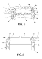
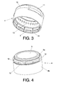
- one of the possible embodiments of the cap for oil bottles (1) or similar proposed by the invention comprises:
- the second ring-shaped extension (2a) of the pouring element (2) comprises a flexible lip (2c) which is coupled to the back of the obturator (5) and inside the housing (9) comprised between the inner wall of the first cylindrical surface (5a) of the obturator (5) and the circumferential partition wall (8) of the obturator (5), increasing the contact surface area between the second ring-shaped extension (2a) of the pouring element (2) and the capsule (4), thereby improving the watertightness of the capsule (4) in said area.
- the pouring element (2) when performing coupling between the neck (1a) of the bottle (1), the pouring element (2) and the capsule (4), the pouring element (2) includes a first extension (2b) in a radial direction towards said pouring element (2); wherein said first extension (2b) is coupled to the neck (1 a) of the bottle (1) and wherein the first ring-shaped extension (2b) has a plurality of hook-shaped projections which are coupled to another set of projections disposed at the end of the neck (1 a) of the bottle (1); likewise, it can be observed that the skirt (6) of the capsule (4) comprises a plurality of inner projections (7) which can come into contact with respective projections belonging to the neck (1a) of the bottle (1) and which prevent extraction thereof.
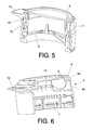
- the obturator (5) and the skirt (6) of the capsule (4) are separated by a cut (10), the obturator (5) and the skirt (6) being joined by a plurality of connections (13) of the moulded material itself, said connections (13) being breakable at the time of aperture of the cap by pushing or pulling a flange (15) disposed on the obturator (5).
- Said cut (10) extends throughout the circumference of the obturator (5) and the skirt (6), with the exception of the hinge (11) area, said area being recessed to avoid severing thereof when performing the cut (10).
Priority Applications (1)
| Application Number | Priority Date | Filing Date | Title |
|---|---|---|---|
| EP11382279A EP2559632A1 (de) | 2011-08-16 | 2011-08-16 | Deckel für Ölflaschen und ähnlichem |
Applications Claiming Priority (1)
| Application Number | Priority Date | Filing Date | Title |
|---|---|---|---|
| EP11382279A EP2559632A1 (de) | 2011-08-16 | 2011-08-16 | Deckel für Ölflaschen und ähnlichem |
Publications (1)
| Publication Number | Publication Date |
|---|---|
| EP2559632A1 true EP2559632A1 (de) | 2013-02-20 |
Family
ID=45002862
Family Applications (1)
| Application Number | Title | Priority Date | Filing Date |
|---|---|---|---|
| EP11382279A Withdrawn EP2559632A1 (de) | 2011-08-16 | 2011-08-16 | Deckel für Ölflaschen und ähnlichem |
Country Status (1)
| Country | Link |
|---|---|
| EP (1) | EP2559632A1 (de) |
Cited By (4)
| Publication number | Priority date | Publication date | Assignee | Title |
|---|---|---|---|---|
| CN106927131A (zh) * | 2016-08-26 | 2017-07-07 | 李红彪 | 具有复合盖子的容器 |
| CN107719914A (zh) * | 2017-11-07 | 2018-02-23 | 中山市华宝勒生活用品实业有限公司 | 一种拉环翻盖结构 |
| WO2019129567A1 (en) | 2017-12-28 | 2019-07-04 | Unilever Plc | Closure |
| WO2023020935A1 (de) * | 2021-08-20 | 2023-02-23 | KM Packaging GmbH | Dosierverschluss zur montage auf einem behälter und zugehöriges dosiersystem zur dosierung eines zähflüssigen produkts |
Citations (8)
| Publication number | Priority date | Publication date | Assignee | Title |
|---|---|---|---|---|
| EP0011584A1 (de) * | 1978-11-21 | 1980-05-28 | ASTRA PLASTIQUE Société Anonyme | Verbesserungen an Ausgiessverschlüssen |
| US4555048A (en) * | 1984-05-16 | 1985-11-26 | Rieke Corporation | Vented nestable pouring spout |
| US5762218A (en) * | 1994-10-06 | 1998-06-09 | Franz Rossberg | Plastic closure retained by snapping over bottle neck bead |
| ES2127076A1 (es) | 1995-10-05 | 1999-04-01 | Fernandez Eladio Mederos | Nuevo sistema para extincion de incendios y equipo movil para ponerlo en practica. |
| ES2137076A1 (es) | 1996-06-10 | 1999-12-01 | Betapack Sa | Tapon para botellas de aceite perfeccionado. |
| ES2139076T3 (es) | 1993-05-05 | 2000-02-01 | Hussmann Corp | Unidad de refrigeracion comercial modular. |
| WO2002042174A1 (de) * | 2000-11-27 | 2002-05-30 | Alpla Werke Alwin Lehner Gmbh & Co. Kg | Verschluss aus biegsamem kunststoff für behälter, insbesondere für flaschen |
| EP1460000A1 (de) * | 2003-03-20 | 2004-09-22 | Kunststoffwerk Kremsmünster GmbH + Co.KG | Klappverschluss |
-
2011
- 2011-08-16 EP EP11382279A patent/EP2559632A1/de not_active Withdrawn
Patent Citations (9)
| Publication number | Priority date | Publication date | Assignee | Title |
|---|---|---|---|---|
| EP0011584A1 (de) * | 1978-11-21 | 1980-05-28 | ASTRA PLASTIQUE Société Anonyme | Verbesserungen an Ausgiessverschlüssen |
| US4555048A (en) * | 1984-05-16 | 1985-11-26 | Rieke Corporation | Vented nestable pouring spout |
| US4555048B1 (de) * | 1984-05-16 | 1988-04-26 | ||
| ES2139076T3 (es) | 1993-05-05 | 2000-02-01 | Hussmann Corp | Unidad de refrigeracion comercial modular. |
| US5762218A (en) * | 1994-10-06 | 1998-06-09 | Franz Rossberg | Plastic closure retained by snapping over bottle neck bead |
| ES2127076A1 (es) | 1995-10-05 | 1999-04-01 | Fernandez Eladio Mederos | Nuevo sistema para extincion de incendios y equipo movil para ponerlo en practica. |
| ES2137076A1 (es) | 1996-06-10 | 1999-12-01 | Betapack Sa | Tapon para botellas de aceite perfeccionado. |
| WO2002042174A1 (de) * | 2000-11-27 | 2002-05-30 | Alpla Werke Alwin Lehner Gmbh & Co. Kg | Verschluss aus biegsamem kunststoff für behälter, insbesondere für flaschen |
| EP1460000A1 (de) * | 2003-03-20 | 2004-09-22 | Kunststoffwerk Kremsmünster GmbH + Co.KG | Klappverschluss |
Cited By (5)
| Publication number | Priority date | Publication date | Assignee | Title |
|---|---|---|---|---|
| CN106927131A (zh) * | 2016-08-26 | 2017-07-07 | 李红彪 | 具有复合盖子的容器 |
| CN107719914A (zh) * | 2017-11-07 | 2018-02-23 | 中山市华宝勒生活用品实业有限公司 | 一种拉环翻盖结构 |
| WO2019129567A1 (en) | 2017-12-28 | 2019-07-04 | Unilever Plc | Closure |
| US11383897B2 (en) | 2017-12-28 | 2022-07-12 | Conopco, Inc. | Closure |
| WO2023020935A1 (de) * | 2021-08-20 | 2023-02-23 | KM Packaging GmbH | Dosierverschluss zur montage auf einem behälter und zugehöriges dosiersystem zur dosierung eines zähflüssigen produkts |
Similar Documents
| Publication | Publication Date | Title |
|---|---|---|
| JP5804847B2 (ja) | キャップ | |
| JP5645213B2 (ja) | ヒンジキャップ | |
| JP5877557B2 (ja) | 合成樹脂製ヒンジキャップ | |
| US8608001B2 (en) | Mold-in-place two shot seal | |
| US4903849A (en) | Tamper evident cap and bottle | |
| KR20060042422A (ko) | 파열 가능한 밴드를 구비한 용기 마개 | |
| EP2559632A1 (de) | Deckel für Ölflaschen und ähnlichem | |
| CN113924257B (zh) | 用于容器的封闭盖及其制造方法 | |
| JP2013203449A (ja) | 合成樹脂製ヒンジキャップ | |
| WO2019003940A1 (ja) | プラスチックキャップ及びその製造方法 | |
| JP6102100B2 (ja) | 打栓口栓 | |
| DK2160330T3 (en) | Closing system and its method for forming | |
| WO2006070656A1 (ja) | ヒンジキャップ | |
| JP2014000996A (ja) | ヒンジキャップ | |
| MX2008016015A (es) | Procedimiento para hacer cierres de plastico y un cierre. | |
| EA006731B1 (ru) | Укупорочное устройство для бутылки с выдвижным патрубком (варианты) | |
| US11377271B2 (en) | Plastic closure part with severable membrane | |
| EP2559631B1 (de) | Dichtungsvorrichtung für Flaschen und Behälter | |
| JP4580064B2 (ja) | ヒンジ付きキャップ | |
| JP2002370765A (ja) | 合成樹脂製注出キャップ | |
| CN211618667U (zh) | 一种安全可靠的组合瓶盖及容器 | |
| JP2012214242A (ja) | 不正防止キャップ | |
| RU217474U1 (ru) | Укупорочный полимерный колпачок для бутылки | |
| JP2013086824A (ja) | 改ざん防止キャップ | |
| RU2754567C1 (ru) | Укупорочный полимерный колпачок для бутылки |
Legal Events
| Date | Code | Title | Description |
|---|---|---|---|
| PUAI | Public reference made under article 153(3) epc to a published international application that has entered the european phase |
Free format text: ORIGINAL CODE: 0009012 |
|
| AK | Designated contracting states |
Kind code of ref document: A1 Designated state(s): AL AT BE BG CH CY CZ DE DK EE ES FI FR GB GR HR HU IE IS IT LI LT LU LV MC MK MT NL NO PL PT RO RS SE SI SK SM TR |
|
| AX | Request for extension of the european patent |
Extension state: BA ME |
|
| 17P | Request for examination filed |
Effective date: 20130729 |
|
| RBV | Designated contracting states (corrected) |
Designated state(s): AL AT BE BG CH CY CZ DE DK EE ES FI FR GB GR HR HU IE IS IT LI LT LU LV MC MK MT NL NO PL PT RO RS SE SI SK SM TR |
|
| GRAP | Despatch of communication of intention to grant a patent |
Free format text: ORIGINAL CODE: EPIDOSNIGR1 |
|
| RIC1 | Information provided on ipc code assigned before grant |
Ipc: B65D 47/14 20060101ALI20131004BHEP Ipc: B65D 47/08 20060101ALI20131004BHEP Ipc: B65D 47/04 20060101ALI20131004BHEP Ipc: B65D 47/12 20060101AFI20131004BHEP |
|
| INTG | Intention to grant announced |
Effective date: 20131029 |
|
| STAA | Information on the status of an ep patent application or granted ep patent |
Free format text: STATUS: THE APPLICATION IS DEEMED TO BE WITHDRAWN |
|
| 18D | Application deemed to be withdrawn |
Effective date: 20140311 |