EP2557743A2 - Signalbeurteilungssystem und -verfahren unter Verwendung von Kanalschätzung - Google Patents
Signalbeurteilungssystem und -verfahren unter Verwendung von Kanalschätzung Download PDFInfo
- Publication number
- EP2557743A2 EP2557743A2 EP12176738A EP12176738A EP2557743A2 EP 2557743 A2 EP2557743 A2 EP 2557743A2 EP 12176738 A EP12176738 A EP 12176738A EP 12176738 A EP12176738 A EP 12176738A EP 2557743 A2 EP2557743 A2 EP 2557743A2
- Authority
- EP
- European Patent Office
- Prior art keywords
- smart antenna
- signal
- channel
- reception
- impulse response
- Prior art date
- Legal status (The legal status is an assumption and is not a legal conclusion. Google has not performed a legal analysis and makes no representation as to the accuracy of the status listed.)
- Withdrawn
Links
Images






Classifications
-
- H—ELECTRICITY
- H04—ELECTRIC COMMUNICATION TECHNIQUE
- H04B—TRANSMISSION
- H04B17/00—Monitoring; Testing
- H04B17/30—Monitoring; Testing of propagation channels
- H04B17/309—Measuring or estimating channel quality parameters
-
- H—ELECTRICITY
- H04—ELECTRIC COMMUNICATION TECHNIQUE
- H04N—PICTORIAL COMMUNICATION, e.g. TELEVISION
- H04N17/00—Diagnosis, testing or measuring for television systems or their details
- H04N17/04—Diagnosis, testing or measuring for television systems or their details for receivers
- H04N17/045—Self-contained testing apparatus
-
- H—ELECTRICITY
- H04—ELECTRIC COMMUNICATION TECHNIQUE
- H04L—TRANSMISSION OF DIGITAL INFORMATION, e.g. TELEGRAPHIC COMMUNICATION
- H04L25/00—Baseband systems
- H04L25/02—Details ; arrangements for supplying electrical power along data transmission lines
- H04L25/0202—Channel estimation
- H04L25/0212—Channel estimation of impulse response
-
- H—ELECTRICITY
- H01—ELECTRIC ELEMENTS
- H01Q—ANTENNAS, i.e. RADIO AERIALS
- H01Q3/00—Arrangements for changing or varying the orientation or the shape of the directional pattern of the waves radiated from an antenna or antenna system
- H01Q3/26—Arrangements for changing or varying the orientation or the shape of the directional pattern of the waves radiated from an antenna or antenna system varying the relative phase or relative amplitude of energisation between two or more active radiating elements; varying the distribution of energy across a radiating aperture
- H01Q3/267—Phased-array testing or checking devices
-
- H—ELECTRICITY
- H04—ELECTRIC COMMUNICATION TECHNIQUE
- H04H—BROADCAST COMMUNICATION
- H04H60/00—Arrangements for broadcast applications with a direct linking to broadcast information or broadcast space-time; Broadcast-related systems
- H04H60/09—Arrangements for device control with a direct linkage to broadcast information or to broadcast space-time; Arrangements for control of broadcast-related services
Definitions
- the present invention relates to a signal evaluation system and method.
- DTT digital terrestrial television
- Such a smart antenna comprises an active (steerable) directional antenna that is able to receive configuration data, in order to adapt and preferably optimise antenna reception characteristics for each received TV channel as it is selected.
- CEA Consumer Electronics Association
- the CEA-909 standard provides for a configuration signal from a receiver to a smart antenna for a given TV channel that comprises 2 bits for coarse direction specification, 2 bits for fine direction specification, 1 bit specifying horizontal or vertical polarisation, 2 bits to specify gain level, and 7 bits specifying the channel number.
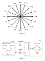
- Figure 1 illustrates how four values N of the coarse direction and the four values M of the fine direction are combined [N, M] to provide 16 directions for the steerable smart antenna. It will be appreciated that the 16 directions and the four values of N and M are a non-limiting examples.
- a signal strength of a received signal may be estimated for example from a signal to noise ratio, which may in turn for example be determined from a deviation of signals from a target symbol in a constellation of a modulation scheme in use (in a similar manner to modulation error ratio).
- Other indicators of the signal strength include a radio frequency (RF) signal strength or the gain value of an automatic gain control system.
- RF radio frequency
- indicators of signal quality include metrics such as the bit error rate (BER) of the demodulated signal.
- BER bit error rate
- a threshold bit error rate for acceptable viewing of a TV channel may be very low, requiring a considerable period of time to pass before a statistically significant estimate of BER can be obtained. In conjunction with a need to evaluate a large number of smart antenna permutations, this can undesirably prolong the process of configuring or re-configuring a smart antenna.
- a combination of signal strength and/or signal quality indicators used by the designer of a digital receiver thus determines a responsiveness of a receiver and also a quality of the received signal, as a configuration of an antenna will be selected to maximise one or both of such indicators.
- a method of evaluating signal reception is provided as per claim 1.
- a smart antenna configuration estimator is provided as per claim 11.
- a digital TV receiver 1000 is operable to receive terrestrial digital TV signals such as but not limited to those adhering to the DVB-T, DVB-T2 and/or ISDB-T standards.
- the receiver obtains these signals typically via a coaxial cable 1002 from a set-top smart antenna 1010.
- the smart antenna 1010 comprises an antenna controller 1020 and a steerable antenna 1030, such as for example an antenna array steerable using phase delays set by the antenna controller.
- the digital TV receiver then sends configuration data according to the CEA-909 standard to the smart antenna using a control cable 1004.
- an initial process of evaluating and selecting a configuration of the smart antenna breaks down into three parts.
- the smart antenna For a given RF channel, for each configuration of the smart antenna, monitor an indicator of signal strength and/or signal quality as described previously. Secondly, select the configuration of the smart antenna that generates the best signal strength and/or signal quality, or some other criterion based on such measurements. Thirdly, store this configuration in association with the channel number, and transmit it to the smart antenna as required using the CEA-909 standard.
- CIR channel impulse response
- OFDM orthogonal frequency division multiplexing
- pilot signals are formatted on certain sub-carriers of an OFDM symbol such that when performing an inverse FFT, an estimate of the CIR can be obtained. Consequently the CIR can be obtained from an existing channel estimation already being performed for channel equalisation (i.e. for purposes other than smart antenna configuration, such as normal processing in the receiver chain).
- Figure 3 shows a typical CIR for an RF channel in multi-path conditions, with a normalised response on the y-axis and time (in milliseconds) on the x-axis.
- samples of the response for the signal from the main path 301, as well as responses for longer and shorter paths 303, 305, can be discerned.
- responses to noise and other interference 307 can be seen.
- the response values have been normalised to the main path response.
- a quality indicator or Q-factor is derived as the ratio of a response for a main signal path (or, more generally, the peak sample in the CIR) to the mean of the remaining response, including the response for signals from other paths.
- this Q-factor does not quantify a signal to noise ratio, but rather quantifies the ratio between a main signal path (presumed to correspond to the peak sample in the CIR), and the additional signal paths and other remaining responses of a channel impulse response.
- the Q-factor better serves to distinguish the distribution of the signal strength over multiple signal paths since, for the same overall RF signal strength, the Q-factor increases when more signal strength is concentrated in the main path.
- reception of a terrestrial digital TV broadcast by steering the antenna to [0,0] may result in receiving three signal paths of equal strength and overall strength N.
- steering the antenna to [0,1] may result in receiving three signal paths where a main signal path was stronger than before and the other signal paths were weaker, but sum to an overall strength N-1 .
- the systems of the prior art may select the sub-optimal direction [0, 0], whereas the above described Q-factor will select position [0,1] as a better configuration.
- Q dB CIR max dB - CIR mean dB .
- Figures 4A and 4B illustrate the Q-factor in dB for CIR power at two different smart antenna configurations.
- normalising the power to the maximum response makes CIR max 0dB in each case.
- the Q-factor is improved by nearly 6dB.
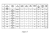
- Figure 5 shows a table listing the smart antenna configuration settings for receiving eight DVB-T channels obtained during a test of a digital TV receiver and smart antenna operating in accordance with an embodiment of the present invention.
- Two of the channels are weaker, duplicate channels equivalent to channels 4 and 8.
- the signal strength for channels 1 and 4 are the same, their evaluated Q-Factors differ by 5dB, reflecting the different multi-path conditions for each signal.
- the Q factor clearly identifies channel 4 as preferable to channel 1.
- channels 3-8 all also show good signal quality based on the slower estimation produced by evaluating the modulation error ratio.
- An orthogonal frequency division multiplexed (OFDM) signal is received by an antenna 100 and detected by a tuner 102 before being converted into digital form by an analogue-to-digital converter 104.
- a guard interval removal processor 106 removes a guard interval from a received OFDM symbol, before modulation symbols representing the data are recovered from each received OFDM symbol using a Fast Fourier Transform (FFT) processor 108 in combination with a channel estimator and corrector 110 and an embedded-signalling extraction (decoding) unit 111.
- FFT Fast Fourier Transform
- decoding embedded-signalling extraction
- a frame de-mapper 114 then separates the modulation symbols transmitted in different frames of the time division multiplexed structure of the OFDM transmission interface into logical channels, which are then time de-interleaved by a time de-interleaver 115 and then a further deinterleaver called a cell deinteraleaver 116.
- a cyclic delay removal unit 117 then removes a cyclic shift if introduced into the data at the transmitter.
- the demodulated data is then recovered from a de-mapper 118 from the modulation symbols and to produce a bit stream for each channel.
- a bit de-interleaver 120 then reverses any bit interleaving in the signal.
- an error correction decoder 121 is arranged to correct errors and recovers an estimate of the source data.
- Figure 6 also shows a configuration estimator 125 that receives the CIR or CIR power for the current channel as described previously, and which is operable to estimate and select a preferred smart antenna configuration.
- This configuration is then formatted and transmitted to the smart antenna (for example via USB cable 1004) by a CEA-909 compliant transmitter 127.
- a CPU not shown
- the configuration estimator comprises dedicated hardware
- the CEA-909 compliant transmitter may be incorporated within the configuration estimator.
- Other arrangements of hardware and software will be apparent to the skilled person in the art.
- any suitable conventional digital TV receiver that as a consequence of its normal reception processing generates a CIR or CIR power or data from which they may be derived (for example during channel estimation) may be adapted to comprise a configuration estimator and CEA-909 compliant transmitter in a similar manner to that described above.
- the initial scanning process conducted by such a digital TV receiver comprises the following steps.
- a first step s3210 the digital TV receiver is initialised for reception from the next of N RF channels to scan, starting with the first channel in the sequence. If required, any initial handshaking process with the smart antenna is also performed.
- the configuration estimator implements a so-called blind search (see reference to Figure 8 below) to estimate the Q-value for some or preferably all of the directions available to the smart antenna.
- this blind search is performed first at the lowest of four gain settings available to the smart antenna under CEA-909. The result of the blind search is a selected direction Dir Q for the smart antenna corresponding to the largest detected Q-value.
- the following four optional steps provide a graceful fallback position for the digital TV receiver in the event that there is an unanticipated problem with the Q-factor estimation. For example, an initial blind search may be performed omitting these steps in order to obtain a quick set of results, and then the search process may be performed again using these optional steps as a background activity at a subsequent time.
- a corresponding modulation error detection measurement can be taken for the selected antenna direction.
- the Q-factor for this direction Q Q can also be re-estimated at this point to provide a closer correspondence of RF conditions for these two measurements.
- a direction Dir RF for the smart antenna may then be selected based upon the highest RF signal strength (for example as measured in parallel during step s3220 above).
- step s3230 may occur after step s3240.
- a corresponding modulation error detection measurement can be taken for this second selected antenna direction.
- the Q-factor for this direction Q RF
- Q RF the Q-factor for this direction
- the configuration estimator compares MER Q to MER RF , and Dir Q is finally selected if MER Q +0.5 > MER RF (where the MER values are in dB); otherwise, Dir RF is finally selected. That is to say, there is a 0.5dB bias in favour of choosing the Q-Factor configuration selection. Hence the direction based upon the Q-factor estimate is selected unless it appears to significantly (e.g. by 0.5 dB) underperform with respect to the RF signal strength estimate. It will be appreciated that this bias value is non-limiting and may be empirically determined by the skilled person for a particular transmission scheme, or may be ommitted.
- the corresponding re-estimated Q-Factor (Q RF or Q Q ) may be selected as the Q-factor for this channel.
- a preferred gain setting is evaluated (see reference to Figure 9 below) and the configuration of the smart antenna for the present channel is updated accordingly.
- the configuration for the current channel is stored in a memory (not shown) of the digital TV receiver.
- the configuration typically includes but is not limited to:
- a ninth step s3290 the evaluation repeats for the next channel until all N RF channels are scanned.
- various exit conditions may be considered as optional steps in the above process, such as for example to mark a channel as empty and move to the next when no resolvable signal is detected for any antenna direction and optionally also for any gain level.
- the so-called blind search conducted by the configuration estimator comprises the following steps.
- the digital TV receiver performs a simple tuning operation to detect if a demodulation lock can be achieved for the current configuration. If not then optionally the process can skip to the fifth step below.
- the configuration estimator evaluates the Q-factor Q k for the current smart antenna configuration (see reference to Figure 10 below).
- the configuration estimator evaluates the RF signal strength RF k for the current smart antenna configuration. It will be appreciated with reference to Figure 6 that any suitable data link to obtain the RF signal strength value from elsewhere in the digital TV receiver can be provided.
- a fifth step s3350 the CEA-909 direction values are incremented in a nested loop (fine, then coarse) for respective values 0, 1, 2, 3, to generate in turn the 16 combinations illustrated in Figure 1 .
- the first and third steps and optionally the second and fourth steps above are then repeated with the current direction values.
- the configuration counter k is also incremented.
- the configuration estimator also returns Q MAX .
- the configuration estimator also returns RF MAX .
- evaluation of the preferred gain setting by the configuration estimator comprises the following steps.
- a first step s3410 the next smart antenna direction values in the CEA-909 format [coarse, fine] are set for the selected direction Dir Q or optionally Dir RF (see previously herein), and the gain is set to the lowest of four settings (0, 1, 2, 3) available in CEA-909. These configuration settings are then sent to the smart antenna.
- the digital TV receiver performs a simple tuning operation. It is assumed here that a demodulation lock is achieved for the selected direction, but of course this condition can be explicitly checked for and if so, where no lock is achieved then the current gain value can be bypassed.
- a third step s3430 the signal to noise ratio SNR k for the current configuration is recorded.
- SNR scales with gain for the same multi-path conditions. Therefore as the smart antenna is not changing direction during evaluation of the preferred gain, SNR is a convenient metric for performance in these circumstances.
- evaluation of the Q-factor by the configuration estimator comprises the following steps.
- the channel impulse response is obtained from the existing conventional receiver chain of the digital TV receiver, such as for example from the channel estimator 110.
- the CIR data is directly available, but alternatively the data from the receiver chain may require processing; for example if only a frequency impulse response is available in the receiver chain then the configuration estimator may perform an inverse FFT to obtain the CIR.
- the CIR may also take the form of CIR power in dB.
- a second step s3520 the maximum value in the CIR is found. This is assumed to be caused by the main signal path.
- a third step s3530 the mean of the CIR, including sample values corresponding to additional signal paths, is calculated.
- the mean can exclude the maximum value found in the previous step.
- the Q-factor is calculated in accordance with equation 1 or equation 2 above as the ratio of the maximum value of the channel input response to the mean value of the channel input response, where the mean can be biased or unbiased.
- the scanning function of Figure 7 is able to detect a set of preferred configuration variables for each channel on the digital TV receiver, by evaluating the best smart antenna direction according to the measured Q value and subsequently the best gain value.
- this can be conducted in parallel with another measurement scheme (such as one based on RF signal strength) to provide a failsafe.
- this shows a table comparing the reception performance for six DVB-T channels (corresponding to channels 3-8 in Figure 5 ) for a digital TV receiver first using a smart antenna configured according to an embodiment of the present invention and secondly using a conventional omni-directional antenna.
- the performance for both scenarios is identically measured using MER.
- the system configured according to an embodiment of the present invention consistently outperforms the omni-directional antenna, with an average performance improvement over all six RF channels of 10dB. Notably, this improvement meant that all six channels were viewable using the smart antenna, whilst none were viewable using the omni-directional antenna.
- the multi-path conditions that the Q-factor measurement can distinguish for different smart antenna directions may not be fixed. That is to say, the multiple transmission paths between transmitter and receiver may change over time. In the long term, this may occur due to seasonal variations in atmospheric conditions and ground conditions, urban construction, or refurnishing of the room in which the smart antenna is located. In the shorter term, transmission paths may also be affected by where people sit in a room, and of course by the smart antenna being knocked or deliberately moved.
- the configuration settings selected for the smart antenna for a particular channel are re-evaluated periodically (hereafter 'tracked').
- subsequently the user of the TV will expect to be able to watch their desired channel when they turn the TV on.
- testing may be triggered by one or more events.
- testing may be periodic (for example, hourly or daily) or may be user-driven (for example when switching to a channel or by selection from a menu) or scheduled (for example to occur during a period prior to a scheduled recording of a programme on a channel), or may be measurement driven (for example when an ongoing MER or BER measurement drops below a predetermined absolute or relative threshold).
- a timer is provided to prevent additional testing in response to a subsequent event within a minimum subsequent period.
- any of the above triggers may be referred to as 'events'.
- direction testing may optionally be prevented when a measurement such as MER or BER indicates that the current reception is already very good (e.g. above a first predetermined threshold) and that a change is not necessary, or counter intuitively when MER or BER measures indicate that current reception is bad (e.g. below a second predetermined threshold) and only just adequate to display the signal, on the grounds that changing direction may make the reception worse and pass the signal quality through the 'brick wall' of reception performance noted previously, thereby severely impacting the user's viewing of a channel.
- a measurement such as MER or BER indicates that the current reception is already very good (e.g. above a first predetermined threshold) and that a change is not necessary, or counter intuitively when MER or BER measures indicate that current reception is bad (e.g. below a second predetermined threshold) and only just adequate to display the signal, on the grounds that changing direction may make the reception worse and pass the signal quality through the 'brick wall' of reception performance noted previously, thereby severely impacting the user's
- the gain level or levels adjacent to the current gain level can be tested. Again, one or more similar triggering events can be used. In the case where the event is a periodic trigger, optionally this can be more frequent than for the directional test.
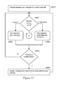
- a configuration tracking process in accordance with an embodiment of the present invention comprises the following steps.
- the digital TV receiver is initialised for reception on the current channel (either the channel selected by the receiver at start-up, or a user-selected channel).
- the stored smart antenna configurations for a selected channel are used to set up the smart antenna.
- an event monitor 129 monitors whether a triggering event has occurred that would initiate a test of the current gain setting and / or a testing of the current direction setting of the smart antenna.
- the event may be a periodic one (managed by one or more timers in the event monitor), or may be a user-driven one, or a scheduled one, or a response to a measurement.
- the event monitor function may be implemented by a CPU of the digital TV receiver.
- a detected event is to trigger a gain test (for example when a periodic gain test timer resets)
- a gain test is implemented (see reference to Figure 13 below).
- a direction test is implemented (see reference to Figures 14A and 14B below).
- a fifth step s3850 The system checks whether the gain or the direction should change as a result of their respective test, and if so in a sixth step s3860 the smart antenna configuration is updated and sent to the antenna, and is also stored by the digital TV receiver in memory.
- the testing system then loops back to monitoring step 3820.
- the smart antenna is re-configured back to the existing gain or direction setting afterwards.
- the fifth step s3850 is omitted whilst the sixth step s3860 is still implemented. This has the effect of reverting the smart antenna back to the current setting if the current setting remains the best after testing.
- the step of re-storing the same setting can be bypassed as being redundant.
- the digital TV receiver can detect whether the connected TV is currently on (i.e. if the receiver is being used to view the channel at the time); if not, then in a predetermined period prior to recording the scheduled programme, the digital TV receiver can in principle perform, for the specific channel, a full direction and gain test as per the scanning process of Figure 7 , as the user will not be affected. This will ensure the best reception for the recorded programme, in the user's absence.
- the digital TV receiver and the smart antenna are operable to receive a second channel simultaneously (e.g. where the digital TV receiver has two tuners and the smart antenna can apply two sets of phase delays to parallel copies of the received signal to receive from two directions), then the digital TV receiver can similarly perform a re-evaluation process for channels that are not currently being viewed. As noted above, because this does not affect current viewing, such re-evaluation can encompass more than just the current and adjacent directions for a respective channel. Typically, the digital TV receiver may re-evaluate the channels adjacent to the currently viewed channels and also any channels marked as favourites (if this facility exists) on the basis that these are the most likely to be subsequently viewed by a user.
- a tracking gain test in accordance with an embodiment of the present invention comprises the following steps.
- a first step s3910 if the SNR value for the current configuration SNR 0 is not already stored in memory, then is it measured (i.e. for the original gain value).
- the first adjacent gain value is selected and the smart antenna is updated.
- the SNR for the updated configuration SNR 1 is then measured. For an original gain value of 0, the adjacent value is 1. For an original gain value of 3, the adjacent value is 2.
- a second adjacent gain value is also available and is selected, and the smart antenna is updated again.
- the SNR for the second updated configuration SNR 2 is then measured.
- a fourth step s3940 the largest measured SNR is detected and the corresponding gain value is returned to the tracking process as the new gain value for the smart antenna configuration.
- the fourth step s3850 of Figure 12 (directional testing) comprises the following sub-steps.
- a direction tracking function is called (see reference to Figure 14B below). Then at step s3842, if the tracking function indicates that a different direction may be preferable to the current direction, then at steps s3843 and s3844, MER measurements for the current direction (MER old ) and the direction indicated by the direction tracking function (MER new ) are obtained. Then at step s3845, these MER measurements are compared, with a small bias ⁇ favouring the existing direction. This bias is typically in the order of 0.1 to 0.5 dB. On the basis of this comparison, either the old or new direction are stored at step s3846 in the current channel memory.
- the above process can be repeated after a short predefined interval (for example 30 seconds) to take account of the possibility that a transient event (such as a person moving in the room, or a passing vehicle) affected the previous set of results.
- a transient event such as a person moving in the room, or a passing vehicle
- the most favourable direction out of the two separate testing runs may be selected.
- a coarse direction test may be performed on a wider range of directions, and optionally all directions, in an attempt to find an acceptable reception direction.
- a tracking direction test in accordance with an embodiment of the present invention comprises the following steps.
- a first step s4010 the Q-factor value for the current configuration Q 0 is measured (i.e. for the original smart antenna direction value) as described previously herein.
- the first adjacent direction value is selected and the smart antenna is updated.
- the Q-factor for the updated configuration Q 1 is then measured. Hence, for example, if the original antenna direction value had been [0, 0], then the first adjacent direction value may be [3, 3].
- a third step s4030 the second adjacent direction value is selected and the smart antenna is updated.
- the Q-factor for the updated configuration Q 2 is then measured.
- the second adjacent direction value would be [0, 1].
- the Q-factor for each direction may be measured a plurality of times and averaged.
- the interval between such measurements may be one ranging from between consecutive signal frames (i.e. consecutive CIR evaluations) to an order of several seconds or even minutes.
- the purpose is to mitigate for any ongoing (short-term) variations in the multi-path conditions for that channel during the evaluation process.
- a fourth step s4040 the direction value associated with the largest Q-factor (or average Q-factor) is returned to the tracking process as the new direction value for the smart antenna configuration.
- the tracking process of Figure 12 is able to track drifts in the preferred direction and gain of a smart antenna during normal use of the digital TV receiver, whilst advantageously limiting the visible effect of such tracking for the user.
- a method of evaluating a quality value with which a television signal is received comprises obtaining an estimate of an impulse response of a channel through which the television signal has passed to a receiver (s3510), finding a maximum value of the channel impulse response, the maximum value corresponding (or assumed to correspond) to a main signal path (s3520), calculating a mean of values of the channel impulse response comprising channel impulse response values corresponding to one or more additional signal paths (s3530), and calculating the quality value as the ratio of the maximum value to the mean of values of the channel impulse response (s3540).
- the channel impulse response is obtained from a channel equalisation process associated with reception of the signal.
- a smart antenna configuration process for a predetermined channel comprises initialising a smart antenna to receive signals from one of a plurality of available directions (s3310), evaluating signal reception at that direction (using the above method) (s3330), storing the quality value in association with that direction, and repeating this for some or all of the available directions (s3350).
- evaluation of signal reception for a particular direction may not be performed if the receiver cannot achieve demodulation lock on the signal (s3320).
- the configuration process can then either select the direction having the largest quality value, and configuring the smart antenna accordingly; or evaluate an RF signal strength for each of the plurality of available directions (s3340), store the respective RF signal strength in association with each direction, and for the direction associated with the largest quality value and for the direction associated with the largest RF signal strength, evaluate a common reception performance metric (s3230, s3250), and select the direction evaluated to have the best reception performance by the common reception performance metric, before configuring the smart antenna accordingly (s3280).
- selection of the direction evaluated to have the best reception performance by the common reception performance metric is biased in favour of the direction associated with the largest quality value by a predetermined bias amount (s3260).
- the above process can also configure the gain by configuring the smart antenna to use the selected direction and the lowest of a predetermined set of gain values (s3410), and; estimating the signal to noise ratio for the configuration (s3430), storing the signal to noise ratio in association with the gain value, repeating the configuration, estimation and storage steps for each subsequent gain value in the predetermined set of gain values (s3440), and then selecting the gain value associated with the largest signal to noise ratio (s3450).
- the process is performed for a smart antenna that is configured in accordance with a CEA-909 standard.
- a smart antenna configuration estimator (125) for use in a digital TV receiver (1000) comprises data input means (such as a data link and input memory buffer or the like) operable to obtain an estimate of a channel impulse response from the receiver, maximum finding means (such as a CPU or dedicated hardware) operable to find the maximum value of the CIR comprising (or assumed to comprise) a response to a main signal path, averaging means (again a CPU or dedicated hardware) operable to calculate a mean of values of the CIR comprising responses to one or more additional signal paths, and ratio calculating means (again a CPU or dedicated hardware) operable to calculate a quality value as the ratio of the maximum to the mean.
- data input means such as a data link and input memory buffer or the like
- maximum finding means such as a CPU or dedicated hardware
- averaging means operable to calculate a mean of values of the CIR comprising responses to one or more additional signal paths
- ratio calculating means (again a CPU or dedicated hardware) operable to calculate a quality value as the
- a digital television receiver can comprise a smart antenna signalling means (127) operable to send to a smart antenna (1010) configuration data specifying one of a plurality of reception directions available to the smart antenna, a smart antenna configuration estimator such as that described above, and a memory operable to store a quality value in association with the specified reception direction, and the digital television receiver is operable for a predetermined RF channel to instruct the smart antenna signalling means to specify in turn some or all of the reception directions available to the smart antenna and to instruct the smart antenna configuration estimator to evaluate a quality value for each respective direction.
- the digital television receiver can then select (for future reception of signals on the predetermined RF channel) the reception direction associated with the largest quality value.
- the digital television receiver can comprise a signal evaluation means (CPU, dedicated hardware, or part of an existing receiver chain) operable to estimate a received RF signal strength, and in which the memory is operable to store the estimated RF signal strength in association with the specified reception direction, and reception performance evaluation means (CPU or dedicated hardware) operable, for the direction associated with the largest quality value and for the direction associated with the largest RF signal strength, to evaluate a reception performance, and in which the digital television receiver is operable to select (again for future reception of signals on the predetermined RF channel) the reception direction associated with the best reception performance as evaluated by the common reception performance metric.
- selection of the direction evaluated to have the best reception performance by the common reception performance metric can be biased in favour of the direction associated with the largest quality value by a predetermined bias amount.
- the methods disclosed herein may be carried out on conventional hardware suitably adapted as applicable by software instruction or by the inclusion or substitution of dedicated hardware.
- the event monitor and/or the configuration estimator may be dedicated hardware, or may be implemented wholly or partially in software running on a CPU of the digital TV receiver.
- the required adaptation to existing parts of a conventional equivalent device may be implemented in the form of a computer program product or similar object of manufacture comprising processor implementable instructions stored on a data carrier such as a floppy disk, optical disk, hard disk, PROM, RAM, flash memory or any combination of these or other storage media, or transmitted via data signals on a network such as an Ethernet, a wireless network, the Internet, or any combination of these of other networks, or realised in hardware as an ASIC (application specific integrated circuit) or an FPGA (field programmable gate array) or other configurable circuit suitable to use in adapting the conventional equivalent device.
- a data carrier such as a floppy disk, optical disk, hard disk, PROM, RAM, flash memory or any combination of these or other storage media
- a network such as an Ethernet, a wireless network, the Internet, or any combination of these of other networks, or realised in hardware as an ASIC (application specific integrated circuit) or an FPGA (field programmable gate array) or other configurable circuit suitable to use in adapting the conventional equivalent device.
Landscapes
- Engineering & Computer Science (AREA)
- Signal Processing (AREA)
- Computer Networks & Wireless Communication (AREA)
- Power Engineering (AREA)
- General Health & Medical Sciences (AREA)
- Biomedical Technology (AREA)
- Health & Medical Sciences (AREA)
- Multimedia (AREA)
- Quality & Reliability (AREA)
- Physics & Mathematics (AREA)
- Electromagnetism (AREA)
- Radio Transmission System (AREA)
- Circuits Of Receivers In General (AREA)
Applications Claiming Priority (1)
| Application Number | Priority Date | Filing Date | Title |
|---|---|---|---|
| GB1113912.8A GB2493563A (en) | 2011-08-12 | 2011-08-12 | Evaluation of signal quality factor using maximum and mean channel impulse response values |
Publications (1)
| Publication Number | Publication Date |
|---|---|
| EP2557743A2 true EP2557743A2 (de) | 2013-02-13 |
Family
ID=44764412
Family Applications (1)
| Application Number | Title | Priority Date | Filing Date |
|---|---|---|---|
| EP12176738A Withdrawn EP2557743A2 (de) | 2011-08-12 | 2012-07-17 | Signalbeurteilungssystem und -verfahren unter Verwendung von Kanalschätzung |
Country Status (5)
| Country | Link |
|---|---|
| US (1) | US8854477B2 (de) |
| EP (1) | EP2557743A2 (de) |
| JP (1) | JP2013042497A (de) |
| CN (1) | CN102957639A (de) |
| GB (1) | GB2493563A (de) |
Families Citing this family (3)
| Publication number | Priority date | Publication date | Assignee | Title |
|---|---|---|---|---|
| US9743206B2 (en) * | 2015-06-22 | 2017-08-22 | Audyssey Laboratories, Inc. | Background noise measurement from a repeated stimulus measurement system |
| WO2020033160A1 (en) * | 2018-08-08 | 2020-02-13 | Avx Antenna, Inc. D/B/A Ethertronics, Inc. | Methods for configuring a multi-mode antenna system for multi-channel communication systems |
| US12273153B2 (en) * | 2020-03-12 | 2025-04-08 | KYOCERA AVX Components (San Diego), Inc. | System and method for surfacing channel quality indicator (CQI) data associated with a multi-mode antenna |
Family Cites Families (8)
| Publication number | Priority date | Publication date | Assignee | Title |
|---|---|---|---|---|
| KR100364783B1 (ko) * | 2000-07-28 | 2002-12-16 | 엘지전자 주식회사 | 디지털 텔레비젼 수신기 및 그 디지털 텔레비젼 수신기의안테나를 제어하는 방법 |
| US7099380B1 (en) * | 2001-11-16 | 2006-08-29 | Marvell International Ltd. | Apparatus for antenna diversity for wireless communication and method thereof |
| US7058134B2 (en) * | 2001-12-17 | 2006-06-06 | Intel Corporation | System and method for multiple signal carrier time domain channel estimation |
| CN100464607C (zh) * | 2003-04-25 | 2009-02-25 | 富士通株式会社 | 用于将选自多个接收装置的接收装置的数据分配给共享信道的发送装置 |
| KR100583240B1 (ko) * | 2004-11-26 | 2006-05-25 | 한국전자통신연구원 | 디지털 방송 수신 성능 개선을 위한 최적의 빔 선택 방법및 그를 이용한 디지털 방송 수신 장치 |
| US20060203894A1 (en) * | 2005-03-10 | 2006-09-14 | Nokia Corporation | Method and device for impulse response measurement |
| JP2008271023A (ja) * | 2007-04-18 | 2008-11-06 | Univ Of Electro-Communications | アンテナシステム |
| KR101704812B1 (ko) * | 2010-01-26 | 2017-02-10 | 삼성전자주식회사 | 통신 시스템에서 잡음 및 간섭 전력 추정 장치 및 방법 |
-
2011
- 2011-08-12 GB GB1113912.8A patent/GB2493563A/en not_active Withdrawn
-
2012
- 2012-07-17 US US13/550,906 patent/US8854477B2/en not_active Expired - Fee Related
- 2012-07-17 EP EP12176738A patent/EP2557743A2/de not_active Withdrawn
- 2012-08-09 JP JP2012177067A patent/JP2013042497A/ja active Pending
- 2012-08-13 CN CN2012102910271A patent/CN102957639A/zh active Pending
Non-Patent Citations (1)
| Title |
|---|
| None |
Also Published As
| Publication number | Publication date |
|---|---|
| US8854477B2 (en) | 2014-10-07 |
| CN102957639A (zh) | 2013-03-06 |
| GB201113912D0 (en) | 2011-09-28 |
| US20130182124A1 (en) | 2013-07-18 |
| GB2493563A (en) | 2013-02-13 |
| JP2013042497A (ja) | 2013-02-28 |
Similar Documents
| Publication | Publication Date | Title |
|---|---|---|
| EP2557701A2 (de) | System und Verfahren für Signalbeurteilung | |
| JP5446725B2 (ja) | 受信装置、受信方法、受信システム | |
| TWI452861B (zh) | 天線分集裝置與天線分集方法 | |
| US20050123083A1 (en) | Receiver, receiving method, reception control program, and storage medium | |
| US8509328B2 (en) | Reception apparatus, reception method, program, and reception system | |
| US20130169881A1 (en) | Video/broadcast data receiving system | |
| EP2557743A2 (de) | Signalbeurteilungssystem und -verfahren unter Verwendung von Kanalschätzung | |
| US9614560B2 (en) | Receiver with improved noise variance estimation | |
| JP5862922B2 (ja) | 受信装置、受信方法、およびプログラム | |
| JP2010130179A (ja) | デジタル放送受信装置 | |
| JP2009502078A (ja) | 精密ofdmシンボル同期化のための方法及び同期装置並びにofdmシンボルの受信のための方法/受信器 | |
| Regueiro et al. | SHVC and LDM techniques for HD/UHD TV indoor reception | |
| JPWO2009069420A1 (ja) | 信号復調装置、信号復調方法、半導体集積回路および受信装置 | |
| JP7240205B2 (ja) | 測定装置及びプログラム | |
| US9065577B2 (en) | Digital radio receiver system and method | |
| KR100695010B1 (ko) | 다이버시티 수신기에서 보조 등화를 이용한 최적 신호 선택장치 및 그 방법 | |
| JP2004236076A (ja) | 受信装置及び受信方法 | |
| JP2008042574A (ja) | 受信装置および遅延プロファイル検出方法 | |
| Kristel et al. | Co-channel coexistence between DVB-T/H and LTE standards in a shared frequency band | |
| Asjadi | Smart antenna-aided indoor reception of digital terrestrial TV: Test & development platform | |
| JP5884011B2 (ja) | 移動体用デジタル放送受信装置 | |
| Kratochvil et al. | Simulation and experimental testing of the DVB-T broadcasting in the SFN networks | |
| US8571156B2 (en) | Receiver apparatus | |
| Baliar et al. | Estimation of a Coarse Synchronization Performance for Signals of Digital Television Systems Based on OFDM Technology | |
| JP5478451B2 (ja) | 遅延プロファイル測定装置及びプログラム |
Legal Events
| Date | Code | Title | Description |
|---|---|---|---|
| PUAI | Public reference made under article 153(3) epc to a published international application that has entered the european phase |
Free format text: ORIGINAL CODE: 0009012 |
|
| 17P | Request for examination filed |
Effective date: 20120730 |
|
| AK | Designated contracting states |
Kind code of ref document: A2 Designated state(s): AL AT BE BG CH CY CZ DE DK EE ES FI FR GB GR HR HU IE IS IT LI LT LU LV MC MK MT NL NO PL PT RO RS SE SI SK SM TR |
|
| AX | Request for extension of the european patent |
Extension state: BA ME |
|
| STAA | Information on the status of an ep patent application or granted ep patent |
Free format text: STATUS: THE APPLICATION HAS BEEN WITHDRAWN |
|
| 18W | Application withdrawn |
Effective date: 20150122 |