EP2556974A1 - Hitch arrangement for a tow vehicle, comprising a hook body for receiving a coupling member of a towed vehicle - Google Patents
Hitch arrangement for a tow vehicle, comprising a hook body for receiving a coupling member of a towed vehicle Download PDFInfo
- Publication number
- EP2556974A1 EP2556974A1 EP20120180031 EP12180031A EP2556974A1 EP 2556974 A1 EP2556974 A1 EP 2556974A1 EP 20120180031 EP20120180031 EP 20120180031 EP 12180031 A EP12180031 A EP 12180031A EP 2556974 A1 EP2556974 A1 EP 2556974A1
- Authority
- EP
- European Patent Office
- Prior art keywords
- locking
- handcuff
- assembly
- arrangement according
- coupling member
- Prior art date
- Legal status (The legal status is an assumption and is not a legal conclusion. Google has not performed a legal analysis and makes no representation as to the accuracy of the status listed.)
- Granted
Links
- 230000008878 coupling Effects 0.000 title claims description 50
- 238000010168 coupling process Methods 0.000 title claims description 50
- 238000005859 coupling reaction Methods 0.000 title claims description 50
- 238000006073 displacement reaction Methods 0.000 claims description 6
- 230000006835 compression Effects 0.000 claims description 5
- 238000007906 compression Methods 0.000 claims description 5
- 230000000903 blocking effect Effects 0.000 description 3
- 208000031968 Cadaver Diseases 0.000 description 2
- 230000000694 effects Effects 0.000 description 2
- 230000000994 depressogenic effect Effects 0.000 description 1
- 230000009977 dual effect Effects 0.000 description 1
- 238000003780 insertion Methods 0.000 description 1
- 230000037431 insertion Effects 0.000 description 1
- 238000003754 machining Methods 0.000 description 1
- 230000002093 peripheral effect Effects 0.000 description 1
- 230000035939 shock Effects 0.000 description 1
Images


Classifications
-
- B—PERFORMING OPERATIONS; TRANSPORTING
- B60—VEHICLES IN GENERAL
- B60D—VEHICLE CONNECTIONS
- B60D1/00—Traction couplings; Hitches; Draw-gear; Towing devices
- B60D1/01—Traction couplings or hitches characterised by their type
- B60D1/06—Ball-and-socket hitches, e.g. constructional details, auxiliary devices, their arrangement on the vehicle
-
- B—PERFORMING OPERATIONS; TRANSPORTING
- B60—VEHICLES IN GENERAL
- B60D—VEHICLE CONNECTIONS
- B60D1/00—Traction couplings; Hitches; Draw-gear; Towing devices
- B60D1/24—Traction couplings; Hitches; Draw-gear; Towing devices characterised by arrangements for particular functions
- B60D1/28—Traction couplings; Hitches; Draw-gear; Towing devices characterised by arrangements for particular functions for preventing unwanted disengagement, e.g. safety appliances
-
- B—PERFORMING OPERATIONS; TRANSPORTING
- B60—VEHICLES IN GENERAL
- B60D—VEHICLE CONNECTIONS
- B60D1/00—Traction couplings; Hitches; Draw-gear; Towing devices
- B60D1/58—Auxiliary devices
- B60D1/583—Holding down means, e.g. holding down retainers
Definitions
- the invention relates to a coupling arrangement for a towing vehicle, comprising a hook body on which can be coupled a coupling member of a driven vehicle and a handcuff assembly movable between a locking position of the coupling member. in its hitched position on the hook body and a position allowing the disengagement of this coupling member of the hook body, the handcuff assembly comprising a handcuff member and a lock for locking the handcuff assembly in its position of blocking.
- the object of the invention is to propose a coupling arrangement which does not have these disadvantages.
- the coupling arrangement according to the invention is characterized in that the locking device comprises locking means of the handcuffed assembly on the hook body when the assembly is in its aforementioned locking position and in that the assembly comprises locking means of the latch device on the handcuff body when the handcuff assembly occupies its locking position, which are integrated into the handcuff assembly.
- the arrangement is characterized in that the latch device is formed by a latch which is embodied as a hood pivotally mounted on the handcuff body.
- the arrangement is characterized in that the handcuff assembly is mounted on the hook body, pivoting about a vertical axis implanted in the free upper surface of the base of the hook body.
- the arrangement is characterized in that the locking pin of the hood-shaped latch is capable of engaging in an orifice provided in the free upper surface of the hook member.
- the arrangement is characterized in that the lock is mounted on the handcuff body pivoting about an axis perpendicular to the pivot axis of the handcuff assembly on the lock body. , against a latch return spring in its locking position of the assembly handcuffs in its locking position of a coupling member.
- the arrangement is characterized in that the locking means of the aforementioned lock comprise a movable pin in the handcuff body between a locking position of the lock in its locking position by the lug of the assembly handcuffs in its locking position of a coupling member and a disengagement position of the lug in which the handcuffed assembly can rotate freely about its pivot axis.
- the arrangement is characterized in that the pin is movable to leave its locking position by manual depression in the handcuff body against a return spring.
- the arrangement is characterized in that the pin passes through a recess formed in the corresponding side wall of the hood-shaped latch, which is configured to allow in cooperation with the configuration of the pawn Locking and pivoting of the lock on the handcuff body.
- the arrangement is characterized in that the handcuff body (50) is tubular and the latch device (52) is pivotally and axially movable in the handcuff body.
- the arrangement is characterized in that the locking device comprises a locking piece which is axially movable in the handcuff body between a locking position of the handcuffed assembly in its locking position. and an unlocking position of the handcuffed and pivoting assembly between a position in which it is axially immobilized and a position in which is axially displaceable between its locking and unlocking positions, the part being axially immobilizable by pivoting in its locking position .
- the arrangement is characterized in that the locking device comprises means for returning the locking piece in its axially immobilized position in its locking position of the handcuff assembly.
- the arrangement is characterized in that the return means are formed by an elastically deformable spring in compression and in torsion, which is mounted between the locking piece and the handcuff body.
- the arrangement is characterized in that the locking device comprises a handle which allows the pivoting and the axial displacement of the locking piece.
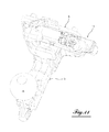
- a coupling arrangement 1 essentially comprises a ball-type hook body 3 which extends from a sole 5 for attaching the hook body to the chassis of a towing vehicle. for example, using bolts.
- the hook body 3 delimits a cradle 7 intended to receive a coupling member 9, for example in the form of an O-ring illustrated in FIG. figure 2 and being part of a driven vehicle not shown.
- the coupling arrangement also makes it possible to receive a coupling head covering the ball 4.
- the arrangement 1 further comprises a handcuffed assembly 11 for locking the coupling member 9 in its engaged position in the cradle 7, around the front hook branch carrying at its free upper end the ball 4, in accordance with the figure 2 .
- the handcuff assembly 11 is rotatably mounted about a vertical axis between its locking position of the coupling member 9, in which the assembly 11 extends in the plane of the hook member above the cradle 7 by closing it, on the one hand, and a position of release of the cradle, angularly offset from the position of the angle of for example 90 °, in accordance with Figures 5A and 5B going through the middle position of the figure 4 .
- the handcuff assembly 11 in the general form of a lever is pivotally mounted on a bolt 14 which is screwed into the substantially horizontal upper face 15 of the base 16 of the hook member, which constitutes the rear branch of the cradle, which extends from the fixing plate 5.
- the handcuff assembly 11 includes a handcuff body 18 which is rotatably mounted on the bolt 14 and a latch member 20 in the form of a hood which covers the handcuff body 18 and is pivotally mounted about an axis 21 which extends in the handcuff body 18 perpendicular to the longitudinal axis thereof.
- the axis 21 is disposed at the front end, that is to say adjacent to the ball 4, the handcuff.
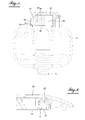
- the cover 20 is pivotable against a return torsion spring 24 between a position in which its rear portion 26 abuts against the face 15 of the hook body 16, in accordance with the Figure 7A , and a position in which the rear portion 26 is spaced from the handcuff body, as shown in FIG. Figure 7B .
- FIGS. 7A and 7B also show that the rear portion 26 of the hood 20 is folded vertically along the rear face of the handcuff body and terminates in a locking pin 30 which is dimensioned to penetrate an orifice 31 formed in the upper face 15 of the base 16 of the hook member when the cover is in its abutment position against the handcuff body by its rear portion 26, according to the Figure 7A .
- the handcuffed assembly is prevented from rotating around the axis 14 and is thus locked in its locking position of a coupling member such as the ring ring 9 of the figure 2 .
- the lug 30 is a first means of locking the handcuffed assembly 11 in its locking position of a coupling member.
- the handcuffed assembly also comprises means for locking the cover 20 in its locking position of the assembly on the hook body, in the locking position according to the Figure 7A .
- the assembly 11 comprises for this purpose a pin 33 which is mounted axially movable in a cylindrical lateral bore 36 of the handcuffed body 18.
- the pin is configured to be depressed in the bore 36, against a spring
- the head of the pin has a particular shape.
- the portion of the pin located between the outer actuating end 39 and the portion 40 engaged in the bore 36, has on the side of the portion 40 a first annular portion of a reduced diameter 41 relative to the portion 40 forming a shoulder 43 and, on the side of the actuating end 39, a second annular portion 42 of even smaller diameter.
- the pin engaged in the bore 36 of the handcuff body passes through a recess 44 in the hood sidewall, which extends, as shown in FIG. figure 8 from the lower edge 46 of the hood, perpendicularly upwards, and comprises a first portion 47 of constant width which opens at one end towards the outside and opens at its other end into a circular portion 48 whose diameter is greater than the width of the portion 47
- the diameter of the circular portion 48 is slightly greater than the diameter of the portion 41 of larger diameter of the pin 33, while the width of the portion 47 is slightly larger than the diameter of the portion of smaller diameter 42 pawn.
- the axial position of the pin 33 determines the relative position of the cap 20 on the handcuff body 18.
- the portion of larger diameter 41 of the pin is engaged in the circular portion 48 of the axial recess 44 in the side wall of the hood.
- the pin is axially in this position by the return spring 35 disposed in the bore 36 of the handcuff body and which pushes the shoulder 43 against the edge of the circular portion 48.
- the lug 30 In this position of the rear end 26 of the hood in abutment against the face 15 of the hook body 16, the lug 30 is in its position projecting from the lower edge of the cover, that is to say in its position of engagement in the hole 31 of the hook body and locking the assembly handcuffs in its locking position of a coupling member in the cradle 7.
- the cover can pivot in the direction F of its rear end spacing 26 of the face 15 of the hook body, which is the disengagement position of the lug 30 of the hole 31 of the hook body. In this hood position, the handcuff assembly 11 may be pivoted on the upper surface of the hook body about the bolt 14.
- the handcuff assembly is doubly lockable thus preventing accidental unlocking with the pin 30 and the pin 33.
- the handcuff assembly 11 is pivoted into its locking position in which the lug 30 engages in the recess 31 in the upper surface 15 of the hook body, under the effect of the torsion spring 24.
- the spring 35 pushes the pin into its cap locking position on the handcuff body, with engagement of the larger diameter portion 41 of the pin in the larger circular opening 48 of the hood.
- the invention may be modified in various ways without departing from the scope of the invention. It should also be noted that the coupling arrangement according to the invention also makes it possible to use, as a coupling member, a coupling head intended to cap the ball.
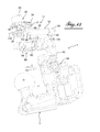
- FIGS. 9 to 18 describe a second embodiment of a coupling arrangement for a towing vehicle according to the invention.
- the coupling arrangement denoted 1 essentially comprises a ball-type hook body 3 which extends from a sole 5 of attachment of the body. hook to the chassis of a towing vehicle (not shown).
- the hook body 3 delimits a cradle 7 intended to receive a coupling member, for example in the form of an O-ring 9 ( figure 19 ) or a coupling head covering the ball 4.
- the arrangement 1 further comprises a handcuff assembly 11 for locking the coupling member in its engaged position in the cradle, around the front hook branch to its upper end free the ball 4.
- the handcuff assembly 11 is rotatably mounted about a vertical axis between its locking position of a coupling member 9, illustrated in FIGS. figures 9 , 10 and 14 to 18 , in which the assembly 11 extends in the plane of the hook body 3 above the cradle 7 by closing it, on the one hand, and, on the other hand, a position of release of the cradle, angularly offset from the blocking position by an angle of 90 ° in accordance with figure 11 , bypassing the intermediate position according to the figures 12 and 19 which allows the pivoting of the handcuff assembly towards its position of the figure 11 .
- the coupling arrangement 1 of the second embodiment implies a double security.
- the handcuffed assembly comprises a locking device for locking it in its locking position and locking means of the locking device in its position in which it locks the handcuffed assembly in the locking position.
- the latch device is configured to avoid any movement in the plane of the hook body, that is to say in height. Therefore, there is more risk of shock with the rear doors when it comes to doors type 1/3, 2/3 as existing on the van utility. This absence of any movement in height also allows the mounting of the coupling arrangement in bumpers without machining dedicated to mounting the product.
- the handcuffed assembly 11 comprises a handcuff body now denoted 50 on which is pivotably and axially displaceable a latch device 52 provided with an actuating handle 53.
- the handcuffed body 50 is formed by a lever having at one end an axis 55 which extends perpendicularly with respect to the lever and pivotally engages in the tubular support portion 56 of the hook body, located on the 5.
- the lever of the handcuffed body 50 is configured to receive the lock device 52.
- the lever is generally tubular in shape and has a first base rear portion 58 adjacent to the pivot axis 55 and a second front portion 59 which cooperates with the actuating handle 53, as well as an intermediate guiding and shoulder zone 60.
- the lock device 52 comprises a cylindrical locking piece 62 intended to be axially inserted into the handcuff body 50 and whose end 63 constitutes the actual locking element of the handcuffed assembly in its locking position, insofar as it is in abutment, laterally, against an abutment face 67 of the bearing portion 56 of the axis 55 of the hook body.
- the other end of the piece 62 is provided with a radial through hole 66 configured to allow the attachment of the piece 62 of the handle 53 by engaging an inner cylindrical tip 68 of the handle 53 in an enlarged portion 69 of the hole 66 and by means of an assembly screw 71 as shown in particular by the figures 17 and 21 .
- the screw 71 is inserted into the orifice 66 on the side diametrically opposed to the wider part 69 for receiving the endpiece 68.
- the hole 66 is provided with the insertion side of the screw 71 with a frustoconical enlargement 72 enabling the receiving the head 73 of the screw.
- the front portion 59 has a cutout 74 of appropriate shape in its wall. This cutout will be described in more detail later, after the description of the handle 53 on which it depends.
- the handle 53 is a curved piece in the form of a circular arc which has a central portion 76 of a predetermined length and, on either side of this median portion, wing-shaped lateral portions 77 and 78
- the cylindrical end piece 68 extends from the inner face of the part, radially, in the vicinity of the flange 78, as shown in particular by the figures 17 and 21 .
- the handle carries on its outer face a projecting element 80 which is the gripping means of the handle.
- the figure 17 shows the lock device 52 in its angular and axial position in which it locks the handcuff body 50 in its locking position of a Coupling member enclosed in the cradle 7.
- the tip 68 passes through a window portion 82 of the cutout 74 in the wall 87 of the tubular portion 59 of the cuff body.
- This window 82 is visible on the figures 12 and 17 on which the handle 53 and thus the latch device 52 are shown in their release positions of the handcuff body and thus release the window 82.
- the figure 21 which is a sectional view, shows the handle in its angular position of the figure 12 and makes it possible to understand the configuration of the tubular portion before 59 of the handcuff body 50.
- figures 17 and 21 thus show the handcuffed device in its two limit angular positions.
- the handle is, in the peripheral direction, supported by its flange 78 against a shoulder 84 of the tubular portion 59 at the lower edge of the window 82, as seen on the figure 12 . Since the tip 68 passes through the wall of the portion 62 radially through the window, the width of the window 82 is slightly greater than the diameter of the tip. In this angular position, the handle is axially locked by the edge 86 of the side wall 87 of the portion 62, which defines the window in the axial direction. Indeed the tip 68 would abut against the edge 86. This is a safety measure in case of accidental stress of the handle under a force in the axis of the hook body.
- This spring is disposed coaxially on the locking piece 62 of the latch device, inside the tubular portion 59 of the cuff body and is supported by one end against a shoulder 99 formed of the inner end portion 63 of this piece 62 and, at its other end, against a shoulder of stop 101 of the tubular portion 59 of the handcuff body.
- one end namely the end 103 is locked in the handcuff body, as shown in FIG. figure 18 while its other end 104 is anchored in the piece 62 of the lock device.
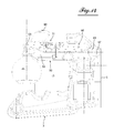
- the figure 9 illustrates the arrangement in its closed position of the cradle 7 and thus the imprisonment of a coupling member therein.
- the handcuff assembly 50 is locked in this position by the lock device 52 which then occupies its position shown in FIG. figure 17 .
- the device is held in this position by the spring 97.
- the device is axially immobilized in this position by the edge 86 of the window 82 of the handcuff body, in which is engaged the tip 68 of the handle 53.
- the end 63 of the locking device is in abutment against the lateral abutment face 67 of the hook body making it impossible to pivot the handcuffed device as shown in particular by the figure 15 .
- the handcuffed device can be pivoted from its position as shown for example by the figure 12 in the open position shown in the figure 11 in which the cuffed device 50 extends substantially perpendicular to the plane of the hook body 3.
- the spring 97 returns the handle to its locked position. figure 17 .
- the spring has a dual function, it performs both an axial return of the handle produced by the compression deformation of the spring and an angular return in the position of the spring. figure 17 because of its deformation in torsion.
- the return of the device cuffs 50 of its position of the figure 11 in its blocking position of the figure 9 is done by repeating the operations of the rotation of the handle 53 and the axial translation thereof and the pivoting of the handcuffed device 50 to the ball 4. Then releasing the handle is obtained that it locks automatically.
Landscapes
- Engineering & Computer Science (AREA)
- Transportation (AREA)
- Mechanical Engineering (AREA)
- Lock And Its Accessories (AREA)
- Hooks, Suction Cups, And Attachment By Adhesive Means (AREA)
- Agricultural Machines (AREA)
Abstract
Description
L'invention concerne un agencement d'attelage pour véhicule tracteur, comportant un corps de crochet sur lequel peut être attelé un organe d'attelage d'un véhicule mené et un ensemble menotte déplaçable entre une position de blocage de l'organe d'attelage dans sa position attelée sur le corps de crochet et une position permettant le désengagement de cet organe d'attelage du corps de crochet, l'ensemble menotte comprenant un organe de menotte et un verrou permettant le verrouillage de l'ensemble menotte dans sa position de blocage.The invention relates to a coupling arrangement for a towing vehicle, comprising a hook body on which can be coupled a coupling member of a driven vehicle and a handcuff assembly movable between a locking position of the coupling member. in its hitched position on the hook body and a position allowing the disengagement of this coupling member of the hook body, the handcuff assembly comprising a handcuff member and a lock for locking the handcuff assembly in its position of blocking.
Les agencements de ce type, qui sont connus ne satisfont pas aux exigences de sécurité d'ergonomie et d'environnement.Arrangements of this type, which are known do not meet the requirements of ergonomic safety and environment.
L'invention a pour but de proposer un agencement d'attelage qui ne présente pas ces inconvénients.The object of the invention is to propose a coupling arrangement which does not have these disadvantages.
Pour atteindre ce but, l'agencement d'attelage selon l'invention est caractérisé en ce que le dispositif verrou comprend des moyens de verrouillage de l'ensemble menotte sur le corps de crochet lorsque l'ensemble est dans sa position de blocage précité et en ce que l'ensemble comprend des moyens de verrouillage du dispositif verrou sur le corps de menotte lorsque l'ensemble menotte occupe sa position de blocage, qui sont intégrés à l'ensemble menotte.To achieve this purpose, the coupling arrangement according to the invention is characterized in that the locking device comprises locking means of the handcuffed assembly on the hook body when the assembly is in its aforementioned locking position and in that the assembly comprises locking means of the latch device on the handcuff body when the handcuff assembly occupies its locking position, which are integrated into the handcuff assembly.
Selon une caractéristique de l'invention, l'agencement est caractérisé en ce que le dispositif verrou est formé par un verrou qui est réalisé sous forme d'un capot monté pivotant sur le corps de menotte.According to a feature of the invention, the arrangement is characterized in that the latch device is formed by a latch which is embodied as a hood pivotally mounted on the handcuff body.
Selon une autre caractéristique de l'invention, l'agencement est caractérisé en ce que l'ensemble menotte est monté sur le corps de crochet, pivotant autour d'un axe vertical implanté dans la surface supérieure libre de la base du corps de crochet.According to another characteristic of the invention, the arrangement is characterized in that the handcuff assembly is mounted on the hook body, pivoting about a vertical axis implanted in the free upper surface of the base of the hook body.
Selon encore une autre caractéristique de l'invention, l'agencement est caractérisé en ce que l'ergot de verrouillage du verrou en forme de capot est susceptible de s'engager dans un orifice prévu dans la surface supérieure libre de l'organe de crochet.According to yet another characteristic of the invention, the arrangement is characterized in that the locking pin of the hood-shaped latch is capable of engaging in an orifice provided in the free upper surface of the hook member.
Selon encore une autre caractéristique de l'invention, l'agencement est caractérisé en ce que le verrou est monté sur le corps de menotte pivotant autour d'un axe perpendiculaire à l'axe de pivotement de l'ensemble menotte sur le corps de verrou, à l'encontre d'un ressort de rappel du verrou dans sa position de verrouillage de l'ensemble menotte dans sa position de blocage d'un organe d'attelage.According to yet another characteristic of the invention, the arrangement is characterized in that the lock is mounted on the handcuff body pivoting about an axis perpendicular to the pivot axis of the handcuff assembly on the lock body. , against a latch return spring in its locking position of the assembly handcuffs in its locking position of a coupling member.
Selon encore une autre caractéristique de l'invention, l'agencement est caractérisé en ce que les moyens de verrouillage du verrou précités comprennent un pion déplaçable dans le corps de menotte entre une position de verrouillage du verrou dans sa position de verrouillage par l'ergot de l'ensemble menotte dans sa position de blocage d'un organe d'attelage et une position de désengagement de l'ergot dans laquelle l'ensemble menotte peut pivoter librement autour de son axe de pivotement.According to yet another characteristic of the invention, the arrangement is characterized in that the locking means of the aforementioned lock comprise a movable pin in the handcuff body between a locking position of the lock in its locking position by the lug of the assembly handcuffs in its locking position of a coupling member and a disengagement position of the lug in which the handcuffed assembly can rotate freely about its pivot axis.
Selon encore une autre caractéristique de l'invention, l'agencement est caractérisé en ce que le pion est déplaçable pour quitter sa position de verrouillage par enfoncement manuel dans le corps de menotte à l'encontre d'un ressort de rappel.According to yet another characteristic of the invention, the arrangement is characterized in that the pin is movable to leave its locking position by manual depression in the handcuff body against a return spring.
Selon encore une autre caractéristique de l'invention, l'agencement est caractérisé en ce que le pion traverse un évidement pratiqué dans la paroi latérale correspondante du verrou en forme de capot, qui est configuré de façon à permettre en coopération avec la configuration du pion le verrouillage et le pivotement du verrou sur le corps de menotte.According to yet another characteristic of the invention, the arrangement is characterized in that the pin passes through a recess formed in the corresponding side wall of the hood-shaped latch, which is configured to allow in cooperation with the configuration of the pawn Locking and pivoting of the lock on the handcuff body.
Selon encore une autre caractéristique de l'invention, l'agencement est caractérisé en ce que le corps de menotte (50) est tubulaire et le dispositif verrou (52) est monté pivotant et axialement mobile dans le corps de menotte.According to yet another characteristic of the invention, the arrangement is characterized in that the handcuff body (50) is tubular and the latch device (52) is pivotally and axially movable in the handcuff body.
Selon encore une autre caractéristique de l'invention, l'agencement est caractérisé en ce que le dispositif verrou comprend une pièce de verrouillage qui est axialement mobile dans le corps de menotte entre une position de verrouillage de l'ensemble menotte dans sa position de blocage et une position de déverrouillage de l'ensemble menotte et pivotant entre une position dans laquelle elle est axialement immobilisée et une position dans laquelle est axialement déplaçable entre ses positions de verrouillage et de déverrouillage, la pièce étant axialement immobilisable par pivotement dans sa position de verrouillage.According to yet another characteristic of the invention, the arrangement is characterized in that the locking device comprises a locking piece which is axially movable in the handcuff body between a locking position of the handcuffed assembly in its locking position. and an unlocking position of the handcuffed and pivoting assembly between a position in which it is axially immobilized and a position in which is axially displaceable between its locking and unlocking positions, the part being axially immobilizable by pivoting in its locking position .
Selon encore une autre caractéristique de l'invention, l'agencement est caractérisé en ce que le dispositif verrou comporte des moyens de rappel de la pièce de verrouillage dans sa position axialement immobilisée dans sa position de verrouillage de l'ensemble menotte.According to yet another characteristic of the invention, the arrangement is characterized in that the locking device comprises means for returning the locking piece in its axially immobilized position in its locking position of the handcuff assembly.
Selon encore une autre caractéristique de l'invention, l'agencement est caractérisé en ce que les moyens de rappel sont formés par un ressort élastiquement déformable en compression et en torsion, qui est monté entre la pièce de verrouillage et le corps de menotte.According to yet another characteristic of the invention, the arrangement is characterized in that the return means are formed by an elastically deformable spring in compression and in torsion, which is mounted between the locking piece and the handcuff body.
Selon encore une autre caractéristique de l'invention, l'agencement est caractérisé en ce que le dispositif verrou comporte une poignée qui permet le pivotement et le déplacement axial de la pièce de verrouillage.According to yet another characteristic of the invention, the arrangement is characterized in that the locking device comprises a handle which allows the pivoting and the axial displacement of the locking piece.
L'invention sera mieux comprise, et d'autres buts, caractéristiques, détails et avantages de celle-ci apparaîtront plus clairement au cours de la description explicative qui va suivre faite en référence aux dessins schématiques annexés donnés uniquement à titre d'exemple illustrant un seul mode de réalisation de l'invention et dans lesquels :
- la
figure 1 est une vue en perspective d'un agencement d'attelage pour véhicule tracteur, selon l'invention, montrant l'ensemble menotte dans sa position de blocage d'un organe d'attelage d'un véhicule mené (non représenté) ; - la
figure 2 est une vue latérale de l'agencement selon lafigure 1 , montrant un anneau torique d'attelage engagé dans le berceau de l'agencement d'attelage ; - la
figure 3 est une vue en coupe selon la ligne III-III de lafigure 2 ; - la
figure 4 est une vue de face montrant l'ensemble menotte dans une position de rotation intermédiaire entre la position de blocage d'un organe d'attelage d'un véhicule mené et une position permettant le désengagement de l'organe d'attelage ; - les
figures 5A et5B sont deux vues frontales montrant l'ensemble menotte formé par un corps de menotte et un capot formant verrou, dans deux positions différentes ; - la
figure 6 est une vue en coupe le long de la ligne VI-VI de lafigure 2 ; - les
figures 7A et7B sont deux vues en coupe le long de la ligne VII-VII de lafigure 6 , qui montrent le capot dans deux positions de pivotement différentes ; - la
figure 8 est une vue latérale du capot. - les
figures 9 et10 sont deux vues en perspective différentes d'un deuxième mode de réalisation de l'agencement d'attelage selon l'invention et montrent l'ensemble menotte dans sa position de blocage d'un organe d'attelage d'un véhicule mené (non représenté). - la
figure 11 est une vue en perspective de l'agencement desfigures 9 et10 , montrant l'ensemble menotte dans sa position de désengagement de l'organe d'attelage ; - la
figure 12 est une vue en perspective de l'agencement d'attelage de lafigure 9 , montrant le corps de menotte dans une position intermédiaire permettant son pivotement vers sa position de lafigure 11 ; - la
figure 13 est une vue en perspective et explosée de l'agencement desfigures 9 à 12 ; - la
figure 14 est une vue latérale en direction de la flèche XIV de lafigure 9 ; - la
figure 15 est une vue en coupe partielle dans le plan médiane de l'agencement de lafigure 9 ; - la
figure 16 est une vue en coupe selon la ligne XVI-XVI de lafigure 15 ; - la
figure 17 est une vue en coupe, avec arrachement et à plus grande échelle selon la ligne XVII-XVII de lafigure 15 ; - la
figure 18 est une vue en perspective et en coupe partielle axiale de lafigure 9 ; - la
figure 19 est une vue en coupe dans le plan médian de l'agencement de lafigure 12 ; - la
figure 20 est une vue en coupe selon la ligne XX-XX de lafigure 19 ; - la
figure 21 est une vue en coupe, avec arrachement et à plus grande échelle selon la ligne XXI de lafigure 19 .
- the
figure 1 is a perspective view of a coupling arrangement for a towing vehicle, according to the invention, showing the handcuffed assembly in its locking position of a coupling member of a driven vehicle (not shown); - the
figure 2 is a side view of the arrangement according to thefigure 1 showing an O-ring coupling engaged in the cradle of the hitch arrangement; - the
figure 3 is a sectional view along line III-III of thefigure 2 ; - the
figure 4 is a front view showing the handcuffed assembly in an intermediate rotational position between the locking position of a coupling member of a driven vehicle and a position for disengagement of the coupling member; - the
Figures 5A and5B are two frontal views showing the handcuff set formed by a handcuff body and a latch cover, in two different positions; - the
figure 6 is a sectional view along the line VI-VI of thefigure 2 ; - the
Figures 7A and7B are two sectional views along line VII-VII of thefigure 6 , which show the hood in two different pivoting positions; - the
figure 8 is a side view of the hood. - the
figures 9 and10 are two different perspective views of a second embodiment of the coupling arrangement according to the invention and show the handcuffed assembly in its locking position of a coupling member of a driven vehicle (not shown ). - the
figure 11 is a perspective view of the arrangement offigures 9 and10 showing the handcuff assembly in its disengaged position of the coupling member; - the
figure 12 is a perspective view of the coupling arrangement of thefigure 9 , showing the handcuff body in an intermediate position allowing its pivoting to its position of thefigure 11 ; - the
figure 13 is a perspective and exploded view of the layout ofFigures 9 to 12 ; - the
figure 14 is a side view in the direction of the XIV arrow of thefigure 9 ; - the
figure 15 is a partial sectional view in the median plane of the arrangement of thefigure 9 ; - the
figure 16 is a sectional view along line XVI-XVI of thefigure 15 ; - the
figure 17 is a sectional view, broken away and on a larger scale according to line XVII-XVII of thefigure 15 ; - the
figure 18 is a perspective view and in partial axial section of thefigure 9 ; - the
figure 19 is a sectional view in the median plane of the layout of thefigure 12 ; - the
figure 20 is a sectional view along line XX-XX of thefigure 19 ; - the
figure 21 is a sectional view, with tearing and on a larger scale along line XXI of thefigure 19 .
Conformément aux figures, un agencement d'attelage 1 selon l'invention comporte essentiellement un corps de crochet 3 de type à boule 4 qui s'étend à partir d'une semelle 5 de fixation du corps de crochet au châssis d'un véhicule tracteur, par exemple, à l'aide de boulons. Le corps de crochet 3 délimite un berceau 7 destiné à recevoir un organe d'attelage 9, par exemple en forme d'un anneau torique illustré à la
L'agencement 1 comporte en outre un ensemble menotte 11 pour bloquer l'organe d'attelage 9 dans sa position engagée dans le berceau 7, autour de la branche de crochet avant portant à son extrémité supérieure libre la boule 4, conformément à la
Comme on le voit sur les
L'ensemble menotte 11 comprend un corps de menotte 18 qui est monté rotatif sur le boulon 14 et un organe de verrou 20 en forme d'un capot qui recouvre le corps de menotte 18 et est monté pivotant autour d'un axe 21 qui s'étend dans le corps de menotte 18 perpendiculairement à l'axe longitudinal de celui-ci. L'axe 21 est disposé au niveau de l'extrémité avant, c'est-à-dire adjacente à la boule 4, de la menotte.The
Le capot 20 est susceptible de pivoter à l'encontre d'un ressort de torsion de rappel 24 entre une position dans laquelle sa partie arrière 26 est en butée contre la face 15 du corps de crochet 16, conformément à la
Les
On comprend aisément que, dans cette situation, l'ensemble menotte est empêché de tourner autour de l'axe 14 et est donc verrouillé dans sa position de blocage d'un organe d'attelage tel que l'anneau torique 9 de la
L'ensemble menotte peut être déverrouillé en faisant pivoter le capot 20 autour de l'axe 21 dans la position dans laquelle l'ergot 30 est sorti de son orifice de réception 31, selon la
Il ressort de ce qui précède que l'ergot 30 constitue un premier moyen de verrouillage de l'ensemble menotte 11 dans sa position de blocage d'un organe d'attelage.It follows from the above that the
L'ensemble menotte comporte également des moyens de verrouillage du capot 20 dans sa position de verrouillage de l'ensemble sur le corps de crochet, dans la position de blocage selon la
Comme on le voit notamment sur la
Le pion engagé dans l'alésage 36 du corps de menotte passe à travers un évidement 44 dans la paroi latérale du capot, qui s'étend, comme le montre la
La position axiale du pion 33 détermine la position relative du capot 20 sur le corps de menotte 18. A l'état appliqué sur le corps de menotte 18 de la
Lorsque le pion 33 est poussé axialement vers l'intérieur de l'alésage 36, à l'encontre du ressort 35, sous l'effet d'une pression exercée sur son extrémité extérieure d'actionnement 39, c'est la portion 42 de diamètre plus faible qui s'engage dans la portion annulaire 48 de l'évidement du capot. Or, dans la mesure où le diamètre de la portion de plus faible diamètre 42 du pion est légèrement inférieur à la largeur de la portion rectiligne 47 de l'évidement, le capot peut pivoter dans la direction F d'écartement de son extrémité arrière 26 de la face 15 du corps de crochet, ce qui est la position de désengagement de l'ergot 30 de l'orifice 31 du corps de crochet. Dans cette position du capot, l'ensemble menotte 11 peut être amené à pivoter sur la surface supérieure du corps de crochet autour du boulon 14.When the
Il est à noter que le rappel du pion 33 dans sa position de verrouillage du capot 20 sur le corps de menotte par l'engagement de sa partie de plus grand diamètre 41 dans l'ouverture circulaire 48 de plus grande diamètre de l'évidement du capot, se fait sous la pression du ressort de compression 35 interposé entre le pion et le fond de l'alésage 35 dans le corps de menotte.It should be noted that the return of the
Il ressort de ce qui précède que l'ensemble menotte est doublement verrouillable empêchant ainsi tout déverrouillage accidentel grâce à l'ergot 30 et au pion 33.It follows from the foregoing that the handcuff assembly is doubly lockable thus preventing accidental unlocking with the
Après avoir décrit la structure de l'agencement selon l'invention, on décrira ci-après, brièvement, le fonctionnement de cet agencement.After describing the structure of the arrangement according to the invention, the operation of this arrangement will be briefly described below.
Pour assurer le blocage d'un organe d'attelage 9 dans le berceau 7 du corps de ressort, on fait pivoter l'ensemble menotte 11 dans sa position de blocage dans laquelle l'ergot 30 s'engage dans l'évidement 31 dans la surface supérieure 15 du corps de crochet, sous l'effet du ressort de torsion 24. Lorsque l'ergot est engagé dans l'orifice 31, le ressort 35 pousse le pion dans sa position de blocage du capot sur le corps de menotte, avec engagement de la partie de plus grand diamètre 41 du pion dans l'ouverture circulaire plus grande 48 du capot. Ainsi, le double verrouillage est assuré.To ensure the locking of a
Pour procéder à l'ouverture du corps de crochet, il faut successivement appuyer sur le pion 33 pour le repousser dans sa position d'engagement de la partie de plus faible diamètre 42 dans l'ouverture circulaire 48 de l'évidement du capot. Dans cette position, le capot 20 peut être relevé dans la direction de la flèche F, ce qui provoque la sortie de l'ergot 30 de l'orifice 31 du corps de crochet. L'ensemble menotte est ainsi libre pour pouvoir pivoter autour du boulon 14 dans sa position de l'ouverture du berceau 7, ce qui permet de sortir l'organe d'attelage de celui-ci.To open the hook body, it is necessary successively to press the
Bien entendu, l'invention peut être modifiée de diverses manières sans sortir du cadre de l'invention. Il est également à noter que l'agencement d'attelage selon l'invention permet aussi d'utiliser, comme organe d'attelage, une tête d'attelage destinée alors à coiffer la boule.Of course, the invention may be modified in various ways without departing from the scope of the invention. It should also be noted that the coupling arrangement according to the invention also makes it possible to use, as a coupling member, a coupling head intended to cap the ball.
Les
Comme dans le cas du premier mode de réalisation de l'invention, l'agencement d'attelage noté 1 comporte essentiellement un corps de crochet 3 du type à boule 4, qui s'étend à partir d'une semelle 5 de fixation du corps de crochet au châssis d'un véhicule tracteur (non représenté). Le corps de crochet 3 délimite un berceau 7 destiné à recevoir un organe d'attelage par exemple en forme d'un anneau torique 9 (
L'ensemble menotte 11 est monté rotatif autour d'un axe vertical entre sa position de blocage d'un organe d'attelage 9, illustrée aux
Comme dans le cas du premier mode de réalisation, l'agencement d'attelage 1 du deuxième mode de réalisation implique une double sécurité. L'ensemble menotte comporte un dispositif verrou pour son verrouillage dans sa position de blocage et des moyens de verrouillage du dispositif verrou dans sa position dans laquelle il verrouille l'ensemble menotte dans la position de blocage. Mais, différemment du premier mode de réalisation, le dispositif verrou est configuré de façon à éviter tout mouvement dans le plan du corps de crochet, c'est-à-dire en hauteur. Par conséquent, il n'y a plus de risque de choc avec les portes arrières lorsqu'il s'agit de portes de type 1/3, 2/ 3 telles qu'existantes sur les fourgons utilitaires. Cette absence de tout mouvement en hauteur permet aussi le montage de l'agencement d'attelage dans des pare-chocs sans usinage dédié au montage du produit.As in the case of the first embodiment, the
Pour atteindre cet objectif, l'ensemble menotte 11 comporte un corps de menotte maintenant noté 50 sur lequel est monté pivotant et axialement déplaçable un dispositif verrou 52 pourvu d'une poignée d'actionnement 53.To achieve this objective, the handcuffed
Plus en détail, le corps menotte 50 est formé par un levier comportant à une extrémité un axe 55 qui s'étend perpendiculairement par rapport au levier et s'engage de façon pivotante dans la partie de support tubulaire 56 du corps de crochet, située du côté de la semelle de fixation 5. Le levier du corps menotte 50 est configuré pour recevoir le dispositif verrou 52. Le levier est de forme générale tubulaire et comporte une première portion arrière de base 58 adjacente à l'axe de pivotement 55 et une deuxième portion avant 59 qui coopère avec la poignée d'actionnement 53, ainsi qu'une zone intermédiaire de guidage et d'épaulement 60.In more detail, the handcuffed
Le dispositif verrou 52 comporte une pièce cylindrique de verrouillage 62 destinée à être axialement insérée dans le corps de menotte 50 et dont l'extrémité intérieure 63 constitue l'élément de verrouillage proprement dit de l'ensemble menotte dans sa position de blocage, dans la mesure où il est en butée, latéralement, contre une face de butée 67 de la partie 56 de palier de l'axe 55 du corps de crochet. L'autre extrémité de la pièce 62 est pourvue d'un trou radial traversant 66 configuré de façon à permettre la solidarisation de la pièce 62 de la poignée 53 par engagement d'un embout cylindrique interne 68 de la poignée 53 dans une partie élargie 69 du trou 66 et au moyen d'une vis d'assemblage 71 comme le montrent notamment les
Pour permettre à la pièce de verrouillage 62 d'effectuer un mouvement de pivotement d'un angle prédéterminé, par exemple de 60°, et un mouvement axial dans le corps de menotte 50, la portion avant 59 présente une découpe 74 de forme appropriée dans sa paroi. Cette découpe sera décrite plus en détail plus loin, après la description de la poignée 53 dont elle dépend.To allow the
La poignée 53 est une pièce courbe en forme d'un arc de cercle qui comporte une portion centrale 76 d'une longueur prédéterminée et, de part et d'autre de cette partie médiane, des portions latérales en forme d'ailes 77 et 78. L'embout cylindrique 68 s'étend à partir de la face interne de la pièce, radialement, au voisinage de l'aile 78 comme le montrent notamment les
La
La
Sur la
Après avoir décrit les mesures constructives permettant le mouvement angulaire et axial du dispositif verrou, il convient de préciser que ces deux mouvements sont faits à l'encontre d'un ressort de rappel 97. Ce ressort est disposé coaxialement sur la pièce de verrouillage 62 du dispositif verrou, à l'intérieur de la partie tubulaire 59 du corps de menotte et prend appui par une extrémité contre un épaulement 99 formée de la partie d'extrémité interne 63 de cette pièce 62 et, par son autre extrémité, contre un épaulement de butée 101 de la partie tubulaire 59 du corps de menotte. Le mouvement axial de la poignée vers sa position permettant le pivotement latéral de l'ensemble menotte provoque donc la compression du ressort. D'autre part, pour pouvoir effectuer un rappel dans la direction du déplacement angulaire de la poignée, une extrémité, à savoir l'extrémité 103 est bloquée dans le corps de menotte, comme le montre la
Après la description de la structure du deuxième mode de réalisation de l'agencement d'attelage selon l'invention, on décrira ci-après le fonctionnement de celui-ci. Cette description de fonctionnement peut être brève puisqu'il ressort déjà de la description de la structure qui précède.After describing the structure of the second embodiment of the coupling arrangement according to the invention, the operation thereof will be described hereinafter. This description of operation can be brief since it already appears from the description of the preceding structure.
La
Après ces mouvements de pivotement et axial, le dispositif menotte peut être amené à pivoter de sa position que montre par exemple la
On constate ainsi que le ressort a une double fonction, il effectue à la fois un rappel axial de la poignée produit par la déformation en compression du ressort et un rappel angulaire dans la position de la
Pour l'attelage d'un véhicule mené, après la mise en place par exemple d'un anneau torique dans le berceau, le retour du dispositif menotte 50 de sa position de la
Il est à noter que le fonctionnement du deuxième mode de réalisation de l'invention ne provoque aucun mouvement d'aucune pièce en hauteur ce qui rend l'agencement parfaitement utilisable dans les cas d'application où un encombrement en hauteur est restrictif.It should be noted that the operation of the second embodiment of the invention does not cause any movement of any part in height which makes the arrangement perfectly usable in the case of application where a height requirement is restrictive.
Il est encore à noter que dans le deuxième mode de réalisation, il y a aussi la possibilité de sécuriser l'attelage formé entre le véhicule tracteur et la remorque par la mise en place d'un cadenas, condamnant toute ouverture du crochet en rendant impossible la rotation de la poignée.It is also noted that in the second embodiment, there is also the possibility of securing the hitch formed between the towing vehicle and the trailer by the establishment of a padlock, condemning any opening of the hook making it impossible the rotation of the handle.
Claims (12)
Applications Claiming Priority (1)
| Application Number | Priority Date | Filing Date | Title |
|---|---|---|---|
| FR1157279A FR2978940B1 (en) | 2011-08-10 | 2011-08-10 | A COUPLING ARRANGEMENT FOR A TRACTOR VEHICLE, COMPRISING A RECEPTION HOOK BODY OF A COUPLING MEMBER OF A VEHICLE |
Publications (2)
| Publication Number | Publication Date |
|---|---|
| EP2556974A1 true EP2556974A1 (en) | 2013-02-13 |
| EP2556974B1 EP2556974B1 (en) | 2015-11-18 |
Family
ID=46614393
Family Applications (1)
| Application Number | Title | Priority Date | Filing Date |
|---|---|---|---|
| EP12180031.2A Active EP2556974B1 (en) | 2011-08-10 | 2012-08-10 | Hitch arrangement for a tow vehicle, comprising a hook body for receiving a coupling member of a towed vehicle |
Country Status (4)
| Country | Link |
|---|---|
| EP (1) | EP2556974B1 (en) |
| ES (1) | ES2559285T3 (en) |
| FR (1) | FR2978940B1 (en) |
| PT (1) | PT2556974E (en) |
Cited By (1)
| Publication number | Priority date | Publication date | Assignee | Title |
|---|---|---|---|---|
| FR3117937A1 (en) | 2020-12-23 | 2022-06-24 | The Napka Group | coupling device for towing vehicle |
Citations (4)
| Publication number | Priority date | Publication date | Assignee | Title |
|---|---|---|---|---|
| DE3824028C1 (en) * | 1988-07-15 | 1990-02-15 | Dr.Ing.H.C. F. Porsche Ag, 7000 Stuttgart, De | Locking device for a ball-headed coupling |
| US20040239077A1 (en) * | 2003-05-28 | 2004-12-02 | Terpsma Eric M. | Trailer hitch assembly |
| DE102008031825A1 (en) * | 2007-07-10 | 2009-01-22 | Scharmüller, Josef, Ing. | Hold-down device for coupling of drawing vehicle, has fastening bolt arranged for fixation into aperture at coupling position and formed opposite to aperture, which is designed in bent-form |
| US20090039619A1 (en) * | 2007-08-06 | 2009-02-12 | Gries Thomas A | Tow hitch |
-
2011
- 2011-08-10 FR FR1157279A patent/FR2978940B1/en not_active Expired - Fee Related
-
2012
- 2012-08-10 ES ES12180031.2T patent/ES2559285T3/en active Active
- 2012-08-10 EP EP12180031.2A patent/EP2556974B1/en active Active
- 2012-08-10 PT PT121800312T patent/PT2556974E/en unknown
Patent Citations (4)
| Publication number | Priority date | Publication date | Assignee | Title |
|---|---|---|---|---|
| DE3824028C1 (en) * | 1988-07-15 | 1990-02-15 | Dr.Ing.H.C. F. Porsche Ag, 7000 Stuttgart, De | Locking device for a ball-headed coupling |
| US20040239077A1 (en) * | 2003-05-28 | 2004-12-02 | Terpsma Eric M. | Trailer hitch assembly |
| DE102008031825A1 (en) * | 2007-07-10 | 2009-01-22 | Scharmüller, Josef, Ing. | Hold-down device for coupling of drawing vehicle, has fastening bolt arranged for fixation into aperture at coupling position and formed opposite to aperture, which is designed in bent-form |
| US20090039619A1 (en) * | 2007-08-06 | 2009-02-12 | Gries Thomas A | Tow hitch |
Cited By (1)
| Publication number | Priority date | Publication date | Assignee | Title |
|---|---|---|---|---|
| FR3117937A1 (en) | 2020-12-23 | 2022-06-24 | The Napka Group | coupling device for towing vehicle |
Also Published As
| Publication number | Publication date |
|---|---|
| FR2978940B1 (en) | 2013-11-29 |
| ES2559285T3 (en) | 2016-02-11 |
| FR2978940A1 (en) | 2013-02-15 |
| PT2556974E (en) | 2016-02-15 |
| EP2556974B1 (en) | 2015-11-18 |
Similar Documents
| Publication | Publication Date | Title |
|---|---|---|
| EP0963498B2 (en) | Door lock | |
| EP2222487B1 (en) | Device for unlocking a ball hitch | |
| EP3464762B1 (en) | Device for locking and unlocking a manhole cover on a frame by means of a key, with the option of automatic keyless locking of said manhole cover on the frame | |
| WO2001028798A1 (en) | Motor vehicle fuel flap | |
| FR2697207A1 (en) | Hitch hook for the lower arm of a tractor three-point hitch. | |
| EP3050603A2 (en) | Improvement for a handle with a strap for a walking or skiing stick | |
| EP1835078B1 (en) | Road equipment | |
| EP2556974B1 (en) | Hitch arrangement for a tow vehicle, comprising a hook body for receiving a coupling member of a towed vehicle | |
| EP2009205B1 (en) | Hold-open mechanism handle, in particular for an automobile, trailer or semi-trailer | |
| EP0644340A2 (en) | Snap-hook device, particularly for mooring boats | |
| EP2045420B1 (en) | Handle system, in particular of an espagnolette, designed to be installed on the external surface of a door, such as the door of a refrigerated truck | |
| FR2905632A1 (en) | Load carrier e.g. bicycle carrier, fixing device for motor vehicle, has handling unit moved between closing and opening positions, in which fixed and mobile parts are connected and remote from each other, respectively | |
| EP2733267B1 (en) | Element for highway device, corresponding highway device and assembly | |
| EP2565353B1 (en) | Locking and unlocking device using a key of a buffer on a frame with integral cap for closing an opening of the buffer for inserting the key | |
| FR2892752A1 (en) | Cover/lid locking device for pavement manhole, has lock insert carrier removably fixed in housing to prevent access to head of operating axle, and key introduced in housing to cooperate with head for displacing stems to disengaging position | |
| FR2916008A1 (en) | COMPLEMENTARY LATCHING DEVICE INSIDE SIDE OF A DOOR ASSEMBLY OF A FIRM VOLUME OF TRANSPORT OR STORAGE | |
| EP1561888A1 (en) | Housing of an espagnolette lock having a rod abutment member | |
| EP0769598B1 (en) | Lock of the disengageable rotor type | |
| EP3379009B1 (en) | Arrangement for stopping a door for opening and closing a space, such as the cargo space of a vehicle, in the open position thereof | |
| FR2869339A1 (en) | Locking handle for door of refrigerated truck, has lock with bolt allowing locking mechanism to freely pivot between locking and unlocking positions in which arm is integrated with base and released, respectively, in locked position of lock | |
| FR2807366A1 (en) | Locking connector for motor vehicle seat mounting has hollow pin with locking balls actuated by lever frame to retain pin and attached seat on vehicle floor | |
| EP0352176B1 (en) | Locking device for a cover of a box, e.g. vehicle glove compartment | |
| EP2180120B1 (en) | Locking apparatus for rear doors of trailers or cargo containers | |
| EP1036960B1 (en) | Device for mounting and dismantling a transmission cable connecting a gearshift lever to a security bolt in a motor vehicle gearbox | |
| FR2895325A1 (en) | Antitheft, anti-intrusion and anti-overflow device for e.g. fuel tank of motor truck, has plunger tube receiving retractable filling tube that has security closure, and including transversal openings to allow through liquid during filling |
Legal Events
| Date | Code | Title | Description |
|---|---|---|---|
| PUAI | Public reference made under article 153(3) epc to a published international application that has entered the european phase |
Free format text: ORIGINAL CODE: 0009012 |
|
| AK | Designated contracting states |
Kind code of ref document: A1 Designated state(s): AL AT BE BG CH CY CZ DE DK EE ES FI FR GB GR HR HU IE IS IT LI LT LU LV MC MK MT NL NO PL PT RO RS SE SI SK SM TR |
|
| AX | Request for extension of the european patent |
Extension state: BA ME |
|
| 17P | Request for examination filed |
Effective date: 20130214 |
|
| GRAP | Despatch of communication of intention to grant a patent |
Free format text: ORIGINAL CODE: EPIDOSNIGR1 |
|
| RIC1 | Information provided on ipc code assigned before grant |
Ipc: B60D 1/58 20060101ALI20141031BHEP Ipc: B60D 1/06 20060101ALI20141031BHEP Ipc: B60D 1/28 20060101AFI20141031BHEP |
|
| INTG | Intention to grant announced |
Effective date: 20141117 |
|
| GRAS | Grant fee paid |
Free format text: ORIGINAL CODE: EPIDOSNIGR3 |
|
| GRAP | Despatch of communication of intention to grant a patent |
Free format text: ORIGINAL CODE: EPIDOSNIGR1 |
|
| INTG | Intention to grant announced |
Effective date: 20150430 |
|
| GRAP | Despatch of communication of intention to grant a patent |
Free format text: ORIGINAL CODE: EPIDOSNIGR1 |
|
| INTG | Intention to grant announced |
Effective date: 20150909 |
|
| GRAA | (expected) grant |
Free format text: ORIGINAL CODE: 0009210 |
|
| AK | Designated contracting states |
Kind code of ref document: B1 Designated state(s): AL AT BE BG CH CY CZ DE DK EE ES FI FR GB GR HR HU IE IS IT LI LT LU LV MC MK MT NL NO PL PT RO RS SE SI SK SM TR |
|
| REG | Reference to a national code |
Ref country code: GB Ref legal event code: FG4D Free format text: NOT ENGLISH |
|
| REG | Reference to a national code |
Ref country code: CH Ref legal event code: EP |
|
| REG | Reference to a national code |
Ref country code: AT Ref legal event code: REF Ref document number: 761348 Country of ref document: AT Kind code of ref document: T Effective date: 20151215 |
|
| REG | Reference to a national code |
Ref country code: IE Ref legal event code: FG4D Free format text: LANGUAGE OF EP DOCUMENT: FRENCH |
|
| REG | Reference to a national code |
Ref country code: DE Ref legal event code: R096 Ref document number: 602012012307 Country of ref document: DE |
|
| REG | Reference to a national code |
Ref country code: ES Ref legal event code: FG2A Ref document number: 2559285 Country of ref document: ES Kind code of ref document: T3 Effective date: 20160211 |
|
| REG | Reference to a national code |
Ref country code: CH Ref legal event code: NV Representative=s name: GLN S.A., CH Ref country code: PT Ref legal event code: SC4A Free format text: AVAILABILITY OF NATIONAL TRANSLATION Effective date: 20160113 |
|
| REG | Reference to a national code |
Ref country code: NL Ref legal event code: MP Effective date: 20160218 |
|
| REG | Reference to a national code |
Ref country code: LT Ref legal event code: MG4D |
|
| REG | Reference to a national code |
Ref country code: AT Ref legal event code: MK05 Ref document number: 761348 Country of ref document: AT Kind code of ref document: T Effective date: 20151118 |
|
| PG25 | Lapsed in a contracting state [announced via postgrant information from national office to epo] |
Ref country code: HR Free format text: LAPSE BECAUSE OF FAILURE TO SUBMIT A TRANSLATION OF THE DESCRIPTION OR TO PAY THE FEE WITHIN THE PRESCRIBED TIME-LIMIT Effective date: 20151118 Ref country code: LT Free format text: LAPSE BECAUSE OF FAILURE TO SUBMIT A TRANSLATION OF THE DESCRIPTION OR TO PAY THE FEE WITHIN THE PRESCRIBED TIME-LIMIT Effective date: 20151118 Ref country code: NO Free format text: LAPSE BECAUSE OF FAILURE TO SUBMIT A TRANSLATION OF THE DESCRIPTION OR TO PAY THE FEE WITHIN THE PRESCRIBED TIME-LIMIT Effective date: 20160218 Ref country code: IS Free format text: LAPSE BECAUSE OF FAILURE TO SUBMIT A TRANSLATION OF THE DESCRIPTION OR TO PAY THE FEE WITHIN THE PRESCRIBED TIME-LIMIT Effective date: 20160318 Ref country code: NL Free format text: LAPSE BECAUSE OF FAILURE TO SUBMIT A TRANSLATION OF THE DESCRIPTION OR TO PAY THE FEE WITHIN THE PRESCRIBED TIME-LIMIT Effective date: 20151118 |
|
| PG25 | Lapsed in a contracting state [announced via postgrant information from national office to epo] |
Ref country code: LV Free format text: LAPSE BECAUSE OF FAILURE TO SUBMIT A TRANSLATION OF THE DESCRIPTION OR TO PAY THE FEE WITHIN THE PRESCRIBED TIME-LIMIT Effective date: 20151118 Ref country code: AT Free format text: LAPSE BECAUSE OF FAILURE TO SUBMIT A TRANSLATION OF THE DESCRIPTION OR TO PAY THE FEE WITHIN THE PRESCRIBED TIME-LIMIT Effective date: 20151118 Ref country code: PL Free format text: LAPSE BECAUSE OF FAILURE TO SUBMIT A TRANSLATION OF THE DESCRIPTION OR TO PAY THE FEE WITHIN THE PRESCRIBED TIME-LIMIT Effective date: 20151118 Ref country code: FI Free format text: LAPSE BECAUSE OF FAILURE TO SUBMIT A TRANSLATION OF THE DESCRIPTION OR TO PAY THE FEE WITHIN THE PRESCRIBED TIME-LIMIT Effective date: 20151118 Ref country code: RS Free format text: LAPSE BECAUSE OF FAILURE TO SUBMIT A TRANSLATION OF THE DESCRIPTION OR TO PAY THE FEE WITHIN THE PRESCRIBED TIME-LIMIT Effective date: 20151118 Ref country code: GR Free format text: LAPSE BECAUSE OF FAILURE TO SUBMIT A TRANSLATION OF THE DESCRIPTION OR TO PAY THE FEE WITHIN THE PRESCRIBED TIME-LIMIT Effective date: 20160219 Ref country code: SE Free format text: LAPSE BECAUSE OF FAILURE TO SUBMIT A TRANSLATION OF THE DESCRIPTION OR TO PAY THE FEE WITHIN THE PRESCRIBED TIME-LIMIT Effective date: 20151118 |
|
| PG25 | Lapsed in a contracting state [announced via postgrant information from national office to epo] |
Ref country code: CZ Free format text: LAPSE BECAUSE OF FAILURE TO SUBMIT A TRANSLATION OF THE DESCRIPTION OR TO PAY THE FEE WITHIN THE PRESCRIBED TIME-LIMIT Effective date: 20151118 |
|
| REG | Reference to a national code |
Ref country code: DE Ref legal event code: R097 Ref document number: 602012012307 Country of ref document: DE Ref country code: FR Ref legal event code: PLFP Year of fee payment: 5 |
|
| PG25 | Lapsed in a contracting state [announced via postgrant information from national office to epo] |
Ref country code: EE Free format text: LAPSE BECAUSE OF FAILURE TO SUBMIT A TRANSLATION OF THE DESCRIPTION OR TO PAY THE FEE WITHIN THE PRESCRIBED TIME-LIMIT Effective date: 20151118 Ref country code: SM Free format text: LAPSE BECAUSE OF FAILURE TO SUBMIT A TRANSLATION OF THE DESCRIPTION OR TO PAY THE FEE WITHIN THE PRESCRIBED TIME-LIMIT Effective date: 20151118 Ref country code: RO Free format text: LAPSE BECAUSE OF FAILURE TO SUBMIT A TRANSLATION OF THE DESCRIPTION OR TO PAY THE FEE WITHIN THE PRESCRIBED TIME-LIMIT Effective date: 20151118 Ref country code: DK Free format text: LAPSE BECAUSE OF FAILURE TO SUBMIT A TRANSLATION OF THE DESCRIPTION OR TO PAY THE FEE WITHIN THE PRESCRIBED TIME-LIMIT Effective date: 20151118 Ref country code: SK Free format text: LAPSE BECAUSE OF FAILURE TO SUBMIT A TRANSLATION OF THE DESCRIPTION OR TO PAY THE FEE WITHIN THE PRESCRIBED TIME-LIMIT Effective date: 20151118 |
|
| PLBE | No opposition filed within time limit |
Free format text: ORIGINAL CODE: 0009261 |
|
| STAA | Information on the status of an ep patent application or granted ep patent |
Free format text: STATUS: NO OPPOSITION FILED WITHIN TIME LIMIT |
|
| 26N | No opposition filed |
Effective date: 20160819 |
|
| PGFP | Annual fee paid to national office [announced via postgrant information from national office to epo] |
Ref country code: GB Payment date: 20160831 Year of fee payment: 5 |
|
| PG25 | Lapsed in a contracting state [announced via postgrant information from national office to epo] |
Ref country code: SI Free format text: LAPSE BECAUSE OF FAILURE TO SUBMIT A TRANSLATION OF THE DESCRIPTION OR TO PAY THE FEE WITHIN THE PRESCRIBED TIME-LIMIT Effective date: 20151118 |
|
| REG | Reference to a national code |
Ref country code: CH Ref legal event code: PFA Owner name: POMMIER, FR Free format text: FORMER OWNER: POMMIER, FR |
|
| PG25 | Lapsed in a contracting state [announced via postgrant information from national office to epo] |
Ref country code: MC Free format text: LAPSE BECAUSE OF FAILURE TO SUBMIT A TRANSLATION OF THE DESCRIPTION OR TO PAY THE FEE WITHIN THE PRESCRIBED TIME-LIMIT Effective date: 20151118 |
|
| REG | Reference to a national code |
Ref country code: IE Ref legal event code: MM4A |
|
| PG25 | Lapsed in a contracting state [announced via postgrant information from national office to epo] |
Ref country code: IE Free format text: LAPSE BECAUSE OF NON-PAYMENT OF DUE FEES Effective date: 20160810 |
|
| REG | Reference to a national code |
Ref country code: FR Ref legal event code: PLFP Year of fee payment: 6 |
|
| PG25 | Lapsed in a contracting state [announced via postgrant information from national office to epo] |
Ref country code: LU Free format text: LAPSE BECAUSE OF NON-PAYMENT OF DUE FEES Effective date: 20160810 |
|
| GBPC | Gb: european patent ceased through non-payment of renewal fee |
Effective date: 20170810 |
|
| PG25 | Lapsed in a contracting state [announced via postgrant information from national office to epo] |
Ref country code: HU Free format text: LAPSE BECAUSE OF FAILURE TO SUBMIT A TRANSLATION OF THE DESCRIPTION OR TO PAY THE FEE WITHIN THE PRESCRIBED TIME-LIMIT; INVALID AB INITIO Effective date: 20120810 Ref country code: CY Free format text: LAPSE BECAUSE OF FAILURE TO SUBMIT A TRANSLATION OF THE DESCRIPTION OR TO PAY THE FEE WITHIN THE PRESCRIBED TIME-LIMIT Effective date: 20151118 |
|
| PG25 | Lapsed in a contracting state [announced via postgrant information from national office to epo] |
Ref country code: MK Free format text: LAPSE BECAUSE OF FAILURE TO SUBMIT A TRANSLATION OF THE DESCRIPTION OR TO PAY THE FEE WITHIN THE PRESCRIBED TIME-LIMIT Effective date: 20151118 Ref country code: TR Free format text: LAPSE BECAUSE OF FAILURE TO SUBMIT A TRANSLATION OF THE DESCRIPTION OR TO PAY THE FEE WITHIN THE PRESCRIBED TIME-LIMIT Effective date: 20151118 Ref country code: MT Free format text: LAPSE BECAUSE OF FAILURE TO SUBMIT A TRANSLATION OF THE DESCRIPTION OR TO PAY THE FEE WITHIN THE PRESCRIBED TIME-LIMIT Effective date: 20151118 |
|
| PG25 | Lapsed in a contracting state [announced via postgrant information from national office to epo] |
Ref country code: BG Free format text: LAPSE BECAUSE OF FAILURE TO SUBMIT A TRANSLATION OF THE DESCRIPTION OR TO PAY THE FEE WITHIN THE PRESCRIBED TIME-LIMIT Effective date: 20151118 Ref country code: GB Free format text: LAPSE BECAUSE OF NON-PAYMENT OF DUE FEES Effective date: 20170810 |
|
| REG | Reference to a national code |
Ref country code: FR Ref legal event code: PLFP Year of fee payment: 7 |
|
| PG25 | Lapsed in a contracting state [announced via postgrant information from national office to epo] |
Ref country code: AL Free format text: LAPSE BECAUSE OF FAILURE TO SUBMIT A TRANSLATION OF THE DESCRIPTION OR TO PAY THE FEE WITHIN THE PRESCRIBED TIME-LIMIT Effective date: 20151118 |
|
| REG | Reference to a national code |
Ref country code: CH Ref legal event code: NV Representative=s name: BOVARD SA NEUCHATEL CONSEILS EN PROPRIETE INTE, CH |
|
| P01 | Opt-out of the competence of the unified patent court (upc) registered |
Effective date: 20230518 |
|
| PGFP | Annual fee paid to national office [announced via postgrant information from national office to epo] |
Ref country code: IT Payment date: 20230829 Year of fee payment: 12 Ref country code: ES Payment date: 20230901 Year of fee payment: 12 Ref country code: CH Payment date: 20230902 Year of fee payment: 12 |
|
| PGFP | Annual fee paid to national office [announced via postgrant information from national office to epo] |
Ref country code: PT Payment date: 20230807 Year of fee payment: 12 Ref country code: FR Payment date: 20230811 Year of fee payment: 12 Ref country code: DE Payment date: 20230831 Year of fee payment: 12 Ref country code: BE Payment date: 20230824 Year of fee payment: 12 |