EP2556593B1 - Simulierter snr-verlust bei decodiertem digitalem audio im zusammenhang mit der bitfehlerrate einer drahtlosverbindung - Google Patents
Simulierter snr-verlust bei decodiertem digitalem audio im zusammenhang mit der bitfehlerrate einer drahtlosverbindung Download PDFInfo
- Publication number
- EP2556593B1 EP2556593B1 EP11710962.9A EP11710962A EP2556593B1 EP 2556593 B1 EP2556593 B1 EP 2556593B1 EP 11710962 A EP11710962 A EP 11710962A EP 2556593 B1 EP2556593 B1 EP 2556593B1
- Authority
- EP
- European Patent Office
- Prior art keywords
- digital radio
- audible
- indicator
- radio transmission
- received
- Prior art date
- Legal status (The legal status is an assumption and is not a legal conclusion. Google has not performed a legal analysis and makes no representation as to the accuracy of the status listed.)
- Active
Links
Images


Classifications
-
- H—ELECTRICITY
- H04—ELECTRIC COMMUNICATION TECHNIQUE
- H04B—TRANSMISSION
- H04B1/00—Details of transmission systems, not covered by a single one of groups H04B3/00 - H04B13/00; Details of transmission systems not characterised by the medium used for transmission
- H04B1/06—Receivers
- H04B1/10—Means associated with receiver for limiting or suppressing noise or interference
- H04B1/1027—Means associated with receiver for limiting or suppressing noise or interference assessing signal quality or detecting noise/interference for the received signal
-
- H—ELECTRICITY
- H04—ELECTRIC COMMUNICATION TECHNIQUE
- H04B—TRANSMISSION
- H04B17/00—Monitoring; Testing
-
- H—ELECTRICITY
- H04—ELECTRIC COMMUNICATION TECHNIQUE
- H04B—TRANSMISSION
- H04B1/00—Details of transmission systems, not covered by a single one of groups H04B3/00 - H04B13/00; Details of transmission systems not characterised by the medium used for transmission
- H04B1/06—Receivers
- H04B1/10—Means associated with receiver for limiting or suppressing noise or interference
-
- H—ELECTRICITY
- H04—ELECTRIC COMMUNICATION TECHNIQUE
- H04B—TRANSMISSION
- H04B17/00—Monitoring; Testing
- H04B17/20—Monitoring; Testing of receivers
- H04B17/23—Indication means, e.g. displays, alarms, audible means
Definitions
- the invention concerns radio communication method, apparatus, and system. More particularly, the invention concerns a method for a digital radio to provide an audible indicator of communication link quality.
- Analog radios provide a communication link for a baseband signal, such as an audio signal, by use of an analog radio transmitter and an analog radio receiver.
- An analog radio transmitter operates by amplifying the baseband signal, modulating the baseband signal by use of analog modulation techniques that are known in the art, frequency upconverting the modulated signal to radio frequencies, (RF), and transmitting the RF signal to an analog radio receiver.
- the analog radio receiver recovers the baseband signal by downconverting and demodulating the received RF signal. Radio operators such as public safety personnel are very familiar with the operation of analog radios.
- Analog radios are simple, but a disadvantage of analog radio is that the quality of the received radio transmission, after demodulation in order to provide a received baseband signal, is prone to be poor (e.g., noisy) in situations such as low RF received power level, low signal-to-noise (SNR) ratio, and the presence of interference.
- SNR signal-to-noise
- Receiver performance of analog radios gracefully degrades, such that the radio operator can hear increased noise on the demodulated baseband signal as the received RF signal weakens or the SNR degrades.
- the increased noise provides an aural cue to the radio operator, who may then use the aural cue to move to an area of better coverage.
- the analog radio operator is able to hear conversations of other radio operators, the radio operator may be able to get additional audio cues of quality by listening to the quality of those other conversations on the analog radio.
- digital radios employ digital modulation techniques that are known in the art in order to provide a digitized communication signal from a transmitter to a receiver.
- the digitized communication signal may include a digitized baseband voice signal, or other baseband audible signals (e.g., music), or IP-based data traffic.
- digital radios provide a relatively noise-free received demodulated baseband signal under typical operating conditions.
- Digital radios improve the received signal quality delivered to a radio operator over a wide range of received signal conditions by using error detection and correction techniques.
- Digital radios also provide other benefits compared to analog radios, e.g., more efficient spectral usage.
- the usable error detection and correction techniques may vary depending upon the type of communication and the latency, and may be implemented at different levels of a protocol stack.
- error detection and correction techniques may include an error-correcting code (ECC).
- ECC error-correcting code
- FEC forward error correction
- the transmitter encodes the data with an error-correcting code (ECC) and sends the coded message.
- ECC error-correcting code
- the receiver receives a noise-corrupted signal, and makes a maximum-likelihood estimation of the original transmitted message.
- ECC decoders are often located close to the front end of the digital radio receiver, e.g., in the first stage of digital processing after a signal has been received.
- ECC coders may also generate a bit-error rate (BER) signal or error count signal, which can be used as a feedback to gauge the quality of the received signal.
- BER bit-error rate
- the BER may be an uncoded BER, which is the bit error rate prior to ECC correction, or a coded BER which is the BER after ECC decoding and which is what is delivered to the listener.
- the uncoded BER is more useful than a coded BER for the purpose of monitoring RF link degradations, because the uncoded BER is more sensitive to such degradations.
- OpenSky uses a continuously transmitting base station with separate error correction schemes for control channel and data. Continuous monitoring of base station traffic can provide a received signal strength indicator (“RSSI”) and error numbers provided by an ECC decoder.
- RSSI received signal strength indicator
- the error detection and correction capabilities of digital radio provide high-quality baseband analog audio transmission capability, as long as the digital radio is operating within the error detection and correction limits of the decoder. This is generally seen as an advantage because it increases the useful range within which digital radios can operate compared to analog radios.
- radio operators e.g., firefighters
- Some radio operators find this shortcoming objectionable enough to decide to revert to their familiar analog systems.
- WO 97/34381 A2 discloses a radio communication method in which an alignment signal is injected into a radio communication as an additional noise.
- US 5,991,901 A discloses a digital communication method which is based on either RSSI or BER.
- a simulated RF channel noise is injected into a speaker path triggered by a "range indication" obtained through RSSI and/or BER.
- US 6,243,568 B1 discloses a portable digital communication system. An indicator is injected into audio/video signals in response to estimated signal quality. It is possible to trigger a mute function and providing extrapolated information in response to estimated signal quality.
- GB 2,307,623 A discloses an out of range indication system for digital wireless systems.
- a noise indicator is injected into an audio communication in response to a detected drop through an RSSI technique, or, as an alternative technique, through a BER technique.
- EP 1 432 154 A2 discloses a system for reducing interference between wireless devices and electronic vehicle systems.
- Embodiments of the present invention add a controlled amount of noise back into the error corrected audio output of a digital radio, in order to produce a composite audio output that simulates the operation of analog radios.
- the amount of noise is controlled by the detected quality of the signal received by the digital radio.
- the radio operator can interpret the noise as a warning that his communication is in danger of failing, and as an aural guide in finding a better area of coverage.
- One or more embodiments of the invention may provide method or apparatus to provide an audible indicator of a quality of a received digital radio transmission, including receiving a digital radio transmission in a digital radio receiver, detecting the quality of the received digital radio transmission, decoding an audible communication from the received digital radio transmission, superimposing an audible indicator onto the audible communication, to form a composite audible signal, and dynamically adjusting an amplitude of the audible indicator relative to an amplitude of the audible communication responsive to a quality of the received digital audio transmission.
- One or more embodiments of the invention may provide software stored in a memory that is coupled to a microprocessor, wherein, after reception of a digital radio transmission in a digital radio receiver, the microprocessor is programmed by the software to provide an audible indicator of a quality of the received digital radio transmission by detecting the quality of the received digital radio transmission, decoding an audible communication from the received digital radio transmission, superimposing an audible indicator onto the audible communication, to form a composite audible signal, and dynamically adjusting an amplitude of the audible indicator relative to an amplitude of the audible communication responsive to a quality of the received digital audio transmission.
- the microprocessor may be in the form of a digital signal processor.
- Optional variations of the foregoing embodiments may include: detecting the quality of the received digital radio transmission by detecting a received signal strength indicator of the received digital radio transmission; detecting the quality of the received digital radio transmission by detecting a coded bit error rate of the received digital radio transmission; and detecting the quality of the received digital radio transmission comprises detecting a signal to noise ratio of the received digital radio transmission.
- Optional variations of the foregoing embodiments may further include: comparing the quality of the received digital radio transmission to a first predetermined threshold, wherein the audible indicator is superimposed onto the audible communication only if the quality of the received digital radio transmission is below the first predetermined threshold; comparing the quality of the received digital radio transmission to a second predetermined threshold, wherein the audible indicator is superimposed onto the audible communication only if the quality of the received digital radio transmission is above the second predetermined threshold; and detecting whether the received digital radio transmission includes a communication from a remote radio operator, wherein the audible indicator is suppressed if a communication from the remote radio operator is detected.
- Optional variations of the foregoing embodiments may further include selectively disabling the audible indicator responsive to a radio operator input to the digital radio receiver.
- Optional variations of the foregoing embodiments may further include the audible indicator being one or more of a broadband noise signal, a simple tone, a complex tone, and a buzz.
- Analog radios receive an RF signal modulated by analog methods, and provide a demodulated baseband signal.
- the demodulated baseband signal includes noise that increases under increasingly degraded RF link conditions. Although generally the noise is unwanted, it beneficially provides an audible cue to degraded RF link conditions and an early warning to the possibility of loss of the communications link.
- Digital radios use digital modulation techniques to provide, via a data channel, a demodulated baseband signal that is less susceptible to degraded RF link conditions.
- Digital radios may provide a control channel in addition to the data channel.
- the control channel can be routed to the same recipients as the data channel, and/or can be routed to other recipients such as a base station controller.
- the control channel can provide a way to control settings within the digital radio, or to report back the status of the digital radio, or to provide information about connectivity and/or link quality between various digital radios that are grouped to form a network.
- the control channel can also be used to set up and control trunking (i.e., connectivity) between digital radios.
- An exemplary network may include a base station and one or more subscribers.
- the subscribers typically are mobile and are more likely to experience degraded RF link conditions.
- the base station typically is less mobile and may be in a fixed location, and therefore is less likely to experience degraded RF link conditions.
- the base station may be in charge of the network.
- a dispatcher may be used to help control the network and assign network resources.
- the demodulated baseband data channel signal may include digitized audio (e.g., voice) and/or non-audio packet data.
- the non-audio packet data may include, for instance, web pages, file transmissions, datalinks, etc., that may be intended for visual display on a screen or terminal.
- the digital radio should be able to determine whether an individual packet of data contains audio data or non-audio data, for instance by monitoring the contents of the packet itself (e.g., a header portion), or by information obtained via the control channel.
- the demodulated baseband audio signal includes little or no perceptible noise for RF link conditions within design limits, but provides little warning to the radio operator if RF link conditions degrade toward exceeding design limits.
- Embodiments of the present invention selectively add a controlled amount of noise back into the error corrected audio output of the demodulated baseband data channel of a digital radio, in order to produce a composite audio output which simulates degraded RF link conditions.
- the packet data will not be audibly monitored by a human user. Adding noise to the data channel when it is carrying non-audio data would be ineffective to warn a user of degraded link conditions, and would further degrade the non-audio packet data. Therefore, embodiments of the present invention can inhibit the addition of a controlled amount of noise back into the error corrected output of the demodulated baseband data channel of a digital radio, on a packet-by-packet basis, if it is determined that a particular packet contains non-audio data.
- non-audio packet data it may be desirable to provide to a non-audio packet data subscriber and/or base station an alternate indication (e.g., an annunciator) of degraded link conditions, rather than adding the controlled amount of noise as is used for audio data.
- an alternate indication e.g., an annunciator
- the annunciator can take one or more forms such as a pop-up window on a terminal in order to alert a user of degraded link conditions, or a chart/bars/bar-graph of RF link quality, or some change in attribute of at least a portion of a terminal display (e.g., changing text or screen color, or making text be bolder, bigger, blinking, displaying a status bar, etc.), or an audio indication that is separate from and not added to the received non-audio packet data (e.g., a chirp, alarm sound, recorded voice alert, tone, buzz, etc.).
- noise may be inhibited if a digital radio is monitoring the control channel at a base station without receiving the data channel.
- a digital radio e.g., the base station
- a second digital radio e.g., a subscriber unit
- the RSSI value can be used as a control to inject a specified level of noise into the audio output of the radio.
- the noise level can be made inversely proportional to the signal strength so that as the signal strength decreases, noise increases. The radio operator can then move to a position of better signal strength without needing to look at his radio.
- the error correction algorithm implemented in the receiver can report how many errors the algorithm found, and how many errors the algorithm corrected. As performance degrades, the number of both kinds of errors will rise. The number of errors of either kind, or both together, can therefore be used to control the amplitude of added noise to the composite audio output.
- This measurement metric is suitable for both low signal powers, and for conditions that cause errors without necessarily causing a loss of signal power. An example of the latter is errors that may be induced by the presence of strong adjacent channel interference.
- a combined approach can also be used, in which both the RSSI and the count of detected and/or corrected errors can be used to determine the amount of injected noise.
- This approach has the advantage of indicating failing communications both in the presence of strong interference, as well as in weak RF signal strength regions.
- a separate indicator such as a simple tone, complex tone, buzz or the like could also be used to indicate interference, wherein the volume of the separate indicator depends upon the error count or BER.
- a tone, buzz, or the like has the advantage in that such an audio indicator may be familiar to operators of legacy analog radios as indicating the presence of an adjacent channel interference.
- Figure 1 is a qualitative comparison of analog radio performance to digital radio, with and without additive noise, as the link quality is varied.
- the abscissa is link quality, and the ordinate is a subjective intelligibility perception rating (i.e., received signal merit).
- Curve 101 represents performance of analog radio. At very good link qualities, analog radio does not have certain degradations such as quantization noise which are inherent to digital modulation. As link quality degrades, the perception rating gradually degrades.
- Curve 102 represents performance of digital radios. The curve 102 perception rating is maintained at a high level for a large range of link quality, but rapidly degrades beyond a threshold of link quality. Difference 104 between curves 101 and 102 represents the improvement afforded by use of digital radio.
- Curve 103 represents performance of digital radios with additive noise according to one or more embodiments of the invention.
- the curve 103 perception rating is maintained at a level similar to the curve 102 perception rating for the better link qualities. As more noise is added for poorer link qualities, the curve 103 perception rating approaches that of curve 101 for analog radio.
- output section 210 of a digital receiver may be referred herein simply as the output section 210 when the surrounding context is clear that the reference is to the output section 210 of the digital receiver.
- the input section of the digital receiver including amplifiers, filters, and other components known in the art to digital radio designers.
- the output section 210 is configured to accept an error-corrected, demodulated and downconverted baseband signal 211 , generated by a front end (not shown) of the digital receiver.
- Output section 210 is further configured to accept an RSSI value 215.
- RSSI value 215 is generated in a front end (not shown) of the digital receiver, by circuits and methods known to persons skilled in the art of RF radio receiver design.
- RSSI value 215 is an indicator of the power of the RF energy received by the digital receiver.
- Higher RSSI value 215 corresponds to higher received RF power.
- the RF energy includes both a desired digital radio signal, and noise energy within a predetermined bandwidth, the noise energy corrupting the desired digital radio signal.
- the noise energy may include a broadband noise arising from, e.g., the noise floor of the receiver.
- the noise energy may further include energy from one or more non-broadband noise sources, such as an unwanted interfering signal (e.g., an adjacent channel transmission) received by the digital receiver.
- the predetermined bandwidth for detecting RSSI may be determined by, e.g., a channel bandwidth of the receiver, or a detection bandwidth of the demodulator circuit.
- Output section 210 is further configured to accept an error count 216 of the number of errors.
- Error count 216 is generated in a front end (not shown) of the digital receiver, by the error detection and correction circuit (e.g., the ECC decoder).
- the error count 216 may indicate the number of digital errors from the input RF digital radio signal that were detected and/or corrected by the error detection and correction circuit.
- error count 216 may indicate a bit error rate, rather than a count of errors, so that the method is adaptable to different data rates of the RF digital radio signal, or to changes in the data rate.
- the error count 216 may also represent an error count based upon a portion of the input RF digital radio signal, rather than upon the entirety of the input RF digital radio signal. For instance, when a control channel and a data channel are transmitted together but have separate ECC schemes, then separate error counts may be available for each portion of the input RF digital radio signal. In this situation, because the data channel is processed to form the demodulated baseband signal presented to the radio operator, then if error counts are being used to control the additive noise, it would be preferable to control the additive noise based upon an error count of the data channel. However, an error count of the control channel could also be used as long as the control channel error count is correlated with the data channel error count.
- Output section 210 includes a noise source 212 which may be a broadband noise source such as a white noise source; or other kind of noise such as a simple tone, a complex (i.e., multispectral) tone, a buzzing noise, or similar.
- the output of noise source 212 is provided to a variable gain amplifier 213 , which produces an amplified noise.
- the gain of variable gain amplifier 213 is controlled by a control signal 219 produced by combining circuit 217 .
- Combining circuit 217 included in output section 210 , is configured to accept the RSSI value 215 and the error count 216 as inputs, and is configured to produce the control signal 219 that is used to control the gain of variable gain amplifier 213 .
- combining circuit 217 is configured to control noise source 212 such that the noise level is inversely proportional to the RSSI value 215 within at least a predetermined range of RSSI values.
- combining circuit 217 is configured to control noise source 212 such that the noise level is dependent on the error count 216 , such that a larger error count 216 produces a larger gain in variable gain amplifier 213 within at least a predetermined range of error count values.
- combining circuit 217 is configured such that both the RSSI value 215 and error count 216 are used in order to control the noise level according to the noise levels indicated by a combination of RSSI value 215 and error count 216 .
- the type of noise may be controlled by the relative sizes of the RSSI value 215 and error count 216 . For instance, if RSSI value 215 is relatively high, then noise source 212 produces a broadband noise, regardless of the size of error count 216 . However, if RSSI value 215 is relatively high, but error count 216 is also relatively high, then noise source 212 may produce another kind of noise such as a simple tone, a complex (i.e., multispectral) tone, a buzzing noise, or similar.
- variable gain amplifier 213 may be controlled such that a duty cycle is imparted upon the noise signal to form bursts of noise, and the duty cycle and/or repetition rate of the bursts is controlled by the quality of the received radio transmission.
- embodiments of the present invention can gate (i.e., enable or disable) the audio noise output upon: detection of incoming transmission (e.g., another radio operator's communication) from a transmitting digital radio in communication with the digital radio receiver and/or operation at an RSSI and/or error rate curve beyond one or more thresholds. For example, no noise need be output when the radio is in a strong signal strength area with low error correction rate, because there is unlikely to be imminent link loss. Noise might be occasionally output in an increasingly marginal coverage area, with more frequent or larger amplitude noise presented to a radio operator when the digital radio communication is close to failing.
- output section 210 further includes a thresholding circuit 218 in communication with the combining circuit 217 via interface 226 .
- Thresholding circuit 218 is configured to enable or disable addition of noise based on the RSSI value 215 and error count 216 . If RSSI value 215 is relatively high and error count 216 is relatively low, then a very good received RF signal is indicated, and addition of noise to the error corrected audio 211 is suppressed.
- Noise suppression when determined to be appropriate by thresholding circuit 218 , is by use of gate 214 .
- Gate 214 produces gated noise, which is provided on interface 222 . Addition of noise is suppressed in this situation because there is little risk of imminent communication loss, and therefore little need to inform the radio operator of the link condition. Suppressing noise in this situation may conserve power usage by the radio, and will improve intelligibility of the communication because of the elimination of unnecessary noise, if the noise has not already been suppressed on account of the detection of a radio operator's communication.
- the RSSI value 215 is relatively low, then a very poor link condition is indicated. If the RSSI value is beyond the ability of the ECC to correct, then a signal may already be lost on the error corrected audio 211 input line, and there would be no need to add noise in order to warn the radio operator of impending signal loss. Suppressing noise in this situation may conserve power usage by the radio.
- the noise may be further gated by radio operator control, e.g., a squelch button, such that the radio operator can selectively disable or enable the addition of noise.
- radio operator control e.g., a squelch button
- Figure 3 presents an alternative embodiment, in which gate 214 gates the noise source 212 before the noise is applied to variable gain amplifier 213 .
- a disadvantage of this configuration is that noise generated within variable gain amplifier 213 , as quantified by the noise figure of variable gain amplifier 213 , is not suppressed before being added to the audio stream sent to the speaker.
- Figure 4 presents an alternative embodiment, in which noise source 212 is configured to accept an enable signal 30 from threshold circuit 218 .
- An advantage of this configuration is that the on/off status of noise source 212 can be positively controlled, thereby allowing for reduced power consumption by output section 210 if the noise source 212 is turned off when not needed.
- a combiner 223 is configured to accept the error-corrected, demodulated and downconverted baseband signal 211 and the gated noise from gate 214 via interface 222 , in order to produce a composite audible signal that is presented to a speaker (not shown) via interface 224 .
- the combiner 223 is configured to accept the amplified noise signal from variable gain amplifier 213 , via interface 225 , in order to produce a composite audible signal that is presented to a speaker (not shown) via interface 224 .
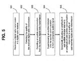
- step 501 the step of receiving a digital radio transmission in a digital radio receiver.
- step 501 the step of receiving a digital radio transmission in a digital radio receiver.
- This step includes steps known to those skilled in the art of radio design.
- step 502 the step of detecting the quality of the received digital radio transmission.
- the step of detecting the quality may be accomplished by way of detecting the RSSI, and/or by detecting one or more error counts provided by an ECC circuit.
- step 502 may be interchanged with step 503 described below.
- step 503 the step of decoding an audible communication from the received digital radio transmission. This step involves producing an audible baseband signal from the received digital RF signal. In one or more embodiments, step 503 may be interchanged with step 502 described above.
- step 504 the step of superimposing an audible indicator onto the audible communication, to form a composite audible signal.
- the type of audible indicator may include broadband noise, a single tone, a complex tone, and/or a buzz or the like.
- step 505 the step of dynamically adjusting an amplitude of the audible indicator relative to an amplitude of the audible communication responsive to a quality of the received digital audio transmission.
- the amplitude of the audible indicator may be adjusted inversely proportionally to the quality of the received digital audio transmission within at least a portion of the range in variation of quality - i.e., as the quality increases, the amplitude of the audible indicator decreases relative to the amplitude of the audible communication.
- the audible indicator may be turned off or adjusted to a substantially inaudible level if the quality of the received digital audio transmission exceeds a first predetermined level.
- the audible indicator may be turned off or adjusted to a substantially inaudible level if the quality of the received digital audio transmission does not exceed a second predetermined level. In this situation, the quality of the received digital audio transmission is so poor that the audible baseband signal of step 503 cannot be produced (i.e., the signal is lost) or is already corrupted or distorted because the capability of the ECC code has been exceeded. In another embodiment, the audible indicator may be turned off or adjusted to a substantially inaudible level if it is detected that the transmitting digital radio is actively transmitting a radio operator's conversation.
Landscapes
- Engineering & Computer Science (AREA)
- Computer Networks & Wireless Communication (AREA)
- Signal Processing (AREA)
- Physics & Mathematics (AREA)
- Electromagnetism (AREA)
- Mobile Radio Communication Systems (AREA)
- Detection And Prevention Of Errors In Transmission (AREA)
- Circuits Of Receivers In General (AREA)
- Telephone Function (AREA)
- Noise Elimination (AREA)
- Monitoring And Testing Of Transmission In General (AREA)
Claims (10)
- Verfahren zum Bereitstellen eines akustischen Indikators der Qualität einer empfangenen digitalen Funkübertragung, das die Schritte umfasst:- Empfangen einer digitalen Funkübertragung in einem digitalen Funkempfänger (210),- Bestimmen der Qualität der empfangenen digitalen Funkübertragung basierend auf einem Indikator der empfangenen Signalstärke und einer codierten Bitfehlerrate der empfangenen digitalen Funkübertragung,- Decodieren einer akustischen Kommunikation aus der empfangenen digitalen Funkübertragung, und- Hinzufügen eines ersten und/oder zweiten akustischen Indikators zu der akustischen Kommunikation, um ein zusammengesetztes akustisches Signal zu bilden, wobei der erste akustische Indikator in Antwort darauf hinzugefügt wird, dass der Indikator der empfangen Signalstärke unter einem ersten vorgegebenen Schwellenwert liegt, und wobei der zweite akustische Indikator in Antwort darauf hinzugefügt wird, dass die codierte Bitfehlerrate einen zweiten vorgegebenen Schwellenwert übersteigt,- wobei der erste akustische Indikator im Vergleich zum zweiten akustischen Indikator unterschiedlich ist.
- Verfahren nach Anspruch 1, wobei der Schritt des Hinzufügens ein Hinzufügen des zweiten akustischen Indikators nur dann umfasst, wenn die empfangene Signalstärke einen dritten vorgegebenen Schwellenwert übersteigt.
- Verfahren nach Anspruch 1, wobei der Indikator der empfangenen Signalstärke im digitalen Funkempfänger unter dem ersten Schwellenwert liegt, und der erste akustische Indikator in einem zweiten digitalen Funkempfänger auf eine akustische Kommunikation angewandt wird.
- Verfahren nach Anspruch 1, das ferner das selektive Deaktivieren des akustischen Indikators in Antwort auf eine Benutzereingabe in den digitalen Funkempfänger umfasst.
- Verfahren nach Anspruch 1, das ferner den Schritt umfasst:- Präsentieren eines Warnsignals für einen Benutzer des digitalen Funkempfängers, wobei das Warnsignal von der akustischen Kommunikation getrennt ist.
- Verfahren nach Anspruch 1, das ferner das Steuern der Amplitude des ersten akustischen Indikators basierend auf dem Indikator der empfangenen Signalstärke und das Steuern der Amplitude des zweiten akustischen Indikators basierend auf der codierten Bitfehlerrate umfasst.
- Vorrichtung (210) zum Bereitstellen eines akustischen Indikators der Qualität einer empfangenen digitalen Funkübertragung, die umfasst:- einen Detektor der Qualität der empfangenen digitalen Funkübertragung, der dafür konfiguriert ist, basierend auf einem Indikator der empfangenen Signalstärke und einer codierten Bitfehlerrate der empfangenen digitalen Funkübertragung die Qualität zu bestimmen,- einen Decodierer, der dafür konfiguriert ist, eine akustische Kommunikation aus der empfangenen digitalen Funkübertragung zu decodieren,- eine erste Signalquelle, die dafür konfiguriert ist, ein erstes akustisches Indikatorsignal zu bilden, um anzugeben, dass die empfangene digitale Funkübertragung eine erste vorgegebene Signalqualität hat,- eine zweite Signalquelle, die dafür konfiguriert ist, ein zweites akustisches Indikatorsignal zu bilden, um anzugeben, dass die empfangene digitale Funkübertragung eine zweite vorgegebene Signalqualität hat,- einen ersten Vergleicher, der dafür konfiguriert ist, den Indikator der empfangenen Signalstärke der empfangenen digitalen Funkübertragung mit einem ersten vorgegebenen Schwellenwert zu vergleichen,- einen zweiten Vergleicher, der dafür konfiguriert ist, die codierte Bitfehlerrate der empfangenen digitalen Funkübertragung mit einem zweiten vorgegebenen Schwellenwert zu vergleichen,- einen Kombinierer, der dafür konfiguriert ist, den ersten und/oder zweiten akustischen Indikator der akustischen Kommunikation hinzuzufügen, um ein zusammengesetztes akustisches Signal zu bilden,- wobei der erste akustische Indikator der akustischen Kommunikation nur dann hinzugefügt wird, wenn der Indikator der empfangen Signalstärke der empfangenen digitalen Funkübertragung unter dem ersten vorgegebenen Schwellenwert liegt, und der zweite akustische Indikator der akustischen Kommunikation nur dann hinzugefügt wird, wenn die codierte Bitfehlerrate der empfangenen digitalen Funkübertragung über dem zweiten vorgegebenen Schwellenwert liegt.
- Vorrichtung nach Anspruch 7, wobei der Kombinierer dafür konfiguriert ist, den zweiten akustischen Indikator nur dann hinzuzufügen, wenn der Indikator der empfangenen Signalstärke einen dritten vorgegebenen Schwellenwert übersteigt.
- Vorrichtung nach Anspruch 7, die ferner wenigstens einen Verstärker umfasst, der dafür konfiguriert ist, den ersten akustischen Indikator basierend auf dem Indikator der empfangenen Signalstärke und den zweiten akustischen Indikator basierend auf der codierten Bitfehlerrate zu verstärken.
- Verfahren zum Ermitteln einer Schmalbandinterferenz einer empfangenen digitalen Funkübertragung, das die Schritte umfasst:- Empfangen einer digitalen Funkübertragung in einem digitalen Funkempfänger (210),- Ermitteln eines Indikators der empfangenen Signalstärke der empfangenen digitalen Funkübertragung,- Ermitteln einer codierten Bitfehlerrate der empfangenen digitalen Funkübertragung,- Ermitteln eines Signalleistungsverlusts und Hinzufügen eines ersten akustischen Indikators zur digitalen Funkübertragung, wenn der Indikator der empfangenen Signalstärke unter einem ersten vorgegebenen Schwellenwert liegt,- Ermitteln einer Schmalbandinterferenz und Hinzufügen eines zweiten akustischen Indikators zur digitalen Funkübertragung, wenn der Indikator der empfangenen Signalstärke einen zweiten vorgegebenen Schwellenwert übersteigt und die codierte Bitfehlerrate einen dritten vorgegebenen Schwellenwert übersteigt.
Applications Claiming Priority (2)
| Application Number | Priority Date | Filing Date | Title |
|---|---|---|---|
| US12/757,353 US8600325B2 (en) | 2010-04-09 | 2010-04-09 | Simulated degradation of SNR in decoded digital audio correlated to wireless link bit-error rate |
| PCT/US2011/028582 WO2011126685A1 (en) | 2010-04-09 | 2011-03-16 | Simulated degradation of snr in decoded digital audio correlated to wireless link bit-error rate |
Publications (2)
| Publication Number | Publication Date |
|---|---|
| EP2556593A1 EP2556593A1 (de) | 2013-02-13 |
| EP2556593B1 true EP2556593B1 (de) | 2014-05-21 |
Family
ID=44059048
Family Applications (1)
| Application Number | Title | Priority Date | Filing Date |
|---|---|---|---|
| EP11710962.9A Active EP2556593B1 (de) | 2010-04-09 | 2011-03-16 | Simulierter snr-verlust bei decodiertem digitalem audio im zusammenhang mit der bitfehlerrate einer drahtlosverbindung |
Country Status (9)
| Country | Link |
|---|---|
| US (1) | US8600325B2 (de) |
| EP (1) | EP2556593B1 (de) |
| JP (1) | JP5665965B2 (de) |
| KR (1) | KR101415416B1 (de) |
| CN (1) | CN102884728B (de) |
| AU (1) | AU2011238774B2 (de) |
| CA (1) | CA2794736C (de) |
| RU (1) | RU2524564C2 (de) |
| WO (1) | WO2011126685A1 (de) |
Cited By (1)
| Publication number | Priority date | Publication date | Assignee | Title |
|---|---|---|---|---|
| EP4468630A1 (de) * | 2023-05-19 | 2024-11-27 | Honeywell International Inc. | System und verfahren zur erkennung und meldung von funkkommunikationsanomalien |
Families Citing this family (2)
| Publication number | Priority date | Publication date | Assignee | Title |
|---|---|---|---|---|
| US9916835B2 (en) * | 2015-01-22 | 2018-03-13 | Sennheiser Electronic Gmbh & Co. Kg | Digital wireless audio transmission system |
| CN120496548A (zh) * | 2025-04-25 | 2025-08-15 | 新维陆科技(珠海)有限公司 | 振动波处理方法、装置、存储介质 |
Family Cites Families (10)
| Publication number | Priority date | Publication date | Assignee | Title |
|---|---|---|---|---|
| JP2848143B2 (ja) * | 1992-08-04 | 1999-01-20 | 日本電気株式会社 | 無線電話機 |
| JPH06232806A (ja) * | 1993-02-01 | 1994-08-19 | Hitachi Ltd | ディジタル移動通信端末 |
| US5991901A (en) | 1993-02-11 | 1999-11-23 | Motorola, Inc. | Indication of coverage area limits within digital communication systems |
| SE502244C2 (sv) * | 1993-06-11 | 1995-09-25 | Ericsson Telefon Ab L M | Sätt och anordning för avkodning av ljudsignaler i ett system för mobilradiokommunikation |
| JP2922414B2 (ja) * | 1994-02-17 | 1999-07-26 | 三菱電機株式会社 | 無線電話移動機 |
| US5809414A (en) | 1995-11-22 | 1998-09-15 | Northern Telecom Limited | User out-of-range indication for digital wireless systems |
| EP0895678A2 (de) | 1996-03-12 | 1999-02-10 | Ericsson Inc. | Verfahren und vorrichtung zur antennenausrichtung in einem mobilen funktelefon durch einwurf eines audiosignals |
| US6243568B1 (en) | 1997-03-22 | 2001-06-05 | Sharp Laboratories Of America, Inc. | System and method for intuitively indicating signal quality in a wireless digital communications network |
| JP3780530B2 (ja) | 1997-06-16 | 2006-05-31 | 松下電器産業株式会社 | 電気二重層キャパシタ及びその製造方法 |
| GB2396527B (en) | 2002-12-20 | 2005-03-16 | Motorola Inc | Systems and methods for reducing interference |
-
2010
- 2010-04-09 US US12/757,353 patent/US8600325B2/en not_active Expired - Fee Related
-
2011
- 2011-03-16 AU AU2011238774A patent/AU2011238774B2/en active Active
- 2011-03-16 EP EP11710962.9A patent/EP2556593B1/de active Active
- 2011-03-16 CN CN201180022860.XA patent/CN102884728B/zh not_active Expired - Fee Related
- 2011-03-16 JP JP2013502616A patent/JP5665965B2/ja not_active Expired - Fee Related
- 2011-03-16 RU RU2012144261/08A patent/RU2524564C2/ru not_active IP Right Cessation
- 2011-03-16 CA CA2794736A patent/CA2794736C/en active Active
- 2011-03-16 WO PCT/US2011/028582 patent/WO2011126685A1/en not_active Ceased
- 2011-03-16 KR KR1020127028833A patent/KR101415416B1/ko not_active Expired - Fee Related
Cited By (1)
| Publication number | Priority date | Publication date | Assignee | Title |
|---|---|---|---|---|
| EP4468630A1 (de) * | 2023-05-19 | 2024-11-27 | Honeywell International Inc. | System und verfahren zur erkennung und meldung von funkkommunikationsanomalien |
Also Published As
| Publication number | Publication date |
|---|---|
| JP2013524629A (ja) | 2013-06-17 |
| CN102884728B (zh) | 2015-01-28 |
| AU2011238774A1 (en) | 2012-10-25 |
| KR20120138245A (ko) | 2012-12-24 |
| US20110250851A1 (en) | 2011-10-13 |
| RU2524564C2 (ru) | 2014-07-27 |
| KR101415416B1 (ko) | 2014-07-04 |
| US8600325B2 (en) | 2013-12-03 |
| CN102884728A (zh) | 2013-01-16 |
| RU2012144261A (ru) | 2014-05-20 |
| EP2556593A1 (de) | 2013-02-13 |
| CA2794736A1 (en) | 2011-10-13 |
| JP5665965B2 (ja) | 2015-02-04 |
| WO2011126685A1 (en) | 2011-10-13 |
| AU2011238774B2 (en) | 2014-03-06 |
| CA2794736C (en) | 2014-05-13 |
Similar Documents
| Publication | Publication Date | Title |
|---|---|---|
| US4893349A (en) | FM communication system with improved response to rayleigh-faded received signals | |
| JP4370621B2 (ja) | 通信端末装置、通信制御方法および通信制御プログラム | |
| US7203471B2 (en) | System and method for selectively utilizing an attenuation device in a two-way radio receiver based on squelch detect and radio signal strength indication (RSSI) | |
| KR101130110B1 (ko) | 에프엠 수신기의 오디오 노이즈 제거방법 및 장치 | |
| CA2794736C (en) | Simulated degradation of snr in decoded digital audio correlated to wireless link bit-error rate | |
| US9119004B2 (en) | Wireless device | |
| JP2011055058A (ja) | インターホンシステム | |
| US6466905B1 (en) | Differentiation of error conditions in digital voice communication systems | |
| US20030194980A1 (en) | Method and apparatus for indicating low signal quality in a digitized audio environment | |
| US10789970B2 (en) | Receiving device and receiving method | |
| CN111697982B (zh) | 一种自适应噪声处理方法、装置、系统及存储介质 | |
| JP5885571B2 (ja) | ディジタル放送の受信装置 | |
| EP0380475A4 (en) | Fm communications system with improved response to rayleigh-faded received signals | |
| JP4795057B2 (ja) | 受信装置 | |
| JP2006100891A (ja) | 無線機 | |
| CA1275447C (en) | Fm communication system with improved response to rayleigh-faded received signals | |
| JP2009303050A (ja) | ワイヤレスイヤホン | |
| CN119586014A (zh) | 用于发现无线电通信网络和过滤音频信号以允许群组通信的方法 | |
| WO2009113226A1 (ja) | 無線受信装置 | |
| JP2001008257A (ja) | 移動無線端末装置 | |
| JPH06232806A (ja) | ディジタル移動通信端末 | |
| JP5668657B2 (ja) | デジタル無線受信機 | |
| JP2009182594A (ja) | インターホンシステム | |
| JP2018056858A (ja) | 音声無線通信装置 |
Legal Events
| Date | Code | Title | Description |
|---|---|---|---|
| PUAI | Public reference made under article 153(3) epc to a published international application that has entered the european phase |
Free format text: ORIGINAL CODE: 0009012 |
|
| 17P | Request for examination filed |
Effective date: 20121029 |
|
| AK | Designated contracting states |
Kind code of ref document: A1 Designated state(s): AL AT BE BG CH CY CZ DE DK EE ES FI FR GB GR HR HU IE IS IT LI LT LU LV MC MK MT NL NO PL PT RO RS SE SI SK SM TR |
|
| DAX | Request for extension of the european patent (deleted) | ||
| GRAP | Despatch of communication of intention to grant a patent |
Free format text: ORIGINAL CODE: EPIDOSNIGR1 |
|
| INTG | Intention to grant announced |
Effective date: 20140107 |
|
| GRAS | Grant fee paid |
Free format text: ORIGINAL CODE: EPIDOSNIGR3 |
|
| GRAA | (expected) grant |
Free format text: ORIGINAL CODE: 0009210 |
|
| AK | Designated contracting states |
Kind code of ref document: B1 Designated state(s): AL AT BE BG CH CY CZ DE DK EE ES FI FR GB GR HR HU IE IS IT LI LT LU LV MC MK MT NL NO PL PT RO RS SE SI SK SM TR |
|
| REG | Reference to a national code |
Ref country code: GB Ref legal event code: FG4D |
|
| REG | Reference to a national code |
Ref country code: CH Ref legal event code: EP |
|
| REG | Reference to a national code |
Ref country code: AT Ref legal event code: REF Ref document number: 670037 Country of ref document: AT Kind code of ref document: T Effective date: 20140615 |
|
| REG | Reference to a national code |
Ref country code: IE Ref legal event code: FG4D |
|
| REG | Reference to a national code |
Ref country code: DE Ref legal event code: R096 Ref document number: 602011007209 Country of ref document: DE Effective date: 20140703 |
|
| REG | Reference to a national code |
Ref country code: NL Ref legal event code: VDEP Effective date: 20140521 Ref country code: AT Ref legal event code: MK05 Ref document number: 670037 Country of ref document: AT Kind code of ref document: T Effective date: 20140521 |
|
| REG | Reference to a national code |
Ref country code: LT Ref legal event code: MG4D |
|
| PG25 | Lapsed in a contracting state [announced via postgrant information from national office to epo] |
Ref country code: LT Free format text: LAPSE BECAUSE OF FAILURE TO SUBMIT A TRANSLATION OF THE DESCRIPTION OR TO PAY THE FEE WITHIN THE PRESCRIBED TIME-LIMIT Effective date: 20140521 Ref country code: GR Free format text: LAPSE BECAUSE OF FAILURE TO SUBMIT A TRANSLATION OF THE DESCRIPTION OR TO PAY THE FEE WITHIN THE PRESCRIBED TIME-LIMIT Effective date: 20140822 Ref country code: IS Free format text: LAPSE BECAUSE OF FAILURE TO SUBMIT A TRANSLATION OF THE DESCRIPTION OR TO PAY THE FEE WITHIN THE PRESCRIBED TIME-LIMIT Effective date: 20140921 Ref country code: FI Free format text: LAPSE BECAUSE OF FAILURE TO SUBMIT A TRANSLATION OF THE DESCRIPTION OR TO PAY THE FEE WITHIN THE PRESCRIBED TIME-LIMIT Effective date: 20140521 Ref country code: NO Free format text: LAPSE BECAUSE OF FAILURE TO SUBMIT A TRANSLATION OF THE DESCRIPTION OR TO PAY THE FEE WITHIN THE PRESCRIBED TIME-LIMIT Effective date: 20140821 |
|
| PG25 | Lapsed in a contracting state [announced via postgrant information from national office to epo] |
Ref country code: SE Free format text: LAPSE BECAUSE OF FAILURE TO SUBMIT A TRANSLATION OF THE DESCRIPTION OR TO PAY THE FEE WITHIN THE PRESCRIBED TIME-LIMIT Effective date: 20140521 Ref country code: AT Free format text: LAPSE BECAUSE OF FAILURE TO SUBMIT A TRANSLATION OF THE DESCRIPTION OR TO PAY THE FEE WITHIN THE PRESCRIBED TIME-LIMIT Effective date: 20140521 Ref country code: LV Free format text: LAPSE BECAUSE OF FAILURE TO SUBMIT A TRANSLATION OF THE DESCRIPTION OR TO PAY THE FEE WITHIN THE PRESCRIBED TIME-LIMIT Effective date: 20140521 Ref country code: PL Free format text: LAPSE BECAUSE OF FAILURE TO SUBMIT A TRANSLATION OF THE DESCRIPTION OR TO PAY THE FEE WITHIN THE PRESCRIBED TIME-LIMIT Effective date: 20140521 Ref country code: RS Free format text: LAPSE BECAUSE OF FAILURE TO SUBMIT A TRANSLATION OF THE DESCRIPTION OR TO PAY THE FEE WITHIN THE PRESCRIBED TIME-LIMIT Effective date: 20140521 Ref country code: ES Free format text: LAPSE BECAUSE OF FAILURE TO SUBMIT A TRANSLATION OF THE DESCRIPTION OR TO PAY THE FEE WITHIN THE PRESCRIBED TIME-LIMIT Effective date: 20140521 Ref country code: HR Free format text: LAPSE BECAUSE OF FAILURE TO SUBMIT A TRANSLATION OF THE DESCRIPTION OR TO PAY THE FEE WITHIN THE PRESCRIBED TIME-LIMIT Effective date: 20140521 |
|
| PG25 | Lapsed in a contracting state [announced via postgrant information from national office to epo] |
Ref country code: PT Free format text: LAPSE BECAUSE OF FAILURE TO SUBMIT A TRANSLATION OF THE DESCRIPTION OR TO PAY THE FEE WITHIN THE PRESCRIBED TIME-LIMIT Effective date: 20140922 |
|
| PG25 | Lapsed in a contracting state [announced via postgrant information from national office to epo] |
Ref country code: EE Free format text: LAPSE BECAUSE OF FAILURE TO SUBMIT A TRANSLATION OF THE DESCRIPTION OR TO PAY THE FEE WITHIN THE PRESCRIBED TIME-LIMIT Effective date: 20140521 Ref country code: RO Free format text: LAPSE BECAUSE OF FAILURE TO SUBMIT A TRANSLATION OF THE DESCRIPTION OR TO PAY THE FEE WITHIN THE PRESCRIBED TIME-LIMIT Effective date: 20140521 Ref country code: BE Free format text: LAPSE BECAUSE OF FAILURE TO SUBMIT A TRANSLATION OF THE DESCRIPTION OR TO PAY THE FEE WITHIN THE PRESCRIBED TIME-LIMIT Effective date: 20140521 Ref country code: CZ Free format text: LAPSE BECAUSE OF FAILURE TO SUBMIT A TRANSLATION OF THE DESCRIPTION OR TO PAY THE FEE WITHIN THE PRESCRIBED TIME-LIMIT Effective date: 20140521 Ref country code: DK Free format text: LAPSE BECAUSE OF FAILURE TO SUBMIT A TRANSLATION OF THE DESCRIPTION OR TO PAY THE FEE WITHIN THE PRESCRIBED TIME-LIMIT Effective date: 20140521 Ref country code: SK Free format text: LAPSE BECAUSE OF FAILURE TO SUBMIT A TRANSLATION OF THE DESCRIPTION OR TO PAY THE FEE WITHIN THE PRESCRIBED TIME-LIMIT Effective date: 20140521 |
|
| REG | Reference to a national code |
Ref country code: DE Ref legal event code: R097 Ref document number: 602011007209 Country of ref document: DE |
|
| PG25 | Lapsed in a contracting state [announced via postgrant information from national office to epo] |
Ref country code: NL Free format text: LAPSE BECAUSE OF FAILURE TO SUBMIT A TRANSLATION OF THE DESCRIPTION OR TO PAY THE FEE WITHIN THE PRESCRIBED TIME-LIMIT Effective date: 20140521 |
|
| PLBE | No opposition filed within time limit |
Free format text: ORIGINAL CODE: 0009261 |
|
| STAA | Information on the status of an ep patent application or granted ep patent |
Free format text: STATUS: NO OPPOSITION FILED WITHIN TIME LIMIT |
|
| 26N | No opposition filed |
Effective date: 20150224 |
|
| PG25 | Lapsed in a contracting state [announced via postgrant information from national office to epo] |
Ref country code: IT Free format text: LAPSE BECAUSE OF FAILURE TO SUBMIT A TRANSLATION OF THE DESCRIPTION OR TO PAY THE FEE WITHIN THE PRESCRIBED TIME-LIMIT Effective date: 20140521 |
|
| REG | Reference to a national code |
Ref country code: DE Ref legal event code: R097 Ref document number: 602011007209 Country of ref document: DE Effective date: 20150224 |
|
| PG25 | Lapsed in a contracting state [announced via postgrant information from national office to epo] |
Ref country code: SI Free format text: LAPSE BECAUSE OF FAILURE TO SUBMIT A TRANSLATION OF THE DESCRIPTION OR TO PAY THE FEE WITHIN THE PRESCRIBED TIME-LIMIT Effective date: 20140521 |
|
| PG25 | Lapsed in a contracting state [announced via postgrant information from national office to epo] |
Ref country code: MC Free format text: LAPSE BECAUSE OF FAILURE TO SUBMIT A TRANSLATION OF THE DESCRIPTION OR TO PAY THE FEE WITHIN THE PRESCRIBED TIME-LIMIT Effective date: 20140521 Ref country code: LU Free format text: LAPSE BECAUSE OF FAILURE TO SUBMIT A TRANSLATION OF THE DESCRIPTION OR TO PAY THE FEE WITHIN THE PRESCRIBED TIME-LIMIT Effective date: 20150316 |
|
| REG | Reference to a national code |
Ref country code: CH Ref legal event code: PL |
|
| REG | Reference to a national code |
Ref country code: IE Ref legal event code: MM4A |
|
| PG25 | Lapsed in a contracting state [announced via postgrant information from national office to epo] |
Ref country code: IE Free format text: LAPSE BECAUSE OF NON-PAYMENT OF DUE FEES Effective date: 20150316 Ref country code: CH Free format text: LAPSE BECAUSE OF NON-PAYMENT OF DUE FEES Effective date: 20150331 Ref country code: LI Free format text: LAPSE BECAUSE OF NON-PAYMENT OF DUE FEES Effective date: 20150331 |
|
| REG | Reference to a national code |
Ref country code: FR Ref legal event code: PLFP Year of fee payment: 6 |
|
| PG25 | Lapsed in a contracting state [announced via postgrant information from national office to epo] |
Ref country code: MT Free format text: LAPSE BECAUSE OF FAILURE TO SUBMIT A TRANSLATION OF THE DESCRIPTION OR TO PAY THE FEE WITHIN THE PRESCRIBED TIME-LIMIT Effective date: 20140521 |
|
| REG | Reference to a national code |
Ref country code: FR Ref legal event code: PLFP Year of fee payment: 7 |
|
| PG25 | Lapsed in a contracting state [announced via postgrant information from national office to epo] |
Ref country code: HU Free format text: LAPSE BECAUSE OF FAILURE TO SUBMIT A TRANSLATION OF THE DESCRIPTION OR TO PAY THE FEE WITHIN THE PRESCRIBED TIME-LIMIT; INVALID AB INITIO Effective date: 20110316 Ref country code: SM Free format text: LAPSE BECAUSE OF FAILURE TO SUBMIT A TRANSLATION OF THE DESCRIPTION OR TO PAY THE FEE WITHIN THE PRESCRIBED TIME-LIMIT Effective date: 20140521 Ref country code: BG Free format text: LAPSE BECAUSE OF FAILURE TO SUBMIT A TRANSLATION OF THE DESCRIPTION OR TO PAY THE FEE WITHIN THE PRESCRIBED TIME-LIMIT Effective date: 20140521 |
|
| PG25 | Lapsed in a contracting state [announced via postgrant information from national office to epo] |
Ref country code: CY Free format text: LAPSE BECAUSE OF FAILURE TO SUBMIT A TRANSLATION OF THE DESCRIPTION OR TO PAY THE FEE WITHIN THE PRESCRIBED TIME-LIMIT Effective date: 20140521 |
|
| PG25 | Lapsed in a contracting state [announced via postgrant information from national office to epo] |
Ref country code: TR Free format text: LAPSE BECAUSE OF FAILURE TO SUBMIT A TRANSLATION OF THE DESCRIPTION OR TO PAY THE FEE WITHIN THE PRESCRIBED TIME-LIMIT Effective date: 20140521 |
|
| REG | Reference to a national code |
Ref country code: FR Ref legal event code: PLFP Year of fee payment: 8 |
|
| PG25 | Lapsed in a contracting state [announced via postgrant information from national office to epo] |
Ref country code: MK Free format text: LAPSE BECAUSE OF FAILURE TO SUBMIT A TRANSLATION OF THE DESCRIPTION OR TO PAY THE FEE WITHIN THE PRESCRIBED TIME-LIMIT Effective date: 20140521 |
|
| PG25 | Lapsed in a contracting state [announced via postgrant information from national office to epo] |
Ref country code: AL Free format text: LAPSE BECAUSE OF FAILURE TO SUBMIT A TRANSLATION OF THE DESCRIPTION OR TO PAY THE FEE WITHIN THE PRESCRIBED TIME-LIMIT Effective date: 20140521 |
|
| REG | Reference to a national code |
Ref country code: DE Ref legal event code: R081 Ref document number: 602011007209 Country of ref document: DE Owner name: L3HARRIS TECHNOLOGIES, INC. (N.D.GES.D.STAATES, US Free format text: FORMER OWNER: HARRIS CORP., MELBOURNE, FLA., US |
|
| P01 | Opt-out of the competence of the unified patent court (upc) registered |
Effective date: 20230530 |
|
| PGFP | Annual fee paid to national office [announced via postgrant information from national office to epo] |
Ref country code: GB Payment date: 20260327 Year of fee payment: 16 |
|
| PGFP | Annual fee paid to national office [announced via postgrant information from national office to epo] |
Ref country code: DE Payment date: 20260327 Year of fee payment: 16 |
|
| PGFP | Annual fee paid to national office [announced via postgrant information from national office to epo] |
Ref country code: FR Payment date: 20260325 Year of fee payment: 16 |