EP2554831A1 - Starter system - Google Patents
Starter system Download PDFInfo
- Publication number
- EP2554831A1 EP2554831A1 EP11765454A EP11765454A EP2554831A1 EP 2554831 A1 EP2554831 A1 EP 2554831A1 EP 11765454 A EP11765454 A EP 11765454A EP 11765454 A EP11765454 A EP 11765454A EP 2554831 A1 EP2554831 A1 EP 2554831A1
- Authority
- EP
- European Patent Office
- Prior art keywords
- pinion
- ring gear
- engine
- rotation speed
- motor
- Prior art date
- Legal status (The legal status is an assumption and is not a legal conclusion. Google has not performed a legal analysis and makes no representation as to the accuracy of the status listed.)
- Withdrawn
Links
Images


Classifications
-
- F—MECHANICAL ENGINEERING; LIGHTING; HEATING; WEAPONS; BLASTING
- F02—COMBUSTION ENGINES; HOT-GAS OR COMBUSTION-PRODUCT ENGINE PLANTS
- F02N—STARTING OF COMBUSTION ENGINES; STARTING AIDS FOR SUCH ENGINES, NOT OTHERWISE PROVIDED FOR
- F02N11/00—Starting of engines by means of electric motors
- F02N11/08—Circuits or control means specially adapted for starting of engines
- F02N11/0814—Circuits or control means specially adapted for starting of engines comprising means for controlling automatic idle-start-stop
- F02N11/0844—Circuits or control means specially adapted for starting of engines comprising means for controlling automatic idle-start-stop with means for restarting the engine directly after an engine stop request, e.g. caused by change of driver mind
-
- F—MECHANICAL ENGINEERING; LIGHTING; HEATING; WEAPONS; BLASTING
- F02—COMBUSTION ENGINES; HOT-GAS OR COMBUSTION-PRODUCT ENGINE PLANTS
- F02N—STARTING OF COMBUSTION ENGINES; STARTING AIDS FOR SUCH ENGINES, NOT OTHERWISE PROVIDED FOR
- F02N11/00—Starting of engines by means of electric motors
- F02N11/08—Circuits or control means specially adapted for starting of engines
- F02N11/0851—Circuits or control means specially adapted for starting of engines characterised by means for controlling the engagement or disengagement between engine and starter, e.g. meshing of pinion and engine gear
- F02N11/0855—Circuits or control means specially adapted for starting of engines characterised by means for controlling the engagement or disengagement between engine and starter, e.g. meshing of pinion and engine gear during engine shutdown or after engine stop before start command, e.g. pre-engagement of pinion
-
- F—MECHANICAL ENGINEERING; LIGHTING; HEATING; WEAPONS; BLASTING
- F02—COMBUSTION ENGINES; HOT-GAS OR COMBUSTION-PRODUCT ENGINE PLANTS
- F02N—STARTING OF COMBUSTION ENGINES; STARTING AIDS FOR SUCH ENGINES, NOT OTHERWISE PROVIDED FOR
- F02N15/00—Other power-operated starting apparatus; Component parts, details, or accessories, not provided for in, or of interest apart from groups F02N5/00 - F02N13/00
- F02N15/02—Gearing between starting-engines and started engines; Engagement or disengagement thereof
-
- F—MECHANICAL ENGINEERING; LIGHTING; HEATING; WEAPONS; BLASTING
- F02—COMBUSTION ENGINES; HOT-GAS OR COMBUSTION-PRODUCT ENGINE PLANTS
- F02N—STARTING OF COMBUSTION ENGINES; STARTING AIDS FOR SUCH ENGINES, NOT OTHERWISE PROVIDED FOR
- F02N2200/00—Parameters used for control of starting apparatus
- F02N2200/04—Parameters used for control of starting apparatus said parameters being related to the starter motor
- F02N2200/041—Starter speed
-
- Y—GENERAL TAGGING OF NEW TECHNOLOGICAL DEVELOPMENTS; GENERAL TAGGING OF CROSS-SECTIONAL TECHNOLOGIES SPANNING OVER SEVERAL SECTIONS OF THE IPC; TECHNICAL SUBJECTS COVERED BY FORMER USPC CROSS-REFERENCE ART COLLECTIONS [XRACs] AND DIGESTS
- Y02—TECHNOLOGIES OR APPLICATIONS FOR MITIGATION OR ADAPTATION AGAINST CLIMATE CHANGE
- Y02T—CLIMATE CHANGE MITIGATION TECHNOLOGIES RELATED TO TRANSPORTATION
- Y02T10/00—Road transport of goods or passengers
- Y02T10/10—Internal combustion engine [ICE] based vehicles
- Y02T10/40—Engine management systems
Definitions
- the present invention relates to a starter system for idling stop.
- An object of the invention is to provide a starter system capable of rapidly restarting an engine in response to a restart request on the way to an engine stop without generating noise.
- a starter system provided according to the preferred mode of the invention includes a pinion which transmits power for starting an engine to a ring gear connected with the engine; a motor which rotates the pinion; a magnet switch which pushes the pinion out toward the ring gear; a one-way clutch which prevents transmission of the power of the motor in the reverse rotation direction of the pinion; and a controller which controls the motor and the magnet switch.
- the controller controls the magnet switch such that the magnet switch meshes the pinion with the ring gear when the following conditions are satisfied after an engine stop: (1) both the rotation direction of the ring gear and the rotation direction of the pinion are normal directions; and (2) when a first rotation speed of the ring gear is higher than a second rotation speed synchronous with the rotation speed of the pinion.
- a starter system capable of rapidly restarting an engine in response to a restart request issued on the way to an engine stop without generating noise can be provided.
- a starter system according to this embodiment is hereinafter described with reference to FIGS. 1 through 7 .
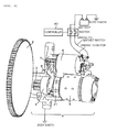
- FIG. 6 illustrates a relationship between a starter and a ring gear.
- a ring gear 2 is directly connected with a crank shaft of an engine so that the rotation of the ring gear 2 and the rotation of the engine can be combined.
- the figure shows only a simplified shape of the ring gear.
- a starter 1 attached to the outside wall of the engine starts the engine by rotating a pinion 3 meshed with the ring gear 2.
- the power for rotating the pinion 3 is generated by a motor 5. This power is transmitted to the pinion with sufficient torque raised by reduction of the revolutions of the output shaft of the motor by the function of a reduction mechanism 21.
- a one-way clutch 4 is provided between the motor 5 and the pinion 3.
- the one-way clutch 4 is so designed as to transmit the power only in the direction from the motor 5 to the engine.
- the rotation speed of the ring gear 2 under the condition of engagement between the pinion 3 and the ring gear 2 becomes the synchronous speed with the rotation speed of the motor 5 in correspondence with the reduction ratio, or a speed higher than the synchronous speed. More specifically, when the rotation speed of the ring gear 2 comes to drop to a speed lower than the synchronous speed with the rotation speed of the motor 5, the one-way clutch 4 transmits power to the ring gear 2.
- the rotation speed of the ring gear 2 does not become lower than the synchronous speed with the rotation speed of the motor 5.
- the synchronous speed in this context is a rotation speed which allows rotations of the pinion and the ring gear in engagement with each other.
- the power for plunging the pinion 3 into the ring gear 2 is generated by a magnet switch 6.
- the magnet switch 6 contains an electromagnet which attracts a plunger 7 located at the center of the magnet switch 6 by using an electromagnetic force so as to allow linear movement of the plunger 7.
- the magnet switch 6 contains a spring which pushes the plunger 7 outward at the time of cancellation of energization. This movement of the plunger 7 is transmitted to the pinion 3 via the shift lever 8, whereby the pinion is drawn inward for disengagement from the ring gear.
- the motor 5 and the magnet switch 6 are controlled by a controller 20.
- the controller 20 may be either an engine control unit (ECU) or a separate controller dedicated for control of the starter 1. While FIG. 6 shows an example of the controller 20 disposed separately from the starter 1, the controller 20 and the starter 1 may be an integrated unit when the controller 20 is a separate controller dedicated for control of the starter 1.
- ECU engine control unit
- FIG. 6 shows an example of the controller 20 disposed separately from the starter 1
- the controller 20 and the starter 1 may be an integrated unit when the controller 20 is a separate controller dedicated for control of the starter 1.
- the controller 20 pushes the pinion 3 out toward the ring gear 2 regardless of the presence or absence of an engine restart request from the driver.
- the controller 20 pushes the pinion 3 out toward the ring gear 2 regardless of the presence or absence of an engine restart request from the driver.
- the engine can restart immediately.
- the vehicle can stop right away at the moment of no load of the engine or a sufficiently low load of the engine. In this case, a certain period for confirming that an immediate restart request is not issued is unnecessary. Accordingly, the period of the engine stop increases, which reduces both the fuel cost and the carbon dioxide exhaust amount.
- the controller 20 controls the magnet switch 6 such that the pinion 3 can be pushed out toward the ring gear 2 during inertial rotation of the motor 5 effected by temporarily rotating the motor 5 and then suspending the supply of the power for rotating the motor 5 in the period of inertial rotation of the engine after the engine stop.
- FIG. 7 shows the relationship between the plunge timing of the pinion 3 and the rotation speed of the engine.
- the horizontal axis represents time, whereas the vertical axis represents the rotation speed.
- the rotation speed of the engine indicated by a solid line shows an example of actual values measured at the time of a simple engine stop.
- the rotation speed of the engine is equivalent to the rotation speed of the ring gear 2.
- the rotation speed of the pinion 3 converted into the synchronous rotation speed of the ring gear 2 is indicated by a broken line so as to show the timing of engagement of the pinion 3.
- the controller 20 energizes the magnet switch 6 at the time of an arrow 101 to allow plunge of the pinion. As a result, the pinion 3 contacts the ring gear 2 at the time of an arrow 102.
- a certain time is required before contact between the pinion 3 and the ring gear 2 for acceleration of the movable portions of the pinion 3 and the like and shift thereof through the clearance between the ring gear 2 and the pinion 3.
- a time difference is produced between the timing 101 for energization of the magnet switch 6 and the timing 102 for contact between the pinion 3 and the ring gear 2.
- the rotation speed of the engine continuously changes during the period of this time difference, whereby a rotation speed difference indicated by a width 103 is produced between the ring gear and the pinion at the time of the timing 102 for contact.
- the controller 20 controls plunge of the pinion 3 such that the rotation speed of the ring gear 2 at the moment of contact between the pinion 3 and the ring gear 2 produced by the plunge of the pinion 3 becomes higher than the rotation speed synchronous with the rotation speed of the pinion 3.
- the appropriate timing is such a timing which produces a speed difference larger than 0 revolution per minute and smaller than 80 revolutions per minute.
- the pinion 3 After the contact between the pinion 3 and the ring gear 2, the pinion 3 is inserted at the time when the teeth of the pinion come into the clearances between the teeth of the ring gear 2. As a result, the ring gear 2 and the pinion 3 engage with each other and rotate in synchronization with each other.
- the rotation speed of the ring gear 2 at that time is higher than the speed synchronous with the motor 5, the ring gear 2 rotates without synchronization by the function of the one-way clutch 4. In this case, the ring gear 2 comes to rotate in synchronization with the motor 5 after the rotation speed of the ring gear 2 is reduced to a rotation speed synchronous with the motor 5.
- the gear ratio becomes 10.
- the controller 20 controls such that the pinion 3 can be pushed out at the time when the rotation speed of the ring gear 2 becomes higher than 100rpm.
- the present inventors have found from their studies that the rotation speed of the ring gear 2 may drop approximately up to 130rpm during the period from the moment of the start of push-out of the pinion 3 to the moment of contact between the pinion 3 and the ring gear 2.
- the controller 20 determines the contact timing between the pinion 3 and the ring gear 2 while calculating the rotation speed drop during this period.
- the gear ratio is defined as (the tooth number of the ring gear 2) / (the tooth number of the pinion 3).
- (the number of revolutions of the ring gear 2) is larger than (the number of revolutions of the pinion 3) / (the gear ratio)
- it is defined that the rotation speed of the ring gear 2 is higher than the rotation speed synchronous with the rotation speed of the pinion 3.
- This embodiment is characterized in the point that, with the one-way clutch 4 provided within the starter 1, the pinion 3 is pushed out toward the ring gear 2 at the moment when the rotation speed of the ring gear 2 becomes higher than the rotation speed synchronous with the rotation speed of the pinion 3.
- This structure eliminates the necessity for synchronization between the motor and the ring gear after engagement between the ring gear 2 and the pinion 3, and avoids impact caused by connection between rotational bodies having different speed differences. Accordingly, generation of noise stops.
- the gear is difficult to insert by any pushing force under the condition of contact between the side surfaces of both the gears.
- the clearances (backlash) between the respective teeth engaging with each other are not allowed to be widened.
- the possibility of complete mesh of the teeth of the pinion 3 into the clearances between the teeth of the ring gear 2 is extremely low, while the possibility of contact between the side surfaces of the teeth of the ring gear 2 and the pinion 3 is extremely high.
- the action of the engine shown in FIG. 7 shows the case in which the pinion is not meshed.
- the change of the rotation speed of the engine varies after the engagement of the pinion 3. While the example in which the pinion is rotated prior to engagement of the pinion 3 has been discussed in this embodiment, the rotation speed of the pinion may be set to zero.
- FIG. 1 is a front view of the pinion 3 and the ring gear 2.
- the plunge of the pinion 3 is achieved by its movement from the rear side toward the front side with respect to the sheet surface of the figure.
- the rotation direction of the normal rotation of the pinion 3 is indicated by an arrow 9, while the rotation direction of the normal rotation of the ring gear engaging with the pinion 3 is indicated by an arrow 10.
- Chamfers 12 formed on the pinion 3 in the advancing direction of the normal rotation of the pinion 3 are effective at the time of engagement of the pinion on the way to the engine stop.
- Chamfers 13 formed on the opposite side with respect to the advancing direction of the pinion 3 are effective at the initial engine start, and useful at the time of engagement of the rotating pinion 3 with the ring gear 2 remaining stationary.
- the chamfers 13 may be eliminated in such a structure which always permits engagement of the pinion 3 at the time of a stop of the engine.
- Chamfers 14 and 15 formed on the ring gear 2 on the rear side of the sheet surface are invisible and therefore indicated by broken lines as invisible lines.
- the chamfers 15 formed on the opposite side with respect to the advancing direction of the normal rotation of the ring gear 2 are effective at the time of engagement of the pinion 3 on the way to the engine stop.
- the chamfers 14 formed in the advancing direction of the ring gear 2 are effective at the initial start of the engine.
- the chamfers 12 and the chamfers 15 have the same function, and similarly the chamfers 13 and the chamfers 14 have the same function. It is preferable that chamfers in the uniform shape are formed on all the teeth of the pinion 3, and that chamfers in the uniform shape are formed on all the teeth of the ring gear 2.
- a maximum width 17 corresponds to the maximum width of each of the chamfers 12 as viewed in the direction perpendicular to a side surface 18 of the pinion.
- the present inventors have found from their studies that the dimension of the maximum width 17 set larger than 1/10 of a tooth thickness 16 and smaller than 1/2 of the tooth thickness is particularly effective for reduction of the decrease in the tooth width of the pinion, reduction of increase in the surface pressure produced on the tooth surface at the time of transmission of power, and maintenance of sufficient durability.
- the tooth thickness in this context refers to a distance such as the tooth thickness 16 measured at a portion corresponding to a chord tooth thickness on a pitch circle with respect to a reference tooth tip circle of the tooth of the pinion.
- FIG. 2 is a perspective view showing the chamfers of the pinion 3 as viewed three-dimensionally.
- the plunge direction of the pinion 3 is indicated by an arrow 11.
- the chamfers 12 and 13 are provided at the corners formed by the side surface 18 in this direction and the tooth surfaces. It is preferable that the angle formed by each of the side surfaces 12 produced by chamfering and the side surface 18 of the tooth is set at approximately 45 degrees. This angle may be optimized in accordance with the relationship between the relative circumferential speed of the ring gear 2 with respect to the pinion 3 and the plunging speed of the pinion 3.
- FIG. 3 is a perspective view showing the chamfers of the ring gear 2 as viewed three-dimensionally.
- the chamfers 14 and 15 are provided at the corners formed by a side surface 19 of the ring gear 2 on the pinion side and the tooth surfaces. While the chamfers are formed on both the pinion 3 and the ring gear 2 in this embodiment, such a structure which forms chamfers not on the ring gear but only on the pinion is allowed.
- FIG. 4 illustrates the process of engagement of the gears in the structure including the combination of the chamfers according to this embodiment.
- FIG. 5 shows a structure which does not have effective chamfers for engagement of the pinion on the way to the engine stop in the same phases as those shown in FIG. 4 .
- the rotation speed of the ring gear is higher than the rotation speed synchronous with the rotation speed of the pinion.
- the figures illustrate the teeth of the ring gear shifting in the normal rotation direction with the positions of the teeth of the pinion fixed.
- the directions shown in the figures are similar to the directions shown in FIG. 1 .
- the pinion shifts from the rear side toward the front side with respect to the sheet surfaces of the figures for insertion.
- FIG. 4 illustrates the relative positional relationship of the teeth changes in the order of (A), (B), (C), and (D) in FIG. 4 in this order in accordance with the relative rotation of the ring gear 2 indicated by the arrow 10.
- FIG. 4 (A) illustrates the condition of contact between the chamfer 13 at the rear edge of the pinion 3 and the chamfer 14 at the front edge of the ring gear 2.
- a force in the direction of pushing back the pinion is generated as a result of operation of the slopes.
- the pinion can be inserted only when the force for pushing the pinion for insertion is larger than the force for pushing back the pinion.
- the force generated at the moment of contact between the pinion 3 and the ring gear 2 is produced by collision caused by the speed difference, and therefore is dependent on the relative speeds of the pinion 3 and the ring gear 2.
- the force for pushing back the pinion increases as the rotation speed difference between the pinion 3 and the ring gear 2 becomes larger, in which condition insertion of the pinion 3 is not allowed.
- the subsequent phase comes to a condition shown in FIG. 4(C) , where the chamfer 12 at the front edge of the pinion 3 overlaps with the chamfer 15 at the rear edge of the ring gear 2.
- the ring gear 2 shifts in the direction of the arrow 10 in such a manner that the contact surface moves away from the pinion 3. This condition allows insertion of the pinion 3.
- FIG. 5 illustrates the combination of the pinion 3 and the ring gear 2 having no effective chamfers for engagement of the pinion 3 on the way to the engine stop, showing the shapes including only chamfers effective for the initial engine start.
- the teeth positional relationships shown in FIGS. 5 (A) through 5(D) are similar to those shown in FIGS. 4(A) through 4(D) .
- FIG. 5(A) illustrates the condition of contact between the chamfer 13 at the rear edge of the pinion 3 and the chamfer 14 at the front edge of the ring gear 2.
- the possibility of insertion of the pinion 3 is similar to that of the condition shown in FIG. 4(A) .
- This embodiment is characterized in that the pinion 3 have chamfers in the rotation direction of the gear in addition to the push-out of the pinion 3 at the moment when the rotation speed of the ring gear 2 becomes higher than the rotation speed synchronous with the rotation speed of the pinion 3.
- the method of pushing the pinion 3 out under the speed reduction condition of the rotation of the pinion 3 can prevent noise increase caused by deviation of the relative speed difference between the rotation speed of the pinion 3 and the reduced speed of the ring gear 2 from the target speed difference. More specifically, when the time of the contact between the pinion 3 and the ring gear 2 after the push-out of the pinion 3 slightly deviates from the target time, the rotation speed of the ring gear 2 may vary by the deviation and shift from the speed difference specified in this embodiment. However, when the rotation speed of the pinion 3 is reduced similarly to the ring gear 2, the speed difference does not become larger. Accordingly, noise generation does not increase.
- the chamfers formed at the rear edge of the ring gear 2 similarly reduce the time required for insertion of the pinion 3 after contact between the pinion 3 and the ring gear 2, thereby contributing to noise reduction.
- the structure including the combination of both types of chamfers can further reduce noise.
Landscapes
- Engineering & Computer Science (AREA)
- Chemical & Material Sciences (AREA)
- Combustion & Propulsion (AREA)
- Mechanical Engineering (AREA)
- General Engineering & Computer Science (AREA)
- Control Of Vehicle Engines Or Engines For Specific Uses (AREA)
- Gears, Cams (AREA)
Applications Claiming Priority (2)
| Application Number | Priority Date | Filing Date | Title |
|---|---|---|---|
| JP2010084771A JP5409487B2 (ja) | 2010-04-01 | 2010-04-01 | スタータシステム |
| PCT/JP2011/057433 WO2011125553A1 (ja) | 2010-04-01 | 2011-03-25 | スタータシステム |
Publications (1)
| Publication Number | Publication Date |
|---|---|
| EP2554831A1 true EP2554831A1 (en) | 2013-02-06 |
Family
ID=44762507
Family Applications (1)
| Application Number | Title | Priority Date | Filing Date |
|---|---|---|---|
| EP11765454A Withdrawn EP2554831A1 (en) | 2010-04-01 | 2011-03-25 | Starter system |
Country Status (4)
| Country | Link |
|---|---|
| EP (1) | EP2554831A1 (zh) |
| JP (1) | JP5409487B2 (zh) |
| CN (1) | CN102859179B (zh) |
| WO (1) | WO2011125553A1 (zh) |
Cited By (1)
| Publication number | Priority date | Publication date | Assignee | Title |
|---|---|---|---|---|
| EP3578803A1 (en) * | 2018-06-06 | 2019-12-11 | Mahle International GmbH | Drive pinion for a starter of an internal combustion engine |
Families Citing this family (8)
| Publication number | Priority date | Publication date | Assignee | Title |
|---|---|---|---|---|
| JP5554734B2 (ja) | 2011-02-17 | 2014-07-23 | 株式会社日立製作所 | 歯車連結装置及び歯車連結方法 |
| DE102012210520A1 (de) * | 2012-06-21 | 2013-12-24 | Robert Bosch Gmbh | Verfahren zur Betätigung einer Startvorrichtung für eine Brennkraftmaschine |
| JP6090119B2 (ja) * | 2013-11-11 | 2017-03-08 | 株式会社デンソー | エンジンの始動装置 |
| FR3051849A1 (fr) * | 2016-05-25 | 2017-12-01 | Valeo Equip Electr Moteur | Demarreur muni d'un pignon ayant au moins une dent profilee |
| US10578070B2 (en) * | 2016-08-23 | 2020-03-03 | Ford Global Technologies, Llc | Rocker pinion starter |
| US10480476B2 (en) * | 2018-04-24 | 2019-11-19 | GM Global Technology Operations LLC | Starter system and method of control |
| JP7389962B2 (ja) * | 2019-07-30 | 2023-12-01 | 株式会社リコー | 駆動装置及び画像形成装置 |
| DE102020117737A1 (de) * | 2020-07-06 | 2022-01-13 | Seg Automotive Germany Gmbh | Ritzel für Startermotor, Zahnkranz für Startermotor und Startermotor mit einem solchen Ritzel und/oder einem solchen Zahnkranz |
Family Cites Families (8)
| Publication number | Priority date | Publication date | Assignee | Title |
|---|---|---|---|---|
| US4214401A (en) | 1978-11-24 | 1980-07-29 | The Quaker Oats Company | Simulated burner for a toy cooking range |
| JPS62153567A (ja) * | 1985-12-26 | 1987-07-08 | Nippon Denso Co Ltd | 始動装置 |
| JP2003328912A (ja) * | 2002-05-10 | 2003-11-19 | Mitsubishi Electric Corp | スタータ |
| JP4214401B2 (ja) * | 2004-05-18 | 2009-01-28 | 株式会社デンソー | エンジン自動停止再始動装置 |
| JP2006161590A (ja) * | 2004-12-03 | 2006-06-22 | Denso Corp | スタータ |
| DE102006011644A1 (de) * | 2006-03-06 | 2007-09-13 | Robert Bosch Gmbh | Vorrichtung mit einem ersten Getriebeteil zum Einspuren in ein zweites Getriebeteil, insbesondere Startvorrichtung mit einem Ritzel zum Einspuren in einen Zahnkranz einer Brennkraftmaschine sowie Verfahren zum Betrieb einer derartigen Vorrichtung |
| JP5007839B2 (ja) * | 2008-09-02 | 2012-08-22 | 株式会社デンソー | エンジン自動停止始動制御装置 |
| JP5479769B2 (ja) * | 2009-04-09 | 2014-04-23 | 三菱電機株式会社 | エンジン始動装置 |
-
2010
- 2010-04-01 JP JP2010084771A patent/JP5409487B2/ja not_active Expired - Fee Related
-
2011
- 2011-03-25 WO PCT/JP2011/057433 patent/WO2011125553A1/ja active Application Filing
- 2011-03-25 CN CN201180018054.5A patent/CN102859179B/zh not_active Expired - Fee Related
- 2011-03-25 EP EP11765454A patent/EP2554831A1/en not_active Withdrawn
Non-Patent Citations (1)
| Title |
|---|
| See references of WO2011125553A1 * |
Cited By (1)
| Publication number | Priority date | Publication date | Assignee | Title |
|---|---|---|---|---|
| EP3578803A1 (en) * | 2018-06-06 | 2019-12-11 | Mahle International GmbH | Drive pinion for a starter of an internal combustion engine |
Also Published As
| Publication number | Publication date |
|---|---|
| CN102859179A (zh) | 2013-01-02 |
| JP2011214535A (ja) | 2011-10-27 |
| WO2011125553A1 (ja) | 2011-10-13 |
| CN102859179B (zh) | 2015-11-25 |
| JP5409487B2 (ja) | 2014-02-05 |
Similar Documents
| Publication | Publication Date | Title |
|---|---|---|
| EP2554831A1 (en) | Starter system | |
| US10436169B2 (en) | Method and device for start-stop systems of internal combustion engines in motor vehicles | |
| JP5656013B2 (ja) | エンジン自動停止始動制御装置 | |
| US8408175B2 (en) | Stop-start self-synchronizing starter system | |
| US20130192419A1 (en) | Engine starting device | |
| EP1939502A2 (en) | Powertrain control apparatus and method, and program for implementing the control method | |
| DE112013003078B4 (de) | Motorstartvorrichtung und Motorstartverfahren | |
| JP2011169225A (ja) | エンジン自動停止再始動装置 | |
| CN103298669A (zh) | 用于车辆的传动系 | |
| JP5762371B2 (ja) | エンジン始動装置 | |
| CN103168166B (zh) | 发动机启动装置 | |
| JP2009168230A (ja) | ピニオンおよびそれを用いたスタータ | |
| JP2010236552A (ja) | エンジン自動停止始動制御装置 | |
| CN106195254A (zh) | 防止混合动力电动车的启动挡位执行失灵的换挡控制方法 | |
| JPH0291469A (ja) | 始動電動機 | |
| EP2653713A1 (en) | Restart device of vehicular engine and method for controlling same | |
| JP6657818B2 (ja) | 車両制御装置 | |
| JP5479769B2 (ja) | エンジン始動装置 | |
| CN103032239A (zh) | 起动机 | |
| CN110566390A (zh) | 具有多个速度比的车辆发动机电起动机马达 | |
| JP2012041881A (ja) | エンジン始動装置 | |
| JP5001993B2 (ja) | エンジン始動装置 | |
| JP2014118890A (ja) | エンジン始動装置及びエンジン始動方法 | |
| JP2011169312A (ja) | エンジン自動停止始動制御装置 | |
| JP2012021499A (ja) | スタータ |
Legal Events
| Date | Code | Title | Description |
|---|---|---|---|
| PUAI | Public reference made under article 153(3) epc to a published international application that has entered the european phase |
Free format text: ORIGINAL CODE: 0009012 |
|
| 17P | Request for examination filed |
Effective date: 20121102 |
|
| AK | Designated contracting states |
Kind code of ref document: A1 Designated state(s): AL AT BE BG CH CY CZ DE DK EE ES FI FR GB GR HR HU IE IS IT LI LT LU LV MC MK MT NL NO PL PT RO RS SE SI SK SM TR |
|
| DAX | Request for extension of the european patent (deleted) | ||
| STAA | Information on the status of an ep patent application or granted ep patent |
Free format text: STATUS: THE APPLICATION HAS BEEN WITHDRAWN |
|
| 18W | Application withdrawn |
Effective date: 20160411 |