EP2554716B1 - Verfahren zur Herstellung metallischer Objekte - Google Patents
Verfahren zur Herstellung metallischer Objekte Download PDFInfo
- Publication number
- EP2554716B1 EP2554716B1 EP20120005057 EP12005057A EP2554716B1 EP 2554716 B1 EP2554716 B1 EP 2554716B1 EP 20120005057 EP20120005057 EP 20120005057 EP 12005057 A EP12005057 A EP 12005057A EP 2554716 B1 EP2554716 B1 EP 2554716B1
- Authority
- EP
- European Patent Office
- Prior art keywords
- layer
- emptying
- supporting element
- conductive material
- manufacturing
- Prior art date
- Legal status (The legal status is an assumption and is not a legal conclusion. Google has not performed a legal analysis and makes no representation as to the accuracy of the status listed.)
- Active
Links
Images


Classifications
-
- C—CHEMISTRY; METALLURGY
- C25—ELECTROLYTIC OR ELECTROPHORETIC PROCESSES; APPARATUS THEREFOR
- C25D—PROCESSES FOR THE ELECTROLYTIC OR ELECTROPHORETIC PRODUCTION OF COATINGS; ELECTROFORMING; APPARATUS THEREFOR
- C25D1/00—Electroforming
- C25D1/02—Tubes; Rings; Hollow bodies
-
- C—CHEMISTRY; METALLURGY
- C25—ELECTROLYTIC OR ELECTROPHORETIC PROCESSES; APPARATUS THEREFOR
- C25D—PROCESSES FOR THE ELECTROLYTIC OR ELECTROPHORETIC PRODUCTION OF COATINGS; ELECTROFORMING; APPARATUS THEREFOR
- C25D1/00—Electroforming
- C25D1/20—Separation of the formed objects from the electrodes with no destruction of said electrodes
-
- C—CHEMISTRY; METALLURGY
- C25—ELECTROLYTIC OR ELECTROPHORETIC PROCESSES; APPARATUS THEREFOR
- C25D—PROCESSES FOR THE ELECTROLYTIC OR ELECTROPHORETIC PRODUCTION OF COATINGS; ELECTROFORMING; APPARATUS THEREFOR
- C25D7/00—Electroplating characterised by the article coated
- C25D7/005—Jewels; Clockworks; Coins
-
- C—CHEMISTRY; METALLURGY
- C25—ELECTROLYTIC OR ELECTROPHORETIC PROCESSES; APPARATUS THEREFOR
- C25D—PROCESSES FOR THE ELECTROLYTIC OR ELECTROPHORETIC PRODUCTION OF COATINGS; ELECTROFORMING; APPARATUS THEREFOR
- C25D7/00—Electroplating characterised by the article coated
- C25D7/04—Tubes; Rings; Hollow bodies
Definitions
- the present invention falls within the technical field of the manufacturing of metal objects.
- the present invention relates to a method of manufacturing these objects.
- metal objects like, for example, accessories for bags, shoes and belts (such as buckles, rings, carabiners, chains, fasteners, etc.); eyewear parts (such as temples, bridges, inserts etc.); zippers; buttons; special watchmaking parts (such as cases, buckles, bracelet meshes, etc.); custom jewellery (such as bracelets, rings, earrings, pendants, etc.); handles (for furniture, doors, refrigerators, etc.); taps and fittings; gift items (such as trays, vases, goblets, teapots, milk jugs, etc.); and technical articles (such as bushings).
- accessories for bags, shoes and belts such as buckles, rings, carabiners, chains, fasteners, etc.
- eyewear parts such as temples, bridges, inserts etc.
- zippers such as buttons
- special watchmaking parts such as cases, buckles, bracelet meshes, etc.
- custom jewellery such as bracelets, rings, earrings, pendants, etc.
- handles for furniture, doors,
- a first drawback of the above techniques is the fact that to obtain acceptable workability during the manufacturing of objects it is often necessary to use toxic materials like lead.
- a further drawback of the above techniques is the fact that to obtain acceptable workability during the manufacturing of objects it is often necessary to use materials with recurrent inherent quality problems, as occurs for example with the zama alloy which, depending on the supplier or the cost, has surface and porosity irregularities that later create problems during galvanizing and finishing treatments, whether for functional or aesthetic purposes.
- Still another drawback of the above techniques is the fact that they do not allow for different weights for an object of the same size, and, in particular, weights commensurate with the requirements for use of the object, such as for the manufacturing of an ornamental pendant with the same aesthetic shape but used for a bracelet or an earring, where in the latter case it must be lighter.
- a further drawback of the above techniques is the need to use different materials to obtain, depending on the final use, different weight characteristics, or even hardness or resistance to abrasion, corrosion, perspiration, temperature, different environmental conditions, etc., such as a buckle with the same aesthetic shape but used in one case for an elegant watch band and for a sports watch band in the other, in which case it must be more resistant and able to sustain extreme conditions of use (for example, sea water, external mechanical forces, etc.).
- Another drawback of the above techniques, in particular when using die-casting or hot pressing technologies is the high cost of preparation of the equipment, in particular the moulds, which makes it economical only for the manufacturing of objects on a large scale.
- one object of the present invention is to produce metal objects free of toxic substances.
- Another object of the present invention is to produce a metal object the weight of which can be defined in advance depending on the intended final use.
- a further object of the present invention is to produce the same metal object with different weights in a convenient and easy manner compared to the techniques of the known art.
- Yet another object of the present invention is to produce a metal object which, although light, provides the quality and adequate mechanical strength required for subsequent processing and finishing treatments and for its intended final use.
- the present invention is based on the general consideration of manufacturing a metal object by means of electroforming. According to a first embodiment, the present invention relates to a method of manufacturing a metal object according to claim 1.
- the method of manufacturing a metal object comprises the following steps:
- the covering material is a non-precious material.
- the non-precious material comprises bronze.
- the support element is made of conductive material. In another preferred embodiment the support element comprises non-conductive material.
- the method includes a step in which a conductive material is applied on a support element made of non-conductive material.
- the step of applying a conductive material includes a metallization step.
- the metallization step comprises a spraying step.
- the method of manufacturing a hollow metal object comprises, prior to the step in which the covering material is deposited, is a further step for the electrochemical depositing of a layer of a second conductive material on the support element suited to increase the conductive capacity of the support element itself.
- the support element comprises a low-melting material.
- the support element comprises a material of the group comprising: wax, resin, low-melting alloys, or combinations thereof.
- the method comprises an emptying step of the support element after depositing a layer of covering material on the support element itself through an electrochemical process.
- the method comprises, prior to the emptying step, a drilling step to put the support element and the outer environment in communication.
- the emptying step comprises an emptying step carried out by a thermal heating process suited to melt the support element.
- the emptying step comprises an emptying step carried out by chemical means.
- the method comprises an emptying step of the second conductive material after the emptying step of the support element.
- the emptying step of the second conductive material comprises an emptying step carried out by chemical means.
- the support element is made by a moulding process.
- the invention relates to a metal object manufactured with a method as described above.
- this object is an object of the group comprising: accessories for bags, shoes, belts, such as buckles, rings, carabiners, chains, fasteners; parts of eyewear, such as temples, bridges, inserts; zippers; buttons; special watchmaking parts, such as cases, buckles, bracelet meshes; costume jewellery, such as bracelets, rings, earrings, pendants; handles such as handles for furniture, doors, refrigerators; taps and fittings; gift items such as trays, vases, goblets, teapots, milk jugs; and technical articles, such as bushings.
- the present invention has proven particularly advantageous when applied to hollow non-precious metal objects.
- the present invention is not limited to the manufacturing of hollow metal objects.
- the present invention finds application in all those cases foreseeing the manufacturing of objects including an outer layer of non-precious metal, as will be explained in more detail below.
- the method of the invention can be applied for the production of other objects, particularly hollow metal objects such as accessories for bags, shoes and belts (such as buckles, rings, carabiners, chains, fasteners, etc.); eyewear parts (such as temples, bridges, inserts etc.); zippers; buttons; special watchmaking parts (such as cases, buckles, bracelet meshes, etc..); custom jewellery (such as bracelets, rings, earrings, pendants, etc.); handles (for furniture, doors, refrigerators, etc.); taps and fittings; gift items (such as trays, vases, goblets, teapots, milk jugs, etc.); and technical articles (such as bushings).
- the first steps of the method indicated in Figs. 1 to 3 consist of the manufacturing of a prototype 2, shown in Fig. 4 , of the buckle 1 to be manufactured.
- the first step of the method involves the use of a blank piece 3 with appropriate dimensions for the manufacturing of the prototype 2.
- the blank piece 3 is preferably made of iron.
- the blank piece may be made of wax, resin, wood or other material suitable for the purpose.
- prototype 2 is manufactured which substantially reproduces the outer shape of the buckle 1 to be obtained.
- This processing may include, for example, manual processing with tools, as shown in the figures.
- prototype 2 could be achieved using any other technique of a known type, such as for example by rapid prototyping.
- prototype 2 are smaller with respect to the external shape of the object to obtain, in this case the buckle 1, taking into account the covering layer which will be subsequently applied during the manufacturing process, as better described below.
- Prototype 2 is used for the manufacturing of a mould 4.
- Prototype 2 is placed between two rubber discs 5 and 6 which are placed together and maintained in this position by means of suitable locking means.
- the assembly thus formed is placed inside a vulcanizing furnace for a preset time interval and at a given temperature.
- the impressions of the desired prototype are created on the two rubber layers 5 and 6 as shown in Fig. 8 , in which the lower disc 6 advantageously shows multiple impressions of the prototype itself, in this case six units.
- the six impressions are equal to each other for the simultaneous production of six products equal to each other, in this case six buckles.
- these impressions can be different for the manufacturing of corresponding different products.
- the other disc 5, the upper one, will be advantageously a mirror image of the lower disc 6.
- the two discs 5, 6 are ultimately the two half-moulds of the desired mould 4.
- the method then foresees a moulding step, shown schematically in Figs. 9A to 9C , during which a suitable filler material M is injected inside the two half moulds 5, 6.
- this step takes place by means of a centrifugal injector in which the fill material M is injected inside the mould cavity 4 during a simultaneous rotation of the two half-moulds 5 and 6, as schematically indicated by the arrow of Fig. 9B .
- the fill material M preferably comprises a low-melting alloy, consisting for example of a tin-bismuth alloy, or wax, resin, etc.
- the low-melting alloy preferably has a melting temperature between 135°C and 145°C.
- this fill material may be of another type, such as wax, resin, another eutectic alloy etc.
- an intermediate product 7 is obtained, hereinafter referred to as matrix, which has substantially the final shape of buckle 1, even if of smaller size, and which is made of the fill material M.
- a plurality of matrices 7 are mounted on a rotating frame 8.
- the frame 8 is a part of an electroforming device comprising a tank containing a suitable electrolyte solution in which the matrices 7 held by the frame 8 are immersed.
- the frame 8 imparts a rotation to the matrices 7 around a main axis X as well as advantageously a rotation around the axis Y of each matrix 7. This favours the electroforming step in the electrolyte solution.
- the following step includes an electroforming step during which a layer of metal material is deposited by electrodeposition on the matrices 7 immersed in the electrolyte solution.
- composition of the metal layer depends on the elements selected and contained in the electrolyte solution.
- the electrolyte solution consists of a solution containing copper and another metal, preferably tin, to deposit a layer of a bronze alloy on the matrices 7.
- the electrolyte solution may contain different elements, such as for example, only copper, copper/tin/zinc, copper/zinc, etc., so that on the outer surface of the matrices a suitable layer of non-precious metal material is deposited.
- the thickness and distribution of the layer of the metal covering material will depend on the appropriate control of the concentrations of the elements contained in the solution and the control of the duration of the step in question.
- a typical thickness of the layer of metal covering material ranges between 50 and 1000 microns.
- Fig. 11 shows the steps of the electroforming treatment to deposit a bronze metal layer. These steps include the following operations:
- a second product is obtained, indicated by number 1 in Fig. 12 , comprising the matrix 7 and the layer of non-precious metal covering material, preferably brass.
- the manufacturing of the buckle 1 can be considered complete after the external finishing treatment of the second product 9, as schematically indicated in Fig. 12 where the second product 9 is polished with a brushing operation to obtain the buckle 1.
- the external finishing treatment can be performed with any other method of the known type, such as by tumbling, polishing, electroplating, etc.
- the physical and/or chemical properties of the buckle 1 of the invention, and in general of any object obtained by the method according to the present invention as described heretofore, are advantageously provided preferably by the metal covering layer obtained during the electroforming step.
- both the physical and/or chemical characteristics of the final object can be easily established during the design phase of the production cycles, given that the steps, particularly the electroforming, are controllable in a precise manner.
- the manufacturing of the final object avoids the use of toxic materials unlike what occurs with the methods of the prior art used to manufacture objects with similar characteristics and/or weight.
- a non-conductive fill material M such as resin or wax.
- the matrix 7 obtained after the moulding step that is, after the steps shown in Figs. 9A to 9C , and before being mounted on the frame 8 for immersion in the electrolyte solution ( Fig. 10 ), is subjected to a metallization step, schematically indicated in Fig. 13 .
- a metallization step schematically indicated in Fig. 13 .
- the metallization step creates a layer of conductive material above the non-conductive material composing matrix 7.
- the metallization process is preferably performed by spraying, as shown in Fig. 13 , a conductive layer preferably made of a material containing micro-particles of silver, copper or brass.
- the metallization step is advantageously followed by a pre-electroforming step.
- This step takes place with one or more metallised matrices 7 mounted on a frame 8, as previously shown in Fig. 10 .
- the pre-electroforming step is conducted.
- the pre-electroforming step preferably comprises the galvanic deposition of a layer of copper on the outer surface of the metallised matrix.
- the layer of copper deposited during this step enables a perfectly smooth and shiny surface to be obtained which is also perfectly conductive from the electrical standpoint. This improves the subsequent electroforming step.
- the layer obtained during the pre-electroforming step comprises a thickness ranging preferably between 50 and 100 microns or even more.
- Fig. 14 shows the steps of the pre-electroforming treatment. These steps include the following operations:
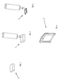
- the second product 9 is subjected to an emptying operation.
- An opening is created on product 9 to put its inner part, consisting of the matrix 7, in communication with the outer environment.
- This operation preferably comprises a drilling with a tool, as shown in Fig. 15 .
- drilling can be carried out using any technique within the reach of the industry.
- this step can be omitted if the second article 9 obtained in the previous steps of the method already has an open area in which the matrix 7 emerges at the surface.
- the matrix 7 of the second product 9 is subjected to the emptying step.
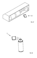
- Fig. 16 shows an emptying step of the second product in which the matrix is made of low-melting material.
- the second product 9 is mounted on a rotating frame 10 inside an emptying furnace 11, closed and kept at a melting temperature Ts, depending on the type of low-melting material constituting the core, for example 350°C.
- a first static heating step is followed by one or more rotating cycles, or that is, centrifugal cycles, in one direction and then in the opposite direction.
- the low-melting material melts and flows out of the opening previously made to then be collected on the bottom of the furnace in a special collection basin 12.
- the centrifugal action contributes to the complete emptying of the low-melting material.
- the emptying can take place keeping the second product in a furnace in a stationary position, static emptying, advantageously at a melting temperature Ts' lower than the temperature used for the centrifugal emptying process above.
- the low-melting material melts and flows out of the opening previously made by gravity to be collected in a special basin placed at the bottom of the furnace.
- the emptying of the matrix can take place chemically by placing the second product in tanks containing suitable chemicals able to react only with the matrix material and leaving the metal covering layer deposited during the electroforming step unaltered.
- a solution of ferric chloride can be used in the case of a matrix made of copper and a metal covering layer consisting of bronze.
- This process takes place preferably in polypropylene tanks heated with a water bath.
- chemical emptying is used in the emptying process of second products that were subjected to pre-electroforming treatments.
- the layer deposited during that step for example a copper layer as previously described, is advantageously and more effectively removed by chemical means.
- the emptying may foresee an initial thermal emptying step for the removal of the low-melting core followed by a second chemical emptying step for the effective removal of the layer deposited during the pre-electroforming step, typically a copper layer.
- the final object is substantially hollow, in this case a hollow buckle, comprising a metal layer created during the electroforming step.
- the physical and/or chemical characteristics of the hollow buckle of the invention, and in general of any hollow object manufactured by the method according to the present invention, are advantageously provided preferably by the covering metal layer created during the electroforming step.
- both the physical and/or chemical characteristics of the final object can be easily established during the design phase of the production cycles, given that the steps, particularly the electroforming, are controllable in a precise manner.
- the manufacturing of the final object avoids the use of toxic materials unlike what occurs with the methods of the prior art used to manufacture objects with similar characteristics and/or weight. Therefore, it is demonstrated that the present invention described above achieves the intended objectives.
- the present invention overcomes the problems related to the manufacturing of hollow metal objects with the current state of the art. While the present invention was described with reference to particular embodiments of the method shown in the figures, it should be noted that the present invention is not limited to the particular embodiments shown and described above. On the contrary, further embodiments of the method of manufacturing described fall within the scope of the present invention, which is defined by the claims.
Landscapes
- Chemical & Material Sciences (AREA)
- Engineering & Computer Science (AREA)
- Chemical Kinetics & Catalysis (AREA)
- Electrochemistry (AREA)
- Materials Engineering (AREA)
- Metallurgy (AREA)
- Organic Chemistry (AREA)
- Adornments (AREA)
- Analysing Materials By The Use Of Radiation (AREA)
Claims (11)
- Methode zur Herstellung eines hohlen Metallobjekts (1), wobei die besagte Methode folgende Schritte umfasst:- Vorbereitung eines Stützelements (7), wenigstens eine äußere Schicht aus einem elektrisch leitfähigen Material umfassend;- einen Schritt der Ablagerung einer Schicht aus einem Überzugmaterial auf dem besagten Stützelement (7) durch einen elektrochemischen Prozess, dazu geeignet, das besagte Metallobjekt (1) zu erzielen;- einen Schritt, in dem das besagte Stützelement (7) entleert wird, nach dem besagten Schritt der Ablagerung einer Schicht aus Überzugmaterial auf dem besagten Stützelement (7) durch einen elektrochemischen Prozess;dadurch gekennzeichnet, dass die besagte Methode des Weiteren Folgendes umfasst:- einen weiteren Schritt der Ablagerung einer Schicht eines zweiten, leitfähigen Materials auf dem besagten Stützelement (7) durch einen elektrochemischen Prozess, um eine glatte, glänzende und elektrisch leitfähige Oberfläche zu erzielen, wobei der besagte weitere Schritt der Ablagerung einer Schicht eines zweiten, leitfähigen Materials vor dem besagten Schritt der Ablagerung eines Überzugmaterials vorgenommen wird;- einen Schritt der Entleerung des besagten zweiten, leitfähigen Materials nach dem besagten Schritt der Entleerung des besagten Stützelements (7).
- Methode gemäß Patentanspruch 1), dadurch gekennzeichnet, dass das besagte Überzugmaterial kein edles Material ist.
- Methode gemäß Patentanspruch 1), dadurch gekennzeichnet, dass das besagte, nicht edle Material Bronze umfasst.
- Methode gemäß Patentanspruch 1), dadurch gekennzeichnet, dass das besagte Stützelement (7) vollständig aus einem leitfähigen Material gefertigt ist.
- Methode gemäß eines jeden der Patentansprüche von 1) bis 3), dadurch gekennzeichnet, dass das besagte Stützelement (7) ein nicht leitfähiges Material umfasst.
- Methode gemäß Patentanspruch 5), dadurch gekennzeichnet, dass sie einen Schritt des Auftrags der wenigstens einen äußeren Schicht eines elektrisch leitfähigen Materials auf dem besagten, ein nicht leitfähiges Material umfassenden Stützelement (7) umfasst;
- Methode gemäß eines jeden der vorstehenden Patentansprüche, dadurch gekennzeichnet, dass das besagte Stützelement (7) ein niedrig schmelzendes Material umfasst.
- Methode gemäß Patentanspruch 7), dadurch gekennzeichnet, dass der besagte Entleerungsschritt des besagten Stützelements einen Schritt der Entleerung durch einen thermischen Heizprozess umfasst, der geeignet ist, das besagte Stützelement (7) zu schmelzen.
- Methode gemäß Patentanspruch 8), dadurch gekennzeichnet, dass der besagte Entleerungsschritt einen Schritt umfasst, in dem der Entleerungsvorgang durch einen chemischen Prozess erfolgt.
- Methode gemäß eines jeden der vorstehenden Patentansprüche, dadurch gekennzeichnet, dass die besagte Schicht des besagten, leitfähigen Materials eine Kupferschicht ist.
- Methode gemäß eines jeden der vorstehenden Patentansprüche, dadurch gekennzeichnet, dass der besagte Schritt der Entleerung des besagten, zweiten leitfähigen Materials durch einen chemischen Prozess erfolgt.
Applications Claiming Priority (1)
| Application Number | Priority Date | Filing Date | Title |
|---|---|---|---|
| IT000214A ITVI20110214A1 (it) | 2011-08-01 | 2011-08-01 | Metodo di realizzazione di un oggetto metallico |
Publications (2)
| Publication Number | Publication Date |
|---|---|
| EP2554716A1 EP2554716A1 (de) | 2013-02-06 |
| EP2554716B1 true EP2554716B1 (de) | 2015-04-01 |
Family
ID=44584529
Family Applications (1)
| Application Number | Title | Priority Date | Filing Date |
|---|---|---|---|
| EP20120005057 Active EP2554716B1 (de) | 2011-08-01 | 2012-07-09 | Verfahren zur Herstellung metallischer Objekte |
Country Status (3)
| Country | Link |
|---|---|
| EP (1) | EP2554716B1 (de) |
| ES (1) | ES2537382T3 (de) |
| IT (1) | ITVI20110214A1 (de) |
Families Citing this family (1)
| Publication number | Priority date | Publication date | Assignee | Title |
|---|---|---|---|---|
| CN104499008B (zh) * | 2014-12-15 | 2017-02-01 | 福州小神龙表业技术研发有限公司 | 一种贵金属手表表壳或饰件的生产工艺 |
Family Cites Families (6)
| Publication number | Priority date | Publication date | Assignee | Title |
|---|---|---|---|---|
| US2851331A (en) * | 1956-04-23 | 1958-09-09 | Ideal Toy Corp | Electro-deposited mold |
| DE1256505B (de) * | 1963-03-14 | 1967-12-14 | Standard Elektrik Lorenz Ag | Verfahren zur galvanoplastischen Herstellung von Hohlleiterbauteilen mit verlorenem Kern |
| US3461045A (en) * | 1965-10-21 | 1969-08-12 | Teletype Corp | Method of plating through holes |
| US3554874A (en) * | 1968-05-31 | 1971-01-12 | Budd Co | Method of electroforming vessels |
| DE69600372D1 (de) * | 1995-02-14 | 1998-07-30 | Yasui & Co M | Verfahren zur Herstellung eines hohlen elektroformierten Produkts aus Edelmetall |
| DE60033570D1 (de) * | 1999-12-28 | 2007-04-05 | Smk Kk | Verfahren zur herstellung von metallhülsen und vorrichtung dafür |
-
2011
- 2011-08-01 IT IT000214A patent/ITVI20110214A1/it unknown
-
2012
- 2012-07-09 EP EP20120005057 patent/EP2554716B1/de active Active
- 2012-07-09 ES ES12005057.0T patent/ES2537382T3/es active Active
Also Published As
| Publication number | Publication date |
|---|---|
| ITVI20110214A1 (it) | 2013-02-02 |
| EP2554716A1 (de) | 2013-02-06 |
| ES2537382T3 (es) | 2015-06-08 |
Similar Documents
| Publication | Publication Date | Title |
|---|---|---|
| CN104499008B (zh) | 一种贵金属手表表壳或饰件的生产工艺 | |
| US5172568A (en) | Hollow jewelry objects and method | |
| US11208715B2 (en) | Method for decorating a timepiece component | |
| CN104499009A (zh) | 中空表壳或饰件的制作方法 | |
| US20060286400A1 (en) | Substrate with alloy finish and method of making | |
| CA2013639C (en) | Electroplated blank for coins, medallions and tokens | |
| EP2554716B1 (de) | Verfahren zur Herstellung metallischer Objekte | |
| CN110699713A (zh) | 一种无氰金合金电铸液及其使用方法 | |
| EP3112502B1 (de) | Verfahren zum plattieren von metallischen drähten oder bändern und produkt hergestellt mittels diesem verfahren | |
| GB2167444A (en) | Electroforming | |
| ITAR20060036A1 (it) | Procedimento per la formatura di articoli di bigiotteria cavi rivestiti con una patina di metallo o lega metallica di pregio | |
| JP2014525039A (ja) | 電鋳によって蒸着された時計の外側要素に装飾品を嵌め込むための方法及びこの方法によって作製される外側要素 | |
| CN1958861A (zh) | 人造首饰的制造方法 | |
| CN110693145A (zh) | 一种基于电铸的宝石镶嵌工艺 | |
| CN102899695B (zh) | 无镍合金镀层的电镀方法 | |
| EP2730683B1 (de) | Objekt mit Oberflächendeckschicht, die hergestellt ist durch elektrolytische Ablagerung, verwendete Elektrolytlösung für die Ablagerung und Verfahren zur Herstellung dieses Gegenstandes | |
| KR20090056196A (ko) | 마그네슘 합금을 이용한 차량 내장용 기능성 장식품 제조방법 | |
| ITUB20155234A1 (it) | Lega metallica e suo utilizzo | |
| KR100529969B1 (ko) | 전해주조 기술을 이용한 할로우 주얼리 형성 방법 | |
| CN103757673A (zh) | 一种佩戴饰品的制造方法 | |
| EP1621097A1 (de) | Verfahren zur Herstellung von Schmuckstücken und mit diesem Verfahren hergestellte Schmuckstücke | |
| CN1962955A (zh) | 空心工艺品制作方法 | |
| KR100579506B1 (ko) | 유사 금속층을 갖는 성형품 및 그 제조방법 | |
| WO2004020697A1 (en) | Method of producing jewelry | |
| CN102921760B (zh) | 一种具有镀层的金属工艺品线材的加工工艺 |
Legal Events
| Date | Code | Title | Description |
|---|---|---|---|
| PUAI | Public reference made under article 153(3) epc to a published international application that has entered the european phase |
Free format text: ORIGINAL CODE: 0009012 |
|
| AK | Designated contracting states |
Kind code of ref document: A1 Designated state(s): AL AT BE BG CH CY CZ DE DK EE ES FI FR GB GR HR HU IE IS IT LI LT LU LV MC MK MT NL NO PL PT RO RS SE SI SK SM TR |
|
| AX | Request for extension of the european patent |
Extension state: BA ME |
|
| 17P | Request for examination filed |
Effective date: 20130726 |
|
| RBV | Designated contracting states (corrected) |
Designated state(s): AL AT BE BG CH CY CZ DE DK EE ES FI FR GB GR HR HU IE IS IT LI LT LU LV MC MK MT NL NO PL PT RO RS SE SI SK SM TR |
|
| 17Q | First examination report despatched |
Effective date: 20140304 |
|
| GRAP | Despatch of communication of intention to grant a patent |
Free format text: ORIGINAL CODE: EPIDOSNIGR1 |
|
| INTG | Intention to grant announced |
Effective date: 20140918 |
|
| GRAS | Grant fee paid |
Free format text: ORIGINAL CODE: EPIDOSNIGR3 |
|
| GRAP | Despatch of communication of intention to grant a patent |
Free format text: ORIGINAL CODE: EPIDOSNIGR1 |
|
| INTG | Intention to grant announced |
Effective date: 20150204 |
|
| GRAA | (expected) grant |
Free format text: ORIGINAL CODE: 0009210 |
|
| AK | Designated contracting states |
Kind code of ref document: B1 Designated state(s): AL AT BE BG CH CY CZ DE DK EE ES FI FR GB GR HR HU IE IS IT LI LT LU LV MC MK MT NL NO PL PT RO RS SE SI SK SM TR |
|
| REG | Reference to a national code |
Ref country code: GB Ref legal event code: FG4D |
|
| REG | Reference to a national code |
Ref country code: CH Ref legal event code: EP |
|
| REG | Reference to a national code |
Ref country code: IE Ref legal event code: FG4D |
|
| REG | Reference to a national code |
Ref country code: DE Ref legal event code: R096 Ref document number: 602012006242 Country of ref document: DE Effective date: 20150513 |
|
| REG | Reference to a national code |
Ref country code: AT Ref legal event code: REF Ref document number: 719140 Country of ref document: AT Kind code of ref document: T Effective date: 20150515 |
|
| REG | Reference to a national code |
Ref country code: ES Ref legal event code: FG2A Ref document number: 2537382 Country of ref document: ES Kind code of ref document: T3 Effective date: 20150608 |
|
| PGFP | Annual fee paid to national office [announced via postgrant information from national office to epo] |
Ref country code: CH Payment date: 20150609 Year of fee payment: 4 |
|
| REG | Reference to a national code |
Ref country code: NL Ref legal event code: VDEP Effective date: 20150401 |
|
| REG | Reference to a national code |
Ref country code: AT Ref legal event code: MK05 Ref document number: 719140 Country of ref document: AT Kind code of ref document: T Effective date: 20150401 |
|
| REG | Reference to a national code |
Ref country code: LT Ref legal event code: MG4D |
|
| PG25 | Lapsed in a contracting state [announced via postgrant information from national office to epo] |
Ref country code: NL Free format text: LAPSE BECAUSE OF FAILURE TO SUBMIT A TRANSLATION OF THE DESCRIPTION OR TO PAY THE FEE WITHIN THE PRESCRIBED TIME-LIMIT Effective date: 20150401 |
|
| REG | Reference to a national code |
Ref country code: CH Ref legal event code: NV Representative=s name: SEDIN SA, CH |
|
| PG25 | Lapsed in a contracting state [announced via postgrant information from national office to epo] |
Ref country code: FI Free format text: LAPSE BECAUSE OF FAILURE TO SUBMIT A TRANSLATION OF THE DESCRIPTION OR TO PAY THE FEE WITHIN THE PRESCRIBED TIME-LIMIT Effective date: 20150401 Ref country code: PT Free format text: LAPSE BECAUSE OF FAILURE TO SUBMIT A TRANSLATION OF THE DESCRIPTION OR TO PAY THE FEE WITHIN THE PRESCRIBED TIME-LIMIT Effective date: 20150803 Ref country code: HR Free format text: LAPSE BECAUSE OF FAILURE TO SUBMIT A TRANSLATION OF THE DESCRIPTION OR TO PAY THE FEE WITHIN THE PRESCRIBED TIME-LIMIT Effective date: 20150401 Ref country code: CZ Free format text: LAPSE BECAUSE OF FAILURE TO SUBMIT A TRANSLATION OF THE DESCRIPTION OR TO PAY THE FEE WITHIN THE PRESCRIBED TIME-LIMIT Effective date: 20150401 Ref country code: LT Free format text: LAPSE BECAUSE OF FAILURE TO SUBMIT A TRANSLATION OF THE DESCRIPTION OR TO PAY THE FEE WITHIN THE PRESCRIBED TIME-LIMIT Effective date: 20150401 Ref country code: NO Free format text: LAPSE BECAUSE OF FAILURE TO SUBMIT A TRANSLATION OF THE DESCRIPTION OR TO PAY THE FEE WITHIN THE PRESCRIBED TIME-LIMIT Effective date: 20150701 |
|
| PGFP | Annual fee paid to national office [announced via postgrant information from national office to epo] |
Ref country code: DE Payment date: 20150728 Year of fee payment: 4 Ref country code: ES Payment date: 20150708 Year of fee payment: 4 |
|
| PG25 | Lapsed in a contracting state [announced via postgrant information from national office to epo] |
Ref country code: GR Free format text: LAPSE BECAUSE OF FAILURE TO SUBMIT A TRANSLATION OF THE DESCRIPTION OR TO PAY THE FEE WITHIN THE PRESCRIBED TIME-LIMIT Effective date: 20150702 Ref country code: LV Free format text: LAPSE BECAUSE OF FAILURE TO SUBMIT A TRANSLATION OF THE DESCRIPTION OR TO PAY THE FEE WITHIN THE PRESCRIBED TIME-LIMIT Effective date: 20150401 Ref country code: RS Free format text: LAPSE BECAUSE OF FAILURE TO SUBMIT A TRANSLATION OF THE DESCRIPTION OR TO PAY THE FEE WITHIN THE PRESCRIBED TIME-LIMIT Effective date: 20150401 Ref country code: IS Free format text: LAPSE BECAUSE OF FAILURE TO SUBMIT A TRANSLATION OF THE DESCRIPTION OR TO PAY THE FEE WITHIN THE PRESCRIBED TIME-LIMIT Effective date: 20150801 Ref country code: AT Free format text: LAPSE BECAUSE OF FAILURE TO SUBMIT A TRANSLATION OF THE DESCRIPTION OR TO PAY THE FEE WITHIN THE PRESCRIBED TIME-LIMIT Effective date: 20150401 |
|
| REG | Reference to a national code |
Ref country code: DE Ref legal event code: R097 Ref document number: 602012006242 Country of ref document: DE |
|
| PG25 | Lapsed in a contracting state [announced via postgrant information from national office to epo] |
Ref country code: EE Free format text: LAPSE BECAUSE OF FAILURE TO SUBMIT A TRANSLATION OF THE DESCRIPTION OR TO PAY THE FEE WITHIN THE PRESCRIBED TIME-LIMIT Effective date: 20150401 Ref country code: DK Free format text: LAPSE BECAUSE OF FAILURE TO SUBMIT A TRANSLATION OF THE DESCRIPTION OR TO PAY THE FEE WITHIN THE PRESCRIBED TIME-LIMIT Effective date: 20150401 |
|
| PLBE | No opposition filed within time limit |
Free format text: ORIGINAL CODE: 0009261 |
|
| STAA | Information on the status of an ep patent application or granted ep patent |
Free format text: STATUS: NO OPPOSITION FILED WITHIN TIME LIMIT |
|
| PG25 | Lapsed in a contracting state [announced via postgrant information from national office to epo] |
Ref country code: PL Free format text: LAPSE BECAUSE OF FAILURE TO SUBMIT A TRANSLATION OF THE DESCRIPTION OR TO PAY THE FEE WITHIN THE PRESCRIBED TIME-LIMIT Effective date: 20150401 Ref country code: RO Free format text: LAPSE BECAUSE OF NON-PAYMENT OF DUE FEES Effective date: 20150401 Ref country code: MC Free format text: LAPSE BECAUSE OF FAILURE TO SUBMIT A TRANSLATION OF THE DESCRIPTION OR TO PAY THE FEE WITHIN THE PRESCRIBED TIME-LIMIT Effective date: 20150401 Ref country code: SK Free format text: LAPSE BECAUSE OF FAILURE TO SUBMIT A TRANSLATION OF THE DESCRIPTION OR TO PAY THE FEE WITHIN THE PRESCRIBED TIME-LIMIT Effective date: 20150401 |
|
| 26N | No opposition filed |
Effective date: 20160105 |
|
| PG25 | Lapsed in a contracting state [announced via postgrant information from national office to epo] |
Ref country code: LU Free format text: LAPSE BECAUSE OF FAILURE TO SUBMIT A TRANSLATION OF THE DESCRIPTION OR TO PAY THE FEE WITHIN THE PRESCRIBED TIME-LIMIT Effective date: 20150709 |
|
| REG | Reference to a national code |
Ref country code: IE Ref legal event code: MM4A |
|
| PG25 | Lapsed in a contracting state [announced via postgrant information from national office to epo] |
Ref country code: SI Free format text: LAPSE BECAUSE OF FAILURE TO SUBMIT A TRANSLATION OF THE DESCRIPTION OR TO PAY THE FEE WITHIN THE PRESCRIBED TIME-LIMIT Effective date: 20150401 |
|
| REG | Reference to a national code |
Ref country code: FR Ref legal event code: PLFP Year of fee payment: 5 |
|
| PG25 | Lapsed in a contracting state [announced via postgrant information from national office to epo] |
Ref country code: IE Free format text: LAPSE BECAUSE OF NON-PAYMENT OF DUE FEES Effective date: 20150709 |
|
| PG25 | Lapsed in a contracting state [announced via postgrant information from national office to epo] |
Ref country code: BE Free format text: LAPSE BECAUSE OF FAILURE TO SUBMIT A TRANSLATION OF THE DESCRIPTION OR TO PAY THE FEE WITHIN THE PRESCRIBED TIME-LIMIT Effective date: 20150401 |
|
| REG | Reference to a national code |
Ref country code: DE Ref legal event code: R119 Ref document number: 602012006242 Country of ref document: DE |
|
| REG | Reference to a national code |
Ref country code: CH Ref legal event code: PL |
|
| GBPC | Gb: european patent ceased through non-payment of renewal fee |
Effective date: 20160709 |
|
| PG25 | Lapsed in a contracting state [announced via postgrant information from national office to epo] |
Ref country code: MT Free format text: LAPSE BECAUSE OF FAILURE TO SUBMIT A TRANSLATION OF THE DESCRIPTION OR TO PAY THE FEE WITHIN THE PRESCRIBED TIME-LIMIT Effective date: 20150401 |
|
| PG25 | Lapsed in a contracting state [announced via postgrant information from national office to epo] |
Ref country code: CH Free format text: LAPSE BECAUSE OF NON-PAYMENT OF DUE FEES Effective date: 20160731 Ref country code: LI Free format text: LAPSE BECAUSE OF NON-PAYMENT OF DUE FEES Effective date: 20160731 Ref country code: DE Free format text: LAPSE BECAUSE OF NON-PAYMENT OF DUE FEES Effective date: 20170201 |
|
| PG25 | Lapsed in a contracting state [announced via postgrant information from national office to epo] |
Ref country code: GB Free format text: LAPSE BECAUSE OF NON-PAYMENT OF DUE FEES Effective date: 20160709 Ref country code: BG Free format text: LAPSE BECAUSE OF FAILURE TO SUBMIT A TRANSLATION OF THE DESCRIPTION OR TO PAY THE FEE WITHIN THE PRESCRIBED TIME-LIMIT Effective date: 20150401 Ref country code: SM Free format text: LAPSE BECAUSE OF FAILURE TO SUBMIT A TRANSLATION OF THE DESCRIPTION OR TO PAY THE FEE WITHIN THE PRESCRIBED TIME-LIMIT Effective date: 20150401 Ref country code: HU Free format text: LAPSE BECAUSE OF FAILURE TO SUBMIT A TRANSLATION OF THE DESCRIPTION OR TO PAY THE FEE WITHIN THE PRESCRIBED TIME-LIMIT; INVALID AB INITIO Effective date: 20120709 |
|
| REG | Reference to a national code |
Ref country code: FR Ref legal event code: PLFP Year of fee payment: 6 |
|
| PG25 | Lapsed in a contracting state [announced via postgrant information from national office to epo] |
Ref country code: CY Free format text: LAPSE BECAUSE OF FAILURE TO SUBMIT A TRANSLATION OF THE DESCRIPTION OR TO PAY THE FEE WITHIN THE PRESCRIBED TIME-LIMIT Effective date: 20150401 Ref country code: SE Free format text: LAPSE BECAUSE OF FAILURE TO SUBMIT A TRANSLATION OF THE DESCRIPTION OR TO PAY THE FEE WITHIN THE PRESCRIBED TIME-LIMIT Effective date: 20150401 |
|
| PG25 | Lapsed in a contracting state [announced via postgrant information from national office to epo] |
Ref country code: TR Free format text: LAPSE BECAUSE OF FAILURE TO SUBMIT A TRANSLATION OF THE DESCRIPTION OR TO PAY THE FEE WITHIN THE PRESCRIBED TIME-LIMIT Effective date: 20150401 |
|
| PG25 | Lapsed in a contracting state [announced via postgrant information from national office to epo] |
Ref country code: ES Free format text: LAPSE BECAUSE OF NON-PAYMENT OF DUE FEES Effective date: 20160710 |
|
| REG | Reference to a national code |
Ref country code: ES Ref legal event code: FD2A Effective date: 20180626 |
|
| REG | Reference to a national code |
Ref country code: FR Ref legal event code: PLFP Year of fee payment: 7 |
|
| PG25 | Lapsed in a contracting state [announced via postgrant information from national office to epo] |
Ref country code: MK Free format text: LAPSE BECAUSE OF FAILURE TO SUBMIT A TRANSLATION OF THE DESCRIPTION OR TO PAY THE FEE WITHIN THE PRESCRIBED TIME-LIMIT Effective date: 20150401 |
|
| PG25 | Lapsed in a contracting state [announced via postgrant information from national office to epo] |
Ref country code: AL Free format text: LAPSE BECAUSE OF FAILURE TO SUBMIT A TRANSLATION OF THE DESCRIPTION OR TO PAY THE FEE WITHIN THE PRESCRIBED TIME-LIMIT Effective date: 20150401 |
|
| PGFP | Annual fee paid to national office [announced via postgrant information from national office to epo] |
Ref country code: IT Payment date: 20230615 Year of fee payment: 12 Ref country code: FR Payment date: 20230622 Year of fee payment: 12 |