EP2553386B2 - Procédé de mesure pour une machine de mesure mesurant les surfaces - Google Patents
Procédé de mesure pour une machine de mesure mesurant les surfaces Download PDFInfo
- Publication number
- EP2553386B2 EP2553386B2 EP11709710.5A EP11709710A EP2553386B2 EP 2553386 B2 EP2553386 B2 EP 2553386B2 EP 11709710 A EP11709710 A EP 11709710A EP 2553386 B2 EP2553386 B2 EP 2553386B2
- Authority
- EP
- European Patent Office
- Prior art keywords
- code
- relative
- sensor arrangement
- code carrier
- measurement
- Prior art date
- Legal status (The legal status is an assumption and is not a legal conclusion. Google has not performed a legal analysis and makes no representation as to the accuracy of the status listed.)
- Active
Links
Images

Classifications
-
- G—PHYSICS
- G01—MEASURING; TESTING
- G01D—MEASURING NOT SPECIALLY ADAPTED FOR A SPECIFIC VARIABLE; ARRANGEMENTS FOR MEASURING TWO OR MORE VARIABLES NOT COVERED IN A SINGLE OTHER SUBCLASS; TARIFF METERING APPARATUS; MEASURING OR TESTING NOT OTHERWISE PROVIDED FOR
- G01D5/00—Mechanical means for transferring the output of a sensing member; Means for converting the output of a sensing member to another variable where the form or nature of the sensing member does not constrain the means for converting; Transducers not specially adapted for a specific variable
- G01D5/26—Mechanical means for transferring the output of a sensing member; Means for converting the output of a sensing member to another variable where the form or nature of the sensing member does not constrain the means for converting; Transducers not specially adapted for a specific variable characterised by optical transfer means, i.e. using infrared, visible, or ultraviolet light
- G01D5/32—Mechanical means for transferring the output of a sensing member; Means for converting the output of a sensing member to another variable where the form or nature of the sensing member does not constrain the means for converting; Transducers not specially adapted for a specific variable characterised by optical transfer means, i.e. using infrared, visible, or ultraviolet light with attenuation or whole or partial obturation of beams of light
- G01D5/34—Mechanical means for transferring the output of a sensing member; Means for converting the output of a sensing member to another variable where the form or nature of the sensing member does not constrain the means for converting; Transducers not specially adapted for a specific variable characterised by optical transfer means, i.e. using infrared, visible, or ultraviolet light with attenuation or whole or partial obturation of beams of light the beams of light being detected by photocells
- G01D5/347—Mechanical means for transferring the output of a sensing member; Means for converting the output of a sensing member to another variable where the form or nature of the sensing member does not constrain the means for converting; Transducers not specially adapted for a specific variable characterised by optical transfer means, i.e. using infrared, visible, or ultraviolet light with attenuation or whole or partial obturation of beams of light the beams of light being detected by photocells using displacement encoding scales
-
- G—PHYSICS
- G01—MEASURING; TESTING
- G01C—MEASURING DISTANCES, LEVELS OR BEARINGS; SURVEYING; NAVIGATION; GYROSCOPIC INSTRUMENTS; PHOTOGRAMMETRY OR VIDEOGRAMMETRY
- G01C1/00—Measuring angles
-
- G—PHYSICS
- G01—MEASURING; TESTING
- G01B—MEASURING LENGTH, THICKNESS OR SIMILAR LINEAR DIMENSIONS; MEASURING ANGLES; MEASURING AREAS; MEASURING IRREGULARITIES OF SURFACES OR CONTOURS
- G01B21/00—Measuring arrangements or details thereof, where the measuring technique is not covered by the other groups of this subclass, unspecified or not relevant
- G01B21/02—Measuring arrangements or details thereof, where the measuring technique is not covered by the other groups of this subclass, unspecified or not relevant for measuring length, width, or thickness
- G01B21/04—Measuring arrangements or details thereof, where the measuring technique is not covered by the other groups of this subclass, unspecified or not relevant for measuring length, width, or thickness by measuring coordinates of points
- G01B21/045—Correction of measurements
-
- G—PHYSICS
- G01—MEASURING; TESTING
- G01D—MEASURING NOT SPECIALLY ADAPTED FOR A SPECIFIC VARIABLE; ARRANGEMENTS FOR MEASURING TWO OR MORE VARIABLES NOT COVERED IN A SINGLE OTHER SUBCLASS; TARIFF METERING APPARATUS; MEASURING OR TESTING NOT OTHERWISE PROVIDED FOR
- G01D5/00—Mechanical means for transferring the output of a sensing member; Means for converting the output of a sensing member to another variable where the form or nature of the sensing member does not constrain the means for converting; Transducers not specially adapted for a specific variable
- G01D5/26—Mechanical means for transferring the output of a sensing member; Means for converting the output of a sensing member to another variable where the form or nature of the sensing member does not constrain the means for converting; Transducers not specially adapted for a specific variable characterised by optical transfer means, i.e. using infrared, visible, or ultraviolet light
- G01D5/32—Mechanical means for transferring the output of a sensing member; Means for converting the output of a sensing member to another variable where the form or nature of the sensing member does not constrain the means for converting; Transducers not specially adapted for a specific variable characterised by optical transfer means, i.e. using infrared, visible, or ultraviolet light with attenuation or whole or partial obturation of beams of light
- G01D5/34—Mechanical means for transferring the output of a sensing member; Means for converting the output of a sensing member to another variable where the form or nature of the sensing member does not constrain the means for converting; Transducers not specially adapted for a specific variable characterised by optical transfer means, i.e. using infrared, visible, or ultraviolet light with attenuation or whole or partial obturation of beams of light the beams of light being detected by photocells
- G01D5/347—Mechanical means for transferring the output of a sensing member; Means for converting the output of a sensing member to another variable where the form or nature of the sensing member does not constrain the means for converting; Transducers not specially adapted for a specific variable characterised by optical transfer means, i.e. using infrared, visible, or ultraviolet light with attenuation or whole or partial obturation of beams of light the beams of light being detected by photocells using displacement encoding scales
- G01D5/3473—Circular or rotary encoders
Definitions
- the invention relates to a measuring method for a surface measuring machine according to the preamble of claim 1, a connecting arrangement, in particular a tilting or rotating connection, for a measuring machine according to the preamble of claim 6 and a coordinate measuring machine with an articulated arm according to claim 12.
- Measuring methods and machines such as coordinate measuring machines or machines with articulated arms, have been around for a long time. These devices are used, for example, for the high-precision measurement of object surfaces, particularly in the manufacturing industry, where the measurement and inspection of workpiece surfaces is of great importance.
- 3D coordinate measuring articulated arms have a fixed base position in a known reference coordinate system as one end of the articulated arm and an opposite movable measuring end, on which a measuring component or measuring probe is mounted.
- a tactile probe can be used as a standard probe, which can be brought into contact with a measuring point on an object's surface and consists, for example, of a ruby sphere mounted on a measuring rod.
- optical sensors are also known as measuring components. These can be designed, for example, as point sensors or scanners, i.e., they can continuously scan an object surface, e.g., line-by-line.
- triangulation sensors or interferometric measuring arrangements can be used as such optical sensors.
- European Patent Application No. 07124101.2 The use of a camera as a measuring component is described. This camera is designed to record or capture the surface of a measuring object and is mounted on the movable end of an articulated arm. Using the articulated arm coordinate measuring machine, the position and orientation of the camera in space can be determined with high precision.
- links or arm sections are arranged that can be pivoted and/or rotated relative to one another and, if necessary, displaced relative to one another, so that the measuring end with the measuring component, also referred to as the sensing link, can move freely within a spatial section.
- the links of the arm are connected to one another by means of joints and, if necessary, by suspensions that enable linear displacement.
- position measuring devices are assigned to the joints or suspensions so that the position or orientation of the links relative to one another, i.e. a relative position between the links, can be measured.
- protractors and/or length gauges are used for this purpose, which determine lengths, angles of rotation or pivoting as measured variables.
- the rotary joints of an articulated arm are each assigned an optical-electronic protractor, which is used to determine the relative rotational position of the two links connected by the joint.
- the joint generally consists of two arm links that are rotatably connected to one another, with a rotary encoder or protractor arranged between them.
- the optical-electronic protractor or rotary encoder serves to measure the current relative rotational position of its rotary bearing components to one another, and thus indirectly of the two arm links.
- it has a code carrier or code element arranged on one of the two arm links, and a sensor arrangement that is correspondingly attached to the other arm link.
- pattern elements are optically imaged as a code of the code carrier onto the sensor arrangement comprising one or more reading heads, e.g. CCD or CMOS line or area sensors, as for example in the CH 658514 revealed.
- the sensor arrangement comprising one or more reading heads, e.g. CCD or CMOS line or area sensors, as for example in the CH 658514 revealed.
- the relative rotation angle of the code carrier as a rotating body relative to the sensor array can be determined from the position of the sensor array or its read heads.
- a detector center serves as a reference value; ideally, without mechanical eccentricity errors, both the detector center, the pivot point, and the center of the pattern elements lie on the rotation axis.
- the sensor arrangement must be positioned so that it is stable relative to the bearing.
- a high degree of dimensional and geometrical accuracy of the code carrier in particular the arrangement and design of the code element on the code carrier – with pattern elements arranged one behind the other in the direction of rotation around a pattern center — is a mandatory requirement.
- a spacing of the pattern center from the axis of rotation known as eccentricity, often makes it impossible to achieve the required levels of accuracy. Due to manufacturing tolerances that are difficult to avoid and always present in practice, every code carrier exhibits eccentricity.
- Concentricity deviations of the bearing or bearing play can also contribute to eccentricity. If significant loads are exerted on the swivel joints of the articulated arm when determining the scanning position or the angle of rotation, permanent or temporary eccentricities as well as other changes in the position of the code carrier relative to the swivel joint holder can occur, depending on the loads.
- the positions of the imaged pattern elements are resolved using the detector elements of one and the same detector.
- the effects of an eccentricity of the pattern center relative to the axis on the determination of a rotation angle are calculated using the resolved positions of at least one pattern element.
- the rotation angle is precisely determined using the resolved positions of consecutively arranged pattern elements, taking into account the determined effects.
- consecutively arranged pattern elements are combined into at least two groups via an intermediate step. At least two group positions are calculated using the resolved individual positions of the combined pattern elements. The effects of eccentricity on the determination of the angle of rotation are then calculated using the at least two determined group positions. This can be done with greater accuracy using the determined group positions.
- WO 2008/083797 In the international patent application WO 2008/083797 is described how, in order to determine an eccentricity error for an angle of rotation about an axis, the eccentricity of the pattern center relative to the detector center is calculated in a first step for a large number of measurements using resolved positions of pattern elements projected onto a sensor arrangement.
- at least one influencing variable can be separated or determined from the large number of measured values by aggregation, i.e. by summarizing and linking.
- the influencing variables are either determined or suppressed, e.g. by averaging.
- Certain influencing variables can then be used either algorithmically or to directly correct the eccentricity, e.g. to mechanically correct the axis position using control elements or electronically by adaptation.
- the movement in the direction of the rotation axis can also be determined using suitable angle measuring heads.
- the change in the distance between the code element and the sensor arrangement changes the projection scale of the code. This change in the projection scale can be used as a measure of the change in distance or the position in the axial direction. If the distances to the code disk as the code element are determined for two detector elements, the tilt of the axis can also be determined.
- two reading heads offset by 180° in the circumferential direction three by 120° each or alternatively four by 90° each are provided.
- An object of the invention is therefore to provide an improved measuring method for a surface measuring machine, in particular for a coordinate measuring machine with an articulated arm having rotary or tilting joints, for determining the measuring position of a measuring component.
- a further objective is to provide an improved coordinate measuring machine with an articulated arm featuring pivot joints as connecting arrangements.
- this should enable the measurement component measurement position to be determined with greater accuracy while requiring minimal hardware modifications to the articulated arm.
- the measuring method according to the invention for a surface measuring machine differs from prior art methods in which consideration or compensation for error influences—such as load-induced displacements or tilting of the rotation axis—is always provided only within the scope of determining an angular position of the swivel or tilt joint, with the arm links being considered as connecting elements from the base to the measurement component as unaffected.
- such changes in the position of the code carrier of a swivel joint, which is rotatably mounted in a holder, relative to the associated sensor arrangement are explicitly determined and used as additional measured variables that describe the measurement position of the arm links of the articulated arm to derive the measurement position of the measurement component relative to a base.
- a change in the position of the two arm links connected via the swivel or tilt joint, caused, for example, by loads, which goes beyond a change in rotational position is determined in its extent and taken into account when determining the relative position of the two arm links to each other.
- these position values can also be used to determine deformations or changes in the size of components.
- the position measuring device has a code that is applied to one of the rotary joint components - either directly or via a separate component - and a sensor arrangement comprising at least one read head.
- the sensor arrangement is arranged on the other rotary joint component and detects a code projection generated using the code carrier.
- a code projection is understood to be a projection of at least part of an optically detectable code that the code element has.
- a separate code disk which is connected to one of the articulated arm links, serves as the code carrier.
- the code can also be located directly on one of the arm links, so that this structurally serves as the code carrier.
- a position value for the additional degrees of freedom of the code carrier relative to the associated sensor arrangement is now determined for the rotary encoder based on the code projection and taken into account when determining the current measurement position of the measuring component or the probe.
- a relative position of the connecting element relative to the associated receptacle or its deformation is determined from the position value.
- the determination of the measurement position can be based on model-based approaches, which take into account the geometric and material-dependent parameters of the connecting elements, such as their length and dead or external weight, or a calibration-based solution, in which known positions and orientations are assigned corresponding position values, which in turn can provide a basis for a descriptive function or can be stored in look-up tables.
- model-based approaches which take into account the geometric and material-dependent parameters of the connecting elements, such as their length and dead or external weight, or a calibration-based solution, in which known positions and orientations are assigned corresponding position values, which in turn can provide a basis for a descriptive function or can be stored in look-up tables.
- these approaches can also be combined, e.g., by performing additional calibrations in selected measurement positions based on a model.
- other sensors such as temperature sensors, can also be used to supplement the model with specific parameters.
- the extent of any tilting of the code carrier of a rotary joint around the actual axis of rotation is detected and directly taken into account as the current relative measuring position of the links connected via the rotary joint to one another and is thus included in the determination of the measuring position of the probe.
- thermally induced changes such as changes in length or radius, already have an impact on the measuring position, which can also be taken into account or detected by the inventive approach.
- the sensor arrangement of the position measuring device can, in particular, consist of at least two read heads.
- the sensor arrangement can consist of two read heads offset by 90° in the circumferential direction, or alternatively, three read heads with an offset of 60° each.
- the read heads can be designed in a known manner, e.g., as line sensors with a plurality of detector elements arranged in a row.
- a code disk with an optically readable code is used as the code element or code carrier, using the transmitted light method.
- the code can comprise a plurality of pattern elements arranged one behind the other in the circumferential direction, whereby the entirety of the pattern elements can represent either an incremental or an absolute code.
- the code can also be located on other carriers, e.g., on the end face of housing components, which can then be illuminated, for example, using the incident light method.
- an optical-electronic rotary encoder such as is already present in some prior art rotary joints of articulated arms, can preferably be used as the position measuring device.
- a further rotary encoder or another functionally similar form of combination of code carrier and sensor arrangement can be provided as an optical-electronic position measuring device, which serves specifically to detect changes in the position of the code carrier relative to the sensor arrangement.
- the coordinate measuring machine designed according to the invention has an evaluation unit for this purpose, by means of which the arm position measurement variables recorded by individual link position sensors - including, according to the invention, also the position change variables with respect to the at least one rotary joint - are linked together and the measurement position of the measurement component is derived therefrom.
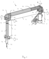
- Figure 1 shows purely by way of example a generic coordinate measuring machine 1 with an articulated arm for determining the position of a measuring point as an example of a measuring machine for surface measurement.
- the coordinate measuring machine 1 has a base 4, which is fixed and known in a reference coordinate system. Starting from the base, seven arm links 5a-5g are connected to one another as connecting elements via joints enabling relative rotary movements and/or via suspensions enabling relative linear movements. For illustration purposes, i.e. for a more understandable representation, these joints and suspensions are in Figure 1 not explicitly shown, although generic joints and suspensions are already sufficiently known to the expert.
- a first of the links 5a is attached to the base 4 so as to be movable relative to the latter, a second of the links 5b is attached to the first link 5a so as to be movable relative to the latter, etc.
- the seventh link 5g has a measuring component 6 and, as a structural element, forms the probe element TG.
- the measuring component 6 is thus freely movable within a spatial section and can, for example, be manually moved into a measuring position by a user, with mechanical contact with the base 4 being ensured by the sequence of connecting elements.
- the probe 6 is designed as a ruby ball for contacting a point on an object surface to be measured, although non-contact measuring systems can also be arranged and used in the same way.
- measuring components can also be used instead of the tactile probe.
- optical sensors in particular an optical distance meter, e.g. interferometric measuring arrangements, a laser scanner or a camera for scanning the surface can be used as measuring components.
- the measuring position is specified, for example, as the coordinates of a reference point of the measuring component 6 and, in particular, additionally as a current orientation of the measuring component 6 in the respective current measuring position.
- position measuring devices 8a-8f are assigned to each joint or suspension for measuring the relative positions of the links 5a-5g.
- optical-electronic rotary encoders as position measuring devices 8a, 8c, 8d, 8f and linear encoders as position measuring devices 8b, 8e are provided as the position measuring devices 8a-8f.
- These linear encoders are designed to measure arm position measurement variables ⁇ , ⁇ , ⁇ , ⁇ , ⁇ , a, b, c associated with the relative position of the links.
- angles ⁇ , ⁇ , ⁇ , ⁇ , ⁇ and length deflections a, b, c between the links 5a-5g are measured as arm position measurement variables ⁇ , ⁇ , ⁇ , ⁇ , ⁇ , a, b, c.
- An evaluation unit 7 is configured to receive the arm position measurement variables ⁇ , ⁇ , ⁇ , ⁇ , ⁇ , a, b, c determined for a measurement position. Based on these arm position measurement variables ⁇ , ⁇ , ⁇ , ⁇ , ⁇ , a, b, c, which indicate the relative positions of the arm links to each other, the evaluation unit derives the measurement position or the coordinates of the measurement component 6 and displays them, for example, on a display.
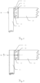
- Figure 2 shows a connection arrangement, e.g. of an articulated arm, for use with a measuring method, wherein the connection arrangement has a rotary encoder 9 which detects the rotation of the at least one connection element 10, e.g. a first arm link, relative to a receptacle 11, e.g. as the end of a second arm link.
- the measuring component is indirectly connected to the base by a sequence of connection elements 10, although according to the invention, measuring machines with only a single connection element 10 and thus a direct connection of the measuring component to the base by this one connection element 10 can also be realized.
- the rotary encoder 9 comprises a code carrier 12 and a sensor arrangement 13, wherein the code carrier 12 and the sensor arrangement 13 are rotatable relative to one another about a defined axis of rotation DA as a first degree of freedom.
- a code projection dependent on the three-dimensional position of the code carrier 12 relative to the sensor arrangement 13 is generated on the sensor arrangement 13, and at least part of the code projection is detected by the latter.
- the rotary encoder 9 is constructed in a manner known per se from a code carrier 12 rigidly connected to the holder 11 and having an optically detectable code, which can be designed, for example, as a code-bearing glass or plastic disc, and the sensor arrangement 13 consisting of one or more detector elements for detecting the code projection, which can be mounted accordingly in the connecting element 10.
- the sensor arrangement 13 can for this purpose, for example, have two read heads, each with a row arrangement of optical detector elements.
- the sensor arrangement 13 arranged in the connecting element 10 consists in the Figures 2 to 6 For example, two reading heads - e.g., as known from the prior art.
- the code carrier 12 is assigned as a code carrier with a code disk acting as a "measuring table" with a code extending in the circumferential direction.
- the code can have a plurality of pattern elements arranged in a row, wherein the pattern elements - e.g., in a triangular shape - are designed such that the code projection is particularly suitable for additional reading of position changes in the non-rotational direction.
- the arrangement of the sensor arrangement 13 in the connecting element 10 and the mechanically rigid connection of the code carrier 12 with the Receptacle 11 represents only one example. In particular, this arrangement can also be reversed, ie according to the invention, a mechanically rigid arrangement of the code carrier 12 in the connecting element 10 and the mechanically rigid connection of the sensor arrangement 13 to the receptacle 11 can also be realized.
- the position measuring device in particular the rotary encoder 9, must now take into account the determined displacements or tiltings of the code carrier in the non-rotational direction, which have a distorting effect on the angle measurement, not only internally in the rotary encoder when determining the angle, but also as further measuring position variables in addition to the determined angular position to a higher-level evaluation unit, which calculates the measuring position, for example, from all measuring position variables of all link position meters present in the articulated arm.
- the rotational position of the code carrier 12 relative to the defined axis of rotation DA is determined and, using this information available for all connecting elements, the current measuring position of the measuring component relative to the base is determined.
- a position value for at least one further degree of freedom of the code carrier 12 relative to the sensor arrangement 13 is also determined based on the code projection and taken into account when determining the current measurement position, whereby a relative position of the connecting element 10 with respect to the receptacle 11 and/or its deformation corresponding to the further degree of freedom of the code carrier is determined from the position value.
- the protractors used in the prior art also partially determine lateral displacement or changes in the distance of the code from the detectors, they only use this information to increase the accuracy of the angle measurement, i.e., to determine the rotational position.
- the position value for the further degree of freedom is used to draw conclusions regarding the position or orientation of the connecting element 10 and, if applicable, the acting forces or a deformation of the connecting element 10, whereby the position or orientation of the connecting element corresponds to the further degree of freedom of the code carrier 12.
- An eccentricity of the code carrier 12 is thus used to determine an eccentric position of the connecting element 10 relative to the receptacle 11.
- deviations in the value of the variable describing the further degree of freedom can occur due to errors or changes in the relative positioning of the code carrier 12 and the connecting element 10.
- a corresponding tilt of the connecting element 10 relative to the receptacle 11 is inferred. This tilt can be greater or smaller than the value of the tilt of the code carrier 12, for example due to elastic influences. In both cases, however, the degree of freedom of a tilt or rotation about the associated tilt axis is considered.
- the code projection can now be read out and, from this, positional changes of the code element or code carrier 12 relative to the sensor arrangement 13 - i.e., for example, deviations of a code center from the axis of rotation DA - caused by runout errors and loads on the rotary joint can be derived.
- these positional changes are taken into account as variables that indicate the relative position of the connecting element 10, e.g., in the case of an articulated arm, of the first to the second arm link, and are used as measurement position variables when calculating the position of the measuring component relative to the base.
- positional changes of the code carrier 12 relative to the sensor arrangement 13 that exceed a rotation angle are explicitly determined from the detected code projection and used to determine the measurement position.
- At least one, but in particular all of the following position changes or position values are determined: a displacement in the radial direction relative to the axis of rotation DA, a displacement in the direction of the axis of rotation DA and a tilting about the axis of rotation DA.
- the position values can be determined from the same code projection that is also used to read the angular position of the code element relative to the sensor arrangement.
- the determined position values can also be used for correction and/or calibration when determining the angular position.
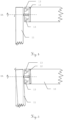
- Figures 3 to 6 show, by way of example, changes in position in the non-rotation direction of the code carrier 12 relative to the sensor arrangement 13 caused by loading of the rotary joint.
- the code carrier 12 is displaced relative to the sensor arrangement 13 in the direction of the rotation axis DA.
- Such a change in position can be derived from the code projection, for example, from a change in scale of the code projection detected by the sensor arrangement.
- the corresponding change in position can then be transmitted to the evaluation unit as an axial displacement amount ( ⁇ h) with respect to this rotary joint.
- the code carrier 12 is displaced in the radial direction relative to the sensor arrangement 13 and with respect to the rotation axis DA.
- a change in position can be derived from the code projection, for example, based on displacements of the positions of the pattern elements resolved by the sensor arrangement 13.
- the associated change in position variables can then be transmitted to the evaluation unit as the radial displacement direction (RR) and the radial displacement extent ( ⁇ r) with respect to this rotary joint.
- the code carrier 12 is tilted relative to the sensor arrangement 13 and with respect to the rotation axis DA.
- a change in position can be derived from the code projection, for example, from a scale ratio of the code projection detected by the first reading head to the code projection detected by the second reading head.
- the associated change in position variables can be transmitted to the evaluation unit, for example, as the tilt direction and tilt angle ( ⁇ ) with respect to this rotary joint.
- a function of the bending of one of the arm links as a function of the tilting about the rotation axis can be established, derived from deformation laws for solids and/or determined by empirical experiments.
- An example of such a function is shown in Figure 7 shown, with the extent of the bending ⁇ L of the corresponding arm link being plotted – purely schematically and in principle – against the determined tilt angle p.
- the function can be selected such that the extent of the arm joint bending is set to zero up to a tilt angle predetermined by a bearing play in the swivel joint.
- the forces acting on the arm links are essentially completely transferred to the joints by the usually very rigid bodies of the arm links, where they initially cause the tilting around the axis of rotation within the scope of the swivel joint play. If the code carrier has reached a stop in the swivel joint due to tilting, further force exertion also causes a deformation of the arm links, essentially in the form of bending.
- the position- and weight-dependent deformation described above can also be modeled.
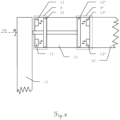
- FIG 8 an alternative embodiment for a connection arrangement in the form of a rotary joint with two rotary encoders 9 and 9' is shown.
- a first rotary encoder 9 and a second rotary encoder 9' are assigned to the rotary joint, in which the two optically detectable code disks are arranged as first and second code carriers 12 and 12' at a distance from each other on a common axis as the rotation axis DA.
- a sensor arrangement 13 and 13' comprising at least two reading heads is assigned to each of the two code disks, wherein the sensor arrangements 13 and 13' each capture a code element projection and are arranged opposite each other in the connecting element 10.
- Such an arrangement as a protractor and additionally as a measuring instrument for axial and/or radial displacements or tilts of the code carrier enables highly precise determination of the exact three-dimensional position or position of the code carriers 12 and 12' relative to the sensor arrangements 13 and 13'.
- This precisely determined position which is recorded using measurement position variables such as an angle of rotation around the axis of rotation, a radial displacement direction, a radial displacement extent, an axial displacement extent, a tilt direction and/or a tilt angle, can be related to one another, taking into account the rigid coupling of the code carriers 12 and 12' on the one hand and the sensor arrangements 13 and 13' on the other hand.
- the expansion and change in length of the common axis or the housing of the connecting element can be detected and quantified based on the change in distance between the code carriers 12 and 12' and the respective sensor arrangements 13 and 13'.
- the axis is assumed to be rigid and the code carriers 12, 12' and the sensor arrangements 13, 13' in the rotary encoders 9 and 9' tilt in opposite directions, it can be concluded that the connecting element 10 is deformed. In the case of tilting in the same direction, however, a largely rigid behavior of the connecting element 10 and its overall movement can be concluded.
- the extensive or complete replacement of other sensors in measuring machines e.g., pure length-measuring sensors
- can be achieved so that a complete and highly precise determination of the measuring position or spatial location of the measuring component is possible solely through the use of uniformly constructed rotary encoders.
- the resulting exclusive use of a single sensor type can simplify the mechanical and electronic design.
- each of the connecting arrangements between the arm links can be designed with two rotary encoders each arranged on a common axis of rotation, so that in addition to the relative position of the connecting element with respect to its holder, deformations as deviations from the desired shape, i.e., both deformations and scale changes, such as enlargement or reduction of length or diameter, can be determined.
- deformations as deviations from the desired shape, i.e., both deformations and scale changes, such as enlargement or reduction of length or diameter
- additional sensors can be used which, however, do not directly measure the spatial position but provide additional parameters, such as temperature sensors, which allow conclusions to be drawn about the temperature-induced deformation of the components.
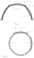
- the code carrier's pattern exemplified as a bar pattern, comprises a plurality of pattern elements 14 arranged one behind the other around a pattern center at the same distance from one another in the direction of rotation.
- pattern elements are designed, for example, as opaque, radially aligned bars. Beams passing between the bars image a portion of the bar pattern as bright and dark areas on the light-sensitive detector elements.
- the outward-facing and inward-facing end faces of the beams form two concentric, discontinuous circular lines that embody patterns symmetrical to the pattern center.
- the lengths L1 and L2 of the entry and exit points of the respective beams into and out of the spatially resolving range can be resolved here, particularly during a rotation of the beam pattern.
- a radial displacement and/or tilt for example, can then be mathematically determined.
- the position value can be mathematically determined based on a position of at least one of the pattern elements 14, a relationship between the positions of several of the pattern elements 14 to one another, or a sequence of positions of several pattern elements 14 arranged one behind the other.
- the code or the code projection onto the sensor arrangement can also be designed redundantly, i.e. as overdetermined with regard to the size to be determined, so that the additional information available through the redundancy can be used.
- Figure 10 shows an embodiment that differs from the Figure 9
- the code carrier differs from the embodiment shown by two sensor rows 5d and 5e offset by 90° as the sensor arrangement and by a different design of the pattern, in particular the pattern elements 14' arranged one behind the other in the direction of rotation and aligned radially towards the pattern center.
- the code carrier is embodied here by a translucent glass pane with opaque triangles.
- the code carrier rotatable about the axis could also be designed, for example, in the form of a thin metal disk, which here has triangular recesses embodying the pattern elements 14' arranged one behind the other in the direction of rotation.
- the design of the pattern elements 14' - for example, a triangular one - in which mutually facing side lines of adjacent, successively arranged pattern elements 14' are substantially inclined relative to the radial direction, has, due to the additional inclination relative to the radial direction, a greater sensitivity with regard to detecting displacements or tilts of the code carrier by the spatially resolving region. It even allows such changes in the position of the code carrier to be detected by resolving the width of a single triangle, which is shown here for the two widths 16 and 17 of the region projected onto the sensor line 15d. For example, the position or its displacement in the radial direction here can be detected from the width 16 of the projection, and its extent can be determined.
- the sensor arrangement of the rotary encoder can generally and depending on the code design and accuracy requirements have either one or two or more read heads or sensor lines.
- area sensors i.e. two-dimensional arrangements of pixel sensors, can also be used.
- two or more read heads these can, for example, be arranged offset by 180° from one another in the circumferential direction, whereby with four read heads they can each be offset by 90° in the circumferential direction.
- three read heads these can each be offset by 120°.
- sensor arrangements of the rotary encoder can be implemented with, for example, at least four read heads that are offset from one another in the circumferential direction at different angles, so that, for example, all angular distances differ from one another, in particular they are not in any multiple ratio to one another.
- a single area sensor can be used, which is arranged on the axis of rotation or detects this and an adjacent area and thus covers a large angular range in the area near the axis or even the entire angular range.
- code patterns can be applied to two opposite end surfaces of a code carrier, each of which is assigned a surface sensor covering the axis of rotation.
- Such arrangements with surface codes, which are detected by a corresponding sensor, are known, for example, from WO 2008/019855 known.
Landscapes
- Physics & Mathematics (AREA)
- General Physics & Mathematics (AREA)
- Engineering & Computer Science (AREA)
- Radar, Positioning & Navigation (AREA)
- Remote Sensing (AREA)
- Length Measuring Devices With Unspecified Measuring Means (AREA)
- Optical Transform (AREA)
- A Measuring Device Byusing Mechanical Method (AREA)
- Manipulator (AREA)
Claims (13)
- Procédé de mesure pour une machine à mesurer les surfaces, notamment une machine à mesurer les coordonnées (1), comprenant :- une base (4),- un composant de mesure (6) destiné à établir et à maintenir une liaison de mesure avec ou sans contact, notamment optique, avec une surface à mesurer, le composant de mesure (6) étant lié à la base (4) par au moins un élément de liaison (10),- au moins un codeur rotatif (9, 9') qui capte la rotation de l'au moins un élément de liaison (10) par rapport à une monture (11) et qui présente respectivement un support de code (12, 12') sous forme d'un disque de code et un agencement de capteur (13, 13'), le support de code et l'agencement de capteur pouvant tourner l'un par rapport à l'autre sur un axe de rotation (DA) défini, selon un premier degré de liberté,ledit procédé comprenant :• l'obtention d'une projection de code sous forme d'une ombre portée dudit disque de code sur l'agencement de capteur (13, 13'), ladite projection dépendant de la position tridimensionnelle du support de code (12, 12') relativement à l'agencement de capteur (13, 13'), et la détection d'au moins une partie de la projection de code,• la détermination d'une position de rotation du support de code (12, 12') autour de l'axe de rotation (DA) compte tenu de la projection de code,• la détermination de la position de mesure actuelle du composant de mesure (6) relativement à la base (4), en utilisant la position de rotation de l'au moins un codeur rotatif (9, 9'),
caractérisé en ce quepour l'au moins un codeur rotatif (9, 9') et compte tenu de la projection de code, une valeur de position est déterminée pour au moins un degré de liberté supplémentaire du support de code (12, 12') relativement à l'agencement de capteur (13, 13'), et est prise en compte lors du calcul de la position de mesure actuelle en tant que grandeur de mesure supplémentaire qui fournit une position relative de l'élément de liaison (10) par rapport à la monture (11),la position relative de l'élément de liaison (10) par rapport à la monture (11), correspondant à l'au moins un degré de liberté supplémentaire du support de code (12, 12'), étant déterminée à partir de la valeur de position,sachant que• une déviation du support de code (12, 12') à partir d'une position de repos,∘ en direction radiale relativement à l'axe de rotation (DA) et∘ en direction de l'axe de rotation (DA) et• un basculement du support de code (12, 12') à partir d'une position de repos relativement à l'agencement de capteur (13, 13'),
sont déterminés en tant que valeur de position et pour l'au moins un codeur rotatif (9, 9'), une position de rotation, une déviation et un basculement, et donc la position du support de code (12, 12'), sont déterminés relativement à l'agencement de capteur (13, 13') selon la totalité des six degrés de liberté, la position tridimensionnelle du support de code (12, 12') par rapport à l'agencement de capteur (13, 13') étant lue à cette fin sur ladite ombre portée. - Procédé de mesure selon l'une des revendications précédentes,
caractérisé en ce que
pour l'au moins un codeur rotatif (9, 9'), il est effectué une division en parties conditionnées par la déformation et par la position relative, compte tenu de l'orientation d'un autre élément de liaison lié à la monture (11). - Procédé de mesure selon l'une des revendications précédentes,
caractérisé en ce que
pour au moins un deuxième codeur rotatif (9'), sa position de rotation et sa valeur de position sont déterminées et prises en compte lors de la détermination de la position dans l'espace du composant de mesure (6). - Procédé de mesure selon la revendication 3,
caractérisé en ce que
la position de mesure est déterminée compte tenu de la position dans l'espace des éléments de liaison établie exclusivement à partir des positions de rotation et des valeurs de position des au moins deux codeurs rotatifs (9, 9'). - Procédé de mesure selon l'une des revendications précédentes,
caractérisé en ce que
le codeur rotatif (9, 9') présente au moins deux supports de code (12, 12') qui peuvent tourner sur le même axe de rotation, notamment un axe de rotation commun, et qui sont disposés à distance l'un de l'autre, une valeur de position étant déterminée pour chacun des supports de code (12, 12') compte tenu de la projection de code respective, une position relative de l'élément de liaison (10) par rapport à la monture (11), correspondant notamment au degré de liberté supplémentaire du support de code (12, 12'), et/ou la déformation de l'élément de liaison (10) étant déterminées à partir de la combinaison des valeurs de position des deux supports de code (12, 12'). - Agencement de liaison, notamment de liaison de basculement ou de rotation, pour une machine à mesurer, notamment dotée d'un bras articulé, comprenant :• un élément de liaison (10) pour lier indirectement ou directement une base (4) à un composant de mesure (6) destiné à établir et à maintenir une liaison de mesure avec une surface à mesurer,• au moins un codeur rotatif (9, 9') qui capte la rotation de l'au moins un élément de liaison (10) par rapport à une monture (11) et qui présente respectivement un support de code (12, 12') sous forme d'un disque de code et un agencement de capteur (13, 13'), le support de code (12, 12') et l'agencement de capteur (13, 13') pouvant tourner l'un par rapport à l'autre sur un axe de rotation (DA) défini, selon un premier degré de liberté, et• une unité d'évaluation (7) destinée à déterminer laposition de mesure actuelle de la machine à mesurer, caractérisé en ce quele codeur rotatif (9, 9') est conçu pour déterminer et fournir, à partir de la projection de code sous forme d'une ombre portée du disque de code, au moins une valeur de position concernant au moins un des cinq degrés de liberté supplémentaires de la position tridimensionnelle du support de code (12, 12') relativement à l'agencement de capteur (13, 13'), à savoir :• une déviation du support de code (12, 12') en direction radiale relativement à l'axe de rotation (DA),• une déviation du support de code (12, 12') en direction de l'axe de rotation (DA) et• un basculement du support de code (12, 12') par rapport à l'axe de rotation (DA),et l'unité d'évaluation (7) est conçue pour calculer la position de mesure actuelle en tenant compte de la valeur de position en tant que grandeur de mesure supplémentaire qui fournit une position relative de l'élément de liaison (10) par rapport à la monture (11), la position relative de l'élément de liaison (10) par rapport à la monture (11), correspondant à l'au moins un degré de liberté supplémentaire du support de code (12, 12'), pouvant être déterminée à partir de la valeur de position,sachant que pour l'au moins un codeur rotatif (9, 9'), une position de rotation, une déviation et un basculement, et donc la position du support de code (12, 12'), sont déterminés relativement à l'agencement de capteur (13, 13') selon la totalité des six degrés de liberté, la position tridimensionnelle du support de code (12, 12') par rapport à l'agencement de capteur (13, 13') étant lue à cette fin sur ladite ombre portée.
- Agencement de liaison selon la revendication 6,
caractérisé en ce que
l'agencement de capteur (13, 13') du codeur rotatif (9, 9') présente au moins deux têtes de lecture disposées dans la direction circonférentielle avec un décalage mutuel de 180°, notamment quatre têtes de lecture disposées dans la direction circonférentielle avec un décalage mutuel de 90°. - Agencement de liaison selon la revendication 6,
caractérisé en ce que
l'agencement de capteur (13, 13') du codeur rotatif (9, 9') présente trois têtes de lecture disposées dans la direction circonférentielle avec un décalage mutuel de 120°. - Agencement de liaison selon la revendication 6,
caractérisé en ce que
l'agencement de capteur (13, 13') du codeur rotatif (9, 9') présente au moins quatre têtes de lecture disposées dans la direction circonférentielle avec différents décalages angulaires mutuels. - Agencement de liaison selon l'une des revendications 6 à 9,
caractérisé en ce que
le codeur rotatif (9, 9') présente au moins deux supports de code (12, 12') qui peuvent tourner sur le même axe de rotation, notamment un axe de rotation (DA) commun, et qui sont disposés à distance l'un de l'autre, un agencement de capteur (13, 13') composé d'au moins deux têtes de lecture disposées à l'opposé l'une de l'autre et captant chacune une projection d'élément de code étant attribué à chacun des deux supports de code (12, 12'). - Agencement de liaison selon l'une des revendications 6 à 10,
caractérisé en ce que
le support de code (12, 12') présente plusieurs éléments de motif (14, 14') en tant que code, et l'agencement de capteur (13, 13') résout les positions projetées de plusieurs éléments de motif (14, 14') de la projection de code, l'au moins une valeur de position étant déterminée par calcul compte tenu :• de la position d'au moins un des éléments de motif (14, 14'),• du rapport de la position de plusieurs des éléments de motif (14, 14') entre eux,• d'une séquence de position de plusieurs éléments de motif (14, 14') consécutifs. - Machine à mesurer les coordonnées (1) dotée d'un bras articulé, destinée à déterminer une position de mesure, le bras articulé présentant une première extrémité servant de base (4), une deuxième extrémité dotée d'un composant de mesure (6) destiné à établir et à maintenir une liaison de mesure avec ou sans contact, notamment optique, avec une surface à mesurer, et au moins deux éléments de bras formés en tant qu'agencements de liaison (10) selon l'une des revendications 6 à 11.
- Machine à mesurer les coordonnées (1) selon la revendication 12,
caractérisée en ce que
la position de mesure est déterminée exclusivement compte tenu des positions de rotation et des valeurs de position du codeur rotatif (9, 9') des agencements de liaison (10).
Priority Applications (1)
| Application Number | Priority Date | Filing Date | Title |
|---|---|---|---|
| EP11709710.5A EP2553386B2 (fr) | 2010-03-26 | 2011-03-21 | Procédé de mesure pour une machine de mesure mesurant les surfaces |
Applications Claiming Priority (3)
| Application Number | Priority Date | Filing Date | Title |
|---|---|---|---|
| EP10157931A EP2372302A1 (fr) | 2010-03-26 | 2010-03-26 | Procédé de mesure pour une machine de mesure mesurant les surfaces |
| PCT/EP2011/054192 WO2011117171A1 (fr) | 2010-03-26 | 2011-03-21 | Procédé de mesure pour une machine à mesurer des surfaces |
| EP11709710.5A EP2553386B2 (fr) | 2010-03-26 | 2011-03-21 | Procédé de mesure pour une machine de mesure mesurant les surfaces |
Publications (3)
| Publication Number | Publication Date |
|---|---|
| EP2553386A1 EP2553386A1 (fr) | 2013-02-06 |
| EP2553386B1 EP2553386B1 (fr) | 2017-10-25 |
| EP2553386B2 true EP2553386B2 (fr) | 2025-03-19 |
Family
ID=42341579
Family Applications (2)
| Application Number | Title | Priority Date | Filing Date |
|---|---|---|---|
| EP10157931A Withdrawn EP2372302A1 (fr) | 2010-03-26 | 2010-03-26 | Procédé de mesure pour une machine de mesure mesurant les surfaces |
| EP11709710.5A Active EP2553386B2 (fr) | 2010-03-26 | 2011-03-21 | Procédé de mesure pour une machine de mesure mesurant les surfaces |
Family Applications Before (1)
| Application Number | Title | Priority Date | Filing Date |
|---|---|---|---|
| EP10157931A Withdrawn EP2372302A1 (fr) | 2010-03-26 | 2010-03-26 | Procédé de mesure pour une machine de mesure mesurant les surfaces |
Country Status (9)
| Country | Link |
|---|---|
| US (2) | US11454499B2 (fr) |
| EP (2) | EP2372302A1 (fr) |
| JP (1) | JP5546677B2 (fr) |
| KR (1) | KR101480330B1 (fr) |
| CN (1) | CN102822619B (fr) |
| AU (1) | AU2011231747B2 (fr) |
| BR (1) | BR112012024351B1 (fr) |
| CA (1) | CA2793572C (fr) |
| WO (1) | WO2011117171A1 (fr) |
Families Citing this family (18)
| Publication number | Priority date | Publication date | Assignee | Title |
|---|---|---|---|---|
| US9607239B2 (en) | 2010-01-20 | 2017-03-28 | Faro Technologies, Inc. | Articulated arm coordinate measurement machine having a 2D camera and method of obtaining 3D representations |
| US9879976B2 (en) | 2010-01-20 | 2018-01-30 | Faro Technologies, Inc. | Articulated arm coordinate measurement machine that uses a 2D camera to determine 3D coordinates of smoothly continuous edge features |
| EP2677270B1 (fr) | 2012-06-22 | 2015-01-28 | Hexagon Technology Center GmbH | Bras articulé CMM |
| JP6285146B2 (ja) * | 2013-10-29 | 2018-02-28 | 株式会社ミツトヨ | アーム型三次元測定機及びアーム型三次元測定機を支持する基部の傾斜補正方法 |
| WO2015125165A1 (fr) * | 2014-02-24 | 2015-08-27 | Pro - Design S.N.C. | Dispositif de positionnement modulaire |
| CN104071584B (zh) * | 2014-07-02 | 2016-08-17 | 长沙开元仪器股份有限公司 | 一种悬臂式斗轮堆取料机及其盘煤方法 |
| JP6447997B2 (ja) * | 2015-02-09 | 2019-01-09 | 株式会社ミツトヨ | テストインジケータ |
| KR102373491B1 (ko) * | 2015-07-15 | 2022-03-11 | 삼성전자주식회사 | 회전체의 회전 인식 방법 및 그 방법을 처리하는 전자 장치 |
| WO2017014142A1 (fr) * | 2015-07-17 | 2017-01-26 | 株式会社ニコン | Dispositif codeur, dispositif d'entraînement, dispositif platine, dispositif robot et procédé d'acquisition d'informations |
| WO2017110801A1 (fr) * | 2015-12-25 | 2017-06-29 | 三菱電機株式会社 | Appareil de positionnement et de mesure, appareil de stockage de données, appareil d'utilisation de données, programme de positionnement et de mesure, programme de stockage de données et programme d'utilisation de données |
| US11064904B2 (en) | 2016-02-29 | 2021-07-20 | Extremity Development Company, Llc | Smart drill, jig, and method of orthopedic surgery |
| US11829148B1 (en) * | 2016-03-03 | 2023-11-28 | AI Incorporated | Cleaning robot and operation thereof |
| JP6911289B2 (ja) * | 2016-06-24 | 2021-07-28 | 株式会社ニコン | エンコーダ装置、回転情報取得方法、補正装置、駆動装置、及びロボット装置 |
| CN106595728B (zh) * | 2016-12-13 | 2019-12-20 | 西安交通大学 | 一种转子轴向位移、转速及倾斜角度的径向集成测量方法 |
| CN109387138A (zh) * | 2017-08-02 | 2019-02-26 | 刘新 | 一种新型薄壁件测量方法 |
| WO2020172397A1 (fr) | 2019-02-21 | 2020-08-27 | Extremity Development Company, Llc | Système de détection d'une position cinématique d'instrument à temps de vol optique de bourne pour le ciblage de précision et procédés de chirurgie |
| CN111060143B (zh) * | 2019-12-18 | 2021-07-20 | 重庆大学 | 基于扫频干涉的转子轴向距离、转速、倾角同步测量方法 |
| EP4407274A1 (fr) | 2023-01-25 | 2024-07-31 | Hexagon Technology Center GmbH | Machine de mesure de coordonnées |
Citations (8)
| Publication number | Priority date | Publication date | Assignee | Title |
|---|---|---|---|---|
| US5035503A (en) † | 1987-01-23 | 1991-07-30 | Yaacov Sadeh | Electro optically corrected coordinate measuring machine |
| DE19907326A1 (de) † | 1999-02-20 | 2000-08-24 | Heidenhain Gmbh Dr Johannes | Winkelmeßsystem |
| DE10133266A1 (de) † | 2000-07-10 | 2002-03-14 | Mitutoyo Corp | Lichtfleckpositionssensor und Auslenkungsmessgerät |
| EP1250986A2 (fr) † | 2001-04-16 | 2002-10-23 | Fanuc Ltd | Commande de robot comprenant des moyens de compensation de flexion |
| US6957496B2 (en) † | 2002-02-14 | 2005-10-25 | Faro Technologies, Inc. | Method for improving measurement accuracy of a portable coordinate measurement machine |
| EP1744127A1 (fr) † | 2005-07-14 | 2007-01-17 | Leopold Kostal GmbH & Co. KG | Procédé destiné à la détermination de la position angulaire absolue du volant d'un véhicule automobile |
| EP1944582A1 (fr) † | 2007-01-09 | 2008-07-16 | Leica Geosystems AG | Procédé de détermination d'une grandeur d'influence sur l'excentricité dans un dispositif de mesure d'angle |
| EP1654514B1 (fr) † | 2003-08-15 | 2010-10-06 | Faro Technologies Inc. | Machine portative amelioree pour la mesure de coordonnees |
Family Cites Families (20)
| Publication number | Priority date | Publication date | Assignee | Title |
|---|---|---|---|---|
| CH658514A5 (de) | 1982-02-09 | 1986-11-14 | Wild Heerbrugg Ag | Verfahren und vorrichtung zur erfassung einer messgroesse. |
| US4947166A (en) * | 1988-02-22 | 1990-08-07 | Dynamics Research Corporation | Single track absolute encoder |
| DE69325799T2 (de) | 1992-05-05 | 2000-04-13 | Microe, Inc. | Apparat zum detektieren einer relativen bewegung |
| US5486923A (en) | 1992-05-05 | 1996-01-23 | Microe | Apparatus for detecting relative movement wherein a detecting means is positioned in the region of natural interference |
| US6535794B1 (en) | 1993-02-23 | 2003-03-18 | Faro Technologoies Inc. | Method of generating an error map for calibration of a robot or multi-axis machining center |
| US5402582A (en) | 1993-02-23 | 1995-04-04 | Faro Technologies Inc. | Three dimensional coordinate measuring apparatus |
| DE10006753A1 (de) | 2000-02-15 | 2001-08-16 | Zeiss Carl | Dreh-Schwenkeinrichtung für den Tastkopf eines Koordinatenmeßgerätes |
| US6519860B1 (en) * | 2000-10-19 | 2003-02-18 | Sandia Corporation | Position feedback control system |
| JP2005517909A (ja) | 2002-02-14 | 2005-06-16 | ファロ テクノロジーズ インコーポレーテッド | 多関節アームを有する可搬式座標測定器 |
| US6973734B2 (en) * | 2002-02-14 | 2005-12-13 | Faro Technologies, Inc. | Method for providing sensory feedback to the operator of a portable measurement machine |
| GB2417090A (en) * | 2003-04-28 | 2006-02-15 | Stephen James Crampton | CMM arm with exoskeleton |
| GB0326532D0 (en) | 2003-11-13 | 2003-12-17 | Renishaw Plc | Method of error compensation |
| JP4938265B2 (ja) | 2004-09-03 | 2012-05-23 | ライカ ジオシステムズ アクチェンゲゼルシャフト | 回転角を正確に測定する方法及び装置 |
| JP4464318B2 (ja) * | 2005-05-16 | 2010-05-19 | オークマ株式会社 | パラレルメカニズム機械のキャリブレーション方法 |
| EP1890113A1 (fr) | 2006-08-18 | 2008-02-20 | Leica Geosystems AG | Capteur angulaire optoélectronique et procédé destiné à la détermination d'un angle de rotation autour d'un axe |
| CA2669878C (fr) | 2006-11-20 | 2017-01-03 | Hexagon Metrology Ab | Machine de mesure de coordonnees avec joint ameliore |
| US7921575B2 (en) * | 2007-12-27 | 2011-04-12 | General Electric Company | Method and system for integrating ultrasound inspection (UT) with a coordinate measuring machine (CMM) |
| EP2075096A1 (fr) | 2007-12-27 | 2009-07-01 | Leica Geosystems AG | Procédé et système destinés au positionnement très précis d'au moins un objet dans une position finale dans la pièce |
| EP2108917B1 (fr) | 2008-04-07 | 2012-10-03 | Leica Geosystems AG | Machine de mesure de coordonnées avec bras articulé |
| CN201322597Y (zh) | 2008-10-17 | 2009-10-07 | 华中科技大学 | 一种用于柔性关节臂测量装置的数据采集系统 |
-
2010
- 2010-03-26 EP EP10157931A patent/EP2372302A1/fr not_active Withdrawn
-
2011
- 2011-03-21 BR BR112012024351A patent/BR112012024351B1/pt active IP Right Grant
- 2011-03-21 JP JP2013501745A patent/JP5546677B2/ja not_active Expired - Fee Related
- 2011-03-21 EP EP11709710.5A patent/EP2553386B2/fr active Active
- 2011-03-21 CN CN201180015769.5A patent/CN102822619B/zh active Active
- 2011-03-21 CA CA2793572A patent/CA2793572C/fr not_active Expired - Fee Related
- 2011-03-21 WO PCT/EP2011/054192 patent/WO2011117171A1/fr not_active Ceased
- 2011-03-21 KR KR1020127026845A patent/KR101480330B1/ko not_active Expired - Fee Related
- 2011-03-21 US US13/636,628 patent/US11454499B2/en active Active
- 2011-03-21 AU AU2011231747A patent/AU2011231747B2/en not_active Ceased
-
2022
- 2022-08-15 US US17/888,266 patent/US11796314B2/en active Active
Patent Citations (8)
| Publication number | Priority date | Publication date | Assignee | Title |
|---|---|---|---|---|
| US5035503A (en) † | 1987-01-23 | 1991-07-30 | Yaacov Sadeh | Electro optically corrected coordinate measuring machine |
| DE19907326A1 (de) † | 1999-02-20 | 2000-08-24 | Heidenhain Gmbh Dr Johannes | Winkelmeßsystem |
| DE10133266A1 (de) † | 2000-07-10 | 2002-03-14 | Mitutoyo Corp | Lichtfleckpositionssensor und Auslenkungsmessgerät |
| EP1250986A2 (fr) † | 2001-04-16 | 2002-10-23 | Fanuc Ltd | Commande de robot comprenant des moyens de compensation de flexion |
| US6957496B2 (en) † | 2002-02-14 | 2005-10-25 | Faro Technologies, Inc. | Method for improving measurement accuracy of a portable coordinate measurement machine |
| EP1654514B1 (fr) † | 2003-08-15 | 2010-10-06 | Faro Technologies Inc. | Machine portative amelioree pour la mesure de coordonnees |
| EP1744127A1 (fr) † | 2005-07-14 | 2007-01-17 | Leopold Kostal GmbH & Co. KG | Procédé destiné à la détermination de la position angulaire absolue du volant d'un véhicule automobile |
| EP1944582A1 (fr) † | 2007-01-09 | 2008-07-16 | Leica Geosystems AG | Procédé de détermination d'une grandeur d'influence sur l'excentricité dans un dispositif de mesure d'angle |
Also Published As
| Publication number | Publication date |
|---|---|
| KR20130005291A (ko) | 2013-01-15 |
| WO2011117171A1 (fr) | 2011-09-29 |
| US11454499B2 (en) | 2022-09-27 |
| US11796314B2 (en) | 2023-10-24 |
| CA2793572A1 (fr) | 2011-09-29 |
| EP2553386B1 (fr) | 2017-10-25 |
| AU2011231747A1 (en) | 2012-09-13 |
| CA2793572C (fr) | 2015-04-28 |
| CN102822619A (zh) | 2012-12-12 |
| CN102822619B (zh) | 2015-07-08 |
| EP2553386A1 (fr) | 2013-02-06 |
| US20130132026A1 (en) | 2013-05-23 |
| BR112012024351A2 (pt) | 2016-05-24 |
| KR101480330B1 (ko) | 2015-01-12 |
| JP2013524185A (ja) | 2013-06-17 |
| US20220390228A1 (en) | 2022-12-08 |
| AU2011231747B2 (en) | 2013-08-01 |
| JP5546677B2 (ja) | 2014-07-09 |
| BR112012024351B1 (pt) | 2020-02-04 |
| EP2372302A1 (fr) | 2011-10-05 |
Similar Documents
| Publication | Publication Date | Title |
|---|---|---|
| EP2553386B2 (fr) | Procédé de mesure pour une machine de mesure mesurant les surfaces | |
| EP2943743B1 (fr) | Ensemble pour déterminer des erreurs de rotation d'un dispositif rotatif | |
| EP2108105B1 (fr) | Procédé de détermination d'une grandeur d'influence sur l'excentricité dans un dispositif de mesure d'angle | |
| DE60311527T3 (de) | Werkstückinspektionsverfahren und vorrichtung | |
| EP2834595B1 (fr) | Méthode et appareil pour la réduction des erreurs associées à un dispositif de rotation lors de la détermination des coordonnées d'une pièce ou lors de l'usinage d'une pièce | |
| EP2208015B1 (fr) | Système de tête de mesure pour une machine de mesure de coordonnées et procédé de mesure optique de déplacements d'une sonde du système de tête de mesure | |
| EP1478898B1 (fr) | Sonde pour appareil de mesure a coordonnees | |
| EP2642254B1 (fr) | Arrangement comportant un premier et un second dispositif de mesure de position | |
| WO2013007285A1 (fr) | Correction et/ou prévention d'erreurs lors de la mesure de coordonnées d'une pièce | |
| EP3764064B1 (fr) | Dispositif optique de mesure de position | |
| DE102015201583B4 (de) | Verfahren zur Ermittlung eines auf eine Drehvorrichtung einwirkenden Moments oder einer auf eine Drehvorrichtung einwirkenden Kraft | |
| EP2729768A1 (fr) | Étalonnage et utilisation de dispositifs rotatifs, en particulier pour faire tourner des boutons et/ou des palpeurs d'appareils de mesure de coordonnées | |
| EP1996898A1 (fr) | Corps d'essai et procede de calibrage d'un appareil de mesure de coordonnees | |
| EP0703430B1 (fr) | Procédé de calibration d'une machine de mesure de coördonnées à deux axes de rotation | |
| WO2016146379A1 (fr) | Appareil de mesure de coordonnées avec porte-capteur mobile et dispositif de détermination de la position, ainsi que procédé pour faire fonctionner un appareil de mesure de coordonnées | |
| EP2942600A1 (fr) | Procédé et dispositif de mesure d'un décentrage et basculement de surfaces d'un élément optique | |
| DE102013208397B4 (de) | Koordinatenmessgerät mit einem zusätzlichen, berührungslos messenden Oberflächenvermessungsgerät | |
| DE102019220247B4 (de) | Verfahren und Anordnung zum optischen Kalibrieren von Drehachsen für Koordinatenmessungen | |
| EP3265756B1 (fr) | Système permettant de déterminer une erreur de mouvement d'un dispositif de rotation | |
| DE102015205566B4 (de) | Kalibrierung eines an einem beweglichen Teil eines Koordinatenmessgeräts angebrachten taktilen Tasters | |
| DE102018114809B4 (de) | Messsystem, insbesondere Koordinatenmessgerät | |
| DE102020110995A1 (de) | Koordinatenmessgerät | |
| DE102012207388B4 (de) | Verfahren und Anordnung zur Ermittlung von geometrischen Fehlern eines Koordinatenmessgeräts | |
| DE19640674C2 (de) | Verfahren zur Ermittlung und Korrektur der maschinenbedingten Meßfehler eines Koordinatenmeßgerätes von nicht kartesischem und/oder nichtstarrem Aufbau | |
| DE102020124704B4 (de) | Vorrichtung und Verfahren zur Erfassung einer räumlichen Position eines Körpers |
Legal Events
| Date | Code | Title | Description |
|---|---|---|---|
| PUAI | Public reference made under article 153(3) epc to a published international application that has entered the european phase |
Free format text: ORIGINAL CODE: 0009012 |
|
| 17P | Request for examination filed |
Effective date: 20120821 |
|
| AK | Designated contracting states |
Kind code of ref document: A1 Designated state(s): AL AT BE BG CH CY CZ DE DK EE ES FI FR GB GR HR HU IE IS IT LI LT LU LV MC MK MT NL NO PL PT RO RS SE SI SK SM TR |
|
| DAX | Request for extension of the european patent (deleted) | ||
| 17Q | First examination report despatched |
Effective date: 20150422 |
|
| GRAP | Despatch of communication of intention to grant a patent |
Free format text: ORIGINAL CODE: EPIDOSNIGR1 |
|
| STAA | Information on the status of an ep patent application or granted ep patent |
Free format text: STATUS: GRANT OF PATENT IS INTENDED |
|
| INTG | Intention to grant announced |
Effective date: 20170620 |
|
| GRAS | Grant fee paid |
Free format text: ORIGINAL CODE: EPIDOSNIGR3 |
|
| GRAA | (expected) grant |
Free format text: ORIGINAL CODE: 0009210 |
|
| STAA | Information on the status of an ep patent application or granted ep patent |
Free format text: STATUS: THE PATENT HAS BEEN GRANTED |
|
| AK | Designated contracting states |
Kind code of ref document: B1 Designated state(s): AL AT BE BG CH CY CZ DE DK EE ES FI FR GB GR HR HU IE IS IT LI LT LU LV MC MK MT NL NO PL PT RO RS SE SI SK SM TR |
|
| REG | Reference to a national code |
Ref country code: GB Ref legal event code: FG4D Free format text: NOT ENGLISH |
|
| REG | Reference to a national code |
Ref country code: CH Ref legal event code: EP |
|
| REG | Reference to a national code |
Ref country code: AT Ref legal event code: REF Ref document number: 940338 Country of ref document: AT Kind code of ref document: T Effective date: 20171115 |
|
| REG | Reference to a national code |
Ref country code: IE Ref legal event code: FG4D Free format text: LANGUAGE OF EP DOCUMENT: GERMAN |
|
| REG | Reference to a national code |
Ref country code: DE Ref legal event code: R096 Ref document number: 502011013186 Country of ref document: DE Ref country code: CH Ref legal event code: NV Representative=s name: KAMINSKI HARMANN PATENTANWAELTE AG, LI |
|
| REG | Reference to a national code |
Ref country code: NL Ref legal event code: FP |
|
| REG | Reference to a national code |
Ref country code: LT Ref legal event code: MG4D |
|
| REG | Reference to a national code |
Ref country code: FR Ref legal event code: PLFP Year of fee payment: 8 |
|
| PG25 | Lapsed in a contracting state [announced via postgrant information from national office to epo] |
Ref country code: NO Free format text: LAPSE BECAUSE OF FAILURE TO SUBMIT A TRANSLATION OF THE DESCRIPTION OR TO PAY THE FEE WITHIN THE PRESCRIBED TIME-LIMIT Effective date: 20180125 Ref country code: FI Free format text: LAPSE BECAUSE OF FAILURE TO SUBMIT A TRANSLATION OF THE DESCRIPTION OR TO PAY THE FEE WITHIN THE PRESCRIBED TIME-LIMIT Effective date: 20171025 Ref country code: LT Free format text: LAPSE BECAUSE OF FAILURE TO SUBMIT A TRANSLATION OF THE DESCRIPTION OR TO PAY THE FEE WITHIN THE PRESCRIBED TIME-LIMIT Effective date: 20171025 Ref country code: ES Free format text: LAPSE BECAUSE OF FAILURE TO SUBMIT A TRANSLATION OF THE DESCRIPTION OR TO PAY THE FEE WITHIN THE PRESCRIBED TIME-LIMIT Effective date: 20171025 Ref country code: SE Free format text: LAPSE BECAUSE OF FAILURE TO SUBMIT A TRANSLATION OF THE DESCRIPTION OR TO PAY THE FEE WITHIN THE PRESCRIBED TIME-LIMIT Effective date: 20171025 |
|
| PG25 | Lapsed in a contracting state [announced via postgrant information from national office to epo] |
Ref country code: IS Free format text: LAPSE BECAUSE OF FAILURE TO SUBMIT A TRANSLATION OF THE DESCRIPTION OR TO PAY THE FEE WITHIN THE PRESCRIBED TIME-LIMIT Effective date: 20180225 Ref country code: LV Free format text: LAPSE BECAUSE OF FAILURE TO SUBMIT A TRANSLATION OF THE DESCRIPTION OR TO PAY THE FEE WITHIN THE PRESCRIBED TIME-LIMIT Effective date: 20171025 Ref country code: GR Free format text: LAPSE BECAUSE OF FAILURE TO SUBMIT A TRANSLATION OF THE DESCRIPTION OR TO PAY THE FEE WITHIN THE PRESCRIBED TIME-LIMIT Effective date: 20180126 Ref country code: RS Free format text: LAPSE BECAUSE OF FAILURE TO SUBMIT A TRANSLATION OF THE DESCRIPTION OR TO PAY THE FEE WITHIN THE PRESCRIBED TIME-LIMIT Effective date: 20171025 Ref country code: HR Free format text: LAPSE BECAUSE OF FAILURE TO SUBMIT A TRANSLATION OF THE DESCRIPTION OR TO PAY THE FEE WITHIN THE PRESCRIBED TIME-LIMIT Effective date: 20171025 Ref country code: BG Free format text: LAPSE BECAUSE OF FAILURE TO SUBMIT A TRANSLATION OF THE DESCRIPTION OR TO PAY THE FEE WITHIN THE PRESCRIBED TIME-LIMIT Effective date: 20180125 |
|
| REG | Reference to a national code |
Ref country code: DE Ref legal event code: R026 Ref document number: 502011013186 Country of ref document: DE |
|
| PLBI | Opposition filed |
Free format text: ORIGINAL CODE: 0009260 |
|
| PG25 | Lapsed in a contracting state [announced via postgrant information from national office to epo] |
Ref country code: DK Free format text: LAPSE BECAUSE OF FAILURE TO SUBMIT A TRANSLATION OF THE DESCRIPTION OR TO PAY THE FEE WITHIN THE PRESCRIBED TIME-LIMIT Effective date: 20171025 Ref country code: CZ Free format text: LAPSE BECAUSE OF FAILURE TO SUBMIT A TRANSLATION OF THE DESCRIPTION OR TO PAY THE FEE WITHIN THE PRESCRIBED TIME-LIMIT Effective date: 20171025 Ref country code: SK Free format text: LAPSE BECAUSE OF FAILURE TO SUBMIT A TRANSLATION OF THE DESCRIPTION OR TO PAY THE FEE WITHIN THE PRESCRIBED TIME-LIMIT Effective date: 20171025 Ref country code: EE Free format text: LAPSE BECAUSE OF FAILURE TO SUBMIT A TRANSLATION OF THE DESCRIPTION OR TO PAY THE FEE WITHIN THE PRESCRIBED TIME-LIMIT Effective date: 20171025 Ref country code: CY Free format text: LAPSE BECAUSE OF FAILURE TO SUBMIT A TRANSLATION OF THE DESCRIPTION OR TO PAY THE FEE WITHIN THE PRESCRIBED TIME-LIMIT Effective date: 20171025 |
|
| PLAX | Notice of opposition and request to file observation + time limit sent |
Free format text: ORIGINAL CODE: EPIDOSNOBS2 |
|
| 26 | Opposition filed |
Opponent name: CARL ZEISS INDUSTRIELLE MESSTECHNIK GMBH Effective date: 20180717 |
|
| PG25 | Lapsed in a contracting state [announced via postgrant information from national office to epo] |
Ref country code: IT Free format text: LAPSE BECAUSE OF FAILURE TO SUBMIT A TRANSLATION OF THE DESCRIPTION OR TO PAY THE FEE WITHIN THE PRESCRIBED TIME-LIMIT Effective date: 20171025 Ref country code: PL Free format text: LAPSE BECAUSE OF FAILURE TO SUBMIT A TRANSLATION OF THE DESCRIPTION OR TO PAY THE FEE WITHIN THE PRESCRIBED TIME-LIMIT Effective date: 20171025 Ref country code: SM Free format text: LAPSE BECAUSE OF FAILURE TO SUBMIT A TRANSLATION OF THE DESCRIPTION OR TO PAY THE FEE WITHIN THE PRESCRIBED TIME-LIMIT Effective date: 20171025 Ref country code: RO Free format text: LAPSE BECAUSE OF FAILURE TO SUBMIT A TRANSLATION OF THE DESCRIPTION OR TO PAY THE FEE WITHIN THE PRESCRIBED TIME-LIMIT Effective date: 20171025 |
|
| PG25 | Lapsed in a contracting state [announced via postgrant information from national office to epo] |
Ref country code: MT Free format text: LAPSE BECAUSE OF FAILURE TO SUBMIT A TRANSLATION OF THE DESCRIPTION OR TO PAY THE FEE WITHIN THE PRESCRIBED TIME-LIMIT Effective date: 20171025 |
|
| PG25 | Lapsed in a contracting state [announced via postgrant information from national office to epo] |
Ref country code: MC Free format text: LAPSE BECAUSE OF FAILURE TO SUBMIT A TRANSLATION OF THE DESCRIPTION OR TO PAY THE FEE WITHIN THE PRESCRIBED TIME-LIMIT Effective date: 20171025 Ref country code: SI Free format text: LAPSE BECAUSE OF FAILURE TO SUBMIT A TRANSLATION OF THE DESCRIPTION OR TO PAY THE FEE WITHIN THE PRESCRIBED TIME-LIMIT Effective date: 20171025 |
|
| REG | Reference to a national code |
Ref country code: BE Ref legal event code: MM Effective date: 20180331 |
|
| PLBB | Reply of patent proprietor to notice(s) of opposition received |
Free format text: ORIGINAL CODE: EPIDOSNOBS3 |
|
| REG | Reference to a national code |
Ref country code: IE Ref legal event code: MM4A |
|
| PG25 | Lapsed in a contracting state [announced via postgrant information from national office to epo] |
Ref country code: LU Free format text: LAPSE BECAUSE OF NON-PAYMENT OF DUE FEES Effective date: 20180321 |
|
| PG25 | Lapsed in a contracting state [announced via postgrant information from national office to epo] |
Ref country code: IE Free format text: LAPSE BECAUSE OF NON-PAYMENT OF DUE FEES Effective date: 20180321 |
|
| PG25 | Lapsed in a contracting state [announced via postgrant information from national office to epo] |
Ref country code: BE Free format text: LAPSE BECAUSE OF NON-PAYMENT OF DUE FEES Effective date: 20180331 |
|
| REG | Reference to a national code |
Ref country code: AT Ref legal event code: MM01 Ref document number: 940338 Country of ref document: AT Kind code of ref document: T Effective date: 20180321 |
|
| PG25 | Lapsed in a contracting state [announced via postgrant information from national office to epo] |
Ref country code: AT Free format text: LAPSE BECAUSE OF NON-PAYMENT OF DUE FEES Effective date: 20180321 |
|
| PG25 | Lapsed in a contracting state [announced via postgrant information from national office to epo] |
Ref country code: TR Free format text: LAPSE BECAUSE OF FAILURE TO SUBMIT A TRANSLATION OF THE DESCRIPTION OR TO PAY THE FEE WITHIN THE PRESCRIBED TIME-LIMIT Effective date: 20171025 |
|
| PGFP | Annual fee paid to national office [announced via postgrant information from national office to epo] |
Ref country code: NL Payment date: 20200319 Year of fee payment: 10 |
|
| APBM | Appeal reference recorded |
Free format text: ORIGINAL CODE: EPIDOSNREFNO |
|
| APBP | Date of receipt of notice of appeal recorded |
Free format text: ORIGINAL CODE: EPIDOSNNOA2O |
|
| APAH | Appeal reference modified |
Free format text: ORIGINAL CODE: EPIDOSCREFNO |
|
| APAW | Appeal reference deleted |
Free format text: ORIGINAL CODE: EPIDOSDREFNO |
|
| APBM | Appeal reference recorded |
Free format text: ORIGINAL CODE: EPIDOSNREFNO |
|
| APBP | Date of receipt of notice of appeal recorded |
Free format text: ORIGINAL CODE: EPIDOSNNOA2O |
|
| PG25 | Lapsed in a contracting state [announced via postgrant information from national office to epo] |
Ref country code: PT Free format text: LAPSE BECAUSE OF FAILURE TO SUBMIT A TRANSLATION OF THE DESCRIPTION OR TO PAY THE FEE WITHIN THE PRESCRIBED TIME-LIMIT Effective date: 20171025 Ref country code: HU Free format text: LAPSE BECAUSE OF FAILURE TO SUBMIT A TRANSLATION OF THE DESCRIPTION OR TO PAY THE FEE WITHIN THE PRESCRIBED TIME-LIMIT; INVALID AB INITIO Effective date: 20110321 |
|
| PGFP | Annual fee paid to national office [announced via postgrant information from national office to epo] |
Ref country code: CH Payment date: 20200319 Year of fee payment: 10 |
|
| PG25 | Lapsed in a contracting state [announced via postgrant information from national office to epo] |
Ref country code: MK Free format text: LAPSE BECAUSE OF NON-PAYMENT OF DUE FEES Effective date: 20171025 |
|
| APBQ | Date of receipt of statement of grounds of appeal recorded |
Free format text: ORIGINAL CODE: EPIDOSNNOA3O |
|
| APBQ | Date of receipt of statement of grounds of appeal recorded |
Free format text: ORIGINAL CODE: EPIDOSNNOA3O |
|
| PG25 | Lapsed in a contracting state [announced via postgrant information from national office to epo] |
Ref country code: AL Free format text: LAPSE BECAUSE OF FAILURE TO SUBMIT A TRANSLATION OF THE DESCRIPTION OR TO PAY THE FEE WITHIN THE PRESCRIBED TIME-LIMIT Effective date: 20171025 |
|
| REG | Reference to a national code |
Ref country code: CH Ref legal event code: PL |
|
| REG | Reference to a national code |
Ref country code: NL Ref legal event code: MM Effective date: 20210401 |
|
| PG25 | Lapsed in a contracting state [announced via postgrant information from national office to epo] |
Ref country code: LI Free format text: LAPSE BECAUSE OF NON-PAYMENT OF DUE FEES Effective date: 20210331 Ref country code: CH Free format text: LAPSE BECAUSE OF NON-PAYMENT OF DUE FEES Effective date: 20210331 Ref country code: NL Free format text: LAPSE BECAUSE OF NON-PAYMENT OF DUE FEES Effective date: 20210401 |
|
| APBU | Appeal procedure closed |
Free format text: ORIGINAL CODE: EPIDOSNNOA9O |
|
| APBP | Date of receipt of notice of appeal recorded |
Free format text: ORIGINAL CODE: EPIDOSNNOA2O |
|
| APAH | Appeal reference modified |
Free format text: ORIGINAL CODE: EPIDOSCREFNO |
|
| APAW | Appeal reference deleted |
Free format text: ORIGINAL CODE: EPIDOSDREFNO |
|
| APAY | Date of receipt of notice of appeal deleted |
Free format text: ORIGINAL CODE: EPIDOSDNOA2O |
|
| APBM | Appeal reference recorded |
Free format text: ORIGINAL CODE: EPIDOSNREFNO |
|
| APBP | Date of receipt of notice of appeal recorded |
Free format text: ORIGINAL CODE: EPIDOSNNOA2O |
|
| APBU | Appeal procedure closed |
Free format text: ORIGINAL CODE: EPIDOSNNOA9O |
|
| REG | Reference to a national code |
Ref country code: CH Ref legal event code: PK Free format text: BERICHTIGUNGEN |
|
| RIN2 | Information on inventor provided after grant (corrected) |
Inventor name: SIERCKS, KNUT Inventor name: VOKINGER, URS Inventor name: LIPPUNER, HEINZ |
|
| PUAH | Patent maintained in amended form |
Free format text: ORIGINAL CODE: 0009272 |
|
| STAA | Information on the status of an ep patent application or granted ep patent |
Free format text: STATUS: PATENT MAINTAINED AS AMENDED |
|
| 27A | Patent maintained in amended form |
Effective date: 20250319 |
|
| AK | Designated contracting states |
Kind code of ref document: B2 Designated state(s): AL AT BE BG CH CY CZ DE DK EE ES FI FR GB GR HR HU IE IS IT LI LT LU LV MC MK MT NL NO PL PT RO RS SE SI SK SM TR |
|
| REG | Reference to a national code |
Ref country code: DE Ref legal event code: R102 Ref document number: 502011013186 Country of ref document: DE |
|
| PGFP | Annual fee paid to national office [announced via postgrant information from national office to epo] |
Ref country code: DE Payment date: 20250319 Year of fee payment: 15 |
|
| PGFP | Annual fee paid to national office [announced via postgrant information from national office to epo] |
Ref country code: FR Payment date: 20250325 Year of fee payment: 15 |
|
| PGFP | Annual fee paid to national office [announced via postgrant information from national office to epo] |
Ref country code: GB Payment date: 20250321 Year of fee payment: 15 |