EP2552711B1 - Détection de perte de roue - Google Patents
Détection de perte de roue Download PDFInfo
- Publication number
- EP2552711B1 EP2552711B1 EP11712310.9A EP11712310A EP2552711B1 EP 2552711 B1 EP2552711 B1 EP 2552711B1 EP 11712310 A EP11712310 A EP 11712310A EP 2552711 B1 EP2552711 B1 EP 2552711B1
- Authority
- EP
- European Patent Office
- Prior art keywords
- wheel
- wheel hub
- detector
- alarm signal
- switch
- Prior art date
- Legal status (The legal status is an assumption and is not a legal conclusion. Google has not performed a legal analysis and makes no representation as to the accuracy of the status listed.)
- Active
Links
- 238000001514 detection method Methods 0.000 title claims description 62
- 230000033001 locomotion Effects 0.000 claims description 13
- 238000003032 molecular docking Methods 0.000 claims description 10
- 238000000034 method Methods 0.000 claims description 5
- WEJZHZJJXPXXMU-UHFFFAOYSA-N 2,4-dichloro-1-phenylbenzene Chemical compound ClC1=CC(Cl)=CC=C1C1=CC=CC=C1 WEJZHZJJXPXXMU-UHFFFAOYSA-N 0.000 description 6
- 230000005540 biological transmission Effects 0.000 description 6
- VGVIKVCCUATMNG-UHFFFAOYSA-N 1,2,4-trichloro-5-phenylbenzene Chemical compound C1=C(Cl)C(Cl)=CC(Cl)=C1C1=CC=CC=C1 VGVIKVCCUATMNG-UHFFFAOYSA-N 0.000 description 2
- 230000006378 damage Effects 0.000 description 2
- 238000010586 diagram Methods 0.000 description 2
- 239000004593 Epoxy Substances 0.000 description 1
- 208000027418 Wounds and injury Diseases 0.000 description 1
- 238000013459 approach Methods 0.000 description 1
- 238000004891 communication Methods 0.000 description 1
- 230000007547 defect Effects 0.000 description 1
- 208000014674 injury Diseases 0.000 description 1
- 238000003754 machining Methods 0.000 description 1
- 238000012986 modification Methods 0.000 description 1
- 230000004048 modification Effects 0.000 description 1
- 238000012544 monitoring process Methods 0.000 description 1
- 238000004382 potting Methods 0.000 description 1
- 238000011160 research Methods 0.000 description 1
- 238000007789 sealing Methods 0.000 description 1
- 238000011179 visual inspection Methods 0.000 description 1
Images

Classifications
-
- B—PERFORMING OPERATIONS; TRANSPORTING
- B60—VEHICLES IN GENERAL
- B60Q—ARRANGEMENT OF SIGNALLING OR LIGHTING DEVICES, THE MOUNTING OR SUPPORTING THEREOF OR CIRCUITS THEREFOR, FOR VEHICLES IN GENERAL
- B60Q1/00—Arrangement of optical signalling or lighting devices, the mounting or supporting thereof or circuits therefor
-
- B—PERFORMING OPERATIONS; TRANSPORTING
- B60—VEHICLES IN GENERAL
- B60B—VEHICLE WHEELS; CASTORS; AXLES FOR WHEELS OR CASTORS; INCREASING WHEEL ADHESION
- B60B3/00—Disc wheels, i.e. wheels with load-supporting disc body
- B60B3/14—Attaching disc body to hub ; Wheel adapters
- B60B3/16—Attaching disc body to hub ; Wheel adapters by bolts or the like
- B60B3/165—Attaching disc body to hub ; Wheel adapters by bolts or the like with locking devices for the fixing means, e.g. screw or nut covers
-
- B—PERFORMING OPERATIONS; TRANSPORTING
- B60—VEHICLES IN GENERAL
- B60R—VEHICLES, VEHICLE FITTINGS, OR VEHICLE PARTS, NOT OTHERWISE PROVIDED FOR
- B60R25/00—Fittings or systems for preventing or indicating unauthorised use or theft of vehicles
- B60R25/10—Fittings or systems for preventing or indicating unauthorised use or theft of vehicles actuating a signalling device
- B60R25/1001—Alarm systems associated with another car fitting or mechanism, e.g. door lock or knob, pedals
-
- G—PHYSICS
- G01—MEASURING; TESTING
- G01M—TESTING STATIC OR DYNAMIC BALANCE OF MACHINES OR STRUCTURES; TESTING OF STRUCTURES OR APPARATUS, NOT OTHERWISE PROVIDED FOR
- G01M17/00—Testing of vehicles
- G01M17/007—Wheeled or endless-tracked vehicles
- G01M17/013—Wheels
-
- G—PHYSICS
- G08—SIGNALLING
- G08B—SIGNALLING OR CALLING SYSTEMS; ORDER TELEGRAPHS; ALARM SYSTEMS
- G08B13/00—Burglar, theft or intruder alarms
- G08B13/02—Mechanical actuation
- G08B13/14—Mechanical actuation by lifting or attempted removal of hand-portable articles
-
- B—PERFORMING OPERATIONS; TRANSPORTING
- B60—VEHICLES IN GENERAL
- B60G—VEHICLE SUSPENSION ARRANGEMENTS
- B60G2204/00—Indexing codes related to suspensions per se or to auxiliary parts
- B60G2204/10—Mounting of suspension elements
- B60G2204/11—Mounting of sensors thereon
- B60G2204/115—Wheel hub bearing sensors
Definitions
- the present invention relates to detection of wheel loss, and in particular to alerting a user of a vehicle to a risk of wheel loss.
- Wheel loss from vehicles such as trucks and cars is a problem that can lead to serious accidents and fatalities, and is a problem that can be time consuming and expensive to address.
- Wheel loss is a serious problem, and there are several solutions that attempt to reduce the likelihood of wheel loss.
- Wheels are typically affixed to a vehicle axle using wheel nuts.
- the UK Department for Transport recommends that any nuts, studs or bolts purchased for fixing wheels comply with British Standard AU 50: Part 2 Section 7a: 1995 for commercial vehicles, or with British Standard AU 50: Part 2 Section 8a: 1985 for cars, to ensure they are of high quality.
- AU 50 Part 2 Section 7a: 1995 for commercial vehicles
- British Standard AU 50 Part 2 Section 8a: 1985 for cars
- a number of safety devices are available that are designed to help keep wheel nuts tight or visually indicate if nuts are becoming loose.
- a wheel nut locking device is available that prevents wheel loss caused by loosening of the wheel not owing to vibration.
- the device uses a modified wheel stud and a spring-loaded counter-threaded locking cap that covers the wheel nut, holding it in place. The device does not interfere with the original nut, and so it maintains maximum clamp force. In the event of the wheel nut starting to loosen, the locking cap tightens against the wheel nut, locking it into place, to ensure that the wheel does not become detached from the vehicle.
- This device may be used on trucks, buses and coaches, and the device has also been developed to ensure bolt security in the rail industry.
- the locking nut is split into three sections; a nut, a hexagon-flanged washer and a flat faced cup washer.
- the top two sections have interlocking cams. When subjected to vibration, the interlocking cams attempt to rise against each other. As the angle of the cam is greater than the pitch angle of the thread on the stud, a wedging action takes place that causes the heavy duty locking nut to maintain the clamping-force and to lock, thereby maintaining the wheel secure on the axle.
- a different approach to the problem of vibration loosening is to provide an indication to show when a nut has started to become loose.
- a plastic indicator is placed between the nut and the wheel, and is visible on an outer rim of the wheel. Each indicator is aligned with the radius of the wheel when the nut is tightened. If a wheel nut starts to loosen, the plastic indicator will be free to move and will no longer be aligned with the radius of the wheel. A visual inspection is required to determine whether or not a wheel nut has loosened.
- US5,552,759 which discloses the features of the preamble of claim 1, describes an alarm system for detecting unauthorized removal of a wheel assembly or wheel accessory from a vehicle.
- US2008/243327 , EP1527904 and US2001/0030466 describe systems for monitoring various aspects of vehicles including loose wheel detection.
- the inventor has realised that a system that provides an indication to the driver of a vehicle that a wheel is detaching from its axle would allow the driver to take corrective action, in most cases long before the loosening causes the wheel to detach.
- a device for detecting wheel loss from a vehicle while the vehicle is in motion is provided with a housing configured for, in use, mounting the device to a wheel such that the device indirectly abuts a wheel hub of an axle to which the wheel is attached such that the wheel is disposed between the device and the wheel hub.
- a detector is provided for detecting a proximity of the device to the wheel hub, and a transmitter is provided for sending an alarm signal in the event that the detector detects that the device is no longer in proximity to the wheel hub.
- the device is coupled to a mounting plate comprising two apertures arranged to fit over two adjacent wheel hub studs, such that, in use, the device abuts the wheel rim. In this way, if the wheel starts to become detached from the wheel hub, the detector detects this and can send an alarm to, for example, a receiver unit in the driver's cabin, allowing the driver to take appropriate steps.
- Any suitable detector may be used.
- suitable detectors include a mechanical switch, a magnetic switch, a capacitive switch, a pressure sensitive switch and a resistive switch.
- the detector may comprise a mechanical actuator that makes an electrical circuit, the actuator being biased by biasing means (such as a coil or leaf spring) towards the wheel hub.
- biasing means such as a coil or leaf spring
- the device may be further provided with a processor and a memory, the memory arranged to store an identifier for the device, wherein the alarm signal includes the identifier.
- each device can be given an identifier associated with a particular wheel, so the driver is aware of which wheel is at risk of detaching from the axle.
- the device may also be provided with a docking port for connecting the device to a receiver unit.
- the docking port is arranged to receive the identifier from the receiver unit before storing the identifier in the memory. This allows a user to programme the device using the receiver and assign an identifier to each device, allowing each device to be associated with a particular wheel.
- the device further comprises an internal case disposed within the housing and moveable relative to the housing.
- the internal case in use, abuts either the wheel rim or the wheel hub, and is biased away from the housing.
- the detector is arranged to detect a movement of the internal case relative to the housing.
- a wheel loss detection system for detecting wheel loss while the vehicle is in motion.
- a mounting plate (37) comprising two apertures (38, 39) arranged to fit over two adjacent wheel hub studs (40, 41).
- a detection device is mounted to a wheel rim adjacent to a wheel hub to which the wheel is attached, such that the wheel is disposed between the wheel hub and the detection device.
- the detection device comprises a detector for detecting a proximity of the device to the wheel hub, and a transmitter for sending an alarm signal in the event that the detector detects that the device is no longer in close proximity to the wheel hub.
- a receiving unit is also provided that comprises a receiver for receiving from the detection device the alarm signal, and means for alerting a driver of a vehicle in the event that an alarm signal is received.
- the alarm signal may comprise a device identifier associated with a wheel on the vehicle, and the receiving unit comprises means to alert the driver of the identity of the associated wheel.
- the detector may be selected from one of a mechanical switch, a magnetic switch, a capacitive switch, a pressure sensitive switch and a resistive switch.
- the device may be further provided with a shape feature arranged to interlock with a corresponding shape feature of a recess in the wheel in which the device is mounted, wherein the interlocking shape features prevent the device from rotating in the recess.
- a wheel loss detection device is mounted to a wheel.
- the wheel loss detection device comprises a detector for detecting a proximity of the device to a wheel hub and a transmitter for sending an alarm signal in the event that the detector detects that the device is no longer in close proximity to the wheel hub.
- the wheel is then fitted to the wheel hub such that the wheel is disposed between the wheel loss detection device and wheel hub.
- a recess may be machined from the wheel rim and the device mounted in the recess.
- the method may further comprise creating a shape feature in the recess, the shape feature arranged to interlock with a corresponding shape feature of the detection device, wherein the interlocking shape features prevent the device from rotating in the recess.
- the invention detects wheel loss rather than movement of wheel nuts. Note that when the following description refers to detecting wheel loss, this encompasses detecting the onset of wheel loss, for example, when a wheel starts to move away from a wheel hub. Note also that the term wheel hub is used throughout, but the invention equally applies to abutting a device to a wheel drum.
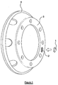
- a detection device 1 is illustrated.
- the detection device 1 fits into a recess 2 that has in machined into a wheel rim 4 of a wheel.
- the recess 2 depth is selected such that a back face of the detection unit is accurately aligned with the back face of the wheel rim 4.
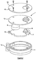
- the detection device 1 is illustrated.
- the detection device 1 is provided with a detector 6 that presses against the wheel hub and senses the contact with the wheel hub.
- the detector 6 is mounted on a printed circuit board (PCB) 7, along with transmission circuitry 8.
- Radio Frequency (RF) transmission is suitable, although that it will be appreciated that any type of wireless transmission is suitable.
- the PCB 7 also has a docking connector 15 that protrudes into a docking area 14, allowing the unit to be docked to a receiving unit.
- the docking area is a shape feature that protrudes and allows it to be fitted to a corresponding shape feature of the recess 2, thereby preventing rotation of the detection unit 1 in the recess 2 during rotation of the wheel.
- the PCB 7 is mounted in a housing 11 with a seal 13 placed over it.
- a back plate 12 closes the PCB 7 in the housing 11 using screws 16.
- the seal 13 provides hermetic sealing and allows for movement of the detector 6.
- the detector 6 of the detection device 1 abuts the wheel hub 5 as it is located in the recess machined into the wheel rim 4.
- the detector 6 passes through an opening in the back plate 12 but is still protected by the seal 13. Because the recess 2 is accurately machined, the detection device 1 is located accurately and when the wheel is located securely to the wheel hub, the detector 6 signals that the wheel is located securely. If the wheel rim 4 starts to loosen from the wheel hub, this is detected by the detector 6, which in turn instructs the RF circuitry to send an alarm signal.
- Figure 4 shows an exemplary embodiment in which a detector 6 is a mechanical switch having a biasing means such as a spring to bias the detector towards the wheel hub 5.
- a biasing means such as a spring
- FIG 4A shows the detector 6 in a closed position in which the wheel is secured to the wheel hub 5.
- the detector 6 comprises a switch actuator 17, a coil spring 18 in contact with the switch actuator, and an actuator spring 19 that is biased towards the PCB 7.
- the PCB is provided with switch terminals 20.
- the switch actuator 17 is pressed down, thereby making contact with the switch terminals 20 and closing the circuit.
- the coil spring pushed the actuator switch 17 towards the wheel hub, thereby breaking the electrical contact with the switch terminals 20. This is detected by a processor located on the PCB 7, and the transmission circuitry 8 sends an alarm signal.
- each detection device 1 on a particular vehicle will have some way of identifying itself when an alarm signal is sent. This may be, for example, transmitting at different frequencies or using an identifying header in an alarm signal.
- the processor in the PCB 7 may also be arranged to monitor battery life and send a different alarm signal in the event that battery life becomes low.
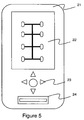
- the receiver unit 21 is used to programme the detection device 1 associated with each wheel. As mentioned above, each detection device 1 is provided with a docking area 14.
- the receiver unit 21 comprises a docking station 24 that is connectable using the docking area 14 to the detection device 1.
- a display 22 and navigation keys 23 are provided to show information to a user of the receiver unit and to allow the user to enter data to programme the detection device 1. This allows, for example, a user to select which wheel the detection device 1 will be fitted to, and to programme the detection device 1 to identify itself with an identifier associated with that wheel.
- the receiver unit 21 is used to alert the driver to wheels at risk of becoming loose. If a detection device transmits and alarm signal, the display 22 of the receiver unit 21 shows on the display 22 which wheel is coming loose, and an alarm (for example an audible alarm) may be used to alert the driver. Once the driver is alerted, he can stop the vehicle and attend to the wheel.
- an alarm for example an audible alarm
- Figure 6 is a flow diagram illustrating the fitting an operation of a detection device 1, which is not part of the invention. The following numbering corresponds with the numbering of Figure 6 .
- the entire back cover of the detection device acts as a detector.
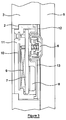
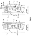
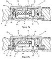
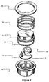
- Figures 7 and 8 show cross-sectional and exploded views of the device according to the further embodiment.
- the device 25 has an external case 26 and an internal case 27.
- the external case 26 locates in a recess in the wheel rim 4, and the internal case 27 abuts against the wheel hub of an axle to which the wheel is attached (note that the device could be used the other way round, so that the internal case abuts against the wheel rim rather than the wheel hub. However, this is not preferred as it would require some movement of the external case relative to the wheel rim).
- An O-ring seal 28 is located between the internal case 27 and the external case 26 to prevent moisture from entering the interior of the external case 26.
- a return spring 29 is also disposed between the internal case 26 and the external case 27, arranged to bias the internal case 27 away from the external case.
- the device also comprises a PCB 29, a battery 30 for powering the device, and a detector 31 that presses against a switch plate 32 located on an inner surface of the internal case 27.
- the PCB 29 and detector 31 are all mounted in potting epoxy 33.
- the detector 31 is fixed relative to the external case 26, and presses against a switching plate 32 that is fixed relative to the internal case 27. The detector 31 will therefore detect any movement of the internal case 27 relative to the external case 26.
- a retainer plate 34 is also provided for locating between the external case 26 and the wheel hub.
- the internal case 27 can pass through the retainer plate 34.
- the detector 31 may operate in any of several ways, and may a switch such as a mechanical switch, a magnetic switch, a capacitive switch, a pressure sensitive switch or a resistive switch.
- the detector is illustrated in Figures 7 and 8 as being a mechanical actuator that makes an electrical circuit. The actuator is biased towards the wheel hub, so that when the device is in the configuration shown in Figure 7b , the electrical circuit is broken, thereby triggering the alarm signal.
- the main advantage of the further embodiment is that it is more robust; there is no need for a flexible seal 13, as with the first embodiment.
- the device according to the further embodiment otherwise operates in a very similar way to, and is compatible with, the device described in the first embodiment.
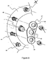
- FIG. 9 The embodiment showing a mounting arrangement according to the invention, is shown in Figure 9 .
- the embodiments described above describe the detection device 1 being mounted in a recess 2 of a wheel rim 4.
- the embodiment shown in Figure 9 does not require a recess to be machined in the wheel rim.
- a wheel rim 35 is mounted to a wheel hub using wheel hub studs 40, 41 and locking nuts 36.
- a mounting plate 37 has two apertures 38, 39 which are spaced apart so as to allow them to fit over two adjacent wheel hub studs 40, 41.
- the mounting plate 37 further comprises an attachment point 42 to which a detection device 1 can be attached.
- the detection device abuts the wheel rim and, indirectly, the wheel hub. If the nuts start to loosen, and the wheel rim 4 moves away from the wheel hub, then the detection device will no longer firmly abut the wheel rim 4, and so indirectly will no longer firmly abut the wheel hub, and so the driver can be alerted that the wheel rim is moving away from the wheel hub and the same way as described above.
- this embodiment is otherwise compatible with the above-described embodiments.
- the invention differs substantially from the prior art in that it provides apparatus and a method for detecting loss of the wheel from the wheel hub, rather than detecting loosening of the wheel nuts or attempting to prevent loosening of the wheel nuts. This allows the driver of the vehicle to be alerted to a potential problem during a journey, even where the problem was not evident before the start of the journey.
Claims (10)
- Dispositif (1) de détection de perte de roue d'un véhicule pendant que le véhicule roule, le dispositif comprenant :un boîtier (26) configuré pour un montage, à l'usage, du dispositif sur une roue (35) de manière que le dispositif soit placé contre un moyeu de roue (5) d'un essieu auquel la roue est rattachée ;un détecteur (31) destiné à détecter une proximité du dispositif vis-à-vis du moyeu de roue ;un émetteur (8) destiné à envoyer un signal d'alarme au cas où le détecteur détecte que le dispositif n'est plus à proximité du moyeu de roue, caractérisé en ce que la roue est disposée entre le dispositif et le moyeu de roue ; etle dispositif est couplé à une plaque de montage (35) comprenant deux ouvertures (38, 39) agencées pour loger sur deux goujons de moyeu de roue (40, 41) adjacents de manière que, à l'usage, le dispositif soit placé contre la jante de la roue (35) et soit ainsi indirectement placé contre le moyeu de roue (5).
- Dispositif selon la revendication 1, dans lequel le détecteur (31) est choisi parmi un contacteur mécanique, un contacteur magnétique, un commutateur capacitif, un contacteur sensible à la pression et un commutateur résistif.
- Dispositif selon la revendication 1, dans lequel le détecteur (31) comprend un actionneur mécanique (17) qui crée un circuit électrique, l'actionneur étant contraint par un moyen de contrainte (19) vers le moyeu de roue (5), dans lequel, au cas où le dispositif (1) n'est plus à proximité du moyeu de roue, l'action du moyen de contrainte sur l'actionneur rompt le circuit électrique, en déclenchant ainsi le signal d'alarme.
- Dispositif selon la revendication 1, 2 ou 3, comprenant en outre un processeur et une mémoire, la mémoire étant agencée pour stocker un identifiant relatif au dispositif, dans lequel le signal d'alarme comporte l'identifiant.
- Dispositif selon la revendication 4, comprenant en outre un port de connexion (14) destiné à la connexion du dispositif à une unité réceptrice (21), le port de connexion étant agencé pour recevoir l'identifiant en provenance de l'unité réceptrice avant de stocker l'identifiant dans la mémoire.
- Dispositif selon l'une quelconque des revendications 1 à 5, comprenant en outre un logement intérieur (27) disposé à l'intérieur du boîtier (26) et déplaçable par rapport au boîtier, dans lequel le logement intérieur est contraint à l'écart du boîtier, et le détecteur (31) est agencé pour détecter un mouvement du logement intérieur par rapport au boîtier.
- Système de détection de perte de roue permettant de détecter la perte d'une roue pendant que le véhicule roule, le système étant caractérisé par :une plaque de montage (37) comprenant deux ouvertures (38, 39) agencées pour loger sur deux goujons de moyeu de roue (40, 41) adjacents ;un dispositif de détection (1) couplé à la plaque de montage de manière que, à l'usage, le dispositif soit placé contre une jante de la roue (35) adjacente à un moyeu de roue auquel la roue est rattachée, la roue étant disposée entre le moyeu de roue et le dispositif de détection (1), le dispositif de détection (1) comprenant un détecteur (31) destiné à détecter une proximité du dispositif vis-à-vis du moyeu de roue et un émetteur (8) destiné à envoyer un signal d'alarme au cas où le détecteur (31) détecte que le dispositif (1) n'est plus à proximité du moyeu de roue ;une unité de réception (21) comprenant un récepteur destiné à recevoir le signal d'alarme en provenance du dispositif de détection, et un moyen permettant d'avertir un conducteur d'un véhicule en cas de réception d'un signal d'alarme.
- Système de détection de perte de roue selon la revendication 7, dans lequel le signal d'alarme comprend un identifiant de dispositif associé à une roue (35) du véhicule, et l'unité de réception (21) comprend un moyen permettant d'avertir le conducteur de l'identité de la roue associée.
- Système de détection de perte de roue selon la revendication 7 ou 8, dans lequel le détecteur (31) est choisi parmi l'un d'un contacteur mécanique, un contacteur magnétique, un commutateur capacitif, un contacteur sensible à la pression et un commutateur résistif.
- Procédé d'installation d'un dispositif de détection de perte de roue, le procédé étant caractérisé par :le montage d'un dispositif de détection de perte de roue (1) sur une jante de roue (35), le dispositif de détection de perte de roue étant couplé à une plaque de montage de manière que, à l'usage, le dispositif soit placé contre la jante de la roue, et dans lequel la plaque de montage (37) est rattachée au moyeu de roue au moyen de deux ouvertures (38, 39) agencées pour loger sur deux goujons de moyeu de roue (40, 41) adjacents ;le dispositif de détection de perte de roue (1) comprenant un détecteur (31) destiné à détecter une proximité du dispositif (1) vis-à-vis d'un moyeu de roue et un émetteur (8) destiné à envoyer un signal d'alarme au cas où le détecteur détecte que le dispositif n'est plus à proximité du moyeu de roue ; l'installation de la roue sur le moyeu de roue de manière que la roue (35) soit disposée entre le moyeu de roue et le dispositif de détection (1).
Applications Claiming Priority (2)
| Application Number | Priority Date | Filing Date | Title |
|---|---|---|---|
| GB1005289A GB2474530A (en) | 2010-03-30 | 2010-03-30 | Wheel loss detection |
| PCT/GB2011/050583 WO2011121334A1 (fr) | 2010-03-30 | 2011-03-23 | Détection de perte de roue |
Publications (2)
| Publication Number | Publication Date |
|---|---|
| EP2552711A1 EP2552711A1 (fr) | 2013-02-06 |
| EP2552711B1 true EP2552711B1 (fr) | 2016-04-27 |
Family
ID=42228557
Family Applications (1)
| Application Number | Title | Priority Date | Filing Date |
|---|---|---|---|
| EP11712310.9A Active EP2552711B1 (fr) | 2010-03-30 | 2011-03-23 | Détection de perte de roue |
Country Status (6)
| Country | Link |
|---|---|
| US (1) | US9067527B2 (fr) |
| EP (1) | EP2552711B1 (fr) |
| JP (1) | JP2013523519A (fr) |
| ES (1) | ES2579629T3 (fr) |
| GB (1) | GB2474530A (fr) |
| WO (1) | WO2011121334A1 (fr) |
Families Citing this family (9)
| Publication number | Priority date | Publication date | Assignee | Title |
|---|---|---|---|---|
| AU2011235942B2 (en) * | 2011-10-11 | 2015-01-22 | Nicholas Charles Dooner | Safetytrim nut locking device |
| BR112015008097A2 (pt) * | 2012-10-10 | 2017-07-04 | Innotech Safety Solutions Inc | sistema de aspecto de detecção de roubo e aspecto de detecção de perda de roda e dispositivo para veículos |
| GB2531377B (en) * | 2015-05-14 | 2017-02-01 | Wheely-Safe Ltd | Wheel loosening sensor |
| GB2542136A (en) * | 2015-09-08 | 2017-03-15 | Wheely-Safe Ltd | Wheel loosening sensor |
| GB201519223D0 (en) * | 2015-10-30 | 2015-12-16 | Wheely Safe Ltd | Wheel sensor cooling |
| GB2550389A (en) * | 2016-05-18 | 2017-11-22 | Indespension Ltd | A detachment alert device |
| US10286923B1 (en) * | 2017-11-15 | 2019-05-14 | Ford Global Technologies, Llc | Tire vibration and loose wheel detection |
| WO2023007715A1 (fr) * | 2021-07-30 | 2023-02-02 | 太平洋工業株式会社 | Système de détection de chute d'élément de fixation de roue |
| WO2023007718A1 (fr) * | 2021-07-30 | 2023-02-02 | 太平洋工業株式会社 | Dispositif de détection de desserrement d'élément de fixation de roue |
Family Cites Families (13)
| Publication number | Priority date | Publication date | Assignee | Title |
|---|---|---|---|---|
| IT1260474B (it) | 1992-05-28 | 1996-04-09 | Catalizzatore metallico supportato per l'idrogenazione di composti organici e suo procedimento di preparazione | |
| JP2570848Y2 (ja) * | 1993-02-22 | 1998-05-13 | 株式会社東海理化電機製作所 | タイヤの異常検出装置 |
| US5552759A (en) * | 1994-11-02 | 1996-09-03 | Stoyka; David S. | Electronic system for detecting vehicle wheel theft |
| AU2453701A (en) * | 1999-12-22 | 2001-07-03 | Wabash Technology Corporation | Vehicle axle end wheel speed sensor |
| US7012511B2 (en) * | 2003-10-20 | 2006-03-14 | Arvinmeritor Technology, Llc | Loose wheel indicator |
| JP2005329907A (ja) * | 2004-05-21 | 2005-12-02 | Denso Corp | 車輪脱落検出装置 |
| FR2874271B1 (fr) * | 2004-08-10 | 2006-11-24 | Siemens Vdo Automotive Sas | Procede et dispositif de detection de la desolidarisation d'un capteur par rapport a un vehicule sur lequel est monte le dit capteur |
| US7873449B2 (en) | 2007-03-29 | 2011-01-18 | Ford Global Technologies | Vehicle safety system with advanced tire monitoring |
| US7994901B2 (en) * | 2008-02-18 | 2011-08-09 | Tag Blue L.L.C. | Lug stud and lug nut monitoring system, method, and components therefor |
| US20090284357A1 (en) * | 2008-05-16 | 2009-11-19 | Jesse Ortega | Vehicle wheel security system |
| DE102009020359A1 (de) * | 2009-04-30 | 2010-11-04 | Iav Gmbh Ingenieurgesellschaft Auto Und Verkehr | Verfahren und Vorrichtung zur Stromregelung eines ein mechanisches Schließelement umfassenden Ventils |
| DE102009020358A1 (de) | 2009-05-07 | 2009-12-24 | Daimler Ag | Einrichtung und Verfahren zum Erkennen einer Fehlmontage eines Rades an einem Kraftwagen |
| US8525653B1 (en) * | 2010-04-29 | 2013-09-03 | Wayne A. Bing | Anti-theft system for wheels and rims |
-
2010
- 2010-03-30 GB GB1005289A patent/GB2474530A/en not_active Withdrawn
-
2011
- 2011-03-23 EP EP11712310.9A patent/EP2552711B1/fr active Active
- 2011-03-23 JP JP2013501940A patent/JP2013523519A/ja active Pending
- 2011-03-23 ES ES11712310.9T patent/ES2579629T3/es active Active
- 2011-03-23 US US13/638,064 patent/US9067527B2/en active Active
- 2011-03-23 WO PCT/GB2011/050583 patent/WO2011121334A1/fr active Application Filing
Also Published As
| Publication number | Publication date |
|---|---|
| EP2552711A1 (fr) | 2013-02-06 |
| ES2579629T3 (es) | 2016-08-12 |
| GB2474530A (en) | 2011-04-20 |
| JP2013523519A (ja) | 2013-06-17 |
| US9067527B2 (en) | 2015-06-30 |
| GB201005289D0 (en) | 2010-05-12 |
| WO2011121334A1 (fr) | 2011-10-06 |
| US20130088346A1 (en) | 2013-04-11 |
Similar Documents
| Publication | Publication Date | Title |
|---|---|---|
| EP2552711B1 (fr) | Détection de perte de roue | |
| US9070271B2 (en) | Apparatus and method for detecting unauthorized removal of asset tracking device | |
| CN108001112B (zh) | 车轮紧固件报警器 | |
| CN106715930B (zh) | 车轮螺母或轮轴螺母、车辆中车轮螺母或轮轴螺母的控制装置及设有其的车辆 | |
| US5717135A (en) | Tire pressure monitoring system utilizing a pressure activated transducer and sensor | |
| US9389149B2 (en) | Wheel loss detection aspect and theft detection aspect system and device for vehicles | |
| US7535342B2 (en) | Radio communication module to be installed on vehicular license plate | |
| US20050083186A1 (en) | Loose wheel indicator | |
| US20080094191A1 (en) | Display Device for Displaying a Theft Attempt and Method for Operating Said Device | |
| WO2000007158A1 (fr) | Dispositif d'alerte a fonction diagnostique autonome | |
| US20070080802A1 (en) | Tamper & intrusion detection device | |
| KR20210042400A (ko) | 패스너 | |
| US20140159889A1 (en) | Transmitter apparatus for transmitting tire information, and tire information monitoring system | |
| EP3294572B1 (fr) | Capteur de desserrage de roue | |
| KR101673697B1 (ko) | 차량용 통합 루프 안테나 모듈을 통한 보안 침입 경보 시스템 | |
| US7187944B2 (en) | Onboard cell phone automatic dialing device | |
| CN116848566A (zh) | 车轮紧固件报警器 | |
| GB2596896A (en) | A sensor assembly | |
| TH64167A (th) | ระบบสัญญาณกันขโมยชนิดร้องขอความช่วยเหลือแบบโต้ตอบ | |
| KR20000020317A (ko) | 차량의 휠 미체결 경보장치 | |
| JP2005316695A (ja) | 機器の取り外し検出装置 |
Legal Events
| Date | Code | Title | Description |
|---|---|---|---|
| PUAI | Public reference made under article 153(3) epc to a published international application that has entered the european phase |
Free format text: ORIGINAL CODE: 0009012 |
|
| 17P | Request for examination filed |
Effective date: 20121017 |
|
| AK | Designated contracting states |
Kind code of ref document: A1 Designated state(s): AL AT BE BG CH CY CZ DE DK EE ES FI FR GB GR HR HU IE IS IT LI LT LU LV MC MK MT NL NO PL PT RO RS SE SI SK SM TR |
|
| DAX | Request for extension of the european patent (deleted) | ||
| 17Q | First examination report despatched |
Effective date: 20140205 |
|
| RIC1 | Information provided on ipc code assigned before grant |
Ipc: B60B 3/16 20060101AFI20140919BHEP Ipc: B60Q 1/00 20060101ALI20140919BHEP Ipc: B60R 25/10 20130101ALI20140919BHEP |
|
| GRAP | Despatch of communication of intention to grant a patent |
Free format text: ORIGINAL CODE: EPIDOSNIGR1 |
|
| RIN1 | Information on inventor provided before grant (corrected) |
Inventor name: BROADFIELD, GARY |
|
| INTG | Intention to grant announced |
Effective date: 20141110 |
|
| INTG | Intention to grant announced |
Effective date: 20160119 |
|
| GRAS | Grant fee paid |
Free format text: ORIGINAL CODE: EPIDOSNIGR3 |
|
| GRAA | (expected) grant |
Free format text: ORIGINAL CODE: 0009210 |
|
| AK | Designated contracting states |
Kind code of ref document: B1 Designated state(s): AL AT BE BG CH CY CZ DE DK EE ES FI FR GB GR HR HU IE IS IT LI LT LU LV MC MK MT NL NO PL PT RO RS SE SI SK SM TR |
|
| REG | Reference to a national code |
Ref country code: GB Ref legal event code: FG4D |
|
| REG | Reference to a national code |
Ref country code: CH Ref legal event code: EP |
|
| REG | Reference to a national code |
Ref country code: AT Ref legal event code: REF Ref document number: 794305 Country of ref document: AT Kind code of ref document: T Effective date: 20160515 |
|
| REG | Reference to a national code |
Ref country code: IE Ref legal event code: FG4D |
|
| REG | Reference to a national code |
Ref country code: DE Ref legal event code: R096 Ref document number: 602011025900 Country of ref document: DE |
|
| REG | Reference to a national code |
Ref country code: ES Ref legal event code: FG2A Ref document number: 2579629 Country of ref document: ES Kind code of ref document: T3 Effective date: 20160812 |
|
| REG | Reference to a national code |
Ref country code: LT Ref legal event code: MG4D |
|
| REG | Reference to a national code |
Ref country code: NL Ref legal event code: MP Effective date: 20160427 |
|
| REG | Reference to a national code |
Ref country code: AT Ref legal event code: MK05 Ref document number: 794305 Country of ref document: AT Kind code of ref document: T Effective date: 20160427 |
|
| PG25 | Lapsed in a contracting state [announced via postgrant information from national office to epo] |
Ref country code: NL Free format text: LAPSE BECAUSE OF FAILURE TO SUBMIT A TRANSLATION OF THE DESCRIPTION OR TO PAY THE FEE WITHIN THE PRESCRIBED TIME-LIMIT Effective date: 20160427 |
|
| PG25 | Lapsed in a contracting state [announced via postgrant information from national office to epo] |
Ref country code: PL Free format text: LAPSE BECAUSE OF FAILURE TO SUBMIT A TRANSLATION OF THE DESCRIPTION OR TO PAY THE FEE WITHIN THE PRESCRIBED TIME-LIMIT Effective date: 20160427 Ref country code: NO Free format text: LAPSE BECAUSE OF FAILURE TO SUBMIT A TRANSLATION OF THE DESCRIPTION OR TO PAY THE FEE WITHIN THE PRESCRIBED TIME-LIMIT Effective date: 20160727 Ref country code: LT Free format text: LAPSE BECAUSE OF FAILURE TO SUBMIT A TRANSLATION OF THE DESCRIPTION OR TO PAY THE FEE WITHIN THE PRESCRIBED TIME-LIMIT Effective date: 20160427 Ref country code: FI Free format text: LAPSE BECAUSE OF FAILURE TO SUBMIT A TRANSLATION OF THE DESCRIPTION OR TO PAY THE FEE WITHIN THE PRESCRIBED TIME-LIMIT Effective date: 20160427 |
|
| PG25 | Lapsed in a contracting state [announced via postgrant information from national office to epo] |
Ref country code: PT Free format text: LAPSE BECAUSE OF FAILURE TO SUBMIT A TRANSLATION OF THE DESCRIPTION OR TO PAY THE FEE WITHIN THE PRESCRIBED TIME-LIMIT Effective date: 20160829 Ref country code: RS Free format text: LAPSE BECAUSE OF FAILURE TO SUBMIT A TRANSLATION OF THE DESCRIPTION OR TO PAY THE FEE WITHIN THE PRESCRIBED TIME-LIMIT Effective date: 20160427 Ref country code: AT Free format text: LAPSE BECAUSE OF FAILURE TO SUBMIT A TRANSLATION OF THE DESCRIPTION OR TO PAY THE FEE WITHIN THE PRESCRIBED TIME-LIMIT Effective date: 20160427 Ref country code: GR Free format text: LAPSE BECAUSE OF FAILURE TO SUBMIT A TRANSLATION OF THE DESCRIPTION OR TO PAY THE FEE WITHIN THE PRESCRIBED TIME-LIMIT Effective date: 20160728 Ref country code: HR Free format text: LAPSE BECAUSE OF FAILURE TO SUBMIT A TRANSLATION OF THE DESCRIPTION OR TO PAY THE FEE WITHIN THE PRESCRIBED TIME-LIMIT Effective date: 20160427 Ref country code: LV Free format text: LAPSE BECAUSE OF FAILURE TO SUBMIT A TRANSLATION OF THE DESCRIPTION OR TO PAY THE FEE WITHIN THE PRESCRIBED TIME-LIMIT Effective date: 20160427 Ref country code: SE Free format text: LAPSE BECAUSE OF FAILURE TO SUBMIT A TRANSLATION OF THE DESCRIPTION OR TO PAY THE FEE WITHIN THE PRESCRIBED TIME-LIMIT Effective date: 20160427 |
|
| PG25 | Lapsed in a contracting state [announced via postgrant information from national office to epo] |
Ref country code: BE Free format text: LAPSE BECAUSE OF FAILURE TO SUBMIT A TRANSLATION OF THE DESCRIPTION OR TO PAY THE FEE WITHIN THE PRESCRIBED TIME-LIMIT Effective date: 20160427 |
|
| REG | Reference to a national code |
Ref country code: DE Ref legal event code: R097 Ref document number: 602011025900 Country of ref document: DE |
|
| PG25 | Lapsed in a contracting state [announced via postgrant information from national office to epo] |
Ref country code: CZ Free format text: LAPSE BECAUSE OF FAILURE TO SUBMIT A TRANSLATION OF THE DESCRIPTION OR TO PAY THE FEE WITHIN THE PRESCRIBED TIME-LIMIT Effective date: 20160427 Ref country code: RO Free format text: LAPSE BECAUSE OF FAILURE TO SUBMIT A TRANSLATION OF THE DESCRIPTION OR TO PAY THE FEE WITHIN THE PRESCRIBED TIME-LIMIT Effective date: 20160427 Ref country code: DK Free format text: LAPSE BECAUSE OF FAILURE TO SUBMIT A TRANSLATION OF THE DESCRIPTION OR TO PAY THE FEE WITHIN THE PRESCRIBED TIME-LIMIT Effective date: 20160427 Ref country code: SK Free format text: LAPSE BECAUSE OF FAILURE TO SUBMIT A TRANSLATION OF THE DESCRIPTION OR TO PAY THE FEE WITHIN THE PRESCRIBED TIME-LIMIT Effective date: 20160427 Ref country code: EE Free format text: LAPSE BECAUSE OF FAILURE TO SUBMIT A TRANSLATION OF THE DESCRIPTION OR TO PAY THE FEE WITHIN THE PRESCRIBED TIME-LIMIT Effective date: 20160427 |
|
| PG25 | Lapsed in a contracting state [announced via postgrant information from national office to epo] |
Ref country code: SM Free format text: LAPSE BECAUSE OF FAILURE TO SUBMIT A TRANSLATION OF THE DESCRIPTION OR TO PAY THE FEE WITHIN THE PRESCRIBED TIME-LIMIT Effective date: 20160427 |
|
| PLBE | No opposition filed within time limit |
Free format text: ORIGINAL CODE: 0009261 |
|
| STAA | Information on the status of an ep patent application or granted ep patent |
Free format text: STATUS: NO OPPOSITION FILED WITHIN TIME LIMIT |
|
| REG | Reference to a national code |
Ref country code: FR Ref legal event code: PLFP Year of fee payment: 7 |
|
| 26N | No opposition filed |
Effective date: 20170130 |
|
| PG25 | Lapsed in a contracting state [announced via postgrant information from national office to epo] |
Ref country code: SI Free format text: LAPSE BECAUSE OF FAILURE TO SUBMIT A TRANSLATION OF THE DESCRIPTION OR TO PAY THE FEE WITHIN THE PRESCRIBED TIME-LIMIT Effective date: 20160427 |
|
| REG | Reference to a national code |
Ref country code: CH Ref legal event code: PL |
|
| PG25 | Lapsed in a contracting state [announced via postgrant information from national office to epo] |
Ref country code: MC Free format text: LAPSE BECAUSE OF FAILURE TO SUBMIT A TRANSLATION OF THE DESCRIPTION OR TO PAY THE FEE WITHIN THE PRESCRIBED TIME-LIMIT Effective date: 20160427 |
|
| REG | Reference to a national code |
Ref country code: IE Ref legal event code: MM4A |
|
| PG25 | Lapsed in a contracting state [announced via postgrant information from national office to epo] |
Ref country code: LU Free format text: LAPSE BECAUSE OF NON-PAYMENT OF DUE FEES Effective date: 20170323 |
|
| PG25 | Lapsed in a contracting state [announced via postgrant information from national office to epo] |
Ref country code: LI Free format text: LAPSE BECAUSE OF NON-PAYMENT OF DUE FEES Effective date: 20170331 Ref country code: IE Free format text: LAPSE BECAUSE OF NON-PAYMENT OF DUE FEES Effective date: 20170323 Ref country code: CH Free format text: LAPSE BECAUSE OF NON-PAYMENT OF DUE FEES Effective date: 20170331 |
|
| REG | Reference to a national code |
Ref country code: FR Ref legal event code: PLFP Year of fee payment: 8 |
|
| PG25 | Lapsed in a contracting state [announced via postgrant information from national office to epo] |
Ref country code: MT Free format text: LAPSE BECAUSE OF NON-PAYMENT OF DUE FEES Effective date: 20170323 |
|
| PG25 | Lapsed in a contracting state [announced via postgrant information from national office to epo] |
Ref country code: AL Free format text: LAPSE BECAUSE OF FAILURE TO SUBMIT A TRANSLATION OF THE DESCRIPTION OR TO PAY THE FEE WITHIN THE PRESCRIBED TIME-LIMIT Effective date: 20160427 |
|
| PG25 | Lapsed in a contracting state [announced via postgrant information from national office to epo] |
Ref country code: HU Free format text: LAPSE BECAUSE OF FAILURE TO SUBMIT A TRANSLATION OF THE DESCRIPTION OR TO PAY THE FEE WITHIN THE PRESCRIBED TIME-LIMIT; INVALID AB INITIO Effective date: 20110323 |
|
| PG25 | Lapsed in a contracting state [announced via postgrant information from national office to epo] |
Ref country code: BG Free format text: LAPSE BECAUSE OF FAILURE TO SUBMIT A TRANSLATION OF THE DESCRIPTION OR TO PAY THE FEE WITHIN THE PRESCRIBED TIME-LIMIT Effective date: 20160427 |
|
| PG25 | Lapsed in a contracting state [announced via postgrant information from national office to epo] |
Ref country code: CY Free format text: LAPSE BECAUSE OF NON-PAYMENT OF DUE FEES Effective date: 20160427 |
|
| PG25 | Lapsed in a contracting state [announced via postgrant information from national office to epo] |
Ref country code: MK Free format text: LAPSE BECAUSE OF FAILURE TO SUBMIT A TRANSLATION OF THE DESCRIPTION OR TO PAY THE FEE WITHIN THE PRESCRIBED TIME-LIMIT Effective date: 20160427 |
|
| PG25 | Lapsed in a contracting state [announced via postgrant information from national office to epo] |
Ref country code: TR Free format text: LAPSE BECAUSE OF FAILURE TO SUBMIT A TRANSLATION OF THE DESCRIPTION OR TO PAY THE FEE WITHIN THE PRESCRIBED TIME-LIMIT Effective date: 20160427 |
|
| PG25 | Lapsed in a contracting state [announced via postgrant information from national office to epo] |
Ref country code: IS Free format text: LAPSE BECAUSE OF FAILURE TO SUBMIT A TRANSLATION OF THE DESCRIPTION OR TO PAY THE FEE WITHIN THE PRESCRIBED TIME-LIMIT Effective date: 20160827 |
|
| PGFP | Annual fee paid to national office [announced via postgrant information from national office to epo] |
Ref country code: FR Payment date: 20230327 Year of fee payment: 13 |
|
| PGFP | Annual fee paid to national office [announced via postgrant information from national office to epo] |
Ref country code: IT Payment date: 20230328 Year of fee payment: 13 Ref country code: ES Payment date: 20230529 Year of fee payment: 13 |
|
| P01 | Opt-out of the competence of the unified patent court (upc) registered |
Effective date: 20230918 |
|
| PGFP | Annual fee paid to national office [announced via postgrant information from national office to epo] |
Ref country code: DE Payment date: 20240320 Year of fee payment: 14 Ref country code: GB Payment date: 20240320 Year of fee payment: 14 |