EP2552519B1 - Ensemble tige de piston pour dispositif d'administration de médicament - Google Patents
Ensemble tige de piston pour dispositif d'administration de médicament Download PDFInfo
- Publication number
- EP2552519B1 EP2552519B1 EP11711562.6A EP11711562A EP2552519B1 EP 2552519 B1 EP2552519 B1 EP 2552519B1 EP 11711562 A EP11711562 A EP 11711562A EP 2552519 B1 EP2552519 B1 EP 2552519B1
- Authority
- EP
- European Patent Office
- Prior art keywords
- piston rod
- piston
- adjusting member
- rod assembly
- cartridge
- Prior art date
- Legal status (The legal status is an assumption and is not a legal conclusion. Google has not performed a legal analysis and makes no representation as to the accuracy of the status listed.)
- Active
Links
Images


Classifications
-
- A—HUMAN NECESSITIES
- A61—MEDICAL OR VETERINARY SCIENCE; HYGIENE
- A61M—DEVICES FOR INTRODUCING MEDIA INTO, OR ONTO, THE BODY; DEVICES FOR TRANSDUCING BODY MEDIA OR FOR TAKING MEDIA FROM THE BODY; DEVICES FOR PRODUCING OR ENDING SLEEP OR STUPOR
- A61M5/00—Devices for bringing media into the body in a subcutaneous, intra-vascular or intramuscular way; Accessories therefor, e.g. filling or cleaning devices, arm-rests
- A61M5/178—Syringes
- A61M5/31—Details
- A61M5/315—Pistons; Piston-rods; Guiding, blocking or restricting the movement of the rod or piston; Appliances on the rod for facilitating dosing ; Dosing mechanisms
- A61M5/31511—Piston or piston-rod constructions, e.g. connection of piston with piston-rod
- A61M5/31515—Connection of piston with piston rod
-
- A—HUMAN NECESSITIES
- A61—MEDICAL OR VETERINARY SCIENCE; HYGIENE
- A61M—DEVICES FOR INTRODUCING MEDIA INTO, OR ONTO, THE BODY; DEVICES FOR TRANSDUCING BODY MEDIA OR FOR TAKING MEDIA FROM THE BODY; DEVICES FOR PRODUCING OR ENDING SLEEP OR STUPOR
- A61M5/00—Devices for bringing media into the body in a subcutaneous, intra-vascular or intramuscular way; Accessories therefor, e.g. filling or cleaning devices, arm-rests
- A61M5/178—Syringes
- A61M5/31—Details
- A61M5/315—Pistons; Piston-rods; Guiding, blocking or restricting the movement of the rod or piston; Appliances on the rod for facilitating dosing ; Dosing mechanisms
- A61M5/31533—Dosing mechanisms, i.e. setting a dose
- A61M5/31545—Setting modes for dosing
- A61M5/31548—Mechanically operated dose setting member
- A61M5/31555—Mechanically operated dose setting member by purely axial movement of dose setting member, e.g. during setting or filling of a syringe
-
- A—HUMAN NECESSITIES
- A61—MEDICAL OR VETERINARY SCIENCE; HYGIENE
- A61M—DEVICES FOR INTRODUCING MEDIA INTO, OR ONTO, THE BODY; DEVICES FOR TRANSDUCING BODY MEDIA OR FOR TAKING MEDIA FROM THE BODY; DEVICES FOR PRODUCING OR ENDING SLEEP OR STUPOR
- A61M5/00—Devices for bringing media into the body in a subcutaneous, intra-vascular or intramuscular way; Accessories therefor, e.g. filling or cleaning devices, arm-rests
- A61M5/178—Syringes
- A61M5/31—Details
- A61M5/315—Pistons; Piston-rods; Guiding, blocking or restricting the movement of the rod or piston; Appliances on the rod for facilitating dosing ; Dosing mechanisms
- A61M5/31533—Dosing mechanisms, i.e. setting a dose
- A61M5/31545—Setting modes for dosing
- A61M5/31548—Mechanically operated dose setting member
- A61M5/3156—Mechanically operated dose setting member using volume steps only adjustable in discrete intervals, i.e. individually distinct intervals
-
- A—HUMAN NECESSITIES
- A61—MEDICAL OR VETERINARY SCIENCE; HYGIENE
- A61M—DEVICES FOR INTRODUCING MEDIA INTO, OR ONTO, THE BODY; DEVICES FOR TRANSDUCING BODY MEDIA OR FOR TAKING MEDIA FROM THE BODY; DEVICES FOR PRODUCING OR ENDING SLEEP OR STUPOR
- A61M5/00—Devices for bringing media into the body in a subcutaneous, intra-vascular or intramuscular way; Accessories therefor, e.g. filling or cleaning devices, arm-rests
- A61M5/178—Syringes
- A61M5/31—Details
- A61M5/315—Pistons; Piston-rods; Guiding, blocking or restricting the movement of the rod or piston; Appliances on the rod for facilitating dosing ; Dosing mechanisms
- A61M5/31565—Administration mechanisms, i.e. constructional features, modes of administering a dose
- A61M5/31576—Constructional features or modes of drive mechanisms for piston rods
- A61M5/31578—Constructional features or modes of drive mechanisms for piston rods based on axial translation, i.e. components directly operatively associated and axially moved with plunger rod
- A61M5/3158—Constructional features or modes of drive mechanisms for piston rods based on axial translation, i.e. components directly operatively associated and axially moved with plunger rod performed by axially moving actuator operated by user, e.g. an injection button
-
- A—HUMAN NECESSITIES
- A61—MEDICAL OR VETERINARY SCIENCE; HYGIENE
- A61M—DEVICES FOR INTRODUCING MEDIA INTO, OR ONTO, THE BODY; DEVICES FOR TRANSDUCING BODY MEDIA OR FOR TAKING MEDIA FROM THE BODY; DEVICES FOR PRODUCING OR ENDING SLEEP OR STUPOR
- A61M5/00—Devices for bringing media into the body in a subcutaneous, intra-vascular or intramuscular way; Accessories therefor, e.g. filling or cleaning devices, arm-rests
- A61M5/178—Syringes
- A61M5/24—Ampoule syringes, i.e. syringes with needle for use in combination with replaceable ampoules or carpules, e.g. automatic
- A61M2005/2403—Ampoule inserted into the ampoule holder
- A61M2005/2407—Ampoule inserted into the ampoule holder from the rear
-
- A—HUMAN NECESSITIES
- A61—MEDICAL OR VETERINARY SCIENCE; HYGIENE
- A61M—DEVICES FOR INTRODUCING MEDIA INTO, OR ONTO, THE BODY; DEVICES FOR TRANSDUCING BODY MEDIA OR FOR TAKING MEDIA FROM THE BODY; DEVICES FOR PRODUCING OR ENDING SLEEP OR STUPOR
- A61M5/00—Devices for bringing media into the body in a subcutaneous, intra-vascular or intramuscular way; Accessories therefor, e.g. filling or cleaning devices, arm-rests
- A61M5/178—Syringes
- A61M5/31—Details
- A61M5/315—Pistons; Piston-rods; Guiding, blocking or restricting the movement of the rod or piston; Appliances on the rod for facilitating dosing ; Dosing mechanisms
- A61M5/31511—Piston or piston-rod constructions, e.g. connection of piston with piston-rod
- A61M2005/3152—Piston or piston-rod constructions, e.g. connection of piston with piston-rod including gearings to multiply or attenuate the piston displacing force
-
- A—HUMAN NECESSITIES
- A61—MEDICAL OR VETERINARY SCIENCE; HYGIENE
- A61M—DEVICES FOR INTRODUCING MEDIA INTO, OR ONTO, THE BODY; DEVICES FOR TRANSDUCING BODY MEDIA OR FOR TAKING MEDIA FROM THE BODY; DEVICES FOR PRODUCING OR ENDING SLEEP OR STUPOR
- A61M2207/00—Methods of manufacture, assembly or production
-
- A—HUMAN NECESSITIES
- A61—MEDICAL OR VETERINARY SCIENCE; HYGIENE
- A61M—DEVICES FOR INTRODUCING MEDIA INTO, OR ONTO, THE BODY; DEVICES FOR TRANSDUCING BODY MEDIA OR FOR TAKING MEDIA FROM THE BODY; DEVICES FOR PRODUCING OR ENDING SLEEP OR STUPOR
- A61M5/00—Devices for bringing media into the body in a subcutaneous, intra-vascular or intramuscular way; Accessories therefor, e.g. filling or cleaning devices, arm-rests
- A61M5/178—Syringes
- A61M5/24—Ampoule syringes, i.e. syringes with needle for use in combination with replaceable ampoules or carpules, e.g. automatic
-
- A—HUMAN NECESSITIES
- A61—MEDICAL OR VETERINARY SCIENCE; HYGIENE
- A61M—DEVICES FOR INTRODUCING MEDIA INTO, OR ONTO, THE BODY; DEVICES FOR TRANSDUCING BODY MEDIA OR FOR TAKING MEDIA FROM THE BODY; DEVICES FOR PRODUCING OR ENDING SLEEP OR STUPOR
- A61M5/00—Devices for bringing media into the body in a subcutaneous, intra-vascular or intramuscular way; Accessories therefor, e.g. filling or cleaning devices, arm-rests
- A61M5/178—Syringes
- A61M5/31—Details
- A61M5/3146—Priming, e.g. purging, reducing backlash or clearance
-
- A—HUMAN NECESSITIES
- A61—MEDICAL OR VETERINARY SCIENCE; HYGIENE
- A61M—DEVICES FOR INTRODUCING MEDIA INTO, OR ONTO, THE BODY; DEVICES FOR TRANSDUCING BODY MEDIA OR FOR TAKING MEDIA FROM THE BODY; DEVICES FOR PRODUCING OR ENDING SLEEP OR STUPOR
- A61M5/00—Devices for bringing media into the body in a subcutaneous, intra-vascular or intramuscular way; Accessories therefor, e.g. filling or cleaning devices, arm-rests
- A61M5/178—Syringes
- A61M5/31—Details
- A61M5/315—Pistons; Piston-rods; Guiding, blocking or restricting the movement of the rod or piston; Appliances on the rod for facilitating dosing ; Dosing mechanisms
- A61M5/31511—Piston or piston-rod constructions, e.g. connection of piston with piston-rod
-
- Y—GENERAL TAGGING OF NEW TECHNOLOGICAL DEVELOPMENTS; GENERAL TAGGING OF CROSS-SECTIONAL TECHNOLOGIES SPANNING OVER SEVERAL SECTIONS OF THE IPC; TECHNICAL SUBJECTS COVERED BY FORMER USPC CROSS-REFERENCE ART COLLECTIONS [XRACs] AND DIGESTS
- Y10—TECHNICAL SUBJECTS COVERED BY FORMER USPC
- Y10T—TECHNICAL SUBJECTS COVERED BY FORMER US CLASSIFICATION
- Y10T29/00—Metal working
- Y10T29/49—Method of mechanical manufacture
- Y10T29/49826—Assembling or joining
Definitions
- the present invention relates to a piston rod assembly for a drug delivery device that allows a user to select single or multiple doses of an injectable medicinal product and to dispense and to deliver the set dose to a patient, preferably by way of injection.
- the present invention relates to such drug delivery devices that are handled by the patients themselves, such like pen-type injectors.
- Drug delivery devices allowing for multiple dosing of a required dosage of a liquid medicinal product, such as a liquid medicament, and further providing administration of the liquid to a patient, are as such well-known in the art. Generally, such devices have substantially the same purpose as that of an ordinary syringe.
- Drug delivery devices of this kind have to meet a number of user specific requirements. For instance in case of those with diabetes, many users will be physically infirm and may also have impaired vision. Therefore, these devices need to be robust in construction, yet easy to use, both in terms of the manipulation of the parts and understanding by a user of its operation. Further, the dose setting must be easy and unambiguous and where the device is to be disposable rather than reusable, the device should be inexpensive to manufacture and easy to dispose. In order to meet these requirements, the number of parts and steps required to assemble the device and an overall number of material types the device is made from have to be kept to a minimum.
- the medicinal product to be administered is provided in a cartridge that has a moveable piston or bung mechanically interacting with a piston rod of a drive mechanism of the drug delivery device.
- a certain amount of the medicinal fluid is expelled from the cartridge and may be administered to the patient by some kind of needle assembly being in fluid communication with the cartridge.
- the device In particular with disposable drug delivery devices, wherein the entire device is discarded after consumption of the medicament, the device is initially provided with a cartridge containing the medicament.
- Such disposable but also reusable drug delivery devices are assembled in a mass production process in which for instance two housing components of the drug delivery device receive a cartridge and a drive mechanism including the piston rod, respectively. Then, in a final step of assembly, the two pre-configured housing components or respective sub-assemblies are to be mutually interconnected.
- piston rod should not exert pressure to the plunger during assembly, which may otherwise result in a rather uncontrolled expelling of the medicament prior to a first use of the drug delivery device when a needle is attached.
- the components themselves, and their assembly is inevitably subject to certain geometric tolerances.
- the cartridge itself and in particular the position of the piston within the cartridge may vary.
- Document WO 2009/095332 A1 discloses a prefilled injection device incorporating an axial variable connection.
- Document US 2005/0177116 A1 discloses an injection device for injecting selectable amounts of a substance including an axially movable operating button which can be rotated in a resting position only.
- the piston rod assembly and the respective drug delivery device should be intuitive and easy in handling.
- a general compatibility of the piston rod assembly and of a respective drug delivery device with existing manufacturing processes is a further aim of the invention.
- the invention should be implementable with reasonable costs and expenditure.
- the invention as defined in the independent claims, provides a piston rod assembly for a drug delivery device which is adapted to become operably engaged with a piston of a cartridge that is filled with an injectable fluid, in particular with a medicament, such like insulin.
- the piston rod assembly is intended to become operably engaged with a drive mechanism of a drug delivery device allowing for setting a pre-defined dose and to induce an axial displacement on the piston rod in distal direction in order to move the piston of the cartridge in a respective direction for expelling a pre-defined amount of the medicament.
- the piston rod is therefore adapted to be operably engaged with a piston of a cartridge containing a medicament.
- Mutual engagement of piston rod and piston preferably comprises a unidirectional thrust transferring engagement of piston rod and piston, e.g. through a mutual and releasable abutment.
- the piston rod assembly is adapted and intended to move the piston in only one direction. It is therefore sufficient, when respective abutment surfaces of piston rod assembly and piston are of substantially planar geometry.
- the cartridge itself is in fluid communication with a piercing assembly, such like a needle, a cannula, an infusion tube or with similar delivery devices.
- the cartridge itself can comprise a vial or carpule, sealed by means of the movable piston.
- the cartridge may also comprise a syringe, preferably adapted and designed for a single use.
- the piston rod assembly further comprises at least one adjusting member displaceably disposed at the piston rod.
- the adjusting member is thus connected to the piston rod and can be displaced with respect to the piston rod, preferably along the piston rod's long axis, hence in axial direction.
- the adjusting member is interconnected with a distal end section of the piston rod facing towards the piston of the cartridge. Consequently, the at least one adjusting member is to be arranged between the piston rod and the cartridge's piston.
- the adjusting member therefore serves as a kind of interface member intended to reduce and/or to annihilate variations of the mutual distance and/or relative position of piston rod and piston that are for instance due to manufacturing and/or assembly tolerances.
- the piston rod assembly further comprises at least one interlock means which is adapted to interact with the adjusting member and/or with the piston rod for mutually locking in position the adjusting member and the piston rod in an arbitrary relative position to each other.
- the adjusting member's axial position relative to the piston rod can be continuously modified, preferably for eliminating said manufacturing and assembly tolerances.
- adjusting member and piston rod are mutually displaceable with respect to each other. In other words, they may be telescopically shiftable in axial direction.
- adjusting member and piston rod can be mutually interlocked in such a way, that the piston rod assembly is enabled to transfer a respective thrust to the piston required for displacing the piston in distal direction.
- the adjusting member and the piston rod are threadedly engaged in order to axially displace the piston rod and the adjusting member relative to each other.
- the overall axial dimensions of the piston rod assembly can be modified in a continuous way.
- the interlock means is adapted to inhibit self-acting relative rotation of piston rod and adjusting member.
- the interlock means prevents, that the adjusting member autonomously rotates with respect to the piston rod and vice versa.
- axially directed forces and thrust can be transferred, e.g. from a drive mechanism via the piston rod to the adjusting member and finally to the piston of the cartridge.
- the interlock means is designed for inhibiting self-acting relative rotation of piston rod and adjusting member, the interlock means itself may not have to withstand those comparatively large axial forces or respective thrust, which is required to displace the piston of the cartridge in distal direction.
- the adjusting member comprises a threaded receptacle, which is adapted to receive a correspondingly threaded distal socket portion of the piston rod.
- the piston rod comprises a threaded receptacle at its distal end section, which is adapted to receive a correspondingly threaded proximal socket portion of the adjusting member.
- the threaded engagement of piston rod and adjusting member can be generally implemented either way.
- the interlock means comprises at least one resiliently biased tongue member which is adapted to engage with a corrugated surface portion of the adjusting member or of the piston rod.
- the interlock means positively engage with a side wall of the receptacle of either the adjusting member or the piston rod. Additionally, the interlock means is preferably arranged on that part or component of the piston rod assembly comprising the socket portion.
- the tongue member is arranged laterally offset with respect to the socket portion.
- the axially protruding socket portion is typically arranged in the centre of the piston or on the centre of the adjusting member.
- the resiliently biased tongue member is arranged and displaced with a lateral or radial offset with respect to the socket portion.
- the radially inwardly facing side wall section of the receptacle is threaded in order to provide threaded engagement with the correspondingly threaded socket portion.
- the side wall section of the receptacle at its outwardly facing side is preferably corrugated or comprises a ribbed structure, by way of which a kind of positive or frictional engagement of the receptacle and the tongue member can be established in order to inhibit self-acting relative rotation of the receptacle relative to the socket portion.
- an outwardly facing side wall section of the receptacle is threaded and wherein an inwardly facing side wall section of said receptacle is corrugated or comprises a ribbed surface structure.
- the resiliently biased tongue members are preferably arranged radially inward with respect to the threaded engagement of adjusting member and piston rod.
- threaded and corrugated side wall sections of the receptacle are arranged at least partially offset with respect to each other in axial direction.
- the corrugations or the ribs of said wall section comprise an axial extension substantially corresponding with an overall axial extension of the mutually corresponding threads of receptacle and socket portion.
- the piston rod comprises at least two tongue members arranged at the piston rod and being axially displaced in proximal direction with respect to the piston rod's distal end section.
- the tongue members that are preferably arranged opposite to each other in the transverse plane comprise radially inwardly pointing lug portions that are adapted to engage with the corrugated or ribbed outer side wall section of a proximal end of the adjusting member comprising a cupped receptacle.
- the adjusting member comprises a contact surface at its distal end section that faces towards a proximal end section of the piston if the drug delivery device is in a final assembly configuration.
- the contact or abutment surface is of substantially plane shape and preferably extends in the transverse plane, hence perpendicular to the axial or longitudinal extension of the piston rod.
- the distally facing outer surface of the cupped receptacle of the adjusting member serves as a contact surface.
- the contact surface of the adjusting member may already abut with a proximal end section of the piston.
- the adjusting member is configured such, that upon reaching the final assembly configuration, the contact surface of the adjusting member gets in direct contact with a proximal end of the piston.
- An initial set-up step for bringing piston rod assembly and piston of the cartridge in abutment with each other is no longer required and becomes superfluous.
- mutual abutment of piston and piston rod is such, that the piston does not yet apply substantial pressure or thrust to the piston in order to prevent generation of droplet at the distal tip of a needle assembly when assembled to the cartridge.
- the overall device handling can be simplified.
- the piston rod assembly is configured during assembly of the drug delivery device in such a way, that a pre-defined gap between adjusting member and piston of the cartridge is attained when the device is in its final assembly configuration.
- the adjusting member is manipulated during final assembly of the drug delivery device in such a way, that the gap matches with a pre-defined gap size.
- Set-up of the cartridge may for instance be implemented in the drive mechanism of the drug delivery device.
- the end user does not have to conduct or to trigger a set-up step in which piston rod assembly and piston of the cartridge are brought into mutual abutment.
- the invention further relates to a drug delivery device for dispensing of a dose of a medicament.
- the drug delivery device comprises a first housing component adapted to receive and to house a cartridge that comprises the medicament, wherein the cartridge comprises a piston slidably arranged therein in an axial direction.
- the piston By way of the piston, the inner volume of the cartridge is sealed in proximal direction while the cartridge further comprises an outlet, facing in distal direction and which is to be coupled with a piercing element, such like and injection needle or a cannula in a fluid-transferring way.
- the drug delivery device further comprises a second housing component which is adapted to house a drive mechanism that comprises a piston rod assembly as described above.
- the first and second housing components are further adapted to be interlocked by way of mutually corresponding fastening means, for instance by way of a snap-in feature or otherwise e.g. by way of a threaded engagement.
- the piston rod assembly which is variable in length, is adapted to modify an axial gap between the piston rod assembly and the piston of a cartridge to a predefined gap size. Depending on the type of drive mechanism, the gap size may equal zero, wherein the piston rod assembly and the cartridge's piston mutually abut upon assembly of first and second pre-configured housing components.
- the axial gap size between the piston rod assembly and the piston is modifiable by way of the threaded engagement of the adjusting member and the piston rod in order to axially displace the piston rod and the adjusting member relative to each other.
- the interlock means is further adapted to inhibit self-acting relative rotation of piston rod and adjusting member. By way of the interlock means, the actual length or axial extension of the piston rod assembly can be fixed.
- the interlock means is of releasable type. This way, a given axial length of the piston rod can even be modified at a later stage, e.g. when the cartridge is subject to replacement.
- the gap size between the piston rod assembly and the piston or between the adjusting member and the piston is larger than zero.
- the distance between the piston and the piston rod assembly may range between 0.1 mm to 2.0 mm and is preferably less than 1 mm. In this embodiment, compensation of the gap is implemented into the drive mechanism of the drug delivery device.
- the axial gap size between the piston rod assembly and the piston of the cartridge is modifiable by way of rotating the adjusting member and/or the piston rod relative to each other during assembly of the drug delivery device.
- the piston rod may be rotatably locked with respect to first and/or second housing components while the adjusting member is threadedly engaged with a distal end section of the piston rod.
- both, adjusting member and piston rod are rotatably supported in the respective housing components.
- the drug delivery device further comprises a drive member which is releasably coupled to the piston rod and further comprises a resilient member which is arranged to move the drive member in the proximal direction with respect to the second housing component of the dose delivery, such that the piston rod is moved away from the piston by a pre-defined distance from a position of use, in which piston and piston rod assembly mutually abut, into an idle position, in which a pre-defined gap between the piston rod assembly and the piston of the cartridge is attained.
- a user may administer a number of pre-set doses of the medicament. For example, when, after dose delivery, a force in the distal direction exerted on the drive member for dose delivery has been removed from the drive member, the drive member is moved in the proximal direction with respect to the housing due to the resilient member mechanically interacting with the drive member.
- the drive member may move in the axial direction with respect to the housing and/or rotate with respect to the housing.
- the proximal movement of the drive member may take place before the next dose is set.
- the piston rod may follow at least partly this movement of the drive member in the proximal direction.
- the drive member may be moved directly by the resilient member in the proximal direction with respect to the housing, whereas the piston rod may be moved indirectly by the resilient member via the movement of the drive member in the proximal direction with respect to the housing that is transferred to the piston rod.
- the piston rod may be moved relative to the piston in the proximal direction.
- the distance between the piston rod and the piston may be increased. In this way, room is provided that allows a deformed piston, in particular an elastically deformed piston, to relax in the proximal direction after dose delivery.
- the pressure exerted by the piston rod on the piston may be reduced or removed from the piston.
- the deformed piston may mainly relax in the proximal direction after dose delivery. Uncontrolled relaxation of the piston in the distal direction which may result in unintentionally dispensing fluid from the cartridge may thus be reduced.
- an increased distance between the piston rod and the piston before setting a subsequent dose may result in reducing the risk of a medicament being unintentionally dispensed from the cartridge, due to vibrations, for example, as the mechanical connection between piston and piston rod is interrupted.
- the dose accuracy may be improved by moving the piston rod in the proximal direction after dose delivery.
- the piston rod is moved in the proximal direction after dose delivery only as far as it is required for allowing relaxation of the piston in the proximal direction.
- the piston is moved in proximal direction in a well-defined idle position, wherein the distance between said idle position and a position of use, in which the piston rod assembly abuts with the piston of the cartridge, is entirely controlled and adjusted by the drive mechanism.
- the piston rod assembly can even be axially displaced and may even be separated from the piston without introducing any supplemental tolerances.
- the drug delivery device according to the present invention is preferably designed as disposable device.
- the first housing component is equipped with the cartridge filled with the medicament.
- first and second housing components are interconnected in a permanent way, such that after consumption of the medicament the entire drug delivery device is intended to become discarded.
- the drug delivery device When the drug delivery device enters the sales market it is already provided with a medicament-filled cartridge and it is ready to use.
- the invention also refers to a method of assembling a drug delivery device, wherein in a first step the cartridge being filled with the medicament is positioned in the first housing component to form a cartridge sub-assembly. Also, in a similar way, the drive mechanism that comprises the piston rod assembly is positioned in the second housing component to form a housing sub-assembly.
- axial position of the piston is individually determined with respect to the first housing component, and in a corresponding way, also the axial position of the piston rod assembly is determined or measured.
- the position of the distal end face of the piston rod assembly and/or the position of the proximal end face of the piston is determined with respect to the first and second housing components, respectively.
- the axial dimensions or axial elongation of the piston rod assembly is modified by moving the adjusting member relative to the piston rod, such that the axial distance between the piston and the piston rod assembly equals the pre-defined gap size when the drug delivery device is finally assembled, e.g. by interconnecting cartridge sub-assembly and housing sub-assembly.
- first and second housing components are mutually interconnected in a final step of assembly.
- axial positions of piston and/or piston rod assembly are determined with respect to selected reference points of a respective cartridge or housing sub-assembly or with respect to reference points of respective first and/or second housing components.
- mutually corresponding connecting or fastening means of first and second housing components may serve as reference points for determining respective axial positions of the cartridge's piston and/or of the distal end face of the piston rod assembly.
- Measuring of the relative or absolute positions of piston and piston rod and/or of its adjusting member is conducted by way of tactile means and/or contactless, e.g. in an all-optical way.
- the axial position of the piston rod assembly and in particular the axial position of the adjusting member is modified when the piston rod or the piston rod assembly is in its position of use. Additionally, also determination or measuring of the axial position of the piston rod might be conducted with the piston rod, in particular the piston rod assembly being in its position of use. This way, any axial tolerances that might be due to the functionality of the drive mechanism to displace the piston rod between a position of use and an idle position are of no consequences and do not have to be considered.
- the term "medicament”, as used herein, means a pharmaceutical formulation containing at least one pharmaceutically active compound, wherein in one embodiment the pharmaceutically active compound has a molecular weight up to 1500 Da and/or is a peptide, a proteine, a polysaccharide, a vaccine, a DNA, a RNA, a antibody, an enzyme, an antibody, a hormone or an oligonucleotide, or a mixture of the above-mentioned pharmaceutically active compounds, wherein in a further embodiment the pharmaceutically active compound is useful for the treatment and/or prophylaxis of diabetes mellitus or complications associated with diabetes mellitus such as diabetic retinopathy, thromboembolism disorders such as deep vein or pulmonary thromboembolism, acute coronary syndrome (ACS), angina, myocardial infarction, cancer, macular degeneration, inflammation, hay fever, atherosclerosis and/or rheumatoid arthritis, wherein in a further embodiment the pharmaceutically active
- Insulin analogues are for example Gly(A21), Arg(B31), Arg(B32) human insulin; Lys(B3), Glu(B29) human insulin; Lys(B28), Pro(B29) human insulin; Asp(B28) human insulin; human insulin, wherein proline in position B28 is replaced by Asp, Lys, Leu, Val or Ala and wherein in position B29 Lys may be replaced by Pro; Ala(B26) human insulin; Des(B28-B30) human insulin; Des(B27) human insulin and Des(B30) human insulin.
- Insulin derivates are for example B29-N-myristoyl-des(B30) human insulin; B29-N-palmitoyl-des(B30) human insulin; B29-N-myristoyl human insulin; B29-N-palmitoyl human insulin; B28-N-myristoyl LysB28ProB29 human insulin; B28-N-palmitoyl-LysB28ProB29 human insulin; B30-N-myristoyl-ThrB29LysB30 human insulin; B30-N-palmitoyl- ThrB29LysB30 human insulin; B29-N-(N-palmitoyl-Y-glutamyl)-des(B30) human insulin; B29-N-(N-lithocholyl-Y-glutamyl)-des(B30) human insulin; B29-N-( ⁇ -carboxyheptadecanoyl)-des(B30) human insulin and B29-N-( ⁇ -carbox
- Exendin-4 for example means Exendin-4(1-39), a peptide of the sequence H-His-Gly-Glu-Gly-Thr-Phe-Thr-Ser-Asp-Leu-Ser-Lys-Gln-Met-Glu-Glu-Glu-Ala-Val-Arg-Leu-Phe-Ile-Glu-Trp-Leu-Lys-Asn-Gly-Gly-Pro-Ser-Ser-Gly-Ala-Pro-Pro-Pro-Ser-NH2.
- Exendin-4 derivatives are for example selected from the following list of compounds:
- Hormones are for example hypophysis hormones or hypothalamus hormones or regulatory active peptides and their antagonists as listed in Rote Liste, ed. 2008, Chapter 50 , such as Gonadotropine (Follitropin, Lutropin, Choriongonadotropin, Menotropin), Somatropine (Somatropin), Desmopressin, Terlipressin, Gonadorelin, Triptorelin, Leuprorelin, Buserelin, Nafarelin, Goserelin.
- Gonadotropine Follitropin, Lutropin, Choriongonadotropin, Menotropin
- Somatropine Somatropin
- Desmopressin Terlipressin
- Gonadorelin Triptorelin
- Leuprorelin Buserelin
- Nafarelin Goserelin.
- a polysaccharide is for example a glucosaminoglycane, a hyaluronic acid, a heparin, a low molecular weight heparin or an ultra low molecular weight heparin or a derivative thereof, or a sulphated, e.g. a poly-sulphated form of the above-mentioned polysaccharides, and/or a pharmaceutically acceptable salt thereof.
- An example of a pharmaceutically acceptable salt of a poly-sulphated low molecular weight heparin is enoxaparin sodium.
- Pharmaceutically acceptable salts are for example acid addition salts and basic salts.
- Acid addition salts are e.g. HCI or HBr salts.
- Basic salts are e.g. salts having a cation selected from alkali or alkaline, e.g. Na+, or K+, or Ca2+, or an ammonium ion N+(R1)(R2)(R3)(R4), wherein R1 to R4 independently of each other mean: hydrogen, an optionally substituted C1-C6-alkyl group, an optionally substituted C2-C6-alkenyl group, an optionally substituted C6-C10-aryl group, or an optionally substituted C6-C10-heteroaryl group.
- solvates are for example hydrates.
- the drug delivery device 151 comprises a cartridge housing 152 and a cartridge 153.
- the cartridge 153 is retained within the cartridge housing 152.
- the cartridge has an outlet 153'.
- the device 151 comprises a main (exterior) housing 154 having a proximal end P and a distal end, which is closest to the dispensing end D of the medication delivery device 1.
- the proximal end of the cartridge housing 152 and the distal end of the main housing 154 are secured together by any suitable means known to the person skilled in the art.
- the cartridge housing 152 is secured within the distal end of the main housing 154.
- the cartridge 153 from which a number of doses of a medicament M may be dispensed is provided in the cartridge housing 152.
- a piston 155 is retained in the proximal end of the cartridge 153.
- a removable cap 156 is releasably retained over the distal end of the cartridge housing 152.
- the removable cap 156 may be optionally provided with one or more windows to the cartridge 156' through which the position of the piston 155 within the cartridge 153 can be viewed.
- the distal end of the cartridge housing 152 is provided with a distal threaded region 157 designed for the attachment of a suitable needle assembly to enable medication to be dispensed from the cartridge 153.
- the main housing part 153 is provided with an insert, i.e. internal housing 158.
- the internal housing 158 is secured against rotational and axial movement with respect to the main housing 154.
- the internal housing 158 may be formed integrally with the main housing 154.
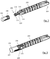
- the internal housing 158 is provided with a plurality of guide lugs (not illustrated) and pawl means 184 (cf. Fig. 1 ).
- the pawl means 184 may be an integrated part of the internal housing 158 or may be a separate component.
- a piston rod 160 extending through the main housing 154 has a first set of indentations 161' extending longitudinally along external surfaces of the piston rod 160.
- the piston rod 160 is designed and arranged to be secured against rotational movement with respect to the main housing 154.
- a second set of indentations 161 extends longitudinally along internal surfaces of the piston rod 160.
- the first set of indentations 161' of the piston rod 160 extends through and is engaged with the pawl means 184 provided on the internal housing 158 to prevent movement of the piston rod 160 in the proximal direction with respect to the housing during setting of the dose.
- a bearing surface 162 located at the distal end of the piston rod 160 is disposed to abut a proximal face of the piston 155.
- the longitudinal spacing of the first set of indentations and the second set of indentations 161 is essentially equal.
- Pawl arms 166 located on the carrier 164 are releasably engaged with the second set of indentations 161 of the piston rod 160.
- the pawl arms 166 of the carrier 164 are designed to transmit force to the piston rod 160 in the distal direction during dispense and to allow relative movement between the pinion gear 163 and the piston rod 160 in the proximal direction during setting the dose.
- the teeth of the pinion 165 may be permanently engaged with teeth of a second rack (not illustrated) of the internal housing 158.
- a drive member 167 extends about the piston rod 160 and is releasably coupled to the piston rod 160.
- the drive member 17 comprises a rack part and an activation part 169.
- the rack part and the activation part 169 are secured to each other to prevent rotational and axial movement there between.
- the drive member 167 may be a unitary component consisting of an integrated rack part and activation part 169.
- the rack part is provided with a first rack extending along the main axis of the rack part.
- the teeth of the first rack of the rack part are permanently engaged with the teeth of the pinion 165.
- the drive member 167 has a plurality of guide slots (not shown) in which the guide lugs of the internal housing 158 are located. These guide slots define the extent of permissible axial movement of the drive member 167 with respect to the housing 154. In the illustrated embodiment the guide slots also prevent rotational movement of the drive member 167 relative to the main housing 154.
- the drug delivery device 151 further comprises a resilient member 171.
- the resilient member 171 is arranged to move the drive member 167, preferably to move the drive member 167 and the piston rod 160 together, in the proximal direction with respect to the main housing 154 after dose delivery, thereby reducing or even removing pressure of the piston rod 160 on the piston 155.
- the resilient member 171 is arranged to mechanically interact with the drive member 167 at a distal end side of the drive member 167.
- the resilient member 171 is formed integrally with the internal housing 158.
- the resilient member 171 may be formed integrally with the main housing 154.
- the resilient member may be an element separate from the housing and from the internal housing.
- the resilient member 171 is a spring, for instance a circular spring, a leaf spring or a coil spring.
- the activation part 169 of the drive member 167 has a plurality of grip surfaces 172 and a dispensing face 174.
- the main housing 154 may optionally be provided with a window to the drive member through which graphical status indicators provided on the drive member 167 can be viewed.
- a user grips the grip surfaces 172 of the drive member 167.
- the user then pulls the drive member 167 in a proximal direction away from the main housing 154 thereby moving the rack part in a proximal direction.
- the proximal movement of the rack part causes the pinion 165 to rotate and move proximally by virtue of the engagement of the teeth of the pinion 165 of the pinion gear 163 with the teeth of the first rack of the rack part and the teeth of the second rack of the internal housing 158 thus moving the pinion gear 163 in the proximal direction.
- the piston rod 160 is prevented from moving proximally by interaction of pawl means 184 of the internal housing 158 with the first set of indentations 161' on the piston rod 160 during dose setting.
- the drive member 167 travels in the proximal direction relative to the piston rod 160, the pawl arms 166 of the carrier 164 are elastically displaced inwardly by interaction with the second set of indentations 161 of the piston rod 160.
- the proximal travel of the drive member 167 is limited by the guide slots of the rack part.
- the pawl arms 166 of the carrier 164 engage with the next sequential indentation of the second set of indentations 161 of the piston rod 160 as indicated in Figure 2 .
- the action of the pawl arms 166 of the carrier 164 positively engaging the second set of indentations 161 of the piston rod 160 creates an audible and tactile feedback to the user to indicate that the dose has been set.
- the user may then dispense this dose by depressing the dispensing face 174 of the activation part 169 of the drive member 167.
- the drive member 167 and the rack part are moved axially in the distal direction relative to the main housing 154.
- the pinion 165 of the pinion gear 163 is caused to rotate and move in the distal direction thus moving the pinion gear 163 longitudinally in the distal direction.
- the pawl arms 166 of the carrier 164 of the pinion gear 163 are engaged with the second set of indentations 161 of the piston rod 160, the piston rod 160 is caused to move longitudinally in the distal direction with respect to the internal housing 158.
- the distal axial movement of the piston rod 160 causes the bearing surface 162 of the piston rod 160 to bear against the piston 155 in the cartridge 153 causing the piston 155 to be deformed and moved distally, thereby causing a dose of medicament to be dispensed through the attached needle (not explicitly shown).
- the distal travel of the drive member 167 is limited by the guide slots (not explicitly shown) of the rack part.
- Audible and tactile feedback to indicate that the dose has been dispensed is provided by the interaction of the pawl means 184 of the internal housing 158 with the first set of indentations 161' of the piston rod 160.
- visual feedback regarding dose dispense may optionally be indicated by a graphical status indicator, provided on the drive member 167, which can be viewed through the optional window to the drive member in the main housing 154.
- a proximal face 176 of the carrier 164 abuts an internal distal face 178 of the piston rod 160 to prevent further axial movement of the pinion gear 163 and thus the drive member 167 in proximal direction.
- Further doses may be delivered as required up to a pre-determined maximum number of doses.
- the resilient member 171 has been biased. For example, a distal end face of the drive member may have moved into abutment with the resilient member 171 and the drive member 167 may have been moved further into the distal direction together with the resilient member 171, thereby biasing the resilient member 171.
- the biased resilient member 171 moves the drive member 167 and the piston rod 160 in the proximal direction with respect to the main housing 154.
- pressure of the piston rod 160 on the piston 155 is reduced as the piston rod is retracted from the piston. In this way, room for relaxation of the piston in the proximal direction may be provided. Relaxation of the piston 155 in the distal direction may be reduced or avoided in this way.
- unintentional weeping of the device may be reduced.
- the piston rod 160 is moved away from the piston 155 by a distance and/or the drive member 167 is moved by a distance in the range of (about) 0.1 to 2.0mm, in particular in the range of (about) 0.1 to 0.5mm, in the proximal direction with respect to the main housing 154 by means of the resilient member 171 moving the drive member 167 in the proximal direction after dose delivery.
- the distance the drive member 167 is moved does not have to be the same as the distance the piston rod 160 is moved, i.e. the piston rod 160 and the drive member 167 may be coupled with mechanical advantage.
- the piston rod 200 as illustrated in Figure 2 slightly differs from the piston rod 160 as illustrated in Figure 1 .
- the length adjusting feature of the piston rod assembly is exemplary illustrated.
- the piston rod 200 comprises a socket portion 210 at its distal end section.
- the socket portion 210 is designed as a centrally located and distally extending stud having a threaded head 212 at its free end pointing towards the distal direction.
- the distally located head 212 comprises an outer thread 214.
- the piston rod 200 is operably engaged with the drive mechanism as exemplary illustrated in connection with Figure 1 .
- the adjusting member 202 is designed as a cupped receptacle. It is of substantially hollow cylindrical shape and comprises a receptacle having an opening facing towards the proximal direction. Hence, the adjusting member 202 is adapted to threadedly receive the head 212 of the piston rod's socket portion 210.
- the receptacle 203 of the adjusting member 202 comprises an inner thread 205 corresponding and matching with the outer thread 214 of the head 212 of the socket portion 210 of the piston rod 200.
- the adjusting member 202 At its distal end face directed towards a piston of the cartridge, the adjusting member 202 comprises a contact surface 207, which is substantially planar. By way of the contact surface 207, the adjusting member may but against a proximal end face of the piston 155, preferably across its entire cross section or surface 207.
- the overall axial length of the piston rod assembly can be continuously modified in order to reduce or even to annihilate inevitable production and/or assembly tolerances of the drug delivery device 151.
- the piston rod 200 further comprises axially extending tongue members 216 comprising radially inwardly protruding lug portions 224 at least at their distal end section. Since the tongue members 216 are arranged laterally offset from the centrally located socket portion 210, a circumferential gap is formed between said tongue members 216 and the socket portion 210. The size of this circumferential gap is sufficient to receive the cylindrical side wall of the adjusting member 202.
- the adjusting member 202 comprises a corrugated outer surface 208 at its proximal end section.
- the corrugations or elongated ribs extend in longitudinal or axial direction.
- the corrugations may comprise ridge sections 218 and bottom sections 220 regularly and periodically arranged along the outer circumference of the side wall of the adjusting member 202. Between elevated ridge sections 218 and recessed bottom sections 220, here, a substantially straight flank or side section 222 extends.
- the lug portion 224 extending radially inwardly at the tongue members 216 typically matches with the profile of the corrugated surface 208 of the adjusting member 202. Since the tongue members 216 are resiliently biased with respect to the piston rod 200, they can be elastically bended radially outwardly and thus allow to rotate the adjusting member 202 with respect to the piston rod 200.
Claims (14)
- Ensemble de tige de piston pour un dispositif d'administration de médicament, comprenant :- une tige de piston (200) prévue pour être mise en prise fonctionnellement avec un piston (155) d'une cartouche (153) contenant un médicament,- au moins un organe d'ajustement (202) disposé de manière déplaçable au niveau de la tige de piston (200) par rapport au grand axe de la tige de piston (200), et interconnecté avec une section d'extrémité distale (206) de la tige de piston (200), et- au moins un moyen de verrouillage mutuel (216) prévu pour interagir avec l'organe d'ajustement (202) et/ou avec la tige de piston (200) pour verrouiller mutuellement en position l'organe d'ajustement (202) et la tige de piston (200) dans une position relative arbitraire, l'organe d'ajustement (202) et la tige de piston (200) étant en prise filetée afin de déplacer axialement la tige de piston (200) et l'organe d'ajustement (202) l'un par rapport à l'autre par rapport au grand axe de la tige de piston, et le moyen de verrouillage mutuel (216) étant prévu pour empêcher une rotation générée automatiquement de la tige de piston (200) et de l'organe d'ajustement (202) l'un par rapport à l'autre, caractérisé en ce que- les moyens de verrouillage mutuel (216) comprennent au moins un organe de type langue sollicité élastiquement (216) prévu pour venir en prise avec une portion de surface ondulée (208) de l'organe d'ajustement (202) ou de la tige de piston, l'organe d'ajustement (202) comprenant un réceptacle fileté (203) prévu pour recevoir une portion de douille distale filetée correspondante (210) de la tige de piston (200), ou
la tige de piston comprenant un réceptacle fileté prévu pour recevoir une portion de douille proximale filetée correspondante de l'organe d'ajustement, et- les moyens de verrouillage mutuel (216) venant en prise par engagement positif avec une paroi latérale du réceptacle (203). - Ensemble de tige de piston selon la revendication 1, dans lequel la portion de surface ondulée comprend des ondulations ou des nervures allongées s'étendant dans la direction longitudinale ou axiale.
- Ensemble de tige de piston selon l'une quelconque des revendications précédentes, dans lequel le moyen de verrouillage mutuel (216) est disposé sur la partie ou le composant de l'ensemble de tige de piston qui comprend la portion de douille (210).
- Ensemble de tige de piston selon l'une quelconque des revendications précédentes, dans lequel l'organe de type langue (216) est disposé de manière décalée latéralement par rapport à la portion de douille (210).
- Ensemble de tige de piston selon l'une quelconque des revendications précédentes, dans lequel une section de paroi latérale orientée radialement vers l'intérieur (205) du réceptacle (203) est filetée et dans lequel une section de paroi latérale orientée vers l'extérieur (208) du réceptacle est ondulée ou vice versa.
- Ensemble de tige de piston selon l'une quelconque des revendications précédentes, dans lequel des sections de paroi latérale filetées et ondulées (205, 214) du réceptacle (203) sont disposées de manière au moins en partie décalée dans la direction axiale.
- Ensemble de tige de piston selon l'une quelconque des revendications précédentes, dans lequel la tige de piston (200) comprend deux organes de type langue (216) déplacés axialement par rapport à la section d'extrémité distale de la tige de piston (206), et dans lequel les organes de type langue (216) comprennent des portions d'oreilles orientées radialement vers l'intérieur (224) prévues pour venir en prise avec la section de paroi latérale extérieure ondulée (208) d'une section d'extrémité proximale de l'organe d'ajustement (202).
- Ensemble de tige de piston selon l'une quelconque des revendications précédentes, dans lequel l'organe d'ajustement (202) comprend une surface de contact (207) au niveau de sa section d'extrémité distale tournée vers une section d'extrémité proximale du piston (155) dans une configuration d'assemblage.
- Dispositif d'administration de médicament pour distribuer une dose d'un médicament, comprenant :- un premier composant de boîtier (152) pour une cartouche (153) comprenant un médicament, la cartouche (153) comprenant un piston (155) disposé à l'intérieur de celle-ci de manière à pouvoir coulisser dans une direction axiale,- un deuxième composant de boîtier (154) prévu pour recevoir un mécanisme d'entraînement comprenant un ensemble de tige de piston selon l'une quelconque des revendications précédentes,- le premier et le deuxième composant de boîtier (152, 154) étant prévus pour être verrouillés mutuellement par le biais de moyens d'attache mutuellement correspondants, et l'ensemble de tige de piston étant prévu pour modifier un espace axial entre l'ensemble de tige de piston et le piston (155) à une dimension d'espace prédéfinie, la dimension de l'espace axial entre l'ensemble de tige de piston et le piston (155) pouvant être modifiée par le biais d'un engagement fileté de l'organe d'ajustement (202) et de la tige de piston (200) afin de déplacer axialement la tige de piston (200) et l'organe d'ajustement (202) l'un par rapport à l'autre dans la direction axiale, et- un moyen de verrouillage mutuel (216) étant prévu pour empêcher une rotation générée automatiquement de la tige de piston (200) et de l'organe d'ajustement (202) l'un par rapport à l'autre.
- Dispositif d'administration de médicament selon la revendication 9, dans lequel la dimension de l'espace axial entre l'ensemble de tige de piston et le piston (155) peut être modifiée en faisant tourner l'organe d'ajustement (202) et la tige de piston (200) l'un par rapport à l'autre au cours de l'assemblage du dispositif d'administration de médicament.
- Dispositif d'administration de médicament selon l'une quelconque des revendications précédentes 9 et 10, comprenant en outre un organe d'entraînement (167) accouplé de manière amovible à la tige de piston (200) et présentant en outre un organe élastique (171) qui est prévu pour déplacer l'organe d'entraînement (167) dans la direction proximale par rapport au deuxième composant de boîtier (154, 158) après l'administration de dose, de telle sorte que la tige de piston (200) soit déplacée à l'écart du piston d'une distance prédéfinie depuis une position d'utilisation jusqu'à une position de repos.
- Procédé d'assemblage d'un dispositif d'administration de médicament selon l'une quelconque des revendications précédentes 9 à 11, comprenant les étapes suivantes :- positionnement de la cartouche (153) remplie avec le médicament dans le premier composant de boîtier (152) pour former un sous-ensemble de cartouche,- positionnement du mécanisme d'entraînement comprenant l'ensemble de tige de piston selon l'une quelconque des revendications précédentes 1 à 8 dans le deuxième composant de boîtier (154) pour former un sous-ensemble de boîtier,- détermination de la position axiale du piston (155) par rapport au premier composant de boîtier (152),- détermination de la position axiale de l'ensemble de tige de piston par rapport au deuxième composant de boîtier (154),- modification des dimensions axiales de l'ensemble de tige de piston en déplaçant l'organe d'ajustement (202) par rapport à la tige de piston (200) de telle sorte que la distance axiale entre le piston (155) et l'ensemble de tige de piston soit égale à la dimension d'espace prédéfinie lorsque le dispositif d'administration de médicament est finalement assemblé,- interconnexion mutuelle du premier et du deuxième composant de boîtier (152, 154).
- Procédé selon la revendication 12, dans lequel la position axiale de l'ensemble de tige de piston est mesurée par rapport à au moins un point de référence du deuxième composant de boîtier (154) lorsque la tige de piston (200) est dans sa position d'utilisation.
- Procédé selon la revendication 12 ou 13, dans lequel les dimensions axiales de l'ensemble de tige de piston sont modifiées lorsque la tige de piston (200) est dans sa position d'utilisation.
Priority Applications (2)
| Application Number | Priority Date | Filing Date | Title |
|---|---|---|---|
| EP11711562.6A EP2552519B1 (fr) | 2010-03-31 | 2011-03-31 | Ensemble tige de piston pour dispositif d'administration de médicament |
| EP19219202.9A EP3662947A1 (fr) | 2010-03-31 | 2011-03-31 | Ensemble tige de piston pour dispositif d'administration de médicaments |
Applications Claiming Priority (4)
| Application Number | Priority Date | Filing Date | Title |
|---|---|---|---|
| EP10158613 | 2010-03-31 | ||
| US12/791,499 US8986259B2 (en) | 2010-03-31 | 2010-06-01 | Piston rod assembly for a drug delivery device |
| PCT/EP2011/054986 WO2011121061A1 (fr) | 2010-03-31 | 2011-03-31 | Ensemble tige de piston pour dispositif d'administration de médicament |
| EP11711562.6A EP2552519B1 (fr) | 2010-03-31 | 2011-03-31 | Ensemble tige de piston pour dispositif d'administration de médicament |
Related Child Applications (2)
| Application Number | Title | Priority Date | Filing Date |
|---|---|---|---|
| EP19219202.9A Division EP3662947A1 (fr) | 2010-03-31 | 2011-03-31 | Ensemble tige de piston pour dispositif d'administration de médicaments |
| EP19219202.9A Division-Into EP3662947A1 (fr) | 2010-03-31 | 2011-03-31 | Ensemble tige de piston pour dispositif d'administration de médicaments |
Publications (2)
| Publication Number | Publication Date |
|---|---|
| EP2552519A1 EP2552519A1 (fr) | 2013-02-06 |
| EP2552519B1 true EP2552519B1 (fr) | 2020-04-22 |
Family
ID=42670391
Family Applications (2)
| Application Number | Title | Priority Date | Filing Date |
|---|---|---|---|
| EP11711562.6A Active EP2552519B1 (fr) | 2010-03-31 | 2011-03-31 | Ensemble tige de piston pour dispositif d'administration de médicament |
| EP19219202.9A Pending EP3662947A1 (fr) | 2010-03-31 | 2011-03-31 | Ensemble tige de piston pour dispositif d'administration de médicaments |
Family Applications After (1)
| Application Number | Title | Priority Date | Filing Date |
|---|---|---|---|
| EP19219202.9A Pending EP3662947A1 (fr) | 2010-03-31 | 2011-03-31 | Ensemble tige de piston pour dispositif d'administration de médicaments |
Country Status (15)
| Country | Link |
|---|---|
| US (2) | US8986259B2 (fr) |
| EP (2) | EP2552519B1 (fr) |
| JP (1) | JP5797257B2 (fr) |
| KR (1) | KR20130041793A (fr) |
| CN (1) | CN102917743B (fr) |
| AU (1) | AU2011234479A1 (fr) |
| BR (1) | BR112012024546A2 (fr) |
| CA (1) | CA2794985A1 (fr) |
| DK (1) | DK2552519T3 (fr) |
| MX (1) | MX2012010284A (fr) |
| NZ (1) | NZ602539A (fr) |
| RU (1) | RU2012146376A (fr) |
| SG (1) | SG184328A1 (fr) |
| WO (1) | WO2011121061A1 (fr) |
| ZA (1) | ZA201206321B (fr) |
Families Citing this family (53)
| Publication number | Priority date | Publication date | Assignee | Title |
|---|---|---|---|---|
| ES2314182T3 (es) | 2002-02-11 | 2009-03-16 | Antares Pharma, Inc. | Inyector intradermico. |
| EP1850892B2 (fr) | 2005-01-24 | 2023-04-19 | Antares Pharma, Inc. | Injecteur a seringue preremplie assiste d'une aiguille |
| WO2007131013A1 (fr) | 2006-05-03 | 2007-11-15 | Antares Pharma, Inc. | Injecteur de reconstitution à deux étages |
| US9144648B2 (en) | 2006-05-03 | 2015-09-29 | Antares Pharma, Inc. | Injector with adjustable dosing |
| EP2077132A1 (fr) | 2008-01-02 | 2009-07-08 | Boehringer Ingelheim Pharma GmbH & Co. KG | Dispositif distributeur, dispositif de stockage et procédé pour la distribution d'une formulation |
| WO2009114542A1 (fr) | 2008-03-10 | 2009-09-17 | Antares Pharma, Inc. | Dispositif de sécurité pour injecteur |
| EP2318075B1 (fr) | 2008-08-05 | 2019-05-22 | Antares Pharma, Inc. | Injecteur à dosage multiple |
| EP2408493A1 (fr) | 2009-03-20 | 2012-01-25 | Antares Pharma, Inc. | Système d'injection d'agents dangereux |
| US10011906B2 (en) | 2009-03-31 | 2018-07-03 | Beohringer Ingelheim International Gmbh | Method for coating a surface of a component |
| EP3508239B1 (fr) | 2009-05-18 | 2020-12-23 | Boehringer Ingelheim International GmbH | Adaptateur, dispositif d'inhalation et pulvérisateur |
| WO2011064163A1 (fr) | 2009-11-25 | 2011-06-03 | Boehringer Ingelheim International Gmbh | Nébuliseur |
| US10016568B2 (en) | 2009-11-25 | 2018-07-10 | Boehringer Ingelheim International Gmbh | Nebulizer |
| US8986259B2 (en) * | 2010-03-31 | 2015-03-24 | Sanofi-Aventis Deutschland Gmbh | Piston rod assembly for a drug delivery device |
| EP2585151B1 (fr) | 2010-06-24 | 2018-04-04 | Boehringer Ingelheim International GmbH | Nébuliseur |
| US9827384B2 (en) | 2011-05-23 | 2017-11-28 | Boehringer Ingelheim International Gmbh | Nebulizer |
| CA2840943A1 (fr) * | 2011-07-14 | 2013-01-17 | Sanofi-Aventis Deutschland Gmbh | Mecanisme d'entrainement d'un dispositif d'administration de medicament |
| US8496619B2 (en) | 2011-07-15 | 2013-07-30 | Antares Pharma, Inc. | Injection device with cammed ram assembly |
| US9220660B2 (en) | 2011-07-15 | 2015-12-29 | Antares Pharma, Inc. | Liquid-transfer adapter beveled spike |
| AR088084A1 (es) | 2011-09-29 | 2014-05-07 | Sanofi Aventis Deutschland | Aparato para administracion de medicamentos y procedimiento de montaje de un aparato para administracion de medicamentos |
| IL217272A0 (en) * | 2011-12-29 | 2012-02-29 | Omrix Biopharmaceuticals | System for delivery of fluids and use thereof |
| PT2822618T (pt) | 2012-03-06 | 2024-03-04 | Antares Pharma Inc | Seringa pré-cheia com característica de força de rutura |
| JP6457383B2 (ja) | 2012-04-06 | 2019-01-23 | アンタレス・ファーマ・インコーポレーテッド | テストステロン組成物の針支援式ジェット注入投与 |
| WO2013152894A1 (fr) | 2012-04-13 | 2013-10-17 | Boehringer Ingelheim International Gmbh | Pulvérisateur comprenant des moyens de détrompage |
| WO2013169804A1 (fr) | 2012-05-07 | 2013-11-14 | Antares Pharma, Inc. | Dispositif d'injection par jet assisté par une aiguille, présentant une force de déclenchement réduite |
| EP2885033A1 (fr) * | 2012-08-20 | 2015-06-24 | Sanofi-Aventis Deutschland GmbH | Dispositif d'administration de médicament et procédé de détection de contact entre une tige de piston et une bonde de cartouche par excitation de vibration et surveillance |
| DK2885032T3 (en) * | 2012-08-20 | 2018-05-22 | Sanofi Aventis Deutschland | PHARMACEUTICAL APPLICATION DEVICE AND METHOD FOR DETECTING CONTACT BETWEEN PISTON PISTON AND PATTERN PROTECTOR AT DISTANCE MEASUREMENT |
| WO2014029682A2 (fr) * | 2012-08-20 | 2014-02-27 | Sanofi-Aventis Deutschland Gmbh | Procédé d'assemblage d'un dispositif d'administration de médicament |
| CN104640587B (zh) * | 2012-09-11 | 2017-11-21 | 赛诺菲-安万特德国有限公司 | 用于药物输送装置的驱动机构和药物输送装置 |
| TWI599377B (zh) | 2013-01-15 | 2017-09-21 | 卡貝歐洲有限公司 | 藥物輸送裝置 |
| ES2763633T3 (es) | 2013-02-11 | 2020-05-29 | Antares Pharma Inc | Dispositivo de inyección por chorro asistido por aguja que tiene fuerza de disparo reducida |
| ES2742046T3 (es) | 2013-03-11 | 2020-02-12 | Antares Pharma Inc | Inyector de dosis con sistema de piñón |
| WO2014165136A1 (fr) | 2013-03-12 | 2014-10-09 | Antares Pharma, Inc. | Seringues pré-remplies à volume constant et leurs trousses |
| EP2983763B1 (fr) * | 2013-04-10 | 2017-05-24 | Sanofi | Mécanisme dýentraînement pour dispositif d'administration de médicaments |
| ES2836977T3 (es) | 2013-08-09 | 2021-06-28 | Boehringer Ingelheim Int | Nebulizador |
| WO2015018904A1 (fr) * | 2013-08-09 | 2015-02-12 | Boehringer Ingelheim International Gmbh | Nébuliseur |
| KR20160046841A (ko) * | 2013-08-22 | 2016-04-29 | 사노피-아벤티스 도이칠란트 게엠베하 | 약물 전달 장치용 구동 기구, 및 약물 전달 장치의 조립 방법 |
| EP3041545A1 (fr) * | 2013-09-03 | 2016-07-13 | Sanofi | Ensemble d'entraînement pour dispositif d'administration de médicament |
| WO2015074981A2 (fr) * | 2013-11-22 | 2015-05-28 | Sanofi-Aventis Deutschland Gmbh | Dispositif d'administration de médicament |
| JP6748655B2 (ja) | 2014-12-08 | 2020-09-02 | サノフイSanofi | 薬物送達デバイスを組み立てる方法および薬物送達デバイス |
| DE102015000999A1 (de) * | 2015-01-27 | 2016-07-28 | Sarl Omsi | Kolben für Spritzen und Spritzen |
| US10441722B2 (en) * | 2015-04-29 | 2019-10-15 | Novo Nordisk A/S | Drug delivery device with spring mechanism |
| GB2541445B (en) * | 2015-08-20 | 2018-04-18 | Owen Mumford Ltd | Injection device |
| CN107787237B (zh) * | 2015-07-01 | 2021-02-02 | 诺和诺德股份有限公司 | 药物输送装置 |
| CN108025145B (zh) * | 2015-10-01 | 2020-08-25 | 诺和诺德股份有限公司 | 活塞垫圈组件、组装的方法和药物输送装置 |
| US10661019B2 (en) | 2015-11-27 | 2020-05-26 | Shl Medical Ag | Medicament delivery device |
| KR102257732B1 (ko) | 2016-05-06 | 2021-05-31 | 에스에이치엘 메디컬 아게 | 약물 전달 장치용 구동 조립체 |
| US20210283340A1 (en) * | 2016-07-08 | 2021-09-16 | Novo Nordisk A/S | Drug delivery device comprising an adjustment member |
| EP3562532B1 (fr) | 2016-12-31 | 2021-10-06 | Novo Nordisk A/S | Sous-ensemble piston pour un injecteur de médicament pré-rempli, injecteur de médicament pré-rempli et procédé d'assemblage d'un injecteur médical pré-rempli |
| JP7111809B2 (ja) * | 2017-10-16 | 2022-08-02 | ベクトン・ディキンソン・アンド・カンパニー | 薬物送達デバイス用のスペーサアセンブリ |
| EP3622987A1 (fr) * | 2018-09-11 | 2020-03-18 | Tecpharma Licensing AG | Procédé d'assemblage d'un dispositif d'injection ou de perfusion |
| GB2577538B (en) * | 2018-09-28 | 2021-10-13 | Owen Mumford Ltd | Injection device fill volume management |
| GB2584730B (en) * | 2019-06-14 | 2022-04-13 | Owen Mumford Ltd | Drug delivery device assembly |
| EP4196195A1 (fr) * | 2020-08-12 | 2023-06-21 | Sanofi | Dispositif d'injection et mécanisme de limitation de dose |
Citations (1)
| Publication number | Priority date | Publication date | Assignee | Title |
|---|---|---|---|---|
| US6350094B1 (en) * | 1998-12-04 | 2002-02-26 | Hitachi, Ltd. | Bolt and a nut locking mechanism |
Family Cites Families (28)
| Publication number | Priority date | Publication date | Assignee | Title |
|---|---|---|---|---|
| US2681297A (en) | 1950-10-31 | 1954-06-15 | Mattox And Moore Inc | Veterinary estrogen composition and administration method |
| US2895474A (en) * | 1955-01-04 | 1959-07-21 | Cook Waite Lab Inc | Aspirating cartridge syringe |
| US3224445A (en) * | 1956-03-01 | 1965-12-21 | Cook Waite Lab Inc | Aspirating syringe |
| US3115135A (en) * | 1962-03-12 | 1963-12-24 | Stanley J Sarnoff | Aspirating piston and plunger coupling |
| US4064879A (en) * | 1976-04-06 | 1977-12-27 | Metatech Corporation | Pressure-indicating syringe |
| US4333458A (en) * | 1981-02-09 | 1982-06-08 | Sterling Drug Inc. | Self-aspirating syringe with positively engaged locking collet |
| US4492576A (en) * | 1982-06-15 | 1985-01-08 | Dragan William B | Dental syringe and method of packaging and dispensing a dental material |
| DE8813905U1 (fr) * | 1988-11-07 | 1989-12-07 | Nothdurft, Klaus, 7000 Stuttgart, De | |
| US5226895A (en) * | 1989-06-05 | 1993-07-13 | Eli Lilly And Company | Multiple dose injection pen |
| GB9226423D0 (en) * | 1992-12-18 | 1993-02-10 | Sams Bernard | Incrementing mechanisms |
| CA2131036A1 (fr) * | 1993-09-29 | 1995-03-30 | William A. Bergstresser | Piston pour seringue a cartouche utilisant une cartouche a aiguille integree |
| US5957896A (en) * | 1997-08-11 | 1999-09-28 | Becton, Dickinson And Company | Medication delivery pen |
| EP1487520A1 (fr) * | 2002-03-18 | 2004-12-22 | Eli Lilly And Company | Appareil de distribution de medicament dote d'un train d'engrenages apportant un avantage technique |
| DE10237258B4 (de) * | 2002-08-14 | 2006-09-21 | Tecpharma Licensing Ag | Injektionsvorrichtung |
| GB0304823D0 (en) * | 2003-03-03 | 2003-04-09 | Dca Internat Ltd | Improvements in and relating to a pen-type injector |
| DE10351596B4 (de) * | 2003-11-05 | 2007-10-11 | Tecpharma Licensing Ag | Autoinjektor mit variabler Dosis |
| NZ554828A (en) * | 2004-12-06 | 2010-07-30 | Washington Biotech Corp | Medicine injection devices and methods |
| US20060129122A1 (en) * | 2004-12-06 | 2006-06-15 | Wyrick Ronald E | Method and apparatus for delivering epinephrine |
| EP1923083A1 (fr) * | 2006-11-17 | 2008-05-21 | Sanofi-Aventis Deutschland GmbH | Mécanismes d'entraînement destinés à être utilisés dans des dispositifs d'administration de médicaments |
| BRPI0907110A2 (pt) * | 2008-01-28 | 2019-09-24 | Novo Nordisk As | dispositivo de injeção para realizar injeções médicas |
| WO2010029043A1 (fr) * | 2008-09-09 | 2010-03-18 | Shl Group Ab | Dispositif d'administration de médicament |
| US8475414B2 (en) * | 2008-12-02 | 2013-07-02 | Sanofi-Aventis Deutschland Gmbh | Medication delivery device and method for operating a medication delivery device |
| US9089652B2 (en) * | 2008-12-12 | 2015-07-28 | Sanofi-Aventis Deutschland Gmbh | Drive mechanism for a medication delivery device and medication delivery device |
| CA2757136A1 (fr) * | 2009-03-31 | 2010-10-07 | Sanofi-Aventis Deutschland Gmbh | Ameliorations concernant des dispositifs d'administration de medicament |
| WO2011039233A1 (fr) * | 2009-09-30 | 2011-04-07 | Sanofi-Aventis Deutschland Gmbh | Dispositif d'injection |
| CA2773672A1 (fr) * | 2009-09-30 | 2011-04-07 | Sanofi-Aventis Deutschland Gmbh | Ensemble d'entrainement a remise a zero et dispositif d'administration de medicament |
| US8986259B2 (en) * | 2010-03-31 | 2015-03-24 | Sanofi-Aventis Deutschland Gmbh | Piston rod assembly for a drug delivery device |
| AR088084A1 (es) * | 2011-09-29 | 2014-05-07 | Sanofi Aventis Deutschland | Aparato para administracion de medicamentos y procedimiento de montaje de un aparato para administracion de medicamentos |
-
2010
- 2010-06-01 US US12/791,499 patent/US8986259B2/en active Active
-
2011
- 2011-03-31 RU RU2012146376/14A patent/RU2012146376A/ru not_active Application Discontinuation
- 2011-03-31 CA CA2794985A patent/CA2794985A1/fr not_active Abandoned
- 2011-03-31 US US13/582,568 patent/US9084852B2/en active Active
- 2011-03-31 BR BR112012024546A patent/BR112012024546A2/pt not_active IP Right Cessation
- 2011-03-31 WO PCT/EP2011/054986 patent/WO2011121061A1/fr active Application Filing
- 2011-03-31 SG SG2012072179A patent/SG184328A1/en unknown
- 2011-03-31 JP JP2013501846A patent/JP5797257B2/ja active Active
- 2011-03-31 AU AU2011234479A patent/AU2011234479A1/en not_active Abandoned
- 2011-03-31 KR KR1020127028393A patent/KR20130041793A/ko not_active Application Discontinuation
- 2011-03-31 CN CN201180027006.2A patent/CN102917743B/zh not_active Expired - Fee Related
- 2011-03-31 EP EP11711562.6A patent/EP2552519B1/fr active Active
- 2011-03-31 NZ NZ602539A patent/NZ602539A/xx not_active IP Right Cessation
- 2011-03-31 EP EP19219202.9A patent/EP3662947A1/fr active Pending
- 2011-03-31 DK DK11711562.6T patent/DK2552519T3/da active
- 2011-03-31 MX MX2012010284A patent/MX2012010284A/es not_active Application Discontinuation
-
2012
- 2012-08-22 ZA ZA2012/06321A patent/ZA201206321B/en unknown
Patent Citations (1)
| Publication number | Priority date | Publication date | Assignee | Title |
|---|---|---|---|---|
| US6350094B1 (en) * | 1998-12-04 | 2002-02-26 | Hitachi, Ltd. | Bolt and a nut locking mechanism |
Also Published As
| Publication number | Publication date |
|---|---|
| DK2552519T3 (da) | 2020-07-20 |
| EP3662947A1 (fr) | 2020-06-10 |
| RU2012146376A (ru) | 2014-05-10 |
| US8986259B2 (en) | 2015-03-24 |
| CN102917743B (zh) | 2015-06-24 |
| ZA201206321B (en) | 2013-03-27 |
| US20130066279A1 (en) | 2013-03-14 |
| SG184328A1 (en) | 2012-11-29 |
| MX2012010284A (es) | 2012-09-28 |
| NZ602539A (en) | 2013-08-30 |
| WO2011121061A1 (fr) | 2011-10-06 |
| BR112012024546A2 (pt) | 2017-08-08 |
| CN102917743A (zh) | 2013-02-06 |
| JP5797257B2 (ja) | 2015-10-21 |
| US20110245780A1 (en) | 2011-10-06 |
| KR20130041793A (ko) | 2013-04-25 |
| CA2794985A1 (fr) | 2011-10-06 |
| US9084852B2 (en) | 2015-07-21 |
| JP2013523235A (ja) | 2013-06-17 |
| AU2011234479A1 (en) | 2012-10-18 |
| EP2552519A1 (fr) | 2013-02-06 |
Similar Documents
| Publication | Publication Date | Title |
|---|---|---|
| EP2552519B1 (fr) | Ensemble tige de piston pour dispositif d'administration de médicament | |
| EP2509662B1 (fr) | Ensemble entraînement pour dispositif d'administration de médicament et dispositif d'administration de médicament | |
| EP2509663B1 (fr) | Ensemble de commande pour dispositif d'administration de médicaments et dispositif d'administration de médicaments | |
| EP2512562B1 (fr) | Un dispositif d'administration de médicaments | |
| AU2010302982B2 (en) | Drive mechanism for a drug delivery device | |
| EP2624892B1 (fr) | Mécanisme d'entraînement pour un dispositif d'administration de médicament et dispositif d'administration de médicament | |
| EP2485791A1 (fr) | Mécanisme d'entraînement pour dispositifs de délivrance de médicament | |
| EP2571553B1 (fr) | Ensemble formant une aiguille pour dispositifs d'administration de médicaments | |
| EP2455122A1 (fr) | Mécanisme d'entraînement pour dispositif d'approvisionnement de médicament | |
| EP2731650B1 (fr) | Mécanisme d'entraînement d'un dispositif d'administration de médicament | |
| CA2811953C (fr) | Mecanisme d'entrainement pour un dispositif d'administration de medicament et dispositif d'administration de medicament |
Legal Events
| Date | Code | Title | Description |
|---|---|---|---|
| PUAI | Public reference made under article 153(3) epc to a published international application that has entered the european phase |
Free format text: ORIGINAL CODE: 0009012 |
|
| 17P | Request for examination filed |
Effective date: 20121031 |
|
| AK | Designated contracting states |
Kind code of ref document: A1 Designated state(s): AL AT BE BG CH CY CZ DE DK EE ES FI FR GB GR HR HU IE IS IT LI LT LU LV MC MK MT NL NO PL PT RO RS SE SI SK SM TR |
|
| AX | Request for extension of the european patent |
Extension state: BA ME |
|
| REG | Reference to a national code |
Ref country code: HK Ref legal event code: DE Ref document number: 1181336 Country of ref document: HK |
|
| STAA | Information on the status of an ep patent application or granted ep patent |
Free format text: STATUS: EXAMINATION IS IN PROGRESS |
|
| 17Q | First examination report despatched |
Effective date: 20171025 |
|
| GRAP | Despatch of communication of intention to grant a patent |
Free format text: ORIGINAL CODE: EPIDOSNIGR1 |
|
| STAA | Information on the status of an ep patent application or granted ep patent |
Free format text: STATUS: GRANT OF PATENT IS INTENDED |
|
| INTG | Intention to grant announced |
Effective date: 20190822 |
|
| REG | Reference to a national code |
Ref country code: HK Ref legal event code: WD Ref document number: 1181336 Country of ref document: HK |
|
| GRAJ | Information related to disapproval of communication of intention to grant by the applicant or resumption of examination proceedings by the epo deleted |
Free format text: ORIGINAL CODE: EPIDOSDIGR1 |
|
| STAA | Information on the status of an ep patent application or granted ep patent |
Free format text: STATUS: EXAMINATION IS IN PROGRESS |
|
| INTC | Intention to grant announced (deleted) | ||
| GRAP | Despatch of communication of intention to grant a patent |
Free format text: ORIGINAL CODE: EPIDOSNIGR1 |
|
| STAA | Information on the status of an ep patent application or granted ep patent |
Free format text: STATUS: GRANT OF PATENT IS INTENDED |
|
| GRAS | Grant fee paid |
Free format text: ORIGINAL CODE: EPIDOSNIGR3 |
|
| INTG | Intention to grant announced |
Effective date: 20200219 |
|
| GRAA | (expected) grant |
Free format text: ORIGINAL CODE: 0009210 |
|
| STAA | Information on the status of an ep patent application or granted ep patent |
Free format text: STATUS: THE PATENT HAS BEEN GRANTED |
|
| AK | Designated contracting states |
Kind code of ref document: B1 Designated state(s): AL AT BE BG CH CY CZ DE DK EE ES FI FR GB GR HR HU IE IS IT LI LT LU LV MC MK MT NL NO PL PT RO RS SE SI SK SM TR |
|
| AX | Request for extension of the european patent |
Extension state: BA ME |
|
| REG | Reference to a national code |
Ref country code: GB Ref legal event code: FG4D |
|
| REG | Reference to a national code |
Ref country code: CH Ref legal event code: EP |
|
| REG | Reference to a national code |
Ref country code: DE Ref legal event code: R096 Ref document number: 602011066374 Country of ref document: DE |
|
| REG | Reference to a national code |
Ref country code: IE Ref legal event code: FG4D |
|
| REG | Reference to a national code |
Ref country code: AT Ref legal event code: REF Ref document number: 1259249 Country of ref document: AT Kind code of ref document: T Effective date: 20200515 |
|
| REG | Reference to a national code |
Ref country code: DK Ref legal event code: T3 Effective date: 20200715 |
|
| REG | Reference to a national code |
Ref country code: LT Ref legal event code: MG4D |
|
| REG | Reference to a national code |
Ref country code: NL Ref legal event code: MP Effective date: 20200422 |
|
| PG25 | Lapsed in a contracting state [announced via postgrant information from national office to epo] |
Ref country code: LT Free format text: LAPSE BECAUSE OF FAILURE TO SUBMIT A TRANSLATION OF THE DESCRIPTION OR TO PAY THE FEE WITHIN THE PRESCRIBED TIME-LIMIT Effective date: 20200422 Ref country code: SE Free format text: LAPSE BECAUSE OF FAILURE TO SUBMIT A TRANSLATION OF THE DESCRIPTION OR TO PAY THE FEE WITHIN THE PRESCRIBED TIME-LIMIT Effective date: 20200422 Ref country code: NL Free format text: LAPSE BECAUSE OF FAILURE TO SUBMIT A TRANSLATION OF THE DESCRIPTION OR TO PAY THE FEE WITHIN THE PRESCRIBED TIME-LIMIT Effective date: 20200422 Ref country code: PT Free format text: LAPSE BECAUSE OF FAILURE TO SUBMIT A TRANSLATION OF THE DESCRIPTION OR TO PAY THE FEE WITHIN THE PRESCRIBED TIME-LIMIT Effective date: 20200824 Ref country code: FI Free format text: LAPSE BECAUSE OF FAILURE TO SUBMIT A TRANSLATION OF THE DESCRIPTION OR TO PAY THE FEE WITHIN THE PRESCRIBED TIME-LIMIT Effective date: 20200422 Ref country code: IS Free format text: LAPSE BECAUSE OF FAILURE TO SUBMIT A TRANSLATION OF THE DESCRIPTION OR TO PAY THE FEE WITHIN THE PRESCRIBED TIME-LIMIT Effective date: 20200822 Ref country code: NO Free format text: LAPSE BECAUSE OF FAILURE TO SUBMIT A TRANSLATION OF THE DESCRIPTION OR TO PAY THE FEE WITHIN THE PRESCRIBED TIME-LIMIT Effective date: 20200722 Ref country code: GR Free format text: LAPSE BECAUSE OF FAILURE TO SUBMIT A TRANSLATION OF THE DESCRIPTION OR TO PAY THE FEE WITHIN THE PRESCRIBED TIME-LIMIT Effective date: 20200723 |
|
| REG | Reference to a national code |
Ref country code: AT Ref legal event code: MK05 Ref document number: 1259249 Country of ref document: AT Kind code of ref document: T Effective date: 20200422 |
|
| PG25 | Lapsed in a contracting state [announced via postgrant information from national office to epo] |
Ref country code: LV Free format text: LAPSE BECAUSE OF FAILURE TO SUBMIT A TRANSLATION OF THE DESCRIPTION OR TO PAY THE FEE WITHIN THE PRESCRIBED TIME-LIMIT Effective date: 20200422 Ref country code: RS Free format text: LAPSE BECAUSE OF FAILURE TO SUBMIT A TRANSLATION OF THE DESCRIPTION OR TO PAY THE FEE WITHIN THE PRESCRIBED TIME-LIMIT Effective date: 20200422 Ref country code: BG Free format text: LAPSE BECAUSE OF FAILURE TO SUBMIT A TRANSLATION OF THE DESCRIPTION OR TO PAY THE FEE WITHIN THE PRESCRIBED TIME-LIMIT Effective date: 20200722 Ref country code: HR Free format text: LAPSE BECAUSE OF FAILURE TO SUBMIT A TRANSLATION OF THE DESCRIPTION OR TO PAY THE FEE WITHIN THE PRESCRIBED TIME-LIMIT Effective date: 20200422 |
|
| PG25 | Lapsed in a contracting state [announced via postgrant information from national office to epo] |
Ref country code: AL Free format text: LAPSE BECAUSE OF FAILURE TO SUBMIT A TRANSLATION OF THE DESCRIPTION OR TO PAY THE FEE WITHIN THE PRESCRIBED TIME-LIMIT Effective date: 20200422 |
|
| REG | Reference to a national code |
Ref country code: DE Ref legal event code: R097 Ref document number: 602011066374 Country of ref document: DE |
|
| PG25 | Lapsed in a contracting state [announced via postgrant information from national office to epo] |
Ref country code: RO Free format text: LAPSE BECAUSE OF FAILURE TO SUBMIT A TRANSLATION OF THE DESCRIPTION OR TO PAY THE FEE WITHIN THE PRESCRIBED TIME-LIMIT Effective date: 20200422 Ref country code: CZ Free format text: LAPSE BECAUSE OF FAILURE TO SUBMIT A TRANSLATION OF THE DESCRIPTION OR TO PAY THE FEE WITHIN THE PRESCRIBED TIME-LIMIT Effective date: 20200422 Ref country code: SM Free format text: LAPSE BECAUSE OF FAILURE TO SUBMIT A TRANSLATION OF THE DESCRIPTION OR TO PAY THE FEE WITHIN THE PRESCRIBED TIME-LIMIT Effective date: 20200422 Ref country code: IT Free format text: LAPSE BECAUSE OF FAILURE TO SUBMIT A TRANSLATION OF THE DESCRIPTION OR TO PAY THE FEE WITHIN THE PRESCRIBED TIME-LIMIT Effective date: 20200422 Ref country code: AT Free format text: LAPSE BECAUSE OF FAILURE TO SUBMIT A TRANSLATION OF THE DESCRIPTION OR TO PAY THE FEE WITHIN THE PRESCRIBED TIME-LIMIT Effective date: 20200422 Ref country code: EE Free format text: LAPSE BECAUSE OF FAILURE TO SUBMIT A TRANSLATION OF THE DESCRIPTION OR TO PAY THE FEE WITHIN THE PRESCRIBED TIME-LIMIT Effective date: 20200422 Ref country code: ES Free format text: LAPSE BECAUSE OF FAILURE TO SUBMIT A TRANSLATION OF THE DESCRIPTION OR TO PAY THE FEE WITHIN THE PRESCRIBED TIME-LIMIT Effective date: 20200422 |
|
| PG25 | Lapsed in a contracting state [announced via postgrant information from national office to epo] |
Ref country code: SK Free format text: LAPSE BECAUSE OF FAILURE TO SUBMIT A TRANSLATION OF THE DESCRIPTION OR TO PAY THE FEE WITHIN THE PRESCRIBED TIME-LIMIT Effective date: 20200422 Ref country code: PL Free format text: LAPSE BECAUSE OF FAILURE TO SUBMIT A TRANSLATION OF THE DESCRIPTION OR TO PAY THE FEE WITHIN THE PRESCRIBED TIME-LIMIT Effective date: 20200422 |
|
| PLBE | No opposition filed within time limit |
Free format text: ORIGINAL CODE: 0009261 |
|
| STAA | Information on the status of an ep patent application or granted ep patent |
Free format text: STATUS: NO OPPOSITION FILED WITHIN TIME LIMIT |
|
| 26N | No opposition filed |
Effective date: 20210125 |
|
| PG25 | Lapsed in a contracting state [announced via postgrant information from national office to epo] |
Ref country code: SI Free format text: LAPSE BECAUSE OF FAILURE TO SUBMIT A TRANSLATION OF THE DESCRIPTION OR TO PAY THE FEE WITHIN THE PRESCRIBED TIME-LIMIT Effective date: 20200422 |
|
| PG25 | Lapsed in a contracting state [announced via postgrant information from national office to epo] |
Ref country code: MC Free format text: LAPSE BECAUSE OF FAILURE TO SUBMIT A TRANSLATION OF THE DESCRIPTION OR TO PAY THE FEE WITHIN THE PRESCRIBED TIME-LIMIT Effective date: 20200422 |
|
| REG | Reference to a national code |
Ref country code: BE Ref legal event code: MM Effective date: 20210331 |
|
| PG25 | Lapsed in a contracting state [announced via postgrant information from national office to epo] |
Ref country code: IE Free format text: LAPSE BECAUSE OF NON-PAYMENT OF DUE FEES Effective date: 20210331 Ref country code: LU Free format text: LAPSE BECAUSE OF NON-PAYMENT OF DUE FEES Effective date: 20210331 |
|
| PG25 | Lapsed in a contracting state [announced via postgrant information from national office to epo] |
Ref country code: BE Free format text: LAPSE BECAUSE OF NON-PAYMENT OF DUE FEES Effective date: 20210331 |
|
| PGFP | Annual fee paid to national office [announced via postgrant information from national office to epo] |
Ref country code: FR Payment date: 20230208 Year of fee payment: 13 Ref country code: DK Payment date: 20230314 Year of fee payment: 13 |
|
| PG25 | Lapsed in a contracting state [announced via postgrant information from national office to epo] |
Ref country code: HU Free format text: LAPSE BECAUSE OF FAILURE TO SUBMIT A TRANSLATION OF THE DESCRIPTION OR TO PAY THE FEE WITHIN THE PRESCRIBED TIME-LIMIT; INVALID AB INITIO Effective date: 20110331 Ref country code: CY Free format text: LAPSE BECAUSE OF FAILURE TO SUBMIT A TRANSLATION OF THE DESCRIPTION OR TO PAY THE FEE WITHIN THE PRESCRIBED TIME-LIMIT Effective date: 20200422 |
|
| PGFP | Annual fee paid to national office [announced via postgrant information from national office to epo] |
Ref country code: TR Payment date: 20230330 Year of fee payment: 13 Ref country code: GB Payment date: 20230209 Year of fee payment: 13 Ref country code: DE Payment date: 20230131 Year of fee payment: 13 |
|
| PGFP | Annual fee paid to national office [announced via postgrant information from national office to epo] |
Ref country code: CH Payment date: 20230401 Year of fee payment: 13 |