EP2509663B1 - Ensemble de commande pour dispositif d'administration de médicaments et dispositif d'administration de médicaments - Google Patents
Ensemble de commande pour dispositif d'administration de médicaments et dispositif d'administration de médicaments Download PDFInfo
- Publication number
- EP2509663B1 EP2509663B1 EP10800903.6A EP10800903A EP2509663B1 EP 2509663 B1 EP2509663 B1 EP 2509663B1 EP 10800903 A EP10800903 A EP 10800903A EP 2509663 B1 EP2509663 B1 EP 2509663B1
- Authority
- EP
- European Patent Office
- Prior art keywords
- drive member
- housing
- piston rod
- relative
- drive assembly
- Prior art date
- Legal status (The legal status is an assumption and is not a legal conclusion. Google has not performed a legal analysis and makes no representation as to the accuracy of the status listed.)
- Active
Links
- 238000012377 drug delivery Methods 0.000 title claims description 31
- 229940079593 drug Drugs 0.000 claims description 51
- 239000003814 drug Substances 0.000 claims description 51
- 230000007423 decrease Effects 0.000 claims description 18
- 238000006073 displacement reaction Methods 0.000 claims description 6
- 238000007906 compression Methods 0.000 claims description 4
- 230000006835 compression Effects 0.000 claims description 4
- JUFFVKRROAPVBI-PVOYSMBESA-N chembl1210015 Chemical compound C([C@@H](C(=O)N[C@@H]([C@@H](C)CC)C(=O)N[C@@H](CCC(O)=O)C(=O)N[C@@H](CC=1C2=CC=CC=C2NC=1)C(=O)N[C@@H](CC(C)C)C(=O)N[C@@H](CCCCN)C(=O)N[C@@H](CC(=O)N[C@H]1[C@@H]([C@@H](O)[C@H](O[C@H]2[C@@H]([C@@H](O)[C@@H](O)[C@@H](CO[C@]3(O[C@@H](C[C@H](O)[C@H](O)CO)[C@H](NC(C)=O)[C@@H](O)C3)C(O)=O)O2)O)[C@@H](CO)O1)NC(C)=O)C(=O)NCC(=O)NCC(=O)N1[C@@H](CCC1)C(=O)N[C@@H](CO)C(=O)N[C@@H](CO)C(=O)NCC(=O)N[C@@H](C)C(=O)N1[C@@H](CCC1)C(=O)N1[C@@H](CCC1)C(=O)N1[C@@H](CCC1)C(=O)N[C@@H](CO)C(N)=O)NC(=O)[C@H](CC(C)C)NC(=O)[C@H](CCCNC(N)=N)NC(=O)[C@@H](NC(=O)[C@H](C)NC(=O)[C@H](CCC(O)=O)NC(=O)[C@H](CCC(O)=O)NC(=O)[C@H](CCC(O)=O)NC(=O)[C@H](CCSC)NC(=O)[C@H](CCC(N)=O)NC(=O)[C@H](CCCCN)NC(=O)[C@H](CO)NC(=O)[C@H](CC(C)C)NC(=O)[C@H](CC(O)=O)NC(=O)[C@H](CO)NC(=O)[C@@H](NC(=O)[C@H](CC=1C=CC=CC=1)NC(=O)[C@@H](NC(=O)CNC(=O)[C@H](CCC(O)=O)NC(=O)CNC(=O)[C@@H](N)CC=1NC=NC=1)[C@@H](C)O)[C@@H](C)O)C(C)C)C1=CC=CC=C1 JUFFVKRROAPVBI-PVOYSMBESA-N 0.000 description 50
- 108010011459 Exenatide Proteins 0.000 description 47
- 229960001519 exenatide Drugs 0.000 description 47
- 101000976075 Homo sapiens Insulin Proteins 0.000 description 22
- PBGKTOXHQIOBKM-FHFVDXKLSA-N insulin (human) Chemical compound C([C@@H](C(=O)N[C@@H](CC(C)C)C(=O)N[C@H]1CSSC[C@H]2C(=O)N[C@H](C(=O)N[C@@H](CO)C(=O)N[C@H](C(=O)N[C@H](C(N[C@@H](CO)C(=O)N[C@@H](CC(C)C)C(=O)N[C@@H](CC=3C=CC(O)=CC=3)C(=O)N[C@@H](CCC(N)=O)C(=O)N[C@@H](CC(C)C)C(=O)N[C@@H](CCC(O)=O)C(=O)N[C@@H](CC(N)=O)C(=O)N[C@@H](CC=3C=CC(O)=CC=3)C(=O)N[C@@H](CSSC[C@H](NC(=O)[C@H](C(C)C)NC(=O)[C@H](CC(C)C)NC(=O)[C@H](CC=3C=CC(O)=CC=3)NC(=O)[C@H](CC(C)C)NC(=O)[C@H](C)NC(=O)[C@H](CCC(O)=O)NC(=O)[C@H](C(C)C)NC(=O)[C@H](CC(C)C)NC(=O)[C@H](CC=3NC=NC=3)NC(=O)[C@H](CO)NC(=O)CNC1=O)C(=O)NCC(=O)N[C@@H](CCC(O)=O)C(=O)N[C@@H](CCCNC(N)=N)C(=O)NCC(=O)N[C@@H](CC=1C=CC=CC=1)C(=O)N[C@@H](CC=1C=CC=CC=1)C(=O)N[C@@H](CC=1C=CC(O)=CC=1)C(=O)N[C@@H]([C@@H](C)O)C(=O)N1[C@@H](CCC1)C(=O)N[C@@H](CCCCN)C(=O)N[C@@H]([C@@H](C)O)C(O)=O)C(=O)N[C@@H](CC(N)=O)C(O)=O)=O)CSSC[C@@H](C(N2)=O)NC(=O)[C@H](CCC(N)=O)NC(=O)[C@H](CCC(O)=O)NC(=O)[C@H](C(C)C)NC(=O)[C@@H](NC(=O)CN)[C@@H](C)CC)[C@@H](C)CC)[C@@H](C)O)NC(=O)[C@H](CCC(N)=O)NC(=O)[C@H](CC(N)=O)NC(=O)[C@@H](NC(=O)[C@@H](N)CC=1C=CC=CC=1)C(C)C)C1=CN=CN1 PBGKTOXHQIOBKM-FHFVDXKLSA-N 0.000 description 21
- 238000002347 injection Methods 0.000 description 13
- 239000007924 injection Substances 0.000 description 13
- 230000008901 benefit Effects 0.000 description 8
- 150000003839 salts Chemical class 0.000 description 8
- 150000001875 compounds Chemical class 0.000 description 7
- 230000008878 coupling Effects 0.000 description 5
- 238000010168 coupling process Methods 0.000 description 5
- 238000005859 coupling reaction Methods 0.000 description 5
- NOESYZHRGYRDHS-UHFFFAOYSA-N insulin Chemical class N1C(=O)C(NC(=O)C(CCC(N)=O)NC(=O)C(CCC(O)=O)NC(=O)C(C(C)C)NC(=O)C(NC(=O)CN)C(C)CC)CSSCC(C(NC(CO)C(=O)NC(CC(C)C)C(=O)NC(CC=2C=CC(O)=CC=2)C(=O)NC(CCC(N)=O)C(=O)NC(CC(C)C)C(=O)NC(CCC(O)=O)C(=O)NC(CC(N)=O)C(=O)NC(CC=2C=CC(O)=CC=2)C(=O)NC(CSSCC(NC(=O)C(C(C)C)NC(=O)C(CC(C)C)NC(=O)C(CC=2C=CC(O)=CC=2)NC(=O)C(CC(C)C)NC(=O)C(C)NC(=O)C(CCC(O)=O)NC(=O)C(C(C)C)NC(=O)C(CC(C)C)NC(=O)C(CC=2NC=NC=2)NC(=O)C(CO)NC(=O)CNC2=O)C(=O)NCC(=O)NC(CCC(O)=O)C(=O)NC(CCCNC(N)=N)C(=O)NCC(=O)NC(CC=3C=CC=CC=3)C(=O)NC(CC=3C=CC=CC=3)C(=O)NC(CC=3C=CC(O)=CC=3)C(=O)NC(C(C)O)C(=O)N3C(CCC3)C(=O)NC(CCCCN)C(=O)NC(C)C(O)=O)C(=O)NC(CC(N)=O)C(O)=O)=O)NC(=O)C(C(C)CC)NC(=O)C(CO)NC(=O)C(C(C)O)NC(=O)C1CSSCC2NC(=O)C(CC(C)C)NC(=O)C(NC(=O)C(CCC(N)=O)NC(=O)C(CC(N)=O)NC(=O)C(NC(=O)C(N)CC=1C=CC=CC=1)C(C)C)CC1=CN=CN1 NOESYZHRGYRDHS-UHFFFAOYSA-N 0.000 description 5
- QEFRNWWLZKMPFJ-YGVKFDHGSA-N L-methionine S-oxide Chemical compound CS(=O)CC[C@H](N)C(O)=O QEFRNWWLZKMPFJ-YGVKFDHGSA-N 0.000 description 4
- 206010012601 diabetes mellitus Diseases 0.000 description 4
- 229940127215 low-molecular weight heparin Drugs 0.000 description 4
- 108090000765 processed proteins & peptides Proteins 0.000 description 4
- 230000003247 decreasing effect Effects 0.000 description 3
- 150000004676 glycans Chemical class 0.000 description 3
- 229940088597 hormone Drugs 0.000 description 3
- 239000005556 hormone Substances 0.000 description 3
- 239000003055 low molecular weight heparin Substances 0.000 description 3
- 229920001282 polysaccharide Polymers 0.000 description 3
- 239000005017 polysaccharide Substances 0.000 description 3
- 208000004476 Acute Coronary Syndrome Diseases 0.000 description 2
- 208000002249 Diabetes Complications Diseases 0.000 description 2
- 206010012689 Diabetic retinopathy Diseases 0.000 description 2
- 108010088406 Glucagon-Like Peptides Proteins 0.000 description 2
- 108090001061 Insulin Proteins 0.000 description 2
- 102000004877 Insulin Human genes 0.000 description 2
- 239000002253 acid Substances 0.000 description 2
- 150000001447 alkali salts Chemical class 0.000 description 2
- 230000002596 correlated effect Effects 0.000 description 2
- 239000006185 dispersion Substances 0.000 description 2
- 229940125396 insulin Drugs 0.000 description 2
- 230000003993 interaction Effects 0.000 description 2
- 238000000034 method Methods 0.000 description 2
- 230000008569 process Effects 0.000 description 2
- 238000011321 prophylaxis Methods 0.000 description 2
- 239000012453 solvate Substances 0.000 description 2
- 230000009466 transformation Effects 0.000 description 2
- 238000011282 treatment Methods 0.000 description 2
- KIUKXJAPPMFGSW-DNGZLQJQSA-N (2S,3S,4S,5R,6R)-6-[(2S,3R,4R,5S,6R)-3-Acetamido-2-[(2S,3S,4R,5R,6R)-6-[(2R,3R,4R,5S,6R)-3-acetamido-2,5-dihydroxy-6-(hydroxymethyl)oxan-4-yl]oxy-2-carboxy-4,5-dihydroxyoxan-3-yl]oxy-5-hydroxy-6-(hydroxymethyl)oxan-4-yl]oxy-3,4,5-trihydroxyoxane-2-carboxylic acid Chemical compound CC(=O)N[C@H]1[C@H](O)O[C@H](CO)[C@@H](O)[C@@H]1O[C@H]1[C@H](O)[C@@H](O)[C@H](O[C@H]2[C@@H]([C@@H](O[C@H]3[C@@H]([C@@H](O)[C@H](O)[C@H](O3)C(O)=O)O)[C@H](O)[C@@H](CO)O2)NC(C)=O)[C@@H](C(O)=O)O1 KIUKXJAPPMFGSW-DNGZLQJQSA-N 0.000 description 1
- 125000004169 (C1-C6) alkyl group Chemical group 0.000 description 1
- 125000001831 (C6-C10) heteroaryl group Chemical group 0.000 description 1
- 208000035285 Allergic Seasonal Rhinitis Diseases 0.000 description 1
- QGZKDVFQNNGYKY-UHFFFAOYSA-O Ammonium Chemical compound [NH4+] QGZKDVFQNNGYKY-UHFFFAOYSA-O 0.000 description 1
- 206010002383 Angina Pectoris Diseases 0.000 description 1
- 201000001320 Atherosclerosis Diseases 0.000 description 1
- 108010037003 Buserelin Proteins 0.000 description 1
- 125000000882 C2-C6 alkenyl group Chemical group 0.000 description 1
- 125000000041 C6-C10 aryl group Chemical group 0.000 description 1
- 108010000437 Deamino Arginine Vasopressin Proteins 0.000 description 1
- 208000005189 Embolism Diseases 0.000 description 1
- 102000004190 Enzymes Human genes 0.000 description 1
- 108090000790 Enzymes Proteins 0.000 description 1
- 102000012673 Follicle Stimulating Hormone Human genes 0.000 description 1
- 108010079345 Follicle Stimulating Hormone Proteins 0.000 description 1
- 102400000932 Gonadoliberin-1 Human genes 0.000 description 1
- 108010069236 Goserelin Proteins 0.000 description 1
- BLCLNMBMMGCOAS-URPVMXJPSA-N Goserelin Chemical compound C([C@@H](C(=O)N[C@H](COC(C)(C)C)C(=O)N[C@@H](CC(C)C)C(=O)N[C@@H](CCCN=C(N)N)C(=O)N1[C@@H](CCC1)C(=O)NNC(N)=O)NC(=O)[C@H](CO)NC(=O)[C@H](CC=1C2=CC=CC=C2NC=1)NC(=O)[C@H](CC=1NC=NC=1)NC(=O)[C@H]1NC(=O)CC1)C1=CC=C(O)C=C1 BLCLNMBMMGCOAS-URPVMXJPSA-N 0.000 description 1
- HTTJABKRGRZYRN-UHFFFAOYSA-N Heparin Chemical compound OC1C(NC(=O)C)C(O)OC(COS(O)(=O)=O)C1OC1C(OS(O)(=O)=O)C(O)C(OC2C(C(OS(O)(=O)=O)C(OC3C(C(O)C(O)C(O3)C(O)=O)OS(O)(=O)=O)C(CO)O2)NS(O)(=O)=O)C(C(O)=O)O1 HTTJABKRGRZYRN-UHFFFAOYSA-N 0.000 description 1
- 101500026183 Homo sapiens Gonadoliberin-1 Proteins 0.000 description 1
- 239000000854 Human Growth Hormone Substances 0.000 description 1
- 102000002265 Human Growth Hormone Human genes 0.000 description 1
- 108010000521 Human Growth Hormone Proteins 0.000 description 1
- 206010061218 Inflammation Diseases 0.000 description 1
- 108010000817 Leuprolide Proteins 0.000 description 1
- 102000009151 Luteinizing Hormone Human genes 0.000 description 1
- 108010073521 Luteinizing Hormone Proteins 0.000 description 1
- 108010021717 Nafarelin Proteins 0.000 description 1
- 206010028980 Neoplasm Diseases 0.000 description 1
- 108091034117 Oligonucleotide Proteins 0.000 description 1
- ONIBWKKTOPOVIA-UHFFFAOYSA-N Proline Natural products OC(=O)C1CCCN1 ONIBWKKTOPOVIA-UHFFFAOYSA-N 0.000 description 1
- 208000010378 Pulmonary Embolism Diseases 0.000 description 1
- 108010010056 Terlipressin Proteins 0.000 description 1
- 208000001435 Thromboembolism Diseases 0.000 description 1
- 108010050144 Triptorelin Pamoate Proteins 0.000 description 1
- 239000003513 alkali Substances 0.000 description 1
- 239000005557 antagonist Substances 0.000 description 1
- 239000002585 base Substances 0.000 description 1
- 229960002719 buserelin Drugs 0.000 description 1
- CUWODFFVMXJOKD-UVLQAERKSA-N buserelin Chemical compound CCNC(=O)[C@@H]1CCCN1C(=O)[C@H](CCCN=C(N)N)NC(=O)[C@H](CC(C)C)NC(=O)[C@@H](COC(C)(C)C)NC(=O)[C@@H](NC(=O)[C@H](CO)NC(=O)[C@H](CC=1C2=CC=CC=C2NC=1)NC(=O)[C@H](CC=1NC=NC=1)NC(=O)[C@H]1NC(=O)CC1)CC1=CC=C(O)C=C1 CUWODFFVMXJOKD-UVLQAERKSA-N 0.000 description 1
- 201000011510 cancer Diseases 0.000 description 1
- 150000001768 cations Chemical class 0.000 description 1
- 230000000875 corresponding effect Effects 0.000 description 1
- 230000001419 dependent effect Effects 0.000 description 1
- 229960004281 desmopressin Drugs 0.000 description 1
- NFLWUMRGJYTJIN-NXBWRCJVSA-N desmopressin Chemical compound C([C@H]1C(=O)N[C@H](C(N[C@@H](CC(N)=O)C(=O)N[C@@H](CSSCCC(=O)N[C@@H](CC=2C=CC(O)=CC=2)C(=O)N1)C(=O)N1[C@@H](CCC1)C(=O)N[C@@H](CCCNC(N)=N)C(=O)NCC(N)=O)=O)CCC(=O)N)C1=CC=CC=C1 NFLWUMRGJYTJIN-NXBWRCJVSA-N 0.000 description 1
- 208000037265 diseases, disorders, signs and symptoms Diseases 0.000 description 1
- 208000035475 disorder Diseases 0.000 description 1
- 238000005516 engineering process Methods 0.000 description 1
- 229960005153 enoxaparin sodium Drugs 0.000 description 1
- 239000012530 fluid Substances 0.000 description 1
- 230000014509 gene expression Effects 0.000 description 1
- 229960001442 gonadorelin Drugs 0.000 description 1
- XLXSAKCOAKORKW-AQJXLSMYSA-N gonadorelin Chemical compound C([C@@H](C(=O)NCC(=O)N[C@@H](CC(C)C)C(=O)N[C@@H](CCCNC(N)=N)C(=O)N1[C@@H](CCC1)C(=O)NCC(N)=O)NC(=O)[C@H](CO)NC(=O)[C@H](CC=1C2=CC=CC=C2NC=1)NC(=O)[C@H](CC=1N=CNC=1)NC(=O)[C@H]1NC(=O)CC1)C1=CC=C(O)C=C1 XLXSAKCOAKORKW-AQJXLSMYSA-N 0.000 description 1
- 229960002913 goserelin Drugs 0.000 description 1
- 239000000122 growth hormone Substances 0.000 description 1
- 229960002897 heparin Drugs 0.000 description 1
- 229920000669 heparin Polymers 0.000 description 1
- 229920002674 hyaluronan Polymers 0.000 description 1
- 229960003160 hyaluronic acid Drugs 0.000 description 1
- 150000004677 hydrates Chemical class 0.000 description 1
- 229910052739 hydrogen Inorganic materials 0.000 description 1
- 239000001257 hydrogen Substances 0.000 description 1
- 125000004435 hydrogen atom Chemical class [H]* 0.000 description 1
- 239000000960 hypophysis hormone Substances 0.000 description 1
- 210000003016 hypothalamus Anatomy 0.000 description 1
- 230000004054 inflammatory process Effects 0.000 description 1
- 239000004026 insulin derivative Substances 0.000 description 1
- 230000001788 irregular Effects 0.000 description 1
- GFIJNRVAKGFPGQ-LIJARHBVSA-N leuprolide Chemical compound CCNC(=O)[C@@H]1CCCN1C(=O)[C@H](CCCNC(N)=N)NC(=O)[C@H](CC(C)C)NC(=O)[C@@H](CC(C)C)NC(=O)[C@@H](NC(=O)[C@H](CO)NC(=O)[C@H](CC=1C2=CC=CC=C2NC=1)NC(=O)[C@H](CC=1N=CNC=1)NC(=O)[C@H]1NC(=O)CC1)CC1=CC=C(O)C=C1 GFIJNRVAKGFPGQ-LIJARHBVSA-N 0.000 description 1
- 229960004338 leuprorelin Drugs 0.000 description 1
- 230000007774 longterm Effects 0.000 description 1
- 208000002780 macular degeneration Diseases 0.000 description 1
- 239000000203 mixture Substances 0.000 description 1
- 208000010125 myocardial infarction Diseases 0.000 description 1
- RWHUEXWOYVBUCI-ITQXDASVSA-N nafarelin Chemical compound C([C@@H](C(=O)N[C@H](CC=1C=C2C=CC=CC2=CC=1)C(=O)N[C@@H](CC(C)C)C(=O)N[C@@H](CCCN=C(N)N)C(=O)N1[C@@H](CCC1)C(=O)NCC(N)=O)NC(=O)[C@H](CO)NC(=O)[C@H](CC=1C2=CC=CC=C2NC=1)NC(=O)[C@H](CC=1NC=NC=1)NC(=O)[C@H]1NC(=O)CC1)C1=CC=C(O)C=C1 RWHUEXWOYVBUCI-ITQXDASVSA-N 0.000 description 1
- 229960002333 nafarelin Drugs 0.000 description 1
- 239000008194 pharmaceutical composition Substances 0.000 description 1
- 230000002265 prevention Effects 0.000 description 1
- 102000004196 processed proteins & peptides Human genes 0.000 description 1
- 125000001500 prolyl group Chemical group [H]N1C([H])(C(=O)[*])C([H])([H])C([H])([H])C1([H])[H] 0.000 description 1
- 230000001105 regulatory effect Effects 0.000 description 1
- 206010039073 rheumatoid arthritis Diseases 0.000 description 1
- 229960004532 somatropin Drugs 0.000 description 1
- 229960003813 terlipressin Drugs 0.000 description 1
- BENFXAYNYRLAIU-QSVFAHTRSA-N terlipressin Chemical compound NCCCC[C@@H](C(=O)NCC(N)=O)NC(=O)[C@@H]1CCCN1C(=O)[C@H]1NC(=O)[C@H](CC(N)=O)NC(=O)[C@H](CCC(N)=O)NC(=O)[C@H](CC=2C=CC=CC=2)NC(=O)[C@H](CC=2C=CC(O)=CC=2)NC(=O)[C@@H](NC(=O)CNC(=O)CNC(=O)CN)CSSC1 BENFXAYNYRLAIU-QSVFAHTRSA-N 0.000 description 1
- CIJQTPFWFXOSEO-NDMITSJXSA-J tetrasodium;(2r,3r,4s)-2-[(2r,3s,4r,5r,6s)-5-acetamido-6-[(1r,2r,3r,4r)-4-[(2r,3s,4r,5r,6r)-5-acetamido-6-[(4r,5r,6r)-2-carboxylato-4,5-dihydroxy-6-[[(1r,3r,4r,5r)-3-hydroxy-4-(sulfonatoamino)-6,8-dioxabicyclo[3.2.1]octan-2-yl]oxy]oxan-3-yl]oxy-2-(hydroxy Chemical compound [Na+].[Na+].[Na+].[Na+].O([C@@H]1[C@@H](COS(O)(=O)=O)O[C@@H]([C@@H]([C@H]1O)NC(C)=O)O[C@@H]1C(C[C@H]([C@@H]([C@H]1O)O)O[C@@H]1[C@@H](CO)O[C@H](OC2C(O[C@@H](OC3[C@@H]([C@@H](NS([O-])(=O)=O)[C@@H]4OC[C@H]3O4)O)[C@H](O)[C@H]2O)C([O-])=O)[C@H](NC(C)=O)[C@H]1C)C([O-])=O)[C@@H]1OC(C([O-])=O)=C[C@H](O)[C@H]1O CIJQTPFWFXOSEO-NDMITSJXSA-J 0.000 description 1
- 229960004824 triptorelin Drugs 0.000 description 1
- VXKHXGOKWPXYNA-PGBVPBMZSA-N triptorelin Chemical compound C([C@@H](C(=O)N[C@H](CC=1C2=CC=CC=C2NC=1)C(=O)N[C@@H](CC(C)C)C(=O)N[C@@H](CCCNC(N)=N)C(=O)N1[C@@H](CCC1)C(=O)NCC(N)=O)NC(=O)[C@H](CO)NC(=O)[C@H](CC=1C2=CC=CC=C2NC=1)NC(=O)[C@H](CC=1N=CNC=1)NC(=O)[C@H]1NC(=O)CC1)C1=CC=C(O)C=C1 VXKHXGOKWPXYNA-PGBVPBMZSA-N 0.000 description 1
- 229960005486 vaccine Drugs 0.000 description 1
- 210000003462 vein Anatomy 0.000 description 1
Images


Classifications
-
- A—HUMAN NECESSITIES
- A61—MEDICAL OR VETERINARY SCIENCE; HYGIENE
- A61M—DEVICES FOR INTRODUCING MEDIA INTO, OR ONTO, THE BODY; DEVICES FOR TRANSDUCING BODY MEDIA OR FOR TAKING MEDIA FROM THE BODY; DEVICES FOR PRODUCING OR ENDING SLEEP OR STUPOR
- A61M5/00—Devices for bringing media into the body in a subcutaneous, intra-vascular or intramuscular way; Accessories therefor, e.g. filling or cleaning devices, arm-rests
- A61M5/178—Syringes
- A61M5/31—Details
- A61M5/315—Pistons; Piston-rods; Guiding, blocking or restricting the movement of the rod or piston; Appliances on the rod for facilitating dosing ; Dosing mechanisms
- A61M5/31533—Dosing mechanisms, i.e. setting a dose
- A61M5/31545—Setting modes for dosing
- A61M5/31548—Mechanically operated dose setting member
- A61M5/3156—Mechanically operated dose setting member using volume steps only adjustable in discrete intervals, i.e. individually distinct intervals
-
- A—HUMAN NECESSITIES
- A61—MEDICAL OR VETERINARY SCIENCE; HYGIENE
- A61M—DEVICES FOR INTRODUCING MEDIA INTO, OR ONTO, THE BODY; DEVICES FOR TRANSDUCING BODY MEDIA OR FOR TAKING MEDIA FROM THE BODY; DEVICES FOR PRODUCING OR ENDING SLEEP OR STUPOR
- A61M5/00—Devices for bringing media into the body in a subcutaneous, intra-vascular or intramuscular way; Accessories therefor, e.g. filling or cleaning devices, arm-rests
- A61M5/178—Syringes
- A61M5/31—Details
- A61M5/315—Pistons; Piston-rods; Guiding, blocking or restricting the movement of the rod or piston; Appliances on the rod for facilitating dosing ; Dosing mechanisms
- A61M5/31565—Administration mechanisms, i.e. constructional features, modes of administering a dose
- A61M5/3159—Dose expelling manners
- A61M5/31593—Multi-dose, i.e. individually set dose repeatedly administered from the same medicament reservoir
-
- A—HUMAN NECESSITIES
- A61—MEDICAL OR VETERINARY SCIENCE; HYGIENE
- A61M—DEVICES FOR INTRODUCING MEDIA INTO, OR ONTO, THE BODY; DEVICES FOR TRANSDUCING BODY MEDIA OR FOR TAKING MEDIA FROM THE BODY; DEVICES FOR PRODUCING OR ENDING SLEEP OR STUPOR
- A61M5/00—Devices for bringing media into the body in a subcutaneous, intra-vascular or intramuscular way; Accessories therefor, e.g. filling or cleaning devices, arm-rests
- A61M5/178—Syringes
- A61M5/31—Details
- A61M2005/3103—Leak prevention means for distal end of syringes, i.e. syringe end for mounting a needle
-
- A—HUMAN NECESSITIES
- A61—MEDICAL OR VETERINARY SCIENCE; HYGIENE
- A61M—DEVICES FOR INTRODUCING MEDIA INTO, OR ONTO, THE BODY; DEVICES FOR TRANSDUCING BODY MEDIA OR FOR TAKING MEDIA FROM THE BODY; DEVICES FOR PRODUCING OR ENDING SLEEP OR STUPOR
- A61M5/00—Devices for bringing media into the body in a subcutaneous, intra-vascular or intramuscular way; Accessories therefor, e.g. filling or cleaning devices, arm-rests
- A61M5/178—Syringes
- A61M5/31—Details
- A61M2005/3125—Details specific display means, e.g. to indicate dose setting
- A61M2005/3126—Specific display means related to dosing
-
- A—HUMAN NECESSITIES
- A61—MEDICAL OR VETERINARY SCIENCE; HYGIENE
- A61M—DEVICES FOR INTRODUCING MEDIA INTO, OR ONTO, THE BODY; DEVICES FOR TRANSDUCING BODY MEDIA OR FOR TAKING MEDIA FROM THE BODY; DEVICES FOR PRODUCING OR ENDING SLEEP OR STUPOR
- A61M5/00—Devices for bringing media into the body in a subcutaneous, intra-vascular or intramuscular way; Accessories therefor, e.g. filling or cleaning devices, arm-rests
- A61M5/178—Syringes
- A61M5/24—Ampoule syringes, i.e. syringes with needle for use in combination with replaceable ampoules or carpules, e.g. automatic
-
- A—HUMAN NECESSITIES
- A61—MEDICAL OR VETERINARY SCIENCE; HYGIENE
- A61M—DEVICES FOR INTRODUCING MEDIA INTO, OR ONTO, THE BODY; DEVICES FOR TRANSDUCING BODY MEDIA OR FOR TAKING MEDIA FROM THE BODY; DEVICES FOR PRODUCING OR ENDING SLEEP OR STUPOR
- A61M5/00—Devices for bringing media into the body in a subcutaneous, intra-vascular or intramuscular way; Accessories therefor, e.g. filling or cleaning devices, arm-rests
- A61M5/178—Syringes
- A61M5/31—Details
- A61M5/315—Pistons; Piston-rods; Guiding, blocking or restricting the movement of the rod or piston; Appliances on the rod for facilitating dosing ; Dosing mechanisms
- A61M5/31533—Dosing mechanisms, i.e. setting a dose
- A61M5/31545—Setting modes for dosing
- A61M5/31548—Mechanically operated dose setting member
- A61M5/31555—Mechanically operated dose setting member by purely axial movement of dose setting member, e.g. during setting or filling of a syringe
-
- A—HUMAN NECESSITIES
- A61—MEDICAL OR VETERINARY SCIENCE; HYGIENE
- A61M—DEVICES FOR INTRODUCING MEDIA INTO, OR ONTO, THE BODY; DEVICES FOR TRANSDUCING BODY MEDIA OR FOR TAKING MEDIA FROM THE BODY; DEVICES FOR PRODUCING OR ENDING SLEEP OR STUPOR
- A61M5/00—Devices for bringing media into the body in a subcutaneous, intra-vascular or intramuscular way; Accessories therefor, e.g. filling or cleaning devices, arm-rests
- A61M5/178—Syringes
- A61M5/31—Details
- A61M5/315—Pistons; Piston-rods; Guiding, blocking or restricting the movement of the rod or piston; Appliances on the rod for facilitating dosing ; Dosing mechanisms
- A61M5/31565—Administration mechanisms, i.e. constructional features, modes of administering a dose
- A61M5/31576—Constructional features or modes of drive mechanisms for piston rods
- A61M5/31583—Constructional features or modes of drive mechanisms for piston rods based on rotational translation, i.e. movement of piston rod is caused by relative rotation between the user activated actuator and the piston rod
- A61M5/31585—Constructional features or modes of drive mechanisms for piston rods based on rotational translation, i.e. movement of piston rod is caused by relative rotation between the user activated actuator and the piston rod performed by axially moving actuator, e.g. an injection button
-
- A—HUMAN NECESSITIES
- A61—MEDICAL OR VETERINARY SCIENCE; HYGIENE
- A61M—DEVICES FOR INTRODUCING MEDIA INTO, OR ONTO, THE BODY; DEVICES FOR TRANSDUCING BODY MEDIA OR FOR TAKING MEDIA FROM THE BODY; DEVICES FOR PRODUCING OR ENDING SLEEP OR STUPOR
- A61M5/00—Devices for bringing media into the body in a subcutaneous, intra-vascular or intramuscular way; Accessories therefor, e.g. filling or cleaning devices, arm-rests
- A61M5/48—Devices for bringing media into the body in a subcutaneous, intra-vascular or intramuscular way; Accessories therefor, e.g. filling or cleaning devices, arm-rests having means for varying, regulating, indicating or limiting injection pressure
- A61M5/482—Varying injection pressure, e.g. by varying speed of injection
Definitions
- the present invention relates to a drive assembly suitable for a drug delivery device and a drug delivery device.
- Such drug delivery devices may have an application where a user without a formal medical training needs to administer an accurate and predefined dose of a medication or drug.
- such devices may have an application where medication is administered on a regular or an irregular base over a short term or long term period.
- EP 1 875 935 A2 discloses an automatic injection device. Further injection devices are also known from US 2006/229570 A1 , WO 2009/136209 A1 , WO 00/62847 A1 , US 4475905 A , and US 5256152 A .
- a drive assembly suitable for a drug delivery device comprises a housing.
- the housing comprises a proximal end and a distal end.
- a longitudinal axis extends between the proximal end and the distal end.
- the drive assembly further comprises a drive member (rotation sleeve).
- the drive assembly comprises a piston rod.
- the piston rod is axially moveable relative to the housing.
- the piston rod has a guide track.
- the drive member comprises a guide piece being disposed in the guide track.
- the guide track comprises at least one section which is oblique relative to the longitudinal axis and defines a displacement of the piston rod with respect to the housing for dispensing a single pre-set dose of medication during a relative movement between the guide piece and the piston rod when the guide piece cooperates with the oblique section between a distal final area of the oblique section and a proximal final area of the oblique section.
- the pitch of the at least one oblique section varies, preferably decreases, from the distal final area of the oblique section to the proximal final area of the oblique section.
- the relative movement of the guide piece in the oblique section may be a movement of the guide piece in the oblique section.
- the guide piece may be fixed and the piston rod with the oblique section moves relative to the sliding piece.
- the pitch of a part of the oblique section may be the ratio of the axial distance to the distance in circumferential direction between two points on the oblique section wherein the two points form the beginning and the end of this part of the oblique section.
- the respective part of the oblique section may be infinitesimal.
- the pitch of the oblique section varies from the distal final area to the proximal final area of the oblique section.
- the pitch of the oblique section may vary, preferably decrease, in a sub-section of the oblique section.
- the pitch of the oblique section decreases continuously from the distal final area to the proximal final area of the oblique section.
- the pitch of the oblique section may decrease in limited areas between the distal final area and the proximal final area and may be constant in further areas of the oblique section.
- the advantage of this drive assembly is that the velocity of the injection decreases during the run of the guide piece in the current oblique section. Consequently, the injected dose of medication decreases in the end of the dose delivery phase.
- the dispersion period of the medication decreases due to that the injected dose of medication decreases in the end of the dose delivery phase. Therefore, the injection time as the time in which the drug delivery device effectively remains in the biological tissue of the user during the delivery of medication may be kept small.
- the compression of the bung can be kept small. Therefore, the injection stress can be kept small in the end of the dose delivery phase, and a leakage of drug from the drug delivery device may be prevented.
- the guide track comprises at least one further section being perpendicular relative to the longitudinal axis and being designed for setting or selecting a dose of medication during the relative movement of the guide piece in the perpendicular section.
- the guide track comprises a plurality of oblique sections and perpendicular sections.
- Each of the perpendicular sections is arranged between two oblique sections in a way that the guide track forms a continuous line.
- the oblique sections are designed to convert a movement of the drive member relative to the housing into an axial movement of the piston rod, for example by mechanical interaction between the guide piece and the piston rod in the oblique sections.
- the perpendicular sections are designed to prevent an axial movement of the piston rod.
- a further drive member is moveable relative to the housing.
- the further drive member may be part of the drive assembly.
- the drive member is in mechanical cooperation, e.g. in engagement, with the further drive member.
- the drive member is movable relative to the housing when the further drive member is displaced relative to the drive member.
- a biasing member is designed to exert a force on the further drive member in axial direction during the delivery of medication during the movement of the guide piece relative to the oblique section in the proximal final area of the oblique section.
- the biasing member comprises a compression spring.
- the further drive member is axially moveable relative to the housing.
- the drive member is a rotation sleeve which is in mechanical cooperation with the further drive member to be rotatable relative to the housing when the further drive member is displaced in axial direction relative to the rotation sleeve.
- the rotation sleeve is arranged to be rotatable relative to the housing when the further drive member is displaced in the distal direction or in the proximal direction by mechanical interaction of the further drive member and the rotation sleeve.
- the further drive member is guided axially.
- An axial force exerted on the further drive member, for example by a user, is transformed into a rotational movement of the rotation sleeve with respect to the housing. That force may be transformed into a distal movement of the piston rod with respect to the housing when the rotation sleeve is rotating in the first direction.
- the piston rod is in mechanical cooperation, e.g. in engagement, with the rotation sleeve to be moveable in the distal direction relative to the housing when the rotation sleeve rotates in a first direction relative to the housing, e.g. for delivering a dose of medication.
- the piston rod is in mechanical cooperation with the rotation sleeve to be stationary or essentially stationary in axial direction relative to the housing when the rotation sleeve rotates in a second direction opposite to the first direction, e.g. for setting or selecting a dose of medication.
- the piston rod is moveable in the distal direction relative to the housing when the rotation sleeve is rotating in the first direction and is stationary in axial direction relative to the housing when the rotation sleeve is rotating in the second direction relative to the housing opposite to the first direction.
- the oblique section is designed to convert a rotational movement of the rotation sleeve in the first direction into an axial movement of the piston rod.
- the perpendicular sections have an extension perpendicular to the longitudinal axis which limits the rotational movement of the rotation sleeve.
- the guide track and the guide piece are designed to cooperate as a slotted guide.
- the guide track forms a zigzag-like line on an outer surface of the piston rod.
- the zigzag-like line extends in axial direction.
- a drug delivery device comprises a drive assembly according to the first aspect.
- the drug delivery device comprises a medication containing cartridge.
- the medication containing cartridge is coupled to the piston rod in a manner to dispense the medication.
- drug and “medication”, as used herein, preferably mean a pharmaceutical formulation containing at least one pharmaceutically active compound, wherein in one embodiment the pharmaceutically active compound has a molecular weight up to 1500 Da and/or is a peptide, a proteine, a polysaccharide, a vaccine, a DNA, a RNA, an enzyme, an antibody, a hormone or an oligonucleotide, or a mixture of the above-mentioned pharmaceutically active compound, wherein in a further embodiment the pharmaceutically active compound is useful for the treatment and/or prophylaxis of diabetes mellitus or complications associated with diabetes mellitus such as diabetic retinopathy, thromboembolism disorders such as deep vein or pulmonary thromboembolism, acute coronary syndrome (ACS), angina, myocardial infarction, cancer, macular degeneration, inflammation, hay fever, atherosclerosis and/or rheumatoid arthritis, wherein in a further embodiment the pharmaceutically
- Insulin analogues are for example Gly(A21), Arg(B31), Arg(B32) human insulin; Lys(B3), Glu(B29) human insulin; Lys(B28), Pro(B29) human insulin; Asp(B28) human insulin; human insulin, wherein proline in position B28 is replaced by Asp, Lys, Leu, Val or Ala and wherein in position B29 Lys may be replaced by Pro; Ala(B26) human insulin; Des(B28-B30) human insulin; Des(B27) human insulin and Des(B30) human insulin.
- Insulin derivates are for example B29-N-myristoyl-des(B30) human insulin; B29-N-palmitoyl-des(B30) human insulin; B29-N-myristoyl human insulin; B29-N-palmitoyl human insulin; B28-N-myristoyl LysB28ProB29 human insulin; B28-N-palmitoyl-LysB28ProB29 human insulin; B30-N-myristoyl-ThrB29LysB30 human insulin; B30-N-palmitoyl- ThrB29LysB30 human insulin; B29-N-(N-palmitoyl-Y-glutamyl)-des(B30) human insulin; B29-N-(N-lithocholyl-Y-glutamyl)-des(B30) human insulin; B29-N-( ⁇ -carboxyheptadecanoyl)-des(B30) human insulin and B29-N-( ⁇ -carbox
- Exendin-4 for example means Exendin-4(1-39), a peptide of the sequence H-His-Gly-Glu-Gly-Thr-Phe-Thr-Ser-Asp-Leu-Ser-Lys-Gln-Met-Glu-Glu-Glu-Ala-Val-Arg-Leu-Phe-Ile-Glu-Trp-Leu-Lys-Asn-Gly-Gly-Pro-Ser-Ser-Gly-Ala-Pro-Pro-Pro-Ser-NH2.
- Exendin-4 derivatives are for example selected from the following list of compounds:
- Hormones are for example hypophysis hormones or hypothalamus hormones or regulatory active peptides and their antagonists as listed in Rote Liste, ed. 2008, Chapter 50, such as Gonadotropine (Follitropin, Lutropin, Choriongonadotropin, Menotropin), Somatropine (Somatropin), Desmopressin, Terlipressin, Gonadorelin, Triptorelin, Leuprorelin, Buserelin, Nafarelin, Goserelin.
- Gonadotropine Follitropin, Lutropin, Choriongonadotropin, Menotropin
- Somatropine Somatropin
- Desmopressin Terlipressin
- Gonadorelin Triptorelin
- Leuprorelin Buserelin
- Nafarelin Goserelin.
- a polysaccharide is for example a glucosaminoglycane, a hyaluronic acid, a heparin, a low molecular weight heparin or an ultra low molecular weight heparin or a derivative thereof, or a sulphated, e.g. a poly-sulphated form of the above-mentioned polysaccharides, and/or a pharmaceutically acceptable salt thereof.
- An example of a pharmaceutically acceptable salt of a poly-sulphated low molecular weight heparin is enoxaparin sodium.
- Pharmaceutically acceptable salts are for example acid addition salts and basic salts.
- Acid addition salts are e.g. HCl or HBr salts.
- Basic salts are e.g. salts having a cation selected from alkali or alkaline, e.g. Na+, or K+, or Ca2+, or an ammonium ion N+(R1)(R2)(R3)(R4), wherein R1 to R4 independently of each other mean: hydrogen, an optionally substituted C1-C6-alkyl group, an optionally substituted C2-C6-alkenyl group, an optionally substituted C6-C10-aryl group, or an optionally substituted C6-C10-heteroaryl group.
- solvates are for example hydrates.
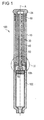
- Figures 1 , 2 and 6 show a drug delivery device 100 with a drive assembly.
- the drug delivery device 100 is a pen-type drug delivery device which may inject drugs.
- the drug delivery device 100 is a fixed dose device, in particular a device for dispensing fixed, non user-variable, for example constant, doses.
- the drug delivery device 100 comprises a medication containing cartridge 101 which is arranged in a cartridge holder 102.
- the cartridge 101 holds a medication 103.
- the drug delivery device 100 further comprises a needle device 104.
- the needle device 104 is arranged at the distal end of the cartridge holder 102 and is preferably secured to it.
- the medication 103 may be dispensed through the needle device 104.
- the medication 103 may comprise insulin, growth hormones, low molecular weight heparins, and/or their analogues and/or derivatives.
- the medication 103 may be a fluid.
- a bung 105 is arranged inside the cartridge 101.
- the bung 105 is capable of being displaced inside the cartridge 101.
- a displacement of the bung 105 in the distal direction relative to the cartridge 101 results in a dispensing of medication.
- the movement of the bung 105 is actuated by a piston rod 50.
- the piston rod acts on the bung 105 via a bearing 70.
- the bearing 70 is axially arranged between the piston rod 50 and the bung 105.
- the bearing 70 may be dispensed with.
- the drive assembly is arranged at the proximal end of the medication containing cartridge 101.
- the medication containing cartridge 101 is preferably secured to a housing 10 at the distal end side of the housing 10.
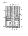
- the drive assembly comprises the housing 10. Furthermore, the drive assembly comprises a drive member 40 and a further drive member 20. Preferably, the drive member 40 is a rotation sleeve. Furthermore, the drive assembly comprises the piston rod 50. Additionally, the drive assembly comprises a biasing member 60 which is preferably arranged between the further drive member 20 and the housing 10. The biasing member 60 may exert a force on the further drive member 20 in axial direction during the delivery of medication. Preferably, the biasing member 60 comprises a compression spring. As can be seen in the embodiment of Figure 5 , the drive assembly may comprise a snap-in member 61 which is preferably arranged between the further drive member 20 and the housing 10 to prevent an undesired axial movement of the further drive member 20.
- the housing 10 extends between a proximal end 11 and a distal end 12.
- the housing 10 may have a hollow cylindrical shape.
- the housing 10 comprises a first section 14 and a second section 16.
- the first section 14 is shaped like a sleeve.
- the second section 16 is shaped like a disk.
- the second section 16 is fixedly coupled to the first section 14.
- the housing 10 may comprise coupling means arranged at the distal end 12.
- the coupling means on the distal end 12 may be for coupling the housing 10 with the cartridge holder 102.
- the cartridge holder 102 interacts with the second section 16.
- the second section 16 acts as an intermediate element for the cartridge holder 102 to obtain a defined position of the cartridge holder 102.
- a longitudinal axis A extends between the proximal end 11 and the distal end 12.
- the longitudinal axis A basically extends through the center of the housing 10.
- the surfaces of the housing 10 basically extend along the longitudinal axis A.
- the housing 10 may comprise an opening, for example to provide a display which may show the number of dispensed or remaining doses of drug.
- the further drive member 20 preferably comprises an inner thread 21 which is extending in axial direction ( Figure 2 ).
- the inner thread 21 of the further drive member 20 follows a helical path with a centre axis of this path being the longitudinal axis A or an axis parallel to the longitudinal axis A.
- the rotation sleeve has an outer thread which engages with an engaging device of the further drive member 20.
- the further drive member 20 is axially displaceable with respect to the housing 10 and thereby enables a rotational movement of the rotation sleeve via the thread 21.
- any axial movement of the further drive member 20 relative to the rotation sleeve is converted into a rotational movement of the rotation sleeve.
- the further drive member 20 is preferably splined to the housing 10.
- the further drive member 20 preferably comprises at least one groove which is extending in axial direction.
- the groove is in engagement with the housing 10 for example with a tab.
- the tab is a part of the housing 10 or is locked to the housing 10.
- the groove being in engagement with the housing 10 may ensure an axial movement of the further drive member 20 relative to the housing 10.
- the housing 10 comprises a groove and the further drive member 20 has a tab being in engagement with the groove.
- the further drive member 20 preferably comprises coupling means for coupling the further drive member 20 with further elements.
- a dose button 24 is coupled to the further drive member 20.
- the dose button 24 may transfer a force exerted on the dose button 24 in distal or proximal direction to the further drive member 20.
- the dose button 24 may be pushed in the distal direction with respect to the housing 10 for administering a dose of medication.
- the dose button 24 may be pulled in the proximal direction with respect to the housing 10 for setting a dose of medication.
- the dose button 24 may be pulled in the proximal direction with the support of the biasing member 60.
- the force for administering a dose of medication is exerted directly on the further drive member 20. In this embodiment no separate dose button 24 is needed.
- the force may be a force being exerted manually on the dose button 24 by a user.
- the rotation sleeve has an outer surface 42.
- the outer surface 42 comprises an engaging device 43 which extends in axial direction and is in engagement with the thread 21 of the further drive member 20.
- the thread 21 and the engaging device 43 enable a transformation of an axial movement of the further drive member 20 into a rotational movement of the rotation sleeve.
- a rotational movement of the rotation sleeve can be carried out in a first direction D1 or in a second direction D2 which is counterclockwise to the first direction D1 ( Figure 3 ).
- a rotational movement of the rotation sleeve in the first direction D1 can be achieved by a movement of the further drive member 20 in a distal direction D3 relative to the housing 10 which is a distal movement of the further drive member 20.
- a rotational movement of the rotation sleeve in the second direction D2 can be achieved by an axial proximal movement of the further drive member 20 relative to the housing 10 in a proximal direction D4.
- the rotation sleeve further comprises a protrusion 44 extending in radial direction, e.g. a radially outwardly directed flange.
- a protrusion 44 extending in radial direction between the first section 14 and the second section 16 of the housing 10 (see Figure 3 ) an axial movement of the rotation sleeve relative to the housing 10 may be prevented. Therefore, the rotation sleeve carries out a rotational movement in the first direction D1 and in the second direction D2 only.
- the drive member 40 has a guide piece 45 protruding from an inner surface of the drive member 40 in radial direction, in particular towards the longitudinal axis A of the housing 10.
- the guide piece 45 is in engagement with the piston rod 50.
- the piston rod 50 has an outer surface 52.
- a guide track 53 is arranged on the outer surface 52 of the piston rod 50.
- the guide piece 45 of the drive member 40 is arranged in the guide track 53.
- the guide piece 45 is moveable in the guide track 53. The engagement of the guide piece 45 and the guide track 53 enables a secure slotted link between the drive member 40 and the piston rod 50.
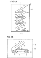
- the guide piece 45 has a circular square section, as shown in Figures 4 and 4A . This allows a smooth and secure movement of the guide piece 45 in the guide track 53.
- Figure 4 shows the guide track 53 of the piston rod 50 in a detailed view.
- the guide piece45 and the guide track 53 are engaged.
- the guide track 53 runs on the outer surface 52 of the piston rod 50 which may be curved.
- the path of the guide track 53 is shown in plan view in Figure 4 .
- the guide track 53 may be moved along the guide piece 45 when the piston rod 50 is moved in the distal direction.
- the guide track 53 is preferably formed as a zigzag-like line on the outer surface 52 of the piston rod 50.
- the zigzag-like line is extending in axial direction, in particular as far as a main direction of extent of the guide track 53 is concerned.
- the guide track 53 has consecutive segments. Each of the consecutive segments of the guide track 53 comprises an oblique section 54. Furthermore, each of the consecutive segments of the guide track 53 comprises a perpendicular section 55. Each of the consecutive segments of one of the oblique sections 54 and one of the perpendicular sections 55 is formed like a "V". A single of these consecutive segments formed as a "V" is shown in Fig. 4B , 4C and 4D .
- the perpendicular sections 55 extend expediently perpendicular or essentially perpendicular relative to the longitudinal axis A and are acting as dose setting sections.
- the guide piece 45 travels in the perpendicular sections 54 during dose setting.
- the oblique sections 54 extend obliquely relative to the longitudinal axis A and are acting as dose dispensing sections. If the section 55 of a segment is oblique with respect to the axis A, the section 54 of that segment is preferably more oblique with respect to the axis A. It is, however, preferred that the sections 55 extend perpendicular with respect to the axis A.
- the guide piece 45 travels in the oblique sections 54 during dose dispensing.
- the oblique sections 54 define first paths P1, and the perpendicular sections 55 define second paths P2.
- the first paths P1 and the second paths P2 are designed to guide the guide piece 45.
- the oblique sections 54 and the perpendicular sections 55 are alternatingly disposed along the guide track 53 thereby forming the zigzag-like line for the guide track 53.
- the oblique section 54 has a distal final area 56 and a proximal final area 58.
- the course of the pitch of the oblique section 54 is that it decreases from the distal final area 56 to the proximal final area 58. That means that the oblique section 54 forms a concave function with respect to the representation in Figure 4 .
- the pitch of the oblique section 54 decreases continuously from the distal final area 56 to the proximal final area 58.
- the pitch of the oblique section 54 may decrease in limited areas between the distal final area 56 and the proximal final area 58.
- the piston rod 50 is splined to the housing 10. This facilitates a precise movement of the piston rod 50 in the axial direction without a rotation.
- an end section 59 is arranged directly at the proximal end of the uppermost second section 54 relative to Figure 4A . This makes it possible to prevent already a further setting movement of the piston rod 50 immediately after the last allowed dose has been dispensed. In the embodiment of Figure 4 , a subsequent dose setting movement is allowed, whereas the subsequent dose dispensing movement which would have to be performed is prevented.
- the guide piece 45 has a quasi-circular square section with an oblique cut at its proximal end.
- the angles of the oblique cuts are different in Figures 4B and 4C .
- the oblique cut allows a smooth and secure movement of the guide piece 45 in the guide track 53.
- the guide piece 45 has a quadrilateral square section. This shape of the guide piece 45 allows a secure movement of the guide piece 45 in the guide track 53.
- the first section 55 of the guide track 53 has a wedge-shaped projection 62 extending from the proximal wall of the perpendicular section 55.
- the projection 62 may be elastically deformable.
- the projection 62 reduces the square section, in particular the axial extension of the perpendicular section 55.
- the perpendicular section 55 may taper in the direction from the right to the left in view of Figures 4B , 4C and 4D .
- the projection 62 is in mechanical cooperation with the guide piece 45.
- the shape of the guide piece 45 of Figures 4B , 4C and 4D in combination in particular with the wedge-shaped projection 62 may prevent an unintended backward movement of the guide piece 45 in the guide track 53.
- a recess 64 is arranged between the perpendicular section 55 and the oblique section 54 adjacent to the projection 62.
- the recess 64 increases the flexibility of the projection 62 in the case that the guide piece 45 passes the projection 62 during its movement from the perpendicular section 55 to the oblique section 54. Consequently, a reliable passing of the guide piece 45 from the perpendicular section 55 to the oblique section 54 is possible without an interference of the prevention of the movement of the guide piece 45 from the oblique section 54 back to the perpendicular section 55.
- An actuation of the dose button 24, preferably a manually actuated movement of the dose button 24 with respect to the housing 10, causes linear displacement of the further drive member 20 which is part of the drive assembly.
- the further drive member 20 is linearly displaced in the distal direction, for example towards the distal end 12, and the needle device 104 respectively.
- the linear displacement of the further drive member 20 causes a rotational movement of the rotation sleeve in one of the first or second directions D1, D2 and a corresponding displacement of the piston rod 50.
- the user removes the snap-in element 61 and pulls the further drive member 20 in the proximal direction D4.
- This movement may be supported by the biasing member 60.
- the guide piece 45 of the rotation sleeve travels along the perpendicular section 55 of the guide track 53 on the second path P2 from the proximal final area 58 of the preceding oblique section 55 to the distal final area 56 of the subsequent oblique section 55.
- the movement of the guide piece 45 is restricted by two walls limiting the guide track 53.
- the guide piece 45 travels along the second path P2 until the guide piece 45 comes into contact with a the wall of the guide track 53, e.g. a wall at the left of the guide track 53, near or in the distal final area 56 between the perpendicular section 55 and the oblique section 54 of the current segment of the guide track 53.
- the piston rod 50 can not move in axial direction relative to the housing 10 during the dose setting process.
- the dose setting process is completed.
- the user pushes the further drive member 20 of the drug delivery device 100 in the distal direction D3.
- the movement of the further drive member 20 in the distal direction D3 is terminated when the snap-in element 61 comes into engagement with the housing 10 as shown in Figure 5 .
- the guide piece 45 of the rotation sleeve follows the first path P1 of the oblique section 55 from the distal final area 56 to the proximal final area 58.
- the movement of the guide piece 45 is again restricted by the two walls limiting the guide track 53.
- the guide piece 45 now cooperates with the wall right of the guide track 53. Therefore, the guide piece 45 travels along the first path P1 until the guide piece 45 reaches the proximal final area 58 between the oblique section 54 of the current segment and the perpendicular section 55 of a subsequent segment of the guide track 53.
- the piston rod 50 is moved in distal direction due to the guide piece 45 interacting with the wall of the oblique section 54.
- medication 103 may be dispensed from the medication containing cartridge 101.
- the pitch of the oblique section 54 decreases from the distal final area 56 to the proximal final area 58 of the current oblique section 54 the velocity of the injection decreases during the run of the guide piece 45 in the current oblique section 54.
- the injection stress in the end of the dose delivery phase decreases.
- the dispersion period of the medication decreases due to that the injected dose medication decreases in the end of the dose delivery phase.
- the time in which the drug delivery device remains in the biological tissue of the user during the dosing of medication may be kept small. Furthermore, a leakage of drug from the drug delivery device in the end of the dose delivery phase may be prevented. Due to the decreasing velocity of the injection during the dose delivery phase the injection force may decrease simultaneously. As the biasing member 60 exerts a force on the further drive member 20 the decreasing injection force may be compensated by the biasing member 60 and the effective injection force may be kept constant.
- a user may carry out the described steps of setting and dispensing a dose in consecutive steps, wherein the guide piece 45 of the rotation sleeve is guided by the consecutive segment with one of the oblique sections 54 and one of the perpendicular sections 55.
- the guide piece 45 of the rotation sleeve is guided by the consecutive segment with one of the oblique sections 54 and one of the perpendicular sections 55.
Claims (15)
- Ensemble d'entraînement pour un dispositif d'administration de médicament (100), comprenant :- un boîtier (10) comportant une extrémité proximale (11) et une extrémité distale (12), et un axe longitudinal (A) s'étendant entre l'extrémité proximale (11) et l'extrémité distale (12),- un organe d'entraînement (40), et- une tige de piston (50),caractérisé en ce que
la tige de piston (50) est mobile axialement par rapport au boîtier (10), la tige de piston (50) comprenant une piste de guidage (53), et l'organe d'entraînement (40) comprenant une pièce de guidage (45) disposée dans la piste de guidage (53), et la piste de guidage (53) comprenant au moins une section (54) qui est oblique par rapport à l'axe longitudinal (A) et qui définit un déplacement de la tige de piston par rapport au boîtier pour la distribution d'une seule dose préétablie de substance médicamenteuse lors d'un déplacement relatif entre la pièce de guidage (45) et la tige de piston (50) lorsque la pièce de guidage (45) coopère avec la section oblique (54) entre une zone finale distale (56) de la section oblique (54) et une zone finale proximale (58) de la section oblique (54),
et
le pas de l'au moins une section oblique (54) variant de la zone finale distale (56) à la zone finale proximale (58). - Ensemble d'entraînement selon la revendication 1, dans lequel le pas de l'au moins une section oblique (54) diminue de la zone finale distale (56) à la zone finale proximale (58).
- Ensemble d'entraînement selon la revendication 1 ou 2, dans lequel la piste de guidage (53) comprend au moins une autre section (55) qui est perpendiculaire par rapport à l'axe longitudinal (A) et conçue pour établir ou sélectionner une dose de substance médicamenteuse lors du déplacement relatif de la pièce de guidage (45) dans la section perpendiculaire (55).
- Ensemble d'entraînement selon la revendication 3, dans lequel la piste de guidage (53) comprend une pluralité de sections obliques (54) et de sections perpendiculaires (55), et chacune des sections perpendiculaires (55) est disposée entre deux sections obliques (54) de manière à ce que la piste de guidage (53) forme une ligne continue.
- Ensemble d'entraînement selon l'une des revendications précédentes, dans lequel la section oblique (54) est conçue pour convertir un déplacement de l'organe d'entraînement (40) par rapport au boîtier (10) en un déplacement axial de la tige de piston (50).
- Ensemble d'entraînement selon l'une des revendications 3 à 5, dans lequel la section perpendiculaire (55) est conçue pour empêcher un déplacement axial de la tige de piston (50).
- Ensemble d'entraînement selon l'une des revendications précédentes, dans lequel un autre organe d'entraînement (20) est mobile par rapport au boîtier (10), et l'organe d'entraînement (40) est en coopération mécanique avec l'autre organe d'entraînement (20) afin d'être mobile par rapport au boîtier (10) lorsque l'autre organe d'entraînement (20) est déplacé par rapport à l'organe d'entraînement (40), et un organe de sollicitation (60) étant conçu pour exercer une force sur l'autre organe d'entraînement (20) dans la direction axiale lors de l'administration de substance médicamenteuse lors du déplacement relatif de la pièce de guidage (45) dans la section oblique (54) dans la zone finale proximale (58) de la section oblique (54).
- Ensemble d'entraînement selon la revendication 7, dans lequel l'organe de sollicitation (60) comprend un ressort de compression.
- Ensemble d'entraînement selon la revendication 7 ou 8, dans lequel l'autre organe d'entraînement (20) est mobile axialement par rapport au boîtier (10), et l'organe d'entraînement (40) est un manchon rotatif qui est en coopération mécanique avec l'autre organe d'entraînement (20) afin d'être rotatif par rapport au boîtier (10) lorsque l'autre organe d'entraînement (20) est déplacé dans la direction axiale par rapport au manchon rotatif.
- Ensemble d'entraînement selon la revendication 9, dans lequel la tige de piston (50) est en coopération mécanique avec le manchon rotatif afin d'être mobile dans la direction distale par rapport au boîtier (10) lorsque le manchon rotatif tourne dans une première direction (D1) et d'être stationnaire dans la direction axiale par rapport au boîtier (10) lorsque le manchon rotatif tourne dans une seconde direction (D2) opposée à la première direction (D1).
- Ensemble d'entraînement selon la revendication 10, dans lequel la section oblique (54) est conçue pour convertir un mouvement de rotation du manchon rotatif dans la première direction (D1) en un déplacement axial de la tige de piston (50).
- Ensemble d'entraînement selon l'une des revendications 9 à 11, dans lequel les sections perpendiculaires (55) s'étendent perpendiculairement à l'axe longitudinal (A), ce qui limite le mouvement de rotation du manchon rotatif.
- Ensemble d'entraînement selon l'une des revendications 9 à 12, dans lequel la piste de guidage (53) et la pièce de guidage (45) sont conçues pour coopérer à la façon d'un guide à fente.
- Ensemble d'entraînement selon l'une des revendications précédentes, dans lequel la piste de guidage (53) forme une ligne en zigzag sur une surface extérieure (52) de la tige de piston (50), et la ligne en zigzag s'étend dans la direction axiale.
- Dispositif d'administration de médicament (100) comportant un ensemble d'entraînement selon l'une des revendications précédentes, dans lequel une cartouche (102) contenant une substance médicamenteuse est accouplée à la tige de piston (50) de façon à distribuer la substance médicamenteuse (103).
Priority Applications (1)
| Application Number | Priority Date | Filing Date | Title |
|---|---|---|---|
| EP10800903.6A EP2509663B1 (fr) | 2009-12-07 | 2010-12-06 | Ensemble de commande pour dispositif d'administration de médicaments et dispositif d'administration de médicaments |
Applications Claiming Priority (3)
| Application Number | Priority Date | Filing Date | Title |
|---|---|---|---|
| EP09178215 | 2009-12-07 | ||
| EP10800903.6A EP2509663B1 (fr) | 2009-12-07 | 2010-12-06 | Ensemble de commande pour dispositif d'administration de médicaments et dispositif d'administration de médicaments |
| PCT/EP2010/068916 WO2011069936A1 (fr) | 2009-12-07 | 2010-12-06 | Ensemble entraînement pour dispositif d'administration de médicament, et dispositif d'administration de médicament |
Publications (2)
| Publication Number | Publication Date |
|---|---|
| EP2509663A1 EP2509663A1 (fr) | 2012-10-17 |
| EP2509663B1 true EP2509663B1 (fr) | 2015-01-21 |
Family
ID=42455318
Family Applications (1)
| Application Number | Title | Priority Date | Filing Date |
|---|---|---|---|
| EP10800903.6A Active EP2509663B1 (fr) | 2009-12-07 | 2010-12-06 | Ensemble de commande pour dispositif d'administration de médicaments et dispositif d'administration de médicaments |
Country Status (11)
| Country | Link |
|---|---|
| US (1) | US9022993B2 (fr) |
| EP (1) | EP2509663B1 (fr) |
| JP (1) | JP5816191B2 (fr) |
| CN (1) | CN102695532B (fr) |
| AU (1) | AU2010330033B2 (fr) |
| BR (1) | BR112012013767A2 (fr) |
| CA (1) | CA2779389A1 (fr) |
| DK (1) | DK2509663T3 (fr) |
| HK (1) | HK1176898A1 (fr) |
| IL (1) | IL220169A (fr) |
| WO (1) | WO2011069936A1 (fr) |
Families Citing this family (26)
| Publication number | Priority date | Publication date | Assignee | Title |
|---|---|---|---|---|
| KR20040103930A (ko) | 2002-02-11 | 2004-12-09 | 앤태어스 파머, 인코퍼레이티드 | 피내 주사기 |
| BRPI0614025A2 (pt) | 2005-01-24 | 2012-12-25 | Antares Pharma Inc | injetores de jato |
| US9144648B2 (en) | 2006-05-03 | 2015-09-29 | Antares Pharma, Inc. | Injector with adjustable dosing |
| US8251947B2 (en) | 2006-05-03 | 2012-08-28 | Antares Pharma, Inc. | Two-stage reconstituting injector |
| EP2268342B1 (fr) | 2008-03-10 | 2015-09-16 | Antares Pharma, Inc. | Dispositif de sécurité pour injecteur |
| JP5611208B2 (ja) | 2008-08-05 | 2014-10-22 | アンタレス・ファーマ・インコーポレーテッド | 多数回服用量の注射装置 |
| AU2010226442A1 (en) | 2009-03-20 | 2011-10-13 | Antares Pharma, Inc. | Hazardous agent injection system |
| US20120283652A1 (en) * | 2009-09-30 | 2012-11-08 | Sanofi-Aventis Deutschland Gmbh | Assembly and Piston Rod for a Drug Delivery Device |
| EP2399635A1 (fr) | 2010-06-28 | 2011-12-28 | Sanofi-Aventis Deutschland GmbH | Auto-injecteur |
| DK2627382T3 (en) * | 2010-10-11 | 2016-07-25 | Shl Group Ab | Drug delivery devices |
| EP2468333A1 (fr) | 2010-12-21 | 2012-06-27 | Sanofi-Aventis Deutschland GmbH | Auto-injecteur |
| USRE48593E1 (en) | 2010-12-21 | 2021-06-15 | Sanofi-Aventis Deutschland Gmbh | Auto-injector |
| AU2012269060B2 (en) * | 2011-06-17 | 2016-07-14 | Sanofi-Aventis Deutschland Gmbh | Cartridge holder assembly for drug delivery devices |
| US8496619B2 (en) | 2011-07-15 | 2013-07-30 | Antares Pharma, Inc. | Injection device with cammed ram assembly |
| US9220660B2 (en) | 2011-07-15 | 2015-12-29 | Antares Pharma, Inc. | Liquid-transfer adapter beveled spike |
| US8834449B2 (en) | 2012-01-23 | 2014-09-16 | Ikomed Technologies, Inc. | Mixing syringe |
| US9751056B2 (en) | 2012-01-23 | 2017-09-05 | Merit Medical Systems, Inc. | Mixing syringe |
| JP6165786B2 (ja) | 2012-03-06 | 2017-07-19 | アンタレス・ファーマ・インコーポレーテッド | 離脱力特徴を備える充填シリンジ |
| CN104487114A (zh) | 2012-04-06 | 2015-04-01 | 安塔雷斯药品公司 | 针头辅助喷射注射给予睾酮组合物 |
| WO2013169800A1 (fr) | 2012-05-07 | 2013-11-14 | Antares Pharma, Inc. | Dispositif d'injection ayant un ensemble piston à came |
| EP2953667B1 (fr) | 2013-02-11 | 2019-10-23 | Antares Pharma, Inc. | Dispositif d'injection à jet assistée par aiguille ayant une force de déclenchement réduite |
| WO2014164786A1 (fr) | 2013-03-11 | 2014-10-09 | Madsen Patrick | Injecteur de dose avec système à pignon |
| WO2014165136A1 (fr) | 2013-03-12 | 2014-10-09 | Antares Pharma, Inc. | Seringues pré-remplies à volume constant et leurs trousses |
| EP2823841A1 (fr) | 2013-07-09 | 2015-01-14 | Sanofi-Aventis Deutschland GmbH | Auto-injecteur |
| EP2923714A1 (fr) | 2014-03-28 | 2015-09-30 | Sanofi-Aventis Deutschland GmbH | Auto-injecteur declenché par contact avec la peau |
| US11577028B2 (en) * | 2021-01-20 | 2023-02-14 | Becton, Dickinson And Company | Syringe with a bidirectional plunger advancing mechanism for a micro-dosing syringe pump |
Family Cites Families (8)
| Publication number | Priority date | Publication date | Assignee | Title |
|---|---|---|---|---|
| US4475905A (en) * | 1982-09-30 | 1984-10-09 | Himmelstrup Anders B | Injection device |
| US5256152A (en) * | 1991-10-29 | 1993-10-26 | Marks Lloyd A | Safety needle and method of using same |
| GB9300567D0 (en) * | 1993-01-12 | 1993-03-03 | Owen Mumford Ltd | Improvements relating to devices for generating intermittent motion |
| DE19822031C2 (de) | 1998-05-15 | 2000-03-23 | Disetronic Licensing Ag | Autoinjektionsgerät |
| SE9901366D0 (sv) * | 1999-04-16 | 1999-04-16 | Pharmacia & Upjohn Ab | Injector device and method for its operation |
| US9486581B2 (en) * | 2002-09-11 | 2016-11-08 | Becton, Dickinson And Company | Injector device with force lock-out and injection rate limiting mechanisms |
| CN101903059B (zh) * | 2007-12-20 | 2013-06-19 | 诺沃-诺迪斯克有限公司 | 用于输送固定剂量液态药物的注射装置 |
| GB0808389D0 (en) * | 2008-05-09 | 2008-06-18 | Owen Mumford Ltd | Electrically actuated injector |
-
2010
- 2010-12-06 CA CA2779389A patent/CA2779389A1/fr not_active Abandoned
- 2010-12-06 AU AU2010330033A patent/AU2010330033B2/en not_active Ceased
- 2010-12-06 US US13/509,602 patent/US9022993B2/en active Active
- 2010-12-06 WO PCT/EP2010/068916 patent/WO2011069936A1/fr active Application Filing
- 2010-12-06 CN CN201080060957.5A patent/CN102695532B/zh not_active Expired - Fee Related
- 2010-12-06 JP JP2012542483A patent/JP5816191B2/ja not_active Expired - Fee Related
- 2010-12-06 DK DK10800903.6T patent/DK2509663T3/en active
- 2010-12-06 EP EP10800903.6A patent/EP2509663B1/fr active Active
- 2010-12-06 BR BR112012013767A patent/BR112012013767A2/pt not_active IP Right Cessation
-
2012
- 2012-06-04 IL IL220169A patent/IL220169A/en not_active IP Right Cessation
-
2013
- 2013-04-15 HK HK13104516.2A patent/HK1176898A1/xx not_active IP Right Cessation
Also Published As
| Publication number | Publication date |
|---|---|
| IL220169A (en) | 2014-06-30 |
| HK1176898A1 (en) | 2013-08-09 |
| AU2010330033B2 (en) | 2014-10-23 |
| CN102695532B (zh) | 2015-02-18 |
| DK2509663T3 (en) | 2015-04-27 |
| CA2779389A1 (fr) | 2011-06-16 |
| JP2013512744A (ja) | 2013-04-18 |
| IL220169A0 (en) | 2012-07-31 |
| US20130018327A1 (en) | 2013-01-17 |
| AU2010330033A1 (en) | 2012-06-21 |
| CN102695532A (zh) | 2012-09-26 |
| EP2509663A1 (fr) | 2012-10-17 |
| WO2011069936A1 (fr) | 2011-06-16 |
| US9022993B2 (en) | 2015-05-05 |
| BR112012013767A2 (pt) | 2016-04-26 |
| JP5816191B2 (ja) | 2015-11-18 |
Similar Documents
| Publication | Publication Date | Title |
|---|---|---|
| EP2509663B1 (fr) | Ensemble de commande pour dispositif d'administration de médicaments et dispositif d'administration de médicaments | |
| EP3192548B1 (fr) | Ensemble de commande pour dispositif d'administration de médicaments et ledit dispositif | |
| EP2552519B1 (fr) | Ensemble tige de piston pour dispositif d'administration de médicament | |
| EP2482890B1 (fr) | Élément de bouton pour la commande d'un assemblage de commande | |
| EP2531241B1 (fr) | Assemblage pour dispositif d'administration de médicaments et dispositif d'administration de médicaments | |
| EP2482897B1 (fr) | Assemblage et tige de piston pour dispositif d'administration de médicaments | |
| US9802004B2 (en) | Drive mechanism for a medication delivery device and medication delivery device | |
| WO2010139645A1 (fr) | Mécanisme doseur pour dispositif de distribution de médicament | |
| EP2482889B1 (fr) | Assemblage pour dispositif d'administration de médicaments | |
| EP2482900B1 (fr) | Assemblage pour dispositif d'administration de médicaments | |
| EP2624894B1 (fr) | Mécanisme d'entraînement pour un dispositif d'administration de médicament et dispositif d'administration de médicament |
Legal Events
| Date | Code | Title | Description |
|---|---|---|---|
| PUAI | Public reference made under article 153(3) epc to a published international application that has entered the european phase |
Free format text: ORIGINAL CODE: 0009012 |
|
| 17P | Request for examination filed |
Effective date: 20120709 |
|
| AK | Designated contracting states |
Kind code of ref document: A1 Designated state(s): AL AT BE BG CH CY CZ DE DK EE ES FI FR GB GR HR HU IE IS IT LI LT LU LV MC MK MT NL NO PL PT RO RS SE SI SK SM TR |
|
| AX | Request for extension of the european patent |
Extension state: BA ME |
|
| REG | Reference to a national code |
Ref country code: HK Ref legal event code: DE Ref document number: 1176898 Country of ref document: HK |
|
| GRAP | Despatch of communication of intention to grant a patent |
Free format text: ORIGINAL CODE: EPIDOSNIGR1 |
|
| INTG | Intention to grant announced |
Effective date: 20140813 |
|
| GRAS | Grant fee paid |
Free format text: ORIGINAL CODE: EPIDOSNIGR3 |
|
| GRAA | (expected) grant |
Free format text: ORIGINAL CODE: 0009210 |
|
| AK | Designated contracting states |
Kind code of ref document: B1 Designated state(s): AL AT BE BG CH CY CZ DE DK EE ES FI FR GB GR HR HU IE IS IT LI LT LU LV MC MK MT NL NO PL PT RO RS SE SI SK SM TR |
|
| AX | Request for extension of the european patent |
Extension state: BA ME |
|
| REG | Reference to a national code |
Ref country code: GB Ref legal event code: FG4D |
|
| REG | Reference to a national code |
Ref country code: CH Ref legal event code: EP |
|
| REG | Reference to a national code |
Ref country code: IE Ref legal event code: FG4D |
|
| REG | Reference to a national code |
Ref country code: DE Ref legal event code: R096 Ref document number: 602010022024 Country of ref document: DE Effective date: 20150305 |
|
| REG | Reference to a national code |
Ref country code: AT Ref legal event code: REF Ref document number: 708864 Country of ref document: AT Kind code of ref document: T Effective date: 20150315 |
|
| REG | Reference to a national code |
Ref country code: DK Ref legal event code: T3 Effective date: 20150421 |
|
| REG | Reference to a national code |
Ref country code: NL Ref legal event code: VDEP Effective date: 20150121 |
|
| REG | Reference to a national code |
Ref country code: AT Ref legal event code: MK05 Ref document number: 708864 Country of ref document: AT Kind code of ref document: T Effective date: 20150121 |
|
| REG | Reference to a national code |
Ref country code: LT Ref legal event code: MG4D |
|
| PG25 | Lapsed in a contracting state [announced via postgrant information from national office to epo] |
Ref country code: BG Free format text: LAPSE BECAUSE OF FAILURE TO SUBMIT A TRANSLATION OF THE DESCRIPTION OR TO PAY THE FEE WITHIN THE PRESCRIBED TIME-LIMIT Effective date: 20150421 Ref country code: LT Free format text: LAPSE BECAUSE OF FAILURE TO SUBMIT A TRANSLATION OF THE DESCRIPTION OR TO PAY THE FEE WITHIN THE PRESCRIBED TIME-LIMIT Effective date: 20150121 Ref country code: SE Free format text: LAPSE BECAUSE OF FAILURE TO SUBMIT A TRANSLATION OF THE DESCRIPTION OR TO PAY THE FEE WITHIN THE PRESCRIBED TIME-LIMIT Effective date: 20150121 Ref country code: FI Free format text: LAPSE BECAUSE OF FAILURE TO SUBMIT A TRANSLATION OF THE DESCRIPTION OR TO PAY THE FEE WITHIN THE PRESCRIBED TIME-LIMIT Effective date: 20150121 Ref country code: HR Free format text: LAPSE BECAUSE OF FAILURE TO SUBMIT A TRANSLATION OF THE DESCRIPTION OR TO PAY THE FEE WITHIN THE PRESCRIBED TIME-LIMIT Effective date: 20150121 Ref country code: NO Free format text: LAPSE BECAUSE OF FAILURE TO SUBMIT A TRANSLATION OF THE DESCRIPTION OR TO PAY THE FEE WITHIN THE PRESCRIBED TIME-LIMIT Effective date: 20150421 Ref country code: ES Free format text: LAPSE BECAUSE OF FAILURE TO SUBMIT A TRANSLATION OF THE DESCRIPTION OR TO PAY THE FEE WITHIN THE PRESCRIBED TIME-LIMIT Effective date: 20150121 |
|
| REG | Reference to a national code |
Ref country code: HK Ref legal event code: GR Ref document number: 1176898 Country of ref document: HK |
|
| PG25 | Lapsed in a contracting state [announced via postgrant information from national office to epo] |
Ref country code: IS Free format text: LAPSE BECAUSE OF FAILURE TO SUBMIT A TRANSLATION OF THE DESCRIPTION OR TO PAY THE FEE WITHIN THE PRESCRIBED TIME-LIMIT Effective date: 20150521 Ref country code: PL Free format text: LAPSE BECAUSE OF FAILURE TO SUBMIT A TRANSLATION OF THE DESCRIPTION OR TO PAY THE FEE WITHIN THE PRESCRIBED TIME-LIMIT Effective date: 20150121 Ref country code: LV Free format text: LAPSE BECAUSE OF FAILURE TO SUBMIT A TRANSLATION OF THE DESCRIPTION OR TO PAY THE FEE WITHIN THE PRESCRIBED TIME-LIMIT Effective date: 20150121 Ref country code: NL Free format text: LAPSE BECAUSE OF FAILURE TO SUBMIT A TRANSLATION OF THE DESCRIPTION OR TO PAY THE FEE WITHIN THE PRESCRIBED TIME-LIMIT Effective date: 20150121 Ref country code: RS Free format text: LAPSE BECAUSE OF FAILURE TO SUBMIT A TRANSLATION OF THE DESCRIPTION OR TO PAY THE FEE WITHIN THE PRESCRIBED TIME-LIMIT Effective date: 20150121 Ref country code: GR Free format text: LAPSE BECAUSE OF FAILURE TO SUBMIT A TRANSLATION OF THE DESCRIPTION OR TO PAY THE FEE WITHIN THE PRESCRIBED TIME-LIMIT Effective date: 20150422 Ref country code: AT Free format text: LAPSE BECAUSE OF FAILURE TO SUBMIT A TRANSLATION OF THE DESCRIPTION OR TO PAY THE FEE WITHIN THE PRESCRIBED TIME-LIMIT Effective date: 20150121 |
|
| REG | Reference to a national code |
Ref country code: DE Ref legal event code: R097 Ref document number: 602010022024 Country of ref document: DE |
|
| PG25 | Lapsed in a contracting state [announced via postgrant information from national office to epo] |
Ref country code: EE Free format text: LAPSE BECAUSE OF FAILURE TO SUBMIT A TRANSLATION OF THE DESCRIPTION OR TO PAY THE FEE WITHIN THE PRESCRIBED TIME-LIMIT Effective date: 20150121 Ref country code: SK Free format text: LAPSE BECAUSE OF FAILURE TO SUBMIT A TRANSLATION OF THE DESCRIPTION OR TO PAY THE FEE WITHIN THE PRESCRIBED TIME-LIMIT Effective date: 20150121 Ref country code: CZ Free format text: LAPSE BECAUSE OF FAILURE TO SUBMIT A TRANSLATION OF THE DESCRIPTION OR TO PAY THE FEE WITHIN THE PRESCRIBED TIME-LIMIT Effective date: 20150121 Ref country code: RO Free format text: LAPSE BECAUSE OF FAILURE TO SUBMIT A TRANSLATION OF THE DESCRIPTION OR TO PAY THE FEE WITHIN THE PRESCRIBED TIME-LIMIT Effective date: 20150121 |
|
| REG | Reference to a national code |
Ref country code: FR Ref legal event code: PLFP Year of fee payment: 6 |
|
| PLBE | No opposition filed within time limit |
Free format text: ORIGINAL CODE: 0009261 |
|
| STAA | Information on the status of an ep patent application or granted ep patent |
Free format text: STATUS: NO OPPOSITION FILED WITHIN TIME LIMIT |
|
| 26N | No opposition filed |
Effective date: 20151022 |
|
| PG25 | Lapsed in a contracting state [announced via postgrant information from national office to epo] |
Ref country code: IT Free format text: LAPSE BECAUSE OF FAILURE TO SUBMIT A TRANSLATION OF THE DESCRIPTION OR TO PAY THE FEE WITHIN THE PRESCRIBED TIME-LIMIT Effective date: 20150121 |
|
| PGFP | Annual fee paid to national office [announced via postgrant information from national office to epo] |
Ref country code: CH Payment date: 20151211 Year of fee payment: 6 Ref country code: DK Payment date: 20151210 Year of fee payment: 6 |
|
| PG25 | Lapsed in a contracting state [announced via postgrant information from national office to epo] |
Ref country code: SI Free format text: LAPSE BECAUSE OF FAILURE TO SUBMIT A TRANSLATION OF THE DESCRIPTION OR TO PAY THE FEE WITHIN THE PRESCRIBED TIME-LIMIT Effective date: 20150121 |
|
| PG25 | Lapsed in a contracting state [announced via postgrant information from national office to epo] |
Ref country code: BE Free format text: LAPSE BECAUSE OF FAILURE TO SUBMIT A TRANSLATION OF THE DESCRIPTION OR TO PAY THE FEE WITHIN THE PRESCRIBED TIME-LIMIT Effective date: 20150121 |
|
| PG25 | Lapsed in a contracting state [announced via postgrant information from national office to epo] |
Ref country code: MC Free format text: LAPSE BECAUSE OF FAILURE TO SUBMIT A TRANSLATION OF THE DESCRIPTION OR TO PAY THE FEE WITHIN THE PRESCRIBED TIME-LIMIT Effective date: 20150121 Ref country code: LU Free format text: LAPSE BECAUSE OF FAILURE TO SUBMIT A TRANSLATION OF THE DESCRIPTION OR TO PAY THE FEE WITHIN THE PRESCRIBED TIME-LIMIT Effective date: 20151206 |
|
| REG | Reference to a national code |
Ref country code: IE Ref legal event code: MM4A |
|
| PG25 | Lapsed in a contracting state [announced via postgrant information from national office to epo] |
Ref country code: IE Free format text: LAPSE BECAUSE OF NON-PAYMENT OF DUE FEES Effective date: 20151206 |
|
| REG | Reference to a national code |
Ref country code: FR Ref legal event code: PLFP Year of fee payment: 7 |
|
| PG25 | Lapsed in a contracting state [announced via postgrant information from national office to epo] |
Ref country code: HU Free format text: LAPSE BECAUSE OF FAILURE TO SUBMIT A TRANSLATION OF THE DESCRIPTION OR TO PAY THE FEE WITHIN THE PRESCRIBED TIME-LIMIT; INVALID AB INITIO Effective date: 20101206 Ref country code: SM Free format text: LAPSE BECAUSE OF FAILURE TO SUBMIT A TRANSLATION OF THE DESCRIPTION OR TO PAY THE FEE WITHIN THE PRESCRIBED TIME-LIMIT Effective date: 20150121 |
|
| PG25 | Lapsed in a contracting state [announced via postgrant information from national office to epo] |
Ref country code: CY Free format text: LAPSE BECAUSE OF FAILURE TO SUBMIT A TRANSLATION OF THE DESCRIPTION OR TO PAY THE FEE WITHIN THE PRESCRIBED TIME-LIMIT Effective date: 20150121 |
|
| REG | Reference to a national code |
Ref country code: DK Ref legal event code: EBP Effective date: 20161231 Ref country code: CH Ref legal event code: PL |
|
| PG25 | Lapsed in a contracting state [announced via postgrant information from national office to epo] |
Ref country code: MT Free format text: LAPSE BECAUSE OF FAILURE TO SUBMIT A TRANSLATION OF THE DESCRIPTION OR TO PAY THE FEE WITHIN THE PRESCRIBED TIME-LIMIT Effective date: 20150121 |
|
| PG25 | Lapsed in a contracting state [announced via postgrant information from national office to epo] |
Ref country code: LI Free format text: LAPSE BECAUSE OF NON-PAYMENT OF DUE FEES Effective date: 20161231 Ref country code: CH Free format text: LAPSE BECAUSE OF NON-PAYMENT OF DUE FEES Effective date: 20161231 |
|
| REG | Reference to a national code |
Ref country code: FR Ref legal event code: PLFP Year of fee payment: 8 |
|
| PG25 | Lapsed in a contracting state [announced via postgrant information from national office to epo] |
Ref country code: DK Free format text: LAPSE BECAUSE OF NON-PAYMENT OF DUE FEES Effective date: 20161231 |
|
| PG25 | Lapsed in a contracting state [announced via postgrant information from national office to epo] |
Ref country code: TR Free format text: LAPSE BECAUSE OF FAILURE TO SUBMIT A TRANSLATION OF THE DESCRIPTION OR TO PAY THE FEE WITHIN THE PRESCRIBED TIME-LIMIT Effective date: 20150121 Ref country code: MK Free format text: LAPSE BECAUSE OF FAILURE TO SUBMIT A TRANSLATION OF THE DESCRIPTION OR TO PAY THE FEE WITHIN THE PRESCRIBED TIME-LIMIT Effective date: 20150121 Ref country code: PT Free format text: LAPSE BECAUSE OF FAILURE TO SUBMIT A TRANSLATION OF THE DESCRIPTION OR TO PAY THE FEE WITHIN THE PRESCRIBED TIME-LIMIT Effective date: 20150121 |
|
| PG25 | Lapsed in a contracting state [announced via postgrant information from national office to epo] |
Ref country code: AL Free format text: LAPSE BECAUSE OF FAILURE TO SUBMIT A TRANSLATION OF THE DESCRIPTION OR TO PAY THE FEE WITHIN THE PRESCRIBED TIME-LIMIT Effective date: 20150121 |
|
| P01 | Opt-out of the competence of the unified patent court (upc) registered |
Effective date: 20230421 |
|
| PGFP | Annual fee paid to national office [announced via postgrant information from national office to epo] |
Ref country code: FR Payment date: 20230929 Year of fee payment: 14 |
|
| PGFP | Annual fee paid to national office [announced via postgrant information from national office to epo] |
Ref country code: GB Payment date: 20231012 Year of fee payment: 14 |
|
| PGFP | Annual fee paid to national office [announced via postgrant information from national office to epo] |
Ref country code: DE Payment date: 20231010 Year of fee payment: 14 |