EP2550421B1 - Cord winder of a window shade - Google Patents
Cord winder of a window shade Download PDFInfo
- Publication number
- EP2550421B1 EP2550421B1 EP11711307.6A EP11711307A EP2550421B1 EP 2550421 B1 EP2550421 B1 EP 2550421B1 EP 11711307 A EP11711307 A EP 11711307A EP 2550421 B1 EP2550421 B1 EP 2550421B1
- Authority
- EP
- European Patent Office
- Prior art keywords
- cord
- rotary roller
- support
- winding drum
- winder
- Prior art date
- Legal status (The legal status is an assumption and is not a legal conclusion. Google has not performed a legal analysis and makes no representation as to the accuracy of the status listed.)
- Not-in-force
Links
Images


Classifications
-
- E—FIXED CONSTRUCTIONS
- E06—DOORS, WINDOWS, SHUTTERS, OR ROLLER BLINDS IN GENERAL; LADDERS
- E06B—FIXED OR MOVABLE CLOSURES FOR OPENINGS IN BUILDINGS, VEHICLES, FENCES OR LIKE ENCLOSURES IN GENERAL, e.g. DOORS, WINDOWS, BLINDS, GATES
- E06B9/00—Screening or protective devices for wall or similar openings, with or without operating or securing mechanisms; Closures of similar construction
- E06B9/24—Screens or other constructions affording protection against light, especially against sunshine; Similar screens for privacy or appearance; Slat blinds
- E06B9/26—Lamellar or like blinds, e.g. venetian blinds
- E06B9/28—Lamellar or like blinds, e.g. venetian blinds with horizontal lamellae, e.g. non-liftable
- E06B9/30—Lamellar or like blinds, e.g. venetian blinds with horizontal lamellae, e.g. non-liftable liftable
- E06B9/32—Operating, guiding, or securing devices therefor
- E06B9/322—Details of operating devices, e.g. pulleys, brakes, spring drums, drives
-
- E—FIXED CONSTRUCTIONS
- E06—DOORS, WINDOWS, SHUTTERS, OR ROLLER BLINDS IN GENERAL; LADDERS
- E06B—FIXED OR MOVABLE CLOSURES FOR OPENINGS IN BUILDINGS, VEHICLES, FENCES OR LIKE ENCLOSURES IN GENERAL, e.g. DOORS, WINDOWS, BLINDS, GATES
- E06B9/00—Screening or protective devices for wall or similar openings, with or without operating or securing mechanisms; Closures of similar construction
- E06B9/24—Screens or other constructions affording protection against light, especially against sunshine; Similar screens for privacy or appearance; Slat blinds
- E06B9/40—Roller blinds
- E06B9/42—Parts or details of roller blinds, e.g. suspension devices, blind boxes
-
- E—FIXED CONSTRUCTIONS
- E06—DOORS, WINDOWS, SHUTTERS, OR ROLLER BLINDS IN GENERAL; LADDERS
- E06B—FIXED OR MOVABLE CLOSURES FOR OPENINGS IN BUILDINGS, VEHICLES, FENCES OR LIKE ENCLOSURES IN GENERAL, e.g. DOORS, WINDOWS, BLINDS, GATES
- E06B9/00—Screening or protective devices for wall or similar openings, with or without operating or securing mechanisms; Closures of similar construction
- E06B9/24—Screens or other constructions affording protection against light, especially against sunshine; Similar screens for privacy or appearance; Slat blinds
- E06B9/26—Lamellar or like blinds, e.g. venetian blinds
- E06B9/28—Lamellar or like blinds, e.g. venetian blinds with horizontal lamellae, e.g. non-liftable
- E06B9/30—Lamellar or like blinds, e.g. venetian blinds with horizontal lamellae, e.g. non-liftable liftable
- E06B9/32—Operating, guiding, or securing devices therefor
- E06B9/322—Details of operating devices, e.g. pulleys, brakes, spring drums, drives
- E06B2009/3225—Arrangements to aid the winding of cords rollers
Definitions
- the invention relates to a cord winder for a window covering device.
- a cord retractor is equipped with sun protection, concealment or decoration devices arranged in front of bay windows and designated as "window covering devices". These devices are venetian blind type, boat blind, pleated blind, bubble blind or "Roman Shade”.
- sun covering devices are venetian blind type, boat blind, pleated blind, bubble blind or "Roman Shade”.
- several corded reels are arranged in a box and can be driven simultaneously by a common drive shaft, using a manual winch or an electric motor.
- the cords are attached at one end to a load bar while the occultation, decoration or sun protection product is deployed in the space between the load bar and the box.
- the visible surface of the product is proportional to the course of the cord.
- cord reels intended for this type of device.
- a real breakthrough in this field is the introduction of cord reels having functionally a winding zone of the cord, a means of thrusting the turns wound to a wound coil storage area, zone in which the tension of the turns of the cord has become substantially zero.
- capstan effect By physical effect called “capstan effect", the tension of the cord on a drum tends to decrease between a newly wound turn and a coil formerly wound. However, this effect is insufficient to allow a regular thrust of many turns on a purely cylindrical winding drum. The originally wound coils tend to hang on the drum, and new turns can not be inserted by pushing them. There is overlap of the turns. To prevent such an overlap from occurring, it has been invented to accentuate the capstan effect by further causing a gradual or abrupt variation in the diameter of the winding drum.
- Cord reels are, for the most part, equipped with a conical profile winding drum in the winding area.
- patent 7159635 also discloses a means for movably securing the cord along the winding drum, as also described in the patent US7,370,683 .
- Such a false movement on the load bar can also occur in the absence of a winding or unwinding maneuver, and cause a rise of the cord in the reel and, for example, an overlap of turns. Such false movements can occur during cleaning periods of the premises or glazing.
- cord reels with absolutely complete reliability. This is particularly the case for window covering devices arranged between two sealed windows, for which the slightest failure of the cord winder is prohibited. In this case, the false movements are not to be feared, but the problems mentioned above can simply come from hard points appearing over time in the guideways of the device.
- the object of the invention is to provide a cord winder overcoming the above disadvantages and improving the cord reels known from the prior art.
- the invention improves the winding and unwinding of a blind suspension cord, avoiding any risk of entanglement thereof.
- the cord winder of a window cover device comprises a winding drum of a cord adapted to be rotated about a first axis of revolution, a means of guiding the cord towards the winding drum, the winding drum being rotatably mounted in a support.
- the winder comprises a rotary roller mounted on the support according to a second axis of revolution and comprises a friction zone in which at least one turn the cord, wound on the winding drum, is in contact with the rotary roller.
- the rotation of the rotary roller can be slaved to the rotation of the winding drum by a servo means.
- the servo means may comprise a first pinion integral in rotation with the winding drum, and engaged with a second pinion integral in rotation with the rotary roller.
- the rotary roller may apply pressure to at least a first turn of the cord wound on the winding drum, for example the first turn and another turn or the first turn and two other turns.
- the cord winder may comprise a means of orientation of the cord, secured to the support and disposed in the vicinity of the friction zone away from the guide means and less than two turns of cord a last turn in contact with the rotary roller.
- the number of turns of the friction zone may be independent of the state of winding or unwinding of the bead.
- a thrust means may act at least on the turns in contact with the rotary roller, away from the guide means.
- the thrust means may be a helical wall.
- the helical wall may be formed in a cylindrical bore of the support, said cylindrical bore containing at least the friction zone and the helical wall may be at least partially interrupted by a housing of the rotary roller.
- the rotary roller may comprise two shaft ends, belonging for example to a secondary shaft, guided in the support, in particular by two straight grooves formed in the support.
- Pressure means can push the rotating roller towards the drum.
- the pressure means may comprise an elastic member of the support in contact with a shaft end of the rotary roller.
- the rotary roller may comprise an elastomeric coating and / or a friction coating.
- At most five consecutive turns of the bead may be in tangential contact with the rotary roller.
- the cord can be guided towards the winding drum by a central face of a finger, engaged in the support or belonging to the support.
- the invention significantly improves the prior art window cover cord reels by the use of a rotary roller disposed in direct contact with the first winding turns of the cord.
- the figure 1 represents a cord winder 1 according to the invention, in isometric view. As described in the prior art, the cord winder is intended to wind a cord 40 and to be arranged in a box of a cover device of a window, not shown.
- It comprises a support 2, forming a first bearing, and a second bearing 3 connected to the support by a cradle 4.
- the support is fixed on a base 5.
- a frame 6 is mounted on the support to allow the assembly of several parts on the support.
- a winding drum 7 is supported by the support and the second bearing and is rotatable about a first axis of rotation AA '.
- the support also forms the base.
- the figure 2 represents a partial exploded view and isometric view of the corded winder, and the figure 3 represents an assembled view of the elements of the figure 2 .
- the winding drum comprises a first ring 8 and a second ring 9, coaxial with the first axis of rotation and engaged respectively in the first bearing and in the second bearing.
- These rings are smooth externally so as to rotate in the bearings, and are recessed in a polygonal bore 10 adapted to allow the engagement of a drive shaft 20 to transmit a rotational movement to the winding drum.
- the drive shaft has for example a hexagonal profile.
- the bearings are not necessary.
- the second bearing is not necessary because the centering of the winding drum on the first axis of rotation can be provided by the drive shaft.
- the support may not form a first bearing when the centering of the winding drum on the first axis of rotation is ensured by the drive shaft, provided that the support is positioned accurately with respect to the drum winding.
- the winding drum comprises a means 11 for attaching a bead to the winding drum, for example in the form of a hole enabling the locking of a knot formed on the bead once it has engaged in the hole .
- the bead attachment means is axially movable along the winding drum, while being locked in rotation relative thereto.
- a guiding means 12 for entering the cord into the reel for example an arrival hole of the cord guiding the cord towards the winding drum, is arranged on the base 5, in the vicinity of a finger 13.
- the finger 13 may comprise a first thrust means 13a of the cord, as described below.
- the first thrust means may comprise a shoulder, made on one end of the winding drum.
- the guiding means may comprise a small pulley or alternatively two rollers of moving and substantially perpendicular axes, to guide the entry of the cord into the cord winder while limiting friction.
- a rotary roller 14, rotatable about a second axis of rotation BB 'substantially parallel to the first axis of rotation, is disposed in the support in the vicinity of the winding drum, the guide means, and the first thrust means, as specified later.
- This rotary roller is mounted by fitting on a secondary shaft 15, having a first shaft end 15a and a second shaft end 15b of the secondary shaft.
- the rotary roller may be extended by axial pins forming the first shaft end and the second shaft end.
- the role of the rotary roller is to apply friction on the cord.
- a pressure means 16, preferably of elastic type, is such that the rotary roller applies pressure to one or more turns of the cord wound on the winding drum.
- one or more bead turns are both in circumferential contact with the winding drum and in tangential contact with the rotary roller, the tangential contact being of pressing type and causing friction on the bead.
- the pressure means exerts a thrust on the rotary roller so that it is returned to the winding drum in contact with the coiled turns of the cord.
- a first elastic element 16a (such as a steel strip) and a second elastic element 16b respectively bear elastically on the first end and the second end of the secondary shaft.
- the two elastic elements constitute the elastic pressure means 16 allowing the rotary roller to frictionally drive turns wound on the winding drum.
- a first pinion 17 is integral in rotation with the secondary shaft, while a second pinion 18 is integral in rotation with the drum. winding.
- the second pinion is for example mounted on a drum surface provided with a flat 19, preferably engaged in force on the scope of the drum provided with the flat 19.
- the first pinion meshes with the second pinion. The role of the gears is described below.
- An orientation means 21 of the cord is for example constituted by a cylindrical pin whose axis of the cylinder is oriented in a direction at least substantially radial to the winding drum.
- the orientation means is fixed on the support.
- the radial distance between the orienting means and the winding drum is much smaller than the diameter of the bead.
- This orientation means can be rotatably mounted around the radial direction. The role of the orientation means is described below.
- the figure 4 represents a profile view of the elements of the figure 2 , with partial assembly of the elements and schematic representation of the cord 40 wound on several turns and a reference 22 diagrammatically dotted line a path in the winder.
- first turn means a first bead turn in contact with the winding drum when moving on the bead from the guide means 12 to enter the cord into the winder.
- the winding zone 7a is therefore a winding drum portion comprising a first turn of the bead and including the friction zone 23 in which at least one turn of the bead is both in circumferential contact with the winding drum and in tangential contact with the rotary roller.
- the winding zone may have an axial length greater than the axial extension of the friction zone, as on the figure 4 .
- the winding zone preferably has a constant diameter.
- the secondary shaft and the rotary roller have a second axis of rotation B-B 'parallel to the first axis of rotation A-A'.
- the winding zone may have a regular and weak decrease in diameter (a few hundredths of a millimeter per millimeter) when approaching the intermediate zone. This slightly conical geometry may be favorable for a demolding operation. It can also help to promote the capstan effect.
- the winding drum may not include discontinuity of shape, for example be formed of a piece of conical revolution, whose diameter decreases regularly when moving away from the guide means.
- the winding zone extends over the entire axial length of the winding drum.
- the second axis of rotation is taken parallel to the side of the cone.
- the second axis of rotation therefore remains substantially parallel to a generatrix of the winding zone, this generatrix being able to be parallel to the first axis of rotation (cylindrical winding zone) or to be slightly inclined with respect to this axis (zone of rotation). conical winding).
- the winding drum is smooth, so as to have a coefficient of friction as low as possible, especially in the axial direction.
- the friction of the rotary roller on the bead results from the action of the pressure means.
- the resilient blades exert a force on the secondary shaft so as to push the rotary roller toward the winding drum and to rub on the turns in the friction zone.
- the secondary shaft is fixed, and the pressure roller comprises an elastically deformable coating capable of exerting elastic pressure on the cord and then constituting the elastic pressure means.
- the elastic blades Preferably, there is a combination of the elastic blades and the elastically deformable coating, for example elastomer, to form the pressure means.
- the elastically deformable coating for example elastomer
- the friction of the rotary roller on the bead results from the action of gravity, the rotary roller then being made of a material of high density.
- a friction coating, or a surface treatment can also make sufficient friction of the roller on the cord, without the need to use an elastic-type pressure means.
- the radial elasticity of the cord can also be used to avoid the need for an elastic-type pressure means.
- the orientation means 21 is arranged on the support, at the exit of the winding zone. It ensures a good exit of the cord to the storage area in the case of a winding, and conversely it ensures a good entry of the cord into the winding area in the case of unwinding.
- the cord Upon entering the cord winder, the cord is thrust axially towards the storage area by a side surface of the finger 13 constituting the first thrust means 13a.
- a new turn tends to push the coils already wound in the direction of the storage area.
- This servo means comprises the first and second gears already described. If the gear ratio is substantially equal to the ratio of the respective diameters of the winding drum and the rotary roller, then these two elements have substantially the same tangential speed, which speed is communicated to the cord to remove it from the cord winder , or get it into the cord winder, even in the absence of tension on the cord.
- the roller may also be conical so that the speeds tangential of the drum and the roller are the same in any cross section of the winding zone where the roller is located.
- the second axis of rotation is then more inclined than the generatrix of the winding zone, with respect to the first axis of rotation.
- the winding drum is capable of taking many forms, provided that it comprises a friction zone as defined above.
- the storage area 7c may have a conical profile of slightly increasing diameter as one moves away from the guide means. Indeed, if the attachment means of the cord is fixed, then the turns see their diameter increase when they are pushed towards the attachment means.
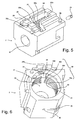
- the figure 5 represents an isometric view of the support 2.
- a housing 24 makes it possible to house the rotary roller.
- a first straight groove 25a and a second straight groove 25b serve as respective guides for the first shaft end 15a and the second shaft end 15b of the secondary shaft.
- An upper plate 26 receives the frame 6 allowing the final assembly of the secondary shaft and the elastic blades in the support.
- a circular hole 27 is intended to receive the first ring 8 of the rotary drum, so as to perform the bearing function.
- a recess 28 accommodates the first and second gears.
- a radial hole is provided to accommodate the pin serving as an orientation means 21.
- the support also comprises a cylindrical bore 33 comprising a helical groove 31, interrupted at the housing 24.
- the figure 6 represents an interior view of the support.
- the cylindrical bore 33 has a diameter greater than the diameter of the winding zone. Thus, the winding zone penetrates inside the support.
- a machining of the support or other technical means allows the realization of the helical groove, in which circulates the cord.
- This helical groove is delimited by a helical wall 30.
- Four sections 30a-30d of the helical wall appear at the housing 24, which interrupts the helical wall.
- the turns of the cord are no longer joined in this case.
- the helical wall thus serves as a second means of thrusting the turns towards the storage area in the case of a winding.
- the helical wall also serves as a means of thrusting the turns towards the guide means during unwinding.
- the helical groove has a depth greater than the radius of the cord.
- the interruption of the helical wall at the housing 24 can be only partial, the wall being continuous in its smallest diameter and only interrupted in its larger diameter so as to allow the pressing action of the rotary roller on the cord.
- the helical wall is preferably formed around the drum only at the level of the friction zone.
- the helical wall is only partially interrupted at the housing, and forms an integral piece integral inserted in the bore 33, for example by screwing.
- the zone 34 partially represents a tapping formed in the bore 33 of the support.
- the tapping may have the same pitch as the helical wall, and the latter (which comprises much fewer turns than the thread of the bearing and whose shape of the section is different from that of the thread of the tapping) is implemented by screwing in the thread.
- a helical wall termination is identified by reference 32. This termination is located beyond the friction zone. According to the invention, the helical wall may extend axially over the entire length of the winding zone, but it is preferable that it acts on at most one turn outside the friction zone. The termination is located, heading towards the storage area, within one turn of the last turn of the friction zone: for example three quarters of a turn on the figure 6 .
- the orientation means is itself located less than half a turn of the termination, so as to allow the cord orientation actions described above.
- This orientation means is therefore disposed within two turns of the last turn of the friction zone, preferably less than 1.5 turns.
- a notch 35 is formed allowing the first thrust means 13 to pass, as well as a hole 36 placed opposite the guiding means 12 and leaving the passage to the bead.
- the figure 7 represents in a partial view similar to that of the figure 4 an alternative embodiment of the cord input guiding means.
- the finger 13 completes the guide means 12 formed by the arrival hole of the cord in the base 5.
- the cord is guided by a central face 13b of the finger.
- the profile of this central face 13b is such that it provides a space between the winding drum and the central face 13b of width slightly greater than the diameter of the cord.
- the rounded profile of the central face of the finger facilitates the insertion movement of the cord on the winding drum and minimizes friction in the vicinity of the arrival hole of the cord.
- the central face of the finger can be shaped as a gutter.
- the central face 13b can be integrated into the support so that it understands itself this function of guiding the cord.
- the cord thus enters the reel in a plane perpendicular to the axis of rotation of the drum until reaching an upper end 13c of the finger 13. At this point, the cord penetrates into the helical groove, as indicated by a reference 22b .
- the cord winder comprises only one thrust means, namely the second thrust means.
- the behavior of the cord is such that it does not slip angularly on the winding drum in the winding zone, while it slides axially.
- the winding angle of the cord on the drum between the point of application of the rotary roller on the first turn of the cord and the first point of contact of the first turn to the drum is less than 180 ° in the case of the figure 4 , and preferably less than 60 °, typically 45 °, in the case of the figure 7 .
- the construction of the cord winder according to the invention therefore deviates from the devices of the prior art to have the considerable advantage of allowing the thrust of the cord outside the winder even in the absence of load on the cord, during an unwinding maneuver.
- the reels of the prior art generally have at most one turn wound on the winding drum, in a fully unwound position of the cord
- the winder according to the invention is such that the number of turns of the zone of friction is independent of the winding or unwinding state of the bead, which implies that in fully unrolled position there remains at least this minimum number of turns wound on the winding drum.
- the figure 4 22a represents the position of the cord in the storage zone, in a fully unwound position: the configuration of the cord between the guide means and the orientation means is, on the other hand, identical, that the winding drum is totally curled or fully unwound.
- the cord winder according to the invention also has the advantage of allowing a regular winding of the cord in the winder even in the absence of load on the cord. This feature is particularly useful in the case of window having a very low mass, or in the case where an involuntary movement of the user would relieve the load bar during a winding phase. It also makes it possible to reduce the mass of the load bar.
Description
L'invention concerne un enrouleur de cordon pour dispositif de couverture de fenêtre.The invention relates to a cord winder for a window covering device.
Un enrouleur de cordon équipe des dispositifs de protection solaire, d'occultation ou de décoration, disposés devant des baies vitrées et désignés par « dispositifs de couverture de fenêtre ». Ces dispositifs sont de type store vénitien, store bateau, store plissé, store bouillonné ou « Roman Shade ». Dans une configuration typique d'un tel dispositif, plusieurs enrouleurs à cordon sont disposés dans un caisson et peuvent être entraînés simultanément par un arbre d'entraînement commun, à l'aide d'un treuil manuel ou d'un moteur électrique. Les cordons sont attachés par une extrémité à une barre de charge tandis que le produit d'occultation, de décoration ou de protection solaire se déploie dans l'espace compris entre la barre de charge et le caisson. La surface visible du produit est proportionnelle au déroulement du cordon.A cord retractor is equipped with sun protection, concealment or decoration devices arranged in front of bay windows and designated as "window covering devices". These devices are venetian blind type, boat blind, pleated blind, bubble blind or "Roman Shade". In a typical configuration of such a device, several corded reels are arranged in a box and can be driven simultaneously by a common drive shaft, using a manual winch or an electric motor. The cords are attached at one end to a load bar while the occultation, decoration or sun protection product is deployed in the space between the load bar and the box. The visible surface of the product is proportional to the course of the cord.
L'art antérieur décrit de très nombreux modes de réalisation d'enrouleurs de cordon, destinés à ce type de dispositifs. Une véritable rupture dans ce domaine est l'introduction d'enrouleurs de cordon présentant fonctionnellement une zone d'enroulement du cordon, un moyen de poussée des spires enroulées vers une zone de stockage de spires enroulées, zone dans laquelle la tension des spires du cordon est devenue sensiblement nulle.The prior art describes very many embodiments of cord reels, intended for this type of device. A real breakthrough in this field is the introduction of cord reels having functionally a winding zone of the cord, a means of thrusting the turns wound to a wound coil storage area, zone in which the tension of the turns of the cord has become substantially zero.
Par effet physique dit « effet cabestan », la tension du cordon sur un tambour tend à décroître entre une spire nouvellement enroulée et une spire anciennement enroulée. Cependant, cet effet est insuffisant à permettre une poussée régulière de nombreuses spires sur un tambour d'enroulement purement cylindrique. Les spires primitivement enroulées ont tendance à se bloquer sur le tambour, et les nouvelles spires ne peuvent s'insérer en poussant celles-ci. Il y a alors chevauchement des spires. Pour éviter que se produise un tel chevauchement, il a été inventé d'accentuer l'effet cabestan en provoquant de plus une variation progressive ou brutale du diamètre du tambour d'enroulement.By physical effect called "capstan effect", the tension of the cord on a drum tends to decrease between a newly wound turn and a coil formerly wound. However, this effect is insufficient to allow a regular thrust of many turns on a purely cylindrical winding drum. The originally wound coils tend to hang on the drum, and new turns can not be inserted by pushing them. There is overlap of the turns. To prevent such an overlap from occurring, it has been invented to accentuate the capstan effect by further causing a gradual or abrupt variation in the diameter of the winding drum.
Le brevet
Le brevet
Les enrouleurs à cordon sont, pour la plupart, équipés d'un tambour d'enroulement à profil conique dans la zone d'enroulement.Cord reels are, for the most part, equipped with a conical profile winding drum in the winding area.
Cependant, il subsiste un problème lié principalement à la rencontre d'un obstacle par la barre de charge, lors d'une phase de déroulement du cordon. En effet, dans ce cas le cordon n'est plus tendu par le poids de la barre de charge. Si le mouvement de rotation du tambour se poursuit dans le sens du déroulement, le cordon a tendance à donner naissance à des spires lâches dont le diamètre va en croissant. Ces spires peuvent alors se chevaucher et s'emmêler. La situation ne s'améliore pas si l'obstacle disparaît brusquement : certains enrouleurs du dispositif peuvent reprendre une configuration normale alors que d'autres resteront dans une situation de coincement de spires, d'où une allure penchée de la barre de charge, qui ne pourra pas être compensée par un mouvement inverse de l'enroulement. Il y a de plus risque d'usure et de rupture du cordon.However, there remains a problem mainly related to the meeting of an obstacle by the load bar, during a phase of unfolding the cord. Indeed, in this case the cord is no longer tensioned by the weight of the load bar. If the rotational movement of the drum continues in the direction of unwinding, the cord tends to give rise to loose turns whose diameter is increasing. These turns can then overlap and become entangled. The situation does not improve if the obstacle disappears suddenly: some reels of the device can resume a normal configuration while others will remain in a situation of wedging turns, resulting in a leaning of the load bar, which can not be compensated by a reverse movement of the winding. There is also a risk of wear and breakage of the cord.
Le cas d'un obstacle est relativement rare, mais le même phénomène peut se produire à l'occasion d'un « point dur » dans une coulisse, par exemple lorsque le dispositif de couverture de fenêtre est guidé par des coulisses latérales.The case of an obstacle is relatively rare, but the same phenomenon can occur during a "hard point" in a slide, by example when the window covering device is guided by lateral slides.
Plusieurs documents de l'art antérieur tentent de remédier à ce genre de situation en ajoutant un couvercle au-dessus du tambour, de manière à laisser un espace limité entre le tambour et le couvercle. Ainsi vise-t-on à empêcher l'accroissement de diamètre des spires du cordon lors d'un déroulement, quand la charge appliquée au cordon n'est plus suffisante. Le brevet
Par ailleurs, le brevet
Ces solutions améliorent les conditions de déroulement du cordon mais ne peuvent suffire à contraindre le cordon à quitter l'enrouleur de cordon quand plus aucune tension n'est exercée sur celui-ci par la barre de charge. Il subsiste alors le problème mentionné ci-dessus, sous une forme plus ou moins grave.These solutions improve the unwinding conditions of the cord but can not be enough to force the cord to leave the cord winder when no more tension is exerted on it by the load bar. There then remains the problem mentioned above, in a more or less serious form.
Le problème se manifeste aussi occasionnellement lors d'une phase d'enroulement s'il arrive qu'un faux mouvement d'un occupant de la pièce vienne soulager le poids de la barre de charge : les dispositifs de l'art antérieur ne peuvent enrouler un cordon lorsqu'il n'est pas sous tension. Cette contrainte pousse souvent à alourdir la barre de charge et se traduit alors par une consommation inutile d'énergie ainsi que par la nécessité de surdimensionner un moteur d'entraînement.The problem also occurs occasionally during a winding phase if it happens that a false movement of an occupant of the room comes relieve the weight of the load bar: the devices of the prior art can not roll up a cord when it is not live. This constraint often pushes to increase the load bar and then results in unnecessary energy consumption and the need to oversize a drive motor.
Enfin, un tel faux mouvement sur la barre de charge peut également se produire en absence de manoeuvre d'enroulement ou de déroulement, et provoquer une remontée du cordon dans l'enrouleur et, par exemple, un chevauchement de spires. De tels faux mouvements peuvent se produire pendant les périodes de nettoyage des locaux ou des vitrages.Finally, such a false movement on the load bar can also occur in the absence of a winding or unwinding maneuver, and cause a rise of the cord in the reel and, for example, an overlap of turns. Such false movements can occur during cleaning periods of the premises or glazing.
Il existe pourtant un besoin d'enrouleurs de cordon présentant une fiabilité absolument totale. C'est notamment le cas pour des dispositifs de couverture de fenêtre disposés entre deux vitrages scellés, pour lesquels la moindre défaillance de l'enrouleur de cordon est interdite. Dans ce cas, les faux mouvements ne sont pas à craindre, mais les problèmes mentionnés plus haut peuvent simplement provenir de points durs apparaissant au fil de temps dans les coulisses de guidage du dispositif.There is however a need for cord reels with absolutely complete reliability. This is particularly the case for window covering devices arranged between two sealed windows, for which the slightest failure of the cord winder is prohibited. In this case, the false movements are not to be feared, but the problems mentioned above can simply come from hard points appearing over time in the guideways of the device.
Le but de l'invention est de fournir un enrouleur de cordon remédiant aux inconvénients ci-dessus et améliorant les enrouleurs de cordon connus de l'art antérieur. En particulier, l'invention permet d'améliorer l'enroulement et le déroulement d'un cordon de suspension de store en évitant tout risque d'emmêlement de celui-ci.The object of the invention is to provide a cord winder overcoming the above disadvantages and improving the cord reels known from the prior art. In particular, the invention improves the winding and unwinding of a blind suspension cord, avoiding any risk of entanglement thereof.
Selon l'invention, l'enrouleur de cordon d'un dispositif de couverture de fenêtre comprend un tambour d'enroulement d'un cordon apte à être entraîné en rotation autour d'un premier axe de révolution, un moyen de guidage du cordon vers le tambour d'enroulement, le tambour d'enroulement étant monté mobile en rotation dans un support., L'enrouleur comprend un galet rotatif monté sur le support selon un deuxième axe de révolution et comprend une zone de friction dans laquelle au moins une spire du cordon, enroulée sur le tambour d'enroulement, est en contact avec le galet rotatif.According to the invention, the cord winder of a window cover device comprises a winding drum of a cord adapted to be rotated about a first axis of revolution, a means of guiding the cord towards the winding drum, the winding drum being rotatably mounted in a support., The winder comprises a rotary roller mounted on the support according to a second axis of revolution and comprises a friction zone in which at least one turn the cord, wound on the winding drum, is in contact with the rotary roller.
La rotation du galet rotatif peut être asservie à la rotation du tambour d'enroulement par un moyen d'asservissement.The rotation of the rotary roller can be slaved to the rotation of the winding drum by a servo means.
Le moyen d'asservissement peut comprendre un premier pignon solidaire en rotation du tambour d'enroulement, et en prise avec un deuxième pignon solidaire en rotation du galet rotatif.The servo means may comprise a first pinion integral in rotation with the winding drum, and engaged with a second pinion integral in rotation with the rotary roller.
Dans la zone de friction, le galet rotatif peut appliquer une pression sur au moins une première spire du cordon enroulée sur le tambour d'enroulement, par exemple la première spire et une autre spire ou la première spire et deux autres spires.In the friction zone, the rotary roller may apply pressure to at least a first turn of the cord wound on the winding drum, for example the first turn and another turn or the first turn and two other turns.
L'enrouleur de cordon peut comprendre un moyen d'orientation du cordon, solidaire du support et disposé au voisinage de la zone de friction en s'éloignant du moyen de guidage et à moins de deux tours de cordon d'une dernière spire en contact avec le galet rotatif.The cord winder may comprise a means of orientation of the cord, secured to the support and disposed in the vicinity of the friction zone away from the guide means and less than two turns of cord a last turn in contact with the rotary roller.
Le nombre de spires de la zone de friction peut être indépendant de l'état d'enroulement ou de déroulement du cordon.The number of turns of the friction zone may be independent of the state of winding or unwinding of the bead.
Un moyen de poussée peut agir au moins sur les spires au contact du galet rotatif, pour les éloigner du moyen de guidage.A thrust means may act at least on the turns in contact with the rotary roller, away from the guide means.
Le moyen de poussée peut être une paroi hélicoïdale.The thrust means may be a helical wall.
La paroi hélicoïdale peut être ménagée dans un alésage cylindrique du support, ledit alésage cylindrique contenant au moins la zone de friction et la paroi hélicoïdale peut être au moins partiellement interrompue par un logement du galet rotatif.The helical wall may be formed in a cylindrical bore of the support, said cylindrical bore containing at least the friction zone and the helical wall may be at least partially interrupted by a housing of the rotary roller.
Le galet rotatif peut comprendre deux extrémités d'arbre, appartenant par exemple à un arbre secondaire, guidées dans le support, notamment par deux gorges droites ménagées dans le support.The rotary roller may comprise two shaft ends, belonging for example to a secondary shaft, guided in the support, in particular by two straight grooves formed in the support.
Un moyen de pression peut pousser le galet rotatif vers le tambour.Pressure means can push the rotating roller towards the drum.
Le moyen de pression peut comprendre un élément élastique du support en contact avec une extrémité d'arbre du galet rotatif.The pressure means may comprise an elastic member of the support in contact with a shaft end of the rotary roller.
Le galet rotatif peut comprendre un revêtement élastomère et/ou un revêtement de friction.The rotary roller may comprise an elastomeric coating and / or a friction coating.
Au plus cinq spires consécutives du cordon peuvent être en contact tangentiel avec le galet rotatif.At most five consecutive turns of the bead may be in tangential contact with the rotary roller.
Le cordon peut être guidé vers le tambour d'enroulement par une face centrale d'un doigt, engagé dans le support ou appartenant au support.The cord can be guided towards the winding drum by a central face of a finger, engaged in the support or belonging to the support.
L'invention sera mieux comprise à la lecture de la description qui va suivre, donnée uniquement à titre d'exemple et faite en se référant aux dessins annexés sur lesquels :
- La
figure 1 représente un mode de réalisation d'un enrouleur de cordon selon l'invention, en vue isométrique. - La
figure 2 représente une vue éclatée partielle et isométrique de ce mode de réalisation d'enrouleur à cordon. - La
figure 3 représente une vue assemblée des éléments de lafigure 2 . - La
figure 4 représente une vue de profil des éléments de lafigure 2 , avec assemblage partiel des éléments. - La
figure 5 représente une vue isométrique d'un palier du mode de réalisation d'enrouleur à cordon. - La
figure 6 représente une vue intérieure d'un palier. - La
figure 7 représente une variante de réalisation d'un moyen de guidage d'entrée du cordon utilisé dans le mode de réalisation d'enrouleur de cordon selon l'invention.
- The
figure 1 represents an embodiment of a cord winder according to the invention, in isometric view. - The
figure 2 is an exploded partial and isometric view of this cord winder embodiment. - The
figure 3 represents an assembled view of the elements of thefigure 2 . - The
figure 4 represents a profile view of the elements of thefigure 2 , with partial assembly of the elements. - The
figure 5 is an isometric view of a bearing of the cord winder embodiment. - The
figure 6 represents an interior view of a landing. - The
figure 7 represents an alternative embodiment of a cord input guiding means used in the cord winder embodiment of the invention.
L'invention améliore de manière très significative les enrouleurs de cordon pour couvertures de fenêtre de l'art antérieur par l'usage d'un galet rotatif disposé en contact direct avec les premières spires d'enroulement du cordon.The invention significantly improves the prior art window cover cord reels by the use of a rotary roller disposed in direct contact with the first winding turns of the cord.
La
Il comprend un support 2, formant un premier palier, et un deuxième palier 3 raccordé au support par un berceau 4. Le support est fixé sur un socle 5. Un cadre 6 est monté sur le support afin de permettre l'assemblage de plusieurs pièces sur le support. Un tambour d'enroulement 7 est supporté par le support et par le deuxième palier et est mobile en rotation autour d'un premier axe de rotation AA'. Alternativement, le support forme également le socle.It comprises a
La
Le tambour d'enroulement comprend une première bague 8 et une seconde bague 9, coaxiales avec le premier axe de rotation et engagées respectivement dans le premier palier et dans le deuxième palier. Ces bagues sont lisses extérieurement de manière à tourner dans les paliers, et sont évidées selon un alésage polygonal 10 apte à permettre l'engagement d'un arbre d'entraînement 20 pour transmettre un mouvement de rotation au tambour d'enroulement. L'arbre d'entraînement présente par exemple un profil hexagonal.The winding drum comprises a first ring 8 and a second ring 9, coaxial with the first axis of rotation and engaged respectively in the first bearing and in the second bearing. These rings are smooth externally so as to rotate in the bearings, and are recessed in a
Alternativement, les paliers ne sont pas nécessaires. Par exemple le deuxième palier n'est pas nécessaire, car le centrage du tambour d'enroulement sur le premier axe de rotation peut être assuré par l'arbre d'entraînement.Alternatively, the bearings are not necessary. For example the second bearing is not necessary because the centering of the winding drum on the first axis of rotation can be provided by the drive shaft.
De la même façon, le support peut ne pas former un premier palier quand le centrage du tambour d'enroulement sur le premier axe de rotation est assuré par l'arbre d'entraînement, pourvu que le support soit positionné avec précision par rapport au tambour d'enroulement.In the same way, the support may not form a first bearing when the centering of the winding drum on the first axis of rotation is ensured by the drive shaft, provided that the support is positioned accurately with respect to the drum winding.
Le tambour d'enroulement comprend un moyen d'accrochage 11 d'un cordon au tambour d'enroulement, par exemple sous forme d'un trou permettant le blocage d'un noeud réalisé sur le cordon une fois celui-ci engagé dans le trou. Alternativement, le moyen d'accrochage du cordon est mobile axialement le long du tambour d'enroulement, tout en étant bloqué en rotation par rapport à celui-ci.The winding drum comprises a
Un moyen de guidage 12 d'entrée du cordon dans l'enrouleur, par exemple un trou d'arrivée du cordon guidant le cordon vers le tambour d'enroulement, est disposé sur le socle 5, au voisinage d'un doigt 13. Le doigt 13 peut comprendre un premier moyen de poussée 13a du cordon, comme décrit plus loin. Alternativement, le premier moyen de poussée peut comprendre un épaulement, réalisé sur une extrémité du tambour d'enroulement.A guiding means 12 for entering the cord into the reel, for example an arrival hole of the cord guiding the cord towards the winding drum, is arranged on the
Le moyen de guidage peut comprendre une petite poulie ou alternativement deux rouleaux d'axes mobiles et sensiblement perpendiculaires, afin de guider l'entrée du cordon dans l'enrouleur de cordon tout en limitant les frottements.The guiding means may comprise a small pulley or alternatively two rollers of moving and substantially perpendicular axes, to guide the entry of the cord into the cord winder while limiting friction.
Un galet rotatif 14, mobile en rotation selon un deuxième axe de rotation B-B' sensiblement parallèle au premier axe de rotation, est disposé dans le support au voisinage du tambour d'enroulement, du moyen de guidage, et du premier moyen de poussée, comme précisé par la suite.A
Ce galet rotatif est monté par emmanchement sur un arbre secondaire 15, présentant une première extrémité d'arbre 15a et une seconde extrémité d'arbre 15b de l'arbre secondaire. Alternativement, le galet rotatif peut être prolongé par des pions axiaux formant la première extrémité d'arbre et la deuxième extrémité d'arbre. Le rôle du galet rotatif est d'appliquer une friction sur le cordon. Un moyen de pression 16, de préférence de type élastique, est tel que le galet rotatif applique une pression sur une ou plusieurs spires du cordon enroulé sur le tambour d'enroulement.This rotary roller is mounted by fitting on a
On entend par-là qu'une ou plusieurs spires du cordon sont à la fois en contact circonférentiel avec le tambour d'enroulement et en contact tangentiel avec le galet rotatif, le contact tangentiel étant de type pressant et entraînant une friction sur le cordon.By this is meant that one or more bead turns are both in circumferential contact with the winding drum and in tangential contact with the rotary roller, the tangential contact being of pressing type and causing friction on the bead.
Par exemple le moyen de pression exerce une poussée sur le galet rotatif de sorte qu'il soit rappelé vers le tambour d'enroulement en contact contre les spires enroulées du cordon. Ainsi, un premier élément élastique 16a (tel une lamelle en acier) et un deuxième élément élastique 16b viennent respectivement en appui élastique sur la première extrémité et la deuxième extrémité de l'arbre secondaire. Les deux éléments élastiques constituent le moyen de pression élastique 16 permettant au galet rotatif d'entraîner par friction des spires enroulées sur le tambour d'enroulement.For example, the pressure means exerts a thrust on the rotary roller so that it is returned to the winding drum in contact with the coiled turns of the cord. Thus, a first
Un premier pignon 17 est solidaire en rotation de l'arbre secondaire, tandis qu'un deuxième pignon 18 est solidaire en rotation du tambour d'enroulement. Le deuxième pignon est par exemple monté sur une portée du tambour munie d'un méplat 19, de préférence engagé en force sur la portée du tambour munie du méplat 19. Le premier pignon engrène dans le deuxième pignon. Le rôle des pignons est décrit plus bas.A
Un moyen d'orientation 21 du cordon est par exemple constitué par une goupille cylindrique dont l'axe du cylindre est orienté dans une direction au moins sensiblement radiale au tambour d'enroulement. Le moyen d'orientation est fixé sur le support. La distance radiale entre le moyen d'orientation et le tambour d'enroulement est très inférieure au diamètre du cordon. Ce moyen d'orientation peut être monté mobile en rotation autour de la direction radiale. Le rôle du moyen d'orientation est décrit plus bas.An orientation means 21 of the cord is for example constituted by a cylindrical pin whose axis of the cylinder is oriented in a direction at least substantially radial to the winding drum. The orientation means is fixed on the support. The radial distance between the orienting means and the winding drum is much smaller than the diameter of the bead. This orientation means can be rotatably mounted around the radial direction. The role of the orientation means is described below.
La
On désigne par « première spire » une première spire de cordon en contact avec le tambour d'enroulement lorsque l'on se déplace sur le cordon depuis le moyen de guidage 12 d'entrée du cordon dans l'enrouleur.The term "first turn" means a first bead turn in contact with the winding drum when moving on the bead from the guide means 12 to enter the cord into the winder.
Sur cette vue de profil, il apparaît nettement que le tambour d'enroulement comprend au moins :
- une première zone, dite zone d'enroulement 7a, située au voisinage du support, comprenant au moins la première spire et comprenant une zone de
friction 23 dans laquelle plusieurs spires du cordon sont en contact à la fois avec le tambour d'enroulement et avec le galet rotatif. Puis, en s'éloignant du support : - une deuxième zone,
dite zone intermédiaire 7b et/ou 7b', dans laquelle a lieu une diminution du diamètre du tambour d'enroulement. Puis, en s'éloignant du support : - une troisième zone, dite zone de stockage 7c, présentant un diamètre inférieur à celui de la zone d'enroulement, au moins au niveau de son raccordement avec la zone intermédiaire.
- a first zone, referred to as the winding zone 7a, situated in the vicinity of the support, comprising at least the first turn and comprising a
friction zone 23 in which several turns of the bead are in contact with both the winding drum and with the rotary roller. Then, moving away from the support: - a second zone, called
intermediate zone 7b and / or 7b ', in which there is a decrease in the diameter of the winding drum. Then, moving away from the support: - a third zone, called
storage zone 7c, having a diameter smaller than that of the winding zone, at least at its connection with the intermediate zone.
La zone d'enroulement 7a est donc une partie de tambour d'enroulement comprenant une première spire du cordon et comprenant la zone de friction 23 dans laquelle au moins une spire du cordon est à la fois en contact circonférentiel avec le tambour d'enroulement et en contact tangentiel avec le galet rotatif. La zone d'enroulement peut présenter une longueur axiale supérieure à l'extension axiale de la zone de friction, comme sur la
La zone d'enroulement présente préférentiellement un diamètre constant. Dans ce cas, l'arbre secondaire et le galet rotatif présentent un deuxième axe de rotation B-B' parallèle au premier axe de rotation A-A'. Alternativement, la zone d'enroulement peut présenter une décroissance régulière et faible du diamètre (quelques centièmes de millimètre par millimètre) quand on se rapproche de la zone intermédiaire. Cette géométrie légèrement conique peut être favorable à une opération de démoulage. Elle peut également permettre de favoriser l'effet cabestan.The winding zone preferably has a constant diameter. In this case, the secondary shaft and the rotary roller have a second axis of rotation B-B 'parallel to the first axis of rotation A-A'. Alternatively, the winding zone may have a regular and weak decrease in diameter (a few hundredths of a millimeter per millimeter) when approaching the intermediate zone. This slightly conical geometry may be favorable for a demolding operation. It can also help to promote the capstan effect.
Le tambour d'enroulement peut ne pas comprendre de discontinuité de forme, par exemple être formé d'une pièce de révolution conique, dont le diamètre décroît régulièrement quand on s'éloigne du moyen de guidage. Dans ce cas, la zone d'enroulement s'étend sur toute la longueur axiale du tambour d'enroulement.The winding drum may not include discontinuity of shape, for example be formed of a piece of conical revolution, whose diameter decreases regularly when moving away from the guide means. In this case, the winding zone extends over the entire axial length of the winding drum.
Dans le cas d'un profil conique de la zone d'enroulement, le deuxième axe de rotation est pris parallèle au côté du cône. Le deuxième axe de rotation reste donc sensiblement parallèle à une génératrice de la zone d'enroulement, cette génératrice pouvant être parallèle au premier axe de rotation (zone d'enroulement cylindrique) ou pouvant être légèrement inclinée par rapport à cet axe (zone d'enroulement conique).In the case of a conical profile of the winding area, the second axis of rotation is taken parallel to the side of the cone. The second axis of rotation therefore remains substantially parallel to a generatrix of the winding zone, this generatrix being able to be parallel to the first axis of rotation (cylindrical winding zone) or to be slightly inclined with respect to this axis (zone of rotation). conical winding).
Préférentiellement, le tambour d'enroulement est lisse, de manière à présenter un coefficient de frottement aussi faible que possible, notamment dans la direction axiale.Preferably, the winding drum is smooth, so as to have a coefficient of friction as low as possible, especially in the axial direction.
La friction du galet rotatif sur le cordon résulte de l'action du moyen de pression. Les lames élastiques exercent un effort sur l'arbre secondaire de manière à pousser le galet rotatif en direction du tambour d'enroulement et à frotter sur les spires situées dans la zone de friction. Alternativement, l'arbre secondaire est fixe, et le galet presseur comprend un revêtement élastiquement déformable apte à exercer une pression élastique sur le cordon et constituant alors le moyen de pression élastique.The friction of the rotary roller on the bead results from the action of the pressure means. The resilient blades exert a force on the secondary shaft so as to push the rotary roller toward the winding drum and to rub on the turns in the friction zone. Alternatively, the secondary shaft is fixed, and the pressure roller comprises an elastically deformable coating capable of exerting elastic pressure on the cord and then constituting the elastic pressure means.
Préférentiellement, il y a combinaison des lames élastiques et du revêtement élastiquement déformable, par exemple en élastomère, pour former le moyen de pression.Preferably, there is a combination of the elastic blades and the elastically deformable coating, for example elastomer, to form the pressure means.
Selon une variante de réalisation, la friction du galet rotatif sur le cordon résulte de l'action de la pesanteur, le galet rotatif étant alors réalisé dans un matériau de forte densité. Un revêtement de friction, ou un traitement de surface, peut aussi rendre suffisante la friction du galet sur le cordon, sans qu'il soit nécessaire d'utiliser un moyen de pression de type élastique. L'élasticité radiale du cordon peut également être mise à profit pour ne pas nécessiter un moyen de pression de type élastique.According to an alternative embodiment, the friction of the rotary roller on the bead results from the action of gravity, the rotary roller then being made of a material of high density. A friction coating, or a surface treatment, can also make sufficient friction of the roller on the cord, without the need to use an elastic-type pressure means. The radial elasticity of the cord can also be used to avoid the need for an elastic-type pressure means.
Le moyen d'orientation 21 est disposé sur le support, en sortie de la zone d'enroulement. Il permet de garantir une bonne sortie du cordon vers la zone de stockage dans le cas d'un enroulement, et inversement il permet de garantir une bonne entrée du cordon dans la zone d'enroulement dans le cas d'un déroulement.The orientation means 21 is arranged on the support, at the exit of the winding zone. It ensures a good exit of the cord to the storage area in the case of a winding, and conversely it ensures a good entry of the cord into the winding area in the case of unwinding.
Lors de son entrée dans l'enrouleur de cordon, le cordon subit une poussée axiale en direction de la zone de stockage par une surface latérale du doigt 13 constituant le premier moyen de poussée 13a. Ainsi, si les spires sont jointives, une nouvelle spire a tendance à pousser les spires déjà enroulées, en direction de la zone de stockage.Upon entering the cord winder, the cord is thrust axially towards the storage area by a side surface of the
Inversement, lors d'un déroulement, la friction du galet rotatif sur le cordon permet de pousser la dernière spire enroulée en direction du moyen de guidage 12, donc de pousser le cordon à sortir de l'enrouleur de cordon, ce qui résout le problème de l'art antérieur.Conversely, during unwinding, the friction of the rotary roller on the cord makes it possible to push the last coil wound towards the guide means 12, thus to push the cord out of the cord winder, which solves the problem. of the prior art.
Cependant, le fonctionnement est grandement amélioré par l'introduction d'un moyen d'asservissement de la rotation du galet rotatif à celle du tambour d'enroulement. Ce moyen d'asservissement comprend les premier et deuxième pignons déjà décrits. Si le rapport de démultiplication est sensiblement égal au rapport des diamètres respectifs du tambour d'enroulement et du galet rotatif, alors ces deux éléments présentent sensiblement une même vitesse tangentielle, vitesse qui est communiquée au cordon pour le faire sortir de l'enrouleur de cordon, ou le faire entrer dans l'enrouleur de cordon, même en absence de tension sur le cordon.However, the operation is greatly improved by the introduction of a means for controlling the rotation of the rotary roller to that of the winding drum. This servo means comprises the first and second gears already described. If the gear ratio is substantially equal to the ratio of the respective diameters of the winding drum and the rotary roller, then these two elements have substantially the same tangential speed, which speed is communicated to the cord to remove it from the cord winder , or get it into the cord winder, even in the absence of tension on the cord.
Dans le cas d'une zone d'enroulement où le diamètre du tambour évolue (zone conique), le galet peut aussi être conique de sorte que les vitesses tangentielles du tambour et du galet soient les mêmes en toute section transversale de la zone d'enroulement où se trouve le galet. Le deuxième axe de rotation est alors plus incliné que la génératrice de la zone d'enroulement, par rapport au premier axe de rotation.In the case of a winding zone where the diameter of the drum is changing (conical zone), the roller may also be conical so that the speeds tangential of the drum and the roller are the same in any cross section of the winding zone where the roller is located. The second axis of rotation is then more inclined than the generatrix of the winding zone, with respect to the first axis of rotation.
Le tambour d'enroulement est susceptible de prendre de nombreuses formes, pourvu qu'il comprenne une zone de friction telle que définie précédemment.The winding drum is capable of taking many forms, provided that it comprises a friction zone as defined above.
Par exemple, la zone de stockage 7c peut présenter un profil conique de diamètre légèrement croissant quand on s'éloigne du moyen de guidage. En effet, si le moyen d'accrochage du cordon est fixe, alors les spires voient leur diamètre croître quand elles sont poussées vers le moyen d'accrochage.For example, the
Par ailleurs, le fonctionnement est grandement amélioré par l'usage d'un deuxième moyen de poussée, décrit ci-après.Moreover, the operation is greatly improved by the use of a second thrust means, described below.
La
Sur la partie supérieure du support, un logement 24 permet de loger le galet rotatif. Une première gorge droite 25a et une deuxième gorge droite 25b servent de guidages respectifs pour la première extrémité d'arbre 15a et la deuxième extrémité d'arbre 15b de l'arbre secondaire. Un plat supérieur 26 reçoit le cadre 6 permettant l'assemblage final de l'arbre secondaire et des lames élastiques dans le support.On the upper part of the support, a
Un trou circulaire 27 est destiné à recevoir la première bague 8 du tambour rotatif, de manière à réaliser la fonction palier. Un évidement 28 permet de loger les premier et deuxième pignons. Un trou radial est ménagé pour accueillir la goupille servant de moyen d'orientation 21.A
Le support comprend également un alésage cylindrique 33 comprenant une gorge hélicoïdale 31, interrompue au niveau du logement 24.The support also comprises a
La
De plus, un usinage du support ou un autre moyen technique permet la réalisation de la gorge hélicoïdale, dans laquelle circule le cordon. Cette gorge hélicoïdale est délimitée par une paroi hélicoïdale 30. Quatre sections 30a-30d de la paroi hélicoïdale apparaissent au niveau du logement 24, qui interrompt la paroi hélicoïdale.In addition, a machining of the support or other technical means allows the realization of the helical groove, in which circulates the cord. This helical groove is delimited by a helical wall 30. Four
Apparaissent également en
Contrairement à l'art antérieur, les spires du cordon ne sont plus jointives dans ce cas. La paroi hélicoïdale sert donc de deuxième moyen de poussée des spires vers la zone de stockage dans le cas d'un enroulement.Unlike the prior art, the turns of the cord are no longer joined in this case. The helical wall thus serves as a second means of thrusting the turns towards the storage area in the case of a winding.
Inversement, la paroi hélicoïdale sert également de moyen de poussée des spires vers le moyen de guidage lors d'un déroulement.Conversely, the helical wall also serves as a means of thrusting the turns towards the guide means during unwinding.
La gorge hélicoïdale a une profondeur supérieure au rayon du cordon. L'interruption de la paroi hélicoïdale au niveau du logement 24 peut être seulement partielle, la paroi étant continue dans son plus petit diamètre et uniquement interrompue dans son plus grand diamètre de manière à permettre l'action de pression du galet rotatif sur le cordon.The helical groove has a depth greater than the radius of the cord. The interruption of the helical wall at the
La paroi hélicoïdale n'est de préférence ménagée autour du tambour qu'au niveau de la zone de friction.The helical wall is preferably formed around the drum only at the level of the friction zone.
Préférentiellement, la paroi hélicoïdale n'est que partiellement interrompue au niveau du logement, et forme une pièce monobloc indépendante, insérée dans l'alésage 33, par exemple par vissage. La zone 34 représente partiellement un taraudage ménagé dans l'alésage 33 du support. Le taraudage peut avoir le même pas que la paroi hélicoïdale, et celle-ci (qui comprend beaucoup moins de spires que le pas de vis du palier et dont la forme de la section est différente de celle du filet du taraudage) est mise en place par vissage dans le pas de vis.Preferably, the helical wall is only partially interrupted at the housing, and forms an integral piece integral inserted in the
Une terminaison de paroi hélicoïdale est repérée par la référence 32. Cette terminaison est située au-delà de la zone de friction. Selon l'invention, la paroi hélicoïdale peut s'étendre axialement sur toute la longueur de la zone d'enroulement, mais il est préférable qu'elle n'agisse sur au plus qu'une spire en dehors de la zone de friction. La terminaison est donc située, en se dirigeant vers la zone de stockage, à moins d'un tour de la dernière spire de la zone de friction : par exemple à trois quarts de tour sur la
Partant de cette terminaison, le moyen d'orientation est lui-même situé à moins d'un demi-tour de la terminaison, de manière à permettre les actions d'orientation du cordon décrites plus haut.From this termination, the orientation means is itself located less than half a turn of the termination, so as to allow the cord orientation actions described above.
Ce moyen d'orientation est donc disposé à moins de deux tours de la dernière spire de la zone de friction, préférentiellement à moins de 1.5 tour.This orientation means is therefore disposed within two turns of the last turn of the friction zone, preferably less than 1.5 turns.
Sur la
La
Dans cette variante préférée, le doigt 13 complète le moyen de guidage 12 formé par le trou d'arrivée du cordon dans le socle 5. Le cordon est guidé par une face centrale 13b du doigt. Le profil de cette face centrale 13b est tel qu'il ménage un espace entre le tambour d'enroulement et la face centrale 13b de largeur légèrement supérieure au diamètre du cordon. Ainsi, le profil arrondi de la face centrale du doigt facilite le mouvement d'introduction du cordon sur le tambour d'enroulement et minimise les frottements au voisinage du trou d'arrivée du cordon. Avantageusement, la face centrale du doigt peut être conformée en gouttière. Alternativement, la face centrale 13b peut être intégrée au support afin qu'il comprenne lui-même cette fonction de guidage du cordon.In this preferred embodiment, the
Le cordon pénètre donc dans l'enrouleur selon un plan perpendiculaire à l'axe de rotation du tambour jusqu'à atteindre une extrémité supérieure 13c du doigt 13. A ce niveau, le cordon pénètre dans la gorge hélicoïdale, comme repéré par une référence 22b.The cord thus enters the reel in a plane perpendicular to the axis of rotation of the drum until reaching an
Quand cette variante est utilisée, l'enrouleur de cordon ne comprend qu'un seul moyen de poussée, à savoir le deuxième moyen de poussée. Quel que soit le moyen de poussée utilisé, le comportement du cordon est tel qu'il ne glisse pas angulairement sur le tambour d'enroulement dans la zone d'enroulement, alors qu'il glisse axialement.When this variant is used, the cord winder comprises only one thrust means, namely the second thrust means. Whatever the means of thrust used, the behavior of the cord is such that it does not slip angularly on the winding drum in the winding zone, while it slides axially.
L'angle d'enroulement du cordon sur le tambour entre le point d'application du galet rotatif sur la première spire du cordon et le premier point de contact de la première spire au tambour est inférieur à 180° dans le cas de la
La construction de l'enrouleur de cordon selon l'invention s'écarte donc des dispositifs de l'art antérieur pour présenter l'avantage considérable de permettre la poussée du cordon en dehors de l'enrouleur même en absence de charge sur le cordon, lors d'une manoeuvre de déroulement. Alors que les enrouleurs de l'art antérieur présentent en général au plus une spire enroulée sur le tambour d'enroulement, dans une position totalement déroulée du cordon, l'enrouleur selon l'invention est tel que le nombre de spires de la zone de friction est indépendant de l'état d'enroulement ou de déroulement du cordon, ce qui implique qu'en position totalement déroulée il subsiste au moins ce nombre minimum de spires enroulées sur le tambour d'enroulement. La
De plus, l'enrouleur de cordon selon l'invention présente également l'avantage de permettre un enroulement régulier du cordon dans l'enrouleur même en absence de charge sur le cordon. Cette particularité est particulièrement utile dans le cas de dispositifs de couverture de fenêtre présentant une très faible masse, ou encore dans le cas où un mouvement involontaire de l'utilisateur viendrait soulager la barre de charge pendant une phase d'enroulement. Elle permet en outre de diminuer la masse de la barre de charge.In addition, the cord winder according to the invention also has the advantage of allowing a regular winding of the cord in the winder even in the absence of load on the cord. This feature is particularly useful in the case of window having a very low mass, or in the case where an involuntary movement of the user would relieve the load bar during a winding phase. It also makes it possible to reduce the mass of the load bar.
Claims (15)
- A cord winder (1) for a window covering device, comprising a drum (7) for winding a cord (40) adapted to be driven in rotation about a first revolution axis (A-A'), an element (12, 13b) for guiding the cord toward the winding drum, the winding drum being mounted to be mobile in rotation in a support (2), characterized in that it comprises a rotary roller (14) mounted on the support to rotate about a second revolution axis (B-B') and in that it comprises a friction area (23) in which at least one turn of the cord wound on the winding drum is in contact with the rotary roller.
- The cord winder claimed in claim 1, characterized in that the rotation of the rotary roller is slaved to the rotation of the winding drum by a slaving element (17, 18).
- A cord winder as claimed in either one of the preceding claims, characterized in that the slaving element comprise a first pinion (18) constrained to rotate with the winding drum and meshing with a second pinion (17) constrained to rotate with the rotary roller.
- A cord winder as claimed in any one of the preceding claims, characterized in that, in the friction area (23), the rotary roller applies pressure to at least a first turn of the cord wound onto the winding drum, for example the first turn and another turn or the first turn and two other turns.
- A cord winder as claimed in claim 4, characterized in that it comprises an element (21) for orienting the cord fastened to the support and disposed in the vicinity of the friction area in the direction away from the guide element and at least two turns of cord of a final turn in contact with the rotary roller.
- A cord winder as claimed in either one of claims 4 or 5, characterized in that the number of turns in the friction area is independent of the state of winding or of unwinding of the cord.
- A cord winder as claimed in any one of the preceding claims, characterized in that a pushing element (13a, 30) act at least on the turns in contact with the rotary roller to move them away from the guide element.
- A cord winder as claimed in claim 7, characterized in that the pushing element comprise a helical wall (30).
- A cord winder as claimed in claim 8, characterized in that the helical wall (30) is formed in a cylindrical bore (33) of the support, said cylindrical bore containing at least the friction area, and in that the helical wall is at least partially interrupted by a housing (24) of the rotary roller.
- A cord winder as claimed in any one of the preceding claims, characterized in that the rotary roller comprises two shaft ends (15a, 15b) belonging for example to a secondary shaft (15) and guided in the support, notably by two straight grooves (25a, 25b) provided in the support.
- A cord winder as claimed in any one of the preceding claims, characterized in that a pressing element (16) push the rotary roller toward the drum.
- A cord winder as claimed in claim 11, characterized in that the pressing element comprise an elastic element (16a, 16b) of the support in contact with a shaft end of the rotary roller.
- A cord winder according to any one of the preceding claims, characterized in that the rotary roller comprises an elastomer coating and/or a friction coating.
- A cord winder as claimed in any one of the preceding claims, characterized in that at most five consecutive turns of the cord are in tangential contact with the rotary roller.
- A cord winder as claimed in any one of the preceding claims, characterized in that the cord is guided toward the winding drum by a central face (13b) of a finger (13) engaged in the support or belonging to the support.
Applications Claiming Priority (2)
| Application Number | Priority Date | Filing Date | Title |
|---|---|---|---|
| FR1052075A FR2957966B1 (en) | 2010-03-23 | 2010-03-23 | CORD REEL OF A WINDOW COVER DEVICE |
| PCT/EP2011/054336 WO2011117232A1 (en) | 2010-03-23 | 2011-03-22 | Cord winder for a window-covering device |
Publications (2)
| Publication Number | Publication Date |
|---|---|
| EP2550421A1 EP2550421A1 (en) | 2013-01-30 |
| EP2550421B1 true EP2550421B1 (en) | 2014-05-07 |
Family
ID=42269541
Family Applications (1)
| Application Number | Title | Priority Date | Filing Date |
|---|---|---|---|
| EP11711307.6A Not-in-force EP2550421B1 (en) | 2010-03-23 | 2011-03-22 | Cord winder of a window shade |
Country Status (5)
| Country | Link |
|---|---|
| US (1) | US8777148B2 (en) |
| EP (1) | EP2550421B1 (en) |
| CN (1) | CN102884272B (en) |
| FR (1) | FR2957966B1 (en) |
| WO (1) | WO2011117232A1 (en) |
Families Citing this family (11)
| Publication number | Priority date | Publication date | Assignee | Title |
|---|---|---|---|---|
| FR3002968B1 (en) | 2013-03-05 | 2015-04-10 | Somfy Sas | ACTUATOR FOR DRIVING A STORE WITH STRAINABLE BLADES AND STORE COMPRISING SUCH ACTUATOR |
| CN103321559B (en) * | 2013-06-06 | 2015-08-05 | 杭州欧卡索拉科技有限公司 | The rope winding sorting mechanism of shutter lifting turner |
| CN103388445B (en) * | 2013-07-23 | 2015-05-20 | 杭州欧卡索拉科技有限公司 | Flat and round rope winding mechanism for variable pitch window shutter lifting overturning machine |
| CN104533269B (en) * | 2014-11-06 | 2017-02-01 | 杭州万事达装饰用品有限公司 | Single-rope shutters |
| CN209413813U (en) * | 2018-11-16 | 2019-09-20 | 雷振邦 | Louver driving device |
| US11434690B2 (en) * | 2019-05-08 | 2022-09-06 | Lutron Technology Company Llc | Lift cord spool for a motorized treatment |
| DE102019212097B4 (en) * | 2019-08-13 | 2021-05-27 | Bos Gmbh & Co. Kg | Cable drive system for a protective device of a vehicle interior |
| CN111232761B (en) * | 2020-03-18 | 2021-05-07 | 福建省宏港纺织科技有限公司 | Novel efficient winding device for warp knitting machine |
| USD970923S1 (en) * | 2020-04-15 | 2022-11-29 | Beijing Xiaomi Mobile Software Co., Ltd. | Curtain controller |
| USD963576S1 (en) * | 2020-04-15 | 2022-09-13 | Beijing Xiaomi Mobile Software Co., Ltd. | Motor for curtain controller |
| CN114249182A (en) * | 2020-09-22 | 2022-03-29 | 中国石油天然气股份有限公司 | Workover derrick guy rope tail rope processing device and processing method thereof |
Family Cites Families (15)
| Publication number | Priority date | Publication date | Assignee | Title |
|---|---|---|---|---|
| US3145939A (en) * | 1958-10-27 | 1964-08-25 | Mason | Spooling apparatus |
| DE4105298C2 (en) * | 1990-02-21 | 1996-04-11 | Bando Chemical Ind | Diving system for attaching adhesives or adhesives to ropes |
| US5228491A (en) * | 1992-04-03 | 1993-07-20 | General Clutch Corporation | Monocontrol venetian blind |
| FR2686934B1 (en) * | 1992-01-30 | 1994-04-15 | Somfy | DEVICE FOR WINDING STORE SUSPENSION CORD. |
| FR2728933A1 (en) * | 1995-01-04 | 1996-07-05 | Somfy | DEVICE FOR WINDING BLINDS OF SUSPENSION OF BLINDS |
| US5725040A (en) * | 1996-06-20 | 1998-03-10 | Harmonic Design, Inc. | Suspension cord winding device for window covering |
| US6536503B1 (en) * | 1999-03-23 | 2003-03-25 | Hunter Douglas Inc. | Modular transport system for coverings for architectural openings |
| US7441722B2 (en) * | 2001-09-18 | 2008-10-28 | Anthony J. Mancuso | Coil reel hold-down device |
| FR2833991B1 (en) * | 2001-12-21 | 2004-10-22 | Somfy | MOTORIZED CLOSURE OR SUN PROTECTION DEVICE |
| US7137430B2 (en) * | 2002-03-25 | 2006-11-21 | Rollease, Inc. | Mono control lift and tilt mechanism for horizontal blinds |
| ATE337464T1 (en) * | 2002-09-30 | 2006-09-15 | Toso Kk | HOISTING CABLE WINDING DEVICE FOR SOLAR ENERGY SHIELDING DEVICE |
| CN2594242Y (en) * | 2003-01-13 | 2003-12-24 | 王中航 | Hoist with automatic rope arrangement |
| US7159635B2 (en) * | 2003-06-25 | 2007-01-09 | Hunter Douglas Inc. | Lift cord spool for coverings for architectural openings |
| US7210646B2 (en) * | 2005-04-26 | 2007-05-01 | Hsu Mu-Chuan | Cord seat assembly |
| US7686059B2 (en) * | 2006-09-05 | 2010-03-30 | Hunter Douglas Inc. | Top down/bottom up control system for retractable shade |
-
2010
- 2010-03-23 FR FR1052075A patent/FR2957966B1/en not_active Expired - Fee Related
-
2011
- 2011-03-22 US US13/636,291 patent/US8777148B2/en not_active Expired - Fee Related
- 2011-03-22 WO PCT/EP2011/054336 patent/WO2011117232A1/en active Application Filing
- 2011-03-22 EP EP11711307.6A patent/EP2550421B1/en not_active Not-in-force
- 2011-03-22 CN CN201180022064.6A patent/CN102884272B/en not_active Expired - Fee Related
Also Published As
| Publication number | Publication date |
|---|---|
| WO2011117232A1 (en) | 2011-09-29 |
| FR2957966B1 (en) | 2012-04-13 |
| US20130001347A1 (en) | 2013-01-03 |
| US8777148B2 (en) | 2014-07-15 |
| CN102884272B (en) | 2015-05-13 |
| CN102884272A (en) | 2013-01-16 |
| FR2957966A1 (en) | 2011-09-30 |
| EP2550421A1 (en) | 2013-01-30 |
Similar Documents
| Publication | Publication Date | Title |
|---|---|---|
| EP2550421B1 (en) | Cord winder of a window shade | |
| EP0479719B1 (en) | Roll-up device with tubular motor for blinds or roller shutters or similar | |
| EP2122101B1 (en) | Device with a roller shutter | |
| CA2676738A1 (en) | Device with a shutter which may be wound on a drum | |
| FR2560922A1 (en) | Device preventing the application of excessive stress to the spring drive motor of a window blind | |
| EP0721048B1 (en) | Winding device for suspension cord of blinds | |
| EP1983143B1 (en) | Device for winding a suspension cord comprising means for guiding the cord | |
| FR2934307A1 (en) | Roller shutter installation for e.g. garage door, has telescopic device comprising translational locking unit formed of locking collar to lock rod in hollow sleeve, where collar is connected to sleeve according to degree of freedom | |
| EP3821104B1 (en) | Drive system driving a screen, and apparatus comprising such a system | |
| FR2955606A1 (en) | Slat blind operating device for window of professional or private dwelling, has driving unit for driving drum and pulley in rotation, and barrier that is arranged at level of groove to prevent loop out of groove during rotation of pulley | |
| EP0409786B1 (en) | Universal device for rolling up cords, cables and similar | |
| EP2076651A2 (en) | Suspension cord winding device for a shutter | |
| WO2020011841A1 (en) | Drive system driving a screen, and apparatus comprising such a system | |
| EP4039937A1 (en) | Device for winding a blind fabric | |
| EP0417270A1 (en) | Device for a roller-blind. | |
| EP1170459B1 (en) | Manual drive for roller blind | |
| FR2800121A1 (en) | Operating device for roller blind comprises wheel pair, reversible worm gear and braking system with clutch system to limit torque between shutter shaft and control | |
| FR3104633A1 (en) | Roll-up device for awning fabric | |
| EP1419100B1 (en) | Motor-driven winch | |
| BE1017125A6 (en) | Device roller curtain. | |
| WO2023280975A1 (en) | Method for adjusting a system having a motorised windable element and system having a motorised windable element implementing said method | |
| FR2967449A1 (en) | DEVICE FOR IMMOBILIZING A CLOSURE PLATE AND SOLAR CLOSURE OR PROTECTION PLANT COMPRISING SUCH A DEVICE | |
| FR2567604A1 (en) | Shackle-type device for handling | |
| FR3012508A1 (en) | VENETIAN STORE OPAQUE. | |
| FR2645202A1 (en) | Roller screen device |
Legal Events
| Date | Code | Title | Description |
|---|---|---|---|
| PUAI | Public reference made under article 153(3) epc to a published international application that has entered the european phase |
Free format text: ORIGINAL CODE: 0009012 |
|
| 17P | Request for examination filed |
Effective date: 20121008 |
|
| AK | Designated contracting states |
Kind code of ref document: A1 Designated state(s): AL AT BE BG CH CY CZ DE DK EE ES FI FR GB GR HR HU IE IS IT LI LT LU LV MC MK MT NL NO PL PT RO RS SE SI SK SM TR |
|
| DAX | Request for extension of the european patent (deleted) | ||
| GRAP | Despatch of communication of intention to grant a patent |
Free format text: ORIGINAL CODE: EPIDOSNIGR1 |
|
| INTG | Intention to grant announced |
Effective date: 20131011 |
|
| GRAS | Grant fee paid |
Free format text: ORIGINAL CODE: EPIDOSNIGR3 |
|
| GRAA | (expected) grant |
Free format text: ORIGINAL CODE: 0009210 |
|
| AK | Designated contracting states |
Kind code of ref document: B1 Designated state(s): AL AT BE BG CH CY CZ DE DK EE ES FI FR GB GR HR HU IE IS IT LI LT LU LV MC MK MT NL NO PL PT RO RS SE SI SK SM TR |
|
| REG | Reference to a national code |
Ref country code: GB Ref legal event code: FG4D Free format text: NOT ENGLISH |
|
| REG | Reference to a national code |
Ref country code: AT Ref legal event code: REF Ref document number: 666869 Country of ref document: AT Kind code of ref document: T Effective date: 20140515 |
|
| REG | Reference to a national code |
Ref country code: IE Ref legal event code: FG4D Free format text: LANGUAGE OF EP DOCUMENT: FRENCH |
|
| REG | Reference to a national code |
Ref country code: DE Ref legal event code: R096 Ref document number: 602011006807 Country of ref document: DE Effective date: 20140618 |
|
| REG | Reference to a national code |
Ref country code: SE Ref legal event code: TRGR |
|
| REG | Reference to a national code |
Ref country code: NL Ref legal event code: T3 |
|
| REG | Reference to a national code |
Ref country code: AT Ref legal event code: MK05 Ref document number: 666869 Country of ref document: AT Kind code of ref document: T Effective date: 20140507 |
|
| REG | Reference to a national code |
Ref country code: LT Ref legal event code: MG4D |
|
| PG25 | Lapsed in a contracting state [announced via postgrant information from national office to epo] |
Ref country code: GR Free format text: LAPSE BECAUSE OF FAILURE TO SUBMIT A TRANSLATION OF THE DESCRIPTION OR TO PAY THE FEE WITHIN THE PRESCRIBED TIME-LIMIT Effective date: 20140808 Ref country code: NO Free format text: LAPSE BECAUSE OF FAILURE TO SUBMIT A TRANSLATION OF THE DESCRIPTION OR TO PAY THE FEE WITHIN THE PRESCRIBED TIME-LIMIT Effective date: 20140807 Ref country code: LT Free format text: LAPSE BECAUSE OF FAILURE TO SUBMIT A TRANSLATION OF THE DESCRIPTION OR TO PAY THE FEE WITHIN THE PRESCRIBED TIME-LIMIT Effective date: 20140507 Ref country code: FI Free format text: LAPSE BECAUSE OF FAILURE TO SUBMIT A TRANSLATION OF THE DESCRIPTION OR TO PAY THE FEE WITHIN THE PRESCRIBED TIME-LIMIT Effective date: 20140507 Ref country code: IS Free format text: LAPSE BECAUSE OF FAILURE TO SUBMIT A TRANSLATION OF THE DESCRIPTION OR TO PAY THE FEE WITHIN THE PRESCRIBED TIME-LIMIT Effective date: 20140907 Ref country code: CY Free format text: LAPSE BECAUSE OF FAILURE TO SUBMIT A TRANSLATION OF THE DESCRIPTION OR TO PAY THE FEE WITHIN THE PRESCRIBED TIME-LIMIT Effective date: 20140507 |
|
| PG25 | Lapsed in a contracting state [announced via postgrant information from national office to epo] |
Ref country code: HR Free format text: LAPSE BECAUSE OF FAILURE TO SUBMIT A TRANSLATION OF THE DESCRIPTION OR TO PAY THE FEE WITHIN THE PRESCRIBED TIME-LIMIT Effective date: 20140507 Ref country code: LV Free format text: LAPSE BECAUSE OF FAILURE TO SUBMIT A TRANSLATION OF THE DESCRIPTION OR TO PAY THE FEE WITHIN THE PRESCRIBED TIME-LIMIT Effective date: 20140507 Ref country code: PL Free format text: LAPSE BECAUSE OF FAILURE TO SUBMIT A TRANSLATION OF THE DESCRIPTION OR TO PAY THE FEE WITHIN THE PRESCRIBED TIME-LIMIT Effective date: 20140507 Ref country code: RS Free format text: LAPSE BECAUSE OF FAILURE TO SUBMIT A TRANSLATION OF THE DESCRIPTION OR TO PAY THE FEE WITHIN THE PRESCRIBED TIME-LIMIT Effective date: 20140507 Ref country code: ES Free format text: LAPSE BECAUSE OF FAILURE TO SUBMIT A TRANSLATION OF THE DESCRIPTION OR TO PAY THE FEE WITHIN THE PRESCRIBED TIME-LIMIT Effective date: 20140507 Ref country code: AT Free format text: LAPSE BECAUSE OF FAILURE TO SUBMIT A TRANSLATION OF THE DESCRIPTION OR TO PAY THE FEE WITHIN THE PRESCRIBED TIME-LIMIT Effective date: 20140507 |
|
| PG25 | Lapsed in a contracting state [announced via postgrant information from national office to epo] |
Ref country code: PT Free format text: LAPSE BECAUSE OF FAILURE TO SUBMIT A TRANSLATION OF THE DESCRIPTION OR TO PAY THE FEE WITHIN THE PRESCRIBED TIME-LIMIT Effective date: 20140908 |
|
| PG25 | Lapsed in a contracting state [announced via postgrant information from national office to epo] |
Ref country code: CZ Free format text: LAPSE BECAUSE OF FAILURE TO SUBMIT A TRANSLATION OF THE DESCRIPTION OR TO PAY THE FEE WITHIN THE PRESCRIBED TIME-LIMIT Effective date: 20140507 Ref country code: RO Free format text: LAPSE BECAUSE OF FAILURE TO SUBMIT A TRANSLATION OF THE DESCRIPTION OR TO PAY THE FEE WITHIN THE PRESCRIBED TIME-LIMIT Effective date: 20140507 Ref country code: DK Free format text: LAPSE BECAUSE OF FAILURE TO SUBMIT A TRANSLATION OF THE DESCRIPTION OR TO PAY THE FEE WITHIN THE PRESCRIBED TIME-LIMIT Effective date: 20140507 Ref country code: EE Free format text: LAPSE BECAUSE OF FAILURE TO SUBMIT A TRANSLATION OF THE DESCRIPTION OR TO PAY THE FEE WITHIN THE PRESCRIBED TIME-LIMIT Effective date: 20140507 Ref country code: SK Free format text: LAPSE BECAUSE OF FAILURE TO SUBMIT A TRANSLATION OF THE DESCRIPTION OR TO PAY THE FEE WITHIN THE PRESCRIBED TIME-LIMIT Effective date: 20140507 |
|
| REG | Reference to a national code |
Ref country code: DE Ref legal event code: R097 Ref document number: 602011006807 Country of ref document: DE |
|
| PLBE | No opposition filed within time limit |
Free format text: ORIGINAL CODE: 0009261 |
|
| STAA | Information on the status of an ep patent application or granted ep patent |
Free format text: STATUS: NO OPPOSITION FILED WITHIN TIME LIMIT |
|
| PGFP | Annual fee paid to national office [announced via postgrant information from national office to epo] |
Ref country code: NL Payment date: 20150213 Year of fee payment: 5 |
|
| 26N | No opposition filed |
Effective date: 20150210 |
|
| PG25 | Lapsed in a contracting state [announced via postgrant information from national office to epo] |
Ref country code: IT Free format text: LAPSE BECAUSE OF FAILURE TO SUBMIT A TRANSLATION OF THE DESCRIPTION OR TO PAY THE FEE WITHIN THE PRESCRIBED TIME-LIMIT Effective date: 20140507 |
|
| REG | Reference to a national code |
Ref country code: DE Ref legal event code: R097 Ref document number: 602011006807 Country of ref document: DE Effective date: 20150210 |
|
| PGFP | Annual fee paid to national office [announced via postgrant information from national office to epo] |
Ref country code: GB Payment date: 20150316 Year of fee payment: 5 Ref country code: SE Payment date: 20150311 Year of fee payment: 5 |
|
| PG25 | Lapsed in a contracting state [announced via postgrant information from national office to epo] |
Ref country code: SI Free format text: LAPSE BECAUSE OF FAILURE TO SUBMIT A TRANSLATION OF THE DESCRIPTION OR TO PAY THE FEE WITHIN THE PRESCRIBED TIME-LIMIT Effective date: 20140507 |
|
| PG25 | Lapsed in a contracting state [announced via postgrant information from national office to epo] |
Ref country code: LU Free format text: LAPSE BECAUSE OF FAILURE TO SUBMIT A TRANSLATION OF THE DESCRIPTION OR TO PAY THE FEE WITHIN THE PRESCRIBED TIME-LIMIT Effective date: 20150322 Ref country code: MC Free format text: LAPSE BECAUSE OF FAILURE TO SUBMIT A TRANSLATION OF THE DESCRIPTION OR TO PAY THE FEE WITHIN THE PRESCRIBED TIME-LIMIT Effective date: 20140507 |
|
| REG | Reference to a national code |
Ref country code: CH Ref legal event code: PL |
|
| REG | Reference to a national code |
Ref country code: IE Ref legal event code: MM4A |
|
| PG25 | Lapsed in a contracting state [announced via postgrant information from national office to epo] |
Ref country code: LI Free format text: LAPSE BECAUSE OF NON-PAYMENT OF DUE FEES Effective date: 20150331 Ref country code: CH Free format text: LAPSE BECAUSE OF NON-PAYMENT OF DUE FEES Effective date: 20150331 Ref country code: IE Free format text: LAPSE BECAUSE OF NON-PAYMENT OF DUE FEES Effective date: 20150322 |
|
| REG | Reference to a national code |
Ref country code: FR Ref legal event code: PLFP Year of fee payment: 6 |
|
| REG | Reference to a national code |
Ref country code: SE Ref legal event code: EUG |
|
| REG | Reference to a national code |
Ref country code: NL Ref legal event code: MM Effective date: 20160401 |
|
| GBPC | Gb: european patent ceased through non-payment of renewal fee |
Effective date: 20160322 |
|
| PG25 | Lapsed in a contracting state [announced via postgrant information from national office to epo] |
Ref country code: SE Free format text: LAPSE BECAUSE OF NON-PAYMENT OF DUE FEES Effective date: 20160323 |
|
| PG25 | Lapsed in a contracting state [announced via postgrant information from national office to epo] |
Ref country code: MT Free format text: LAPSE BECAUSE OF FAILURE TO SUBMIT A TRANSLATION OF THE DESCRIPTION OR TO PAY THE FEE WITHIN THE PRESCRIBED TIME-LIMIT Effective date: 20140507 |
|
| PG25 | Lapsed in a contracting state [announced via postgrant information from national office to epo] |
Ref country code: GB Free format text: LAPSE BECAUSE OF NON-PAYMENT OF DUE FEES Effective date: 20160322 Ref country code: NL Free format text: LAPSE BECAUSE OF NON-PAYMENT OF DUE FEES Effective date: 20160401 |
|
| REG | Reference to a national code |
Ref country code: FR Ref legal event code: PLFP Year of fee payment: 7 |
|
| PG25 | Lapsed in a contracting state [announced via postgrant information from national office to epo] |
Ref country code: HU Free format text: LAPSE BECAUSE OF FAILURE TO SUBMIT A TRANSLATION OF THE DESCRIPTION OR TO PAY THE FEE WITHIN THE PRESCRIBED TIME-LIMIT; INVALID AB INITIO Effective date: 20110322 Ref country code: BG Free format text: LAPSE BECAUSE OF FAILURE TO SUBMIT A TRANSLATION OF THE DESCRIPTION OR TO PAY THE FEE WITHIN THE PRESCRIBED TIME-LIMIT Effective date: 20140507 Ref country code: SM Free format text: LAPSE BECAUSE OF FAILURE TO SUBMIT A TRANSLATION OF THE DESCRIPTION OR TO PAY THE FEE WITHIN THE PRESCRIBED TIME-LIMIT Effective date: 20140507 |
|
| PG25 | Lapsed in a contracting state [announced via postgrant information from national office to epo] |
Ref country code: BE Free format text: LAPSE BECAUSE OF NON-PAYMENT OF DUE FEES Effective date: 20150331 |
|
| PG25 | Lapsed in a contracting state [announced via postgrant information from national office to epo] |
Ref country code: TR Free format text: LAPSE BECAUSE OF FAILURE TO SUBMIT A TRANSLATION OF THE DESCRIPTION OR TO PAY THE FEE WITHIN THE PRESCRIBED TIME-LIMIT Effective date: 20140507 |
|
| REG | Reference to a national code |
Ref country code: FR Ref legal event code: PLFP Year of fee payment: 8 |
|
| PG25 | Lapsed in a contracting state [announced via postgrant information from national office to epo] |
Ref country code: MK Free format text: LAPSE BECAUSE OF FAILURE TO SUBMIT A TRANSLATION OF THE DESCRIPTION OR TO PAY THE FEE WITHIN THE PRESCRIBED TIME-LIMIT Effective date: 20140507 |
|
| PG25 | Lapsed in a contracting state [announced via postgrant information from national office to epo] |
Ref country code: AL Free format text: LAPSE BECAUSE OF FAILURE TO SUBMIT A TRANSLATION OF THE DESCRIPTION OR TO PAY THE FEE WITHIN THE PRESCRIBED TIME-LIMIT Effective date: 20140507 |
|
| PGFP | Annual fee paid to national office [announced via postgrant information from national office to epo] |
Ref country code: DE Payment date: 20190312 Year of fee payment: 9 Ref country code: FR Payment date: 20190313 Year of fee payment: 9 |
|
| REG | Reference to a national code |
Ref country code: DE Ref legal event code: R119 Ref document number: 602011006807 Country of ref document: DE |
|
| PG25 | Lapsed in a contracting state [announced via postgrant information from national office to epo] |
Ref country code: FR Free format text: LAPSE BECAUSE OF NON-PAYMENT OF DUE FEES Effective date: 20200331 Ref country code: DE Free format text: LAPSE BECAUSE OF NON-PAYMENT OF DUE FEES Effective date: 20201001 |