EP2550421B1 - Seilwickelvorrichtung eines fensterbehangs - Google Patents
Seilwickelvorrichtung eines fensterbehangs Download PDFInfo
- Publication number
- EP2550421B1 EP2550421B1 EP11711307.6A EP11711307A EP2550421B1 EP 2550421 B1 EP2550421 B1 EP 2550421B1 EP 11711307 A EP11711307 A EP 11711307A EP 2550421 B1 EP2550421 B1 EP 2550421B1
- Authority
- EP
- European Patent Office
- Prior art keywords
- cord
- rotary roller
- support
- winding drum
- winder
- Prior art date
- Legal status (The legal status is an assumption and is not a legal conclusion. Google has not performed a legal analysis and makes no representation as to the accuracy of the status listed.)
- Not-in-force
Links
Images


Classifications
-
- E—FIXED CONSTRUCTIONS
- E06—DOORS, WINDOWS, SHUTTERS, OR ROLLER BLINDS IN GENERAL; LADDERS
- E06B—FIXED OR MOVABLE CLOSURES FOR OPENINGS IN BUILDINGS, VEHICLES, FENCES OR LIKE ENCLOSURES IN GENERAL, e.g. DOORS, WINDOWS, BLINDS, GATES
- E06B9/00—Screening or protective devices for wall or similar openings, with or without operating or securing mechanisms; Closures of similar construction
- E06B9/24—Screens or other constructions affording protection against light, especially against sunshine; Similar screens for privacy or appearance; Slat blinds
- E06B9/26—Lamellar or like blinds, e.g. venetian blinds
- E06B9/28—Lamellar or like blinds, e.g. venetian blinds with horizontal lamellae, e.g. non-liftable
- E06B9/30—Lamellar or like blinds, e.g. venetian blinds with horizontal lamellae, e.g. non-liftable liftable
- E06B9/32—Operating, guiding, or securing devices therefor
- E06B9/322—Details of operating devices, e.g. pulleys, brakes, spring drums, drives
-
- E—FIXED CONSTRUCTIONS
- E06—DOORS, WINDOWS, SHUTTERS, OR ROLLER BLINDS IN GENERAL; LADDERS
- E06B—FIXED OR MOVABLE CLOSURES FOR OPENINGS IN BUILDINGS, VEHICLES, FENCES OR LIKE ENCLOSURES IN GENERAL, e.g. DOORS, WINDOWS, BLINDS, GATES
- E06B9/00—Screening or protective devices for wall or similar openings, with or without operating or securing mechanisms; Closures of similar construction
- E06B9/24—Screens or other constructions affording protection against light, especially against sunshine; Similar screens for privacy or appearance; Slat blinds
- E06B9/40—Roller blinds
- E06B9/42—Parts or details of roller blinds, e.g. suspension devices, blind boxes
-
- E—FIXED CONSTRUCTIONS
- E06—DOORS, WINDOWS, SHUTTERS, OR ROLLER BLINDS IN GENERAL; LADDERS
- E06B—FIXED OR MOVABLE CLOSURES FOR OPENINGS IN BUILDINGS, VEHICLES, FENCES OR LIKE ENCLOSURES IN GENERAL, e.g. DOORS, WINDOWS, BLINDS, GATES
- E06B9/00—Screening or protective devices for wall or similar openings, with or without operating or securing mechanisms; Closures of similar construction
- E06B9/24—Screens or other constructions affording protection against light, especially against sunshine; Similar screens for privacy or appearance; Slat blinds
- E06B9/26—Lamellar or like blinds, e.g. venetian blinds
- E06B9/28—Lamellar or like blinds, e.g. venetian blinds with horizontal lamellae, e.g. non-liftable
- E06B9/30—Lamellar or like blinds, e.g. venetian blinds with horizontal lamellae, e.g. non-liftable liftable
- E06B9/32—Operating, guiding, or securing devices therefor
- E06B9/322—Details of operating devices, e.g. pulleys, brakes, spring drums, drives
- E06B2009/3225—Arrangements to aid the winding of cords rollers
Definitions
- the invention relates to a cord winder for a window covering device.
- a cord retractor is equipped with sun protection, concealment or decoration devices arranged in front of bay windows and designated as "window covering devices". These devices are venetian blind type, boat blind, pleated blind, bubble blind or "Roman Shade”.
- sun covering devices are venetian blind type, boat blind, pleated blind, bubble blind or "Roman Shade”.
- several corded reels are arranged in a box and can be driven simultaneously by a common drive shaft, using a manual winch or an electric motor.
- the cords are attached at one end to a load bar while the occultation, decoration or sun protection product is deployed in the space between the load bar and the box.
- the visible surface of the product is proportional to the course of the cord.
- cord reels intended for this type of device.
- a real breakthrough in this field is the introduction of cord reels having functionally a winding zone of the cord, a means of thrusting the turns wound to a wound coil storage area, zone in which the tension of the turns of the cord has become substantially zero.
- capstan effect By physical effect called “capstan effect", the tension of the cord on a drum tends to decrease between a newly wound turn and a coil formerly wound. However, this effect is insufficient to allow a regular thrust of many turns on a purely cylindrical winding drum. The originally wound coils tend to hang on the drum, and new turns can not be inserted by pushing them. There is overlap of the turns. To prevent such an overlap from occurring, it has been invented to accentuate the capstan effect by further causing a gradual or abrupt variation in the diameter of the winding drum.
- Cord reels are, for the most part, equipped with a conical profile winding drum in the winding area.
- patent 7159635 also discloses a means for movably securing the cord along the winding drum, as also described in the patent US7,370,683 .
- Such a false movement on the load bar can also occur in the absence of a winding or unwinding maneuver, and cause a rise of the cord in the reel and, for example, an overlap of turns. Such false movements can occur during cleaning periods of the premises or glazing.
- cord reels with absolutely complete reliability. This is particularly the case for window covering devices arranged between two sealed windows, for which the slightest failure of the cord winder is prohibited. In this case, the false movements are not to be feared, but the problems mentioned above can simply come from hard points appearing over time in the guideways of the device.
- the object of the invention is to provide a cord winder overcoming the above disadvantages and improving the cord reels known from the prior art.
- the invention improves the winding and unwinding of a blind suspension cord, avoiding any risk of entanglement thereof.
- the cord winder of a window cover device comprises a winding drum of a cord adapted to be rotated about a first axis of revolution, a means of guiding the cord towards the winding drum, the winding drum being rotatably mounted in a support.
- the winder comprises a rotary roller mounted on the support according to a second axis of revolution and comprises a friction zone in which at least one turn the cord, wound on the winding drum, is in contact with the rotary roller.
- the rotation of the rotary roller can be slaved to the rotation of the winding drum by a servo means.
- the servo means may comprise a first pinion integral in rotation with the winding drum, and engaged with a second pinion integral in rotation with the rotary roller.
- the rotary roller may apply pressure to at least a first turn of the cord wound on the winding drum, for example the first turn and another turn or the first turn and two other turns.
- the cord winder may comprise a means of orientation of the cord, secured to the support and disposed in the vicinity of the friction zone away from the guide means and less than two turns of cord a last turn in contact with the rotary roller.
- the number of turns of the friction zone may be independent of the state of winding or unwinding of the bead.
- a thrust means may act at least on the turns in contact with the rotary roller, away from the guide means.
- the thrust means may be a helical wall.
- the helical wall may be formed in a cylindrical bore of the support, said cylindrical bore containing at least the friction zone and the helical wall may be at least partially interrupted by a housing of the rotary roller.
- the rotary roller may comprise two shaft ends, belonging for example to a secondary shaft, guided in the support, in particular by two straight grooves formed in the support.
- Pressure means can push the rotating roller towards the drum.
- the pressure means may comprise an elastic member of the support in contact with a shaft end of the rotary roller.
- the rotary roller may comprise an elastomeric coating and / or a friction coating.
- At most five consecutive turns of the bead may be in tangential contact with the rotary roller.
- the cord can be guided towards the winding drum by a central face of a finger, engaged in the support or belonging to the support.
- the invention significantly improves the prior art window cover cord reels by the use of a rotary roller disposed in direct contact with the first winding turns of the cord.
- the figure 1 represents a cord winder 1 according to the invention, in isometric view. As described in the prior art, the cord winder is intended to wind a cord 40 and to be arranged in a box of a cover device of a window, not shown.
- It comprises a support 2, forming a first bearing, and a second bearing 3 connected to the support by a cradle 4.
- the support is fixed on a base 5.
- a frame 6 is mounted on the support to allow the assembly of several parts on the support.
- a winding drum 7 is supported by the support and the second bearing and is rotatable about a first axis of rotation AA '.
- the support also forms the base.
- the figure 2 represents a partial exploded view and isometric view of the corded winder, and the figure 3 represents an assembled view of the elements of the figure 2 .
- the winding drum comprises a first ring 8 and a second ring 9, coaxial with the first axis of rotation and engaged respectively in the first bearing and in the second bearing.
- These rings are smooth externally so as to rotate in the bearings, and are recessed in a polygonal bore 10 adapted to allow the engagement of a drive shaft 20 to transmit a rotational movement to the winding drum.
- the drive shaft has for example a hexagonal profile.
- the bearings are not necessary.
- the second bearing is not necessary because the centering of the winding drum on the first axis of rotation can be provided by the drive shaft.
- the support may not form a first bearing when the centering of the winding drum on the first axis of rotation is ensured by the drive shaft, provided that the support is positioned accurately with respect to the drum winding.
- the winding drum comprises a means 11 for attaching a bead to the winding drum, for example in the form of a hole enabling the locking of a knot formed on the bead once it has engaged in the hole .
- the bead attachment means is axially movable along the winding drum, while being locked in rotation relative thereto.
- a guiding means 12 for entering the cord into the reel for example an arrival hole of the cord guiding the cord towards the winding drum, is arranged on the base 5, in the vicinity of a finger 13.
- the finger 13 may comprise a first thrust means 13a of the cord, as described below.
- the first thrust means may comprise a shoulder, made on one end of the winding drum.
- the guiding means may comprise a small pulley or alternatively two rollers of moving and substantially perpendicular axes, to guide the entry of the cord into the cord winder while limiting friction.
- a rotary roller 14, rotatable about a second axis of rotation BB 'substantially parallel to the first axis of rotation, is disposed in the support in the vicinity of the winding drum, the guide means, and the first thrust means, as specified later.
- This rotary roller is mounted by fitting on a secondary shaft 15, having a first shaft end 15a and a second shaft end 15b of the secondary shaft.
- the rotary roller may be extended by axial pins forming the first shaft end and the second shaft end.
- the role of the rotary roller is to apply friction on the cord.
- a pressure means 16, preferably of elastic type, is such that the rotary roller applies pressure to one or more turns of the cord wound on the winding drum.
- one or more bead turns are both in circumferential contact with the winding drum and in tangential contact with the rotary roller, the tangential contact being of pressing type and causing friction on the bead.
- the pressure means exerts a thrust on the rotary roller so that it is returned to the winding drum in contact with the coiled turns of the cord.
- a first elastic element 16a (such as a steel strip) and a second elastic element 16b respectively bear elastically on the first end and the second end of the secondary shaft.
- the two elastic elements constitute the elastic pressure means 16 allowing the rotary roller to frictionally drive turns wound on the winding drum.
- a first pinion 17 is integral in rotation with the secondary shaft, while a second pinion 18 is integral in rotation with the drum. winding.
- the second pinion is for example mounted on a drum surface provided with a flat 19, preferably engaged in force on the scope of the drum provided with the flat 19.
- the first pinion meshes with the second pinion. The role of the gears is described below.
- An orientation means 21 of the cord is for example constituted by a cylindrical pin whose axis of the cylinder is oriented in a direction at least substantially radial to the winding drum.
- the orientation means is fixed on the support.
- the radial distance between the orienting means and the winding drum is much smaller than the diameter of the bead.
- This orientation means can be rotatably mounted around the radial direction. The role of the orientation means is described below.
- the figure 4 represents a profile view of the elements of the figure 2 , with partial assembly of the elements and schematic representation of the cord 40 wound on several turns and a reference 22 diagrammatically dotted line a path in the winder.
- first turn means a first bead turn in contact with the winding drum when moving on the bead from the guide means 12 to enter the cord into the winder.
- the winding zone 7a is therefore a winding drum portion comprising a first turn of the bead and including the friction zone 23 in which at least one turn of the bead is both in circumferential contact with the winding drum and in tangential contact with the rotary roller.
- the winding zone may have an axial length greater than the axial extension of the friction zone, as on the figure 4 .
- the winding zone preferably has a constant diameter.
- the secondary shaft and the rotary roller have a second axis of rotation B-B 'parallel to the first axis of rotation A-A'.
- the winding zone may have a regular and weak decrease in diameter (a few hundredths of a millimeter per millimeter) when approaching the intermediate zone. This slightly conical geometry may be favorable for a demolding operation. It can also help to promote the capstan effect.
- the winding drum may not include discontinuity of shape, for example be formed of a piece of conical revolution, whose diameter decreases regularly when moving away from the guide means.
- the winding zone extends over the entire axial length of the winding drum.
- the second axis of rotation is taken parallel to the side of the cone.
- the second axis of rotation therefore remains substantially parallel to a generatrix of the winding zone, this generatrix being able to be parallel to the first axis of rotation (cylindrical winding zone) or to be slightly inclined with respect to this axis (zone of rotation). conical winding).
- the winding drum is smooth, so as to have a coefficient of friction as low as possible, especially in the axial direction.
- the friction of the rotary roller on the bead results from the action of the pressure means.
- the resilient blades exert a force on the secondary shaft so as to push the rotary roller toward the winding drum and to rub on the turns in the friction zone.
- the secondary shaft is fixed, and the pressure roller comprises an elastically deformable coating capable of exerting elastic pressure on the cord and then constituting the elastic pressure means.
- the elastic blades Preferably, there is a combination of the elastic blades and the elastically deformable coating, for example elastomer, to form the pressure means.
- the elastically deformable coating for example elastomer
- the friction of the rotary roller on the bead results from the action of gravity, the rotary roller then being made of a material of high density.
- a friction coating, or a surface treatment can also make sufficient friction of the roller on the cord, without the need to use an elastic-type pressure means.
- the radial elasticity of the cord can also be used to avoid the need for an elastic-type pressure means.
- the orientation means 21 is arranged on the support, at the exit of the winding zone. It ensures a good exit of the cord to the storage area in the case of a winding, and conversely it ensures a good entry of the cord into the winding area in the case of unwinding.
- the cord Upon entering the cord winder, the cord is thrust axially towards the storage area by a side surface of the finger 13 constituting the first thrust means 13a.
- a new turn tends to push the coils already wound in the direction of the storage area.
- This servo means comprises the first and second gears already described. If the gear ratio is substantially equal to the ratio of the respective diameters of the winding drum and the rotary roller, then these two elements have substantially the same tangential speed, which speed is communicated to the cord to remove it from the cord winder , or get it into the cord winder, even in the absence of tension on the cord.
- the roller may also be conical so that the speeds tangential of the drum and the roller are the same in any cross section of the winding zone where the roller is located.
- the second axis of rotation is then more inclined than the generatrix of the winding zone, with respect to the first axis of rotation.
- the winding drum is capable of taking many forms, provided that it comprises a friction zone as defined above.
- the storage area 7c may have a conical profile of slightly increasing diameter as one moves away from the guide means. Indeed, if the attachment means of the cord is fixed, then the turns see their diameter increase when they are pushed towards the attachment means.
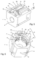
- the figure 5 represents an isometric view of the support 2.
- a housing 24 makes it possible to house the rotary roller.
- a first straight groove 25a and a second straight groove 25b serve as respective guides for the first shaft end 15a and the second shaft end 15b of the secondary shaft.
- An upper plate 26 receives the frame 6 allowing the final assembly of the secondary shaft and the elastic blades in the support.
- a circular hole 27 is intended to receive the first ring 8 of the rotary drum, so as to perform the bearing function.
- a recess 28 accommodates the first and second gears.
- a radial hole is provided to accommodate the pin serving as an orientation means 21.
- the support also comprises a cylindrical bore 33 comprising a helical groove 31, interrupted at the housing 24.
- the figure 6 represents an interior view of the support.
- the cylindrical bore 33 has a diameter greater than the diameter of the winding zone. Thus, the winding zone penetrates inside the support.
- a machining of the support or other technical means allows the realization of the helical groove, in which circulates the cord.
- This helical groove is delimited by a helical wall 30.
- Four sections 30a-30d of the helical wall appear at the housing 24, which interrupts the helical wall.
- the turns of the cord are no longer joined in this case.
- the helical wall thus serves as a second means of thrusting the turns towards the storage area in the case of a winding.
- the helical wall also serves as a means of thrusting the turns towards the guide means during unwinding.
- the helical groove has a depth greater than the radius of the cord.
- the interruption of the helical wall at the housing 24 can be only partial, the wall being continuous in its smallest diameter and only interrupted in its larger diameter so as to allow the pressing action of the rotary roller on the cord.
- the helical wall is preferably formed around the drum only at the level of the friction zone.
- the helical wall is only partially interrupted at the housing, and forms an integral piece integral inserted in the bore 33, for example by screwing.
- the zone 34 partially represents a tapping formed in the bore 33 of the support.
- the tapping may have the same pitch as the helical wall, and the latter (which comprises much fewer turns than the thread of the bearing and whose shape of the section is different from that of the thread of the tapping) is implemented by screwing in the thread.
- a helical wall termination is identified by reference 32. This termination is located beyond the friction zone. According to the invention, the helical wall may extend axially over the entire length of the winding zone, but it is preferable that it acts on at most one turn outside the friction zone. The termination is located, heading towards the storage area, within one turn of the last turn of the friction zone: for example three quarters of a turn on the figure 6 .
- the orientation means is itself located less than half a turn of the termination, so as to allow the cord orientation actions described above.
- This orientation means is therefore disposed within two turns of the last turn of the friction zone, preferably less than 1.5 turns.
- a notch 35 is formed allowing the first thrust means 13 to pass, as well as a hole 36 placed opposite the guiding means 12 and leaving the passage to the bead.
- the figure 7 represents in a partial view similar to that of the figure 4 an alternative embodiment of the cord input guiding means.
- the finger 13 completes the guide means 12 formed by the arrival hole of the cord in the base 5.
- the cord is guided by a central face 13b of the finger.
- the profile of this central face 13b is such that it provides a space between the winding drum and the central face 13b of width slightly greater than the diameter of the cord.
- the rounded profile of the central face of the finger facilitates the insertion movement of the cord on the winding drum and minimizes friction in the vicinity of the arrival hole of the cord.
- the central face of the finger can be shaped as a gutter.
- the central face 13b can be integrated into the support so that it understands itself this function of guiding the cord.
- the cord thus enters the reel in a plane perpendicular to the axis of rotation of the drum until reaching an upper end 13c of the finger 13. At this point, the cord penetrates into the helical groove, as indicated by a reference 22b .
- the cord winder comprises only one thrust means, namely the second thrust means.
- the behavior of the cord is such that it does not slip angularly on the winding drum in the winding zone, while it slides axially.
- the winding angle of the cord on the drum between the point of application of the rotary roller on the first turn of the cord and the first point of contact of the first turn to the drum is less than 180 ° in the case of the figure 4 , and preferably less than 60 °, typically 45 °, in the case of the figure 7 .
- the construction of the cord winder according to the invention therefore deviates from the devices of the prior art to have the considerable advantage of allowing the thrust of the cord outside the winder even in the absence of load on the cord, during an unwinding maneuver.
- the reels of the prior art generally have at most one turn wound on the winding drum, in a fully unwound position of the cord
- the winder according to the invention is such that the number of turns of the zone of friction is independent of the winding or unwinding state of the bead, which implies that in fully unrolled position there remains at least this minimum number of turns wound on the winding drum.
- the figure 4 22a represents the position of the cord in the storage zone, in a fully unwound position: the configuration of the cord between the guide means and the orientation means is, on the other hand, identical, that the winding drum is totally curled or fully unwound.
- the cord winder according to the invention also has the advantage of allowing a regular winding of the cord in the winder even in the absence of load on the cord. This feature is particularly useful in the case of window having a very low mass, or in the case where an involuntary movement of the user would relieve the load bar during a winding phase. It also makes it possible to reduce the mass of the load bar.
Landscapes
- Engineering & Computer Science (AREA)
- Structural Engineering (AREA)
- Architecture (AREA)
- Civil Engineering (AREA)
- Storing, Repeated Paying-Out, And Re-Storing Of Elongated Articles (AREA)
- Operating, Guiding And Securing Of Roll- Type Closing Members (AREA)
Claims (15)
- Seilwickelvorrichtung (1) eines Fensterbehangs, die eine Wickeltrommel (7) eines Seils (40), die geeignet ist, um eine erste Umdrehungsachse (A - A') drehangetrieben zu werden, und ein Mittel (12, 13b) zum Führen des Seils zur Wickeltrommel umfasst, wobei die Wickeltrommel drehbeweglich in einer Stütze (2) montiert ist, dadurch gekennzeichnet, dass sie eine Rotationsrolle (14) umfasst, die gemäß einer zweiten Umdrehungsachse (B - B') an der Stütze montiert ist, und dass sie einen Reibungsbereich (23) umfasst, in dem mindestens eine auf die Wickeltrommel aufgewickelte Seillage des Seils mit der Rotationsrolle in Kontakt ist.
- Seilwickelvorrichtung nach Anspruch 1, dadurch gekennzeichnet, dass die Drehung der Rotationsrolle durch ein Servomittel (17, 18) der Drehung der Wickeltrommel nachgeführt wird.
- Seilwickelvorrichtung nach einem der vorhergehenden Ansprüche, dadurch gekennzeichnet, dass das Servomittel ein erstes Ritzel (18) umfasst, das drehfest mit der Wickeltrommel verbunden ist und mit einem zweiten Ritzel (17) in Eingriff steht, das drehfest mit der Rotationsrolle verbunden ist.
- Seilwickelvorrichtung nach einem der vorhergehenden Ansprüche, dadurch gekennzeichnet, dass die Rotationsrolle im Reibungsbereich (23) auf mindestens eine erste auf die Wickeltrommel aufgewickelte Seillage des Seils, beispielsweise die erste Seillage und eine andere Seillage oder die erste Seillage und zwei andere Seillagen, einen Druck ausübt.
- Seilwickelvorrichtung nach Anspruch 4, dadurch gekennzeichnet, dass sie ein Mittel (21) zur Ausrichtung des Seils umfasst, das fest mit der Stütze verbunden ist und in der Nähe des Reibungsbereichs in Richtung weg vom Führungsmittel und an weniger als zwei Seilwindungen einer letzten Seillage in Kontakt mit der Rotationsrolle angeordnet ist.
- Seilwickelvorrichtung nach Anspruch 4 oder 5, dadurch gekennzeichnet, dass die Anzahl von Seillagen des Reibungsbereichs vom Auf- oder Abwickelzustand des Seils unabhängig ist.
- Seilwickelvorrichtung nach einem der vorhergehenden Ansprüche, dadurch gekennzeichnet, dass ein Schiebemittel (13a, 30) mindestens auf die Seillagen in Kontakt mit der Rotationsrolle wirkt, um sie vom Führungsmittel zu entfernen.
- Seilwickelvorrichtung nach Anspruch 7, dadurch gekennzeichnet, dass das Schiebemittel eine schraubenförmige Wand (30) ist.
- Seilwickelvorrichtung nach Anspruch 8, dadurch gekennzeichnet, dass die schraubenförmige Wand (30) in einer zylindrischen Bohrung (33) der Stütze ausgeführt ist und mindestens den Reibungsbereich enthält und dass die schraubenförmige Wand mindestens teilweise durch eine Aufnahme (24) der Rotationsrolle unterbrochen ist.
- Seilwickelvorrichtung nach einem der vorhergehenden Ansprüche, dadurch gekennzeichnet, dass die Rotationsrolle zwei Wellenenden (15a, 15b) umfasst, die beispielsweise zu einer Nebenwelle (15) gehören und besonders durch zwei in der Stütze ausgeführte gerade Nuten (25a, 25b) in der Stütze geführt sind.
- Seilwickelvorrichtung nach einem der vorhergehenden Ansprüche, dadurch gekennzeichnet, dass ein Drückmittel (16) die Rotationsrolle zur Trommel hin drückt.
- Seilwickelvorrichtung nach Anspruch 11, dadurch gekennzeichnet, dass das Drückmittel ein elastisches Element (16a, 16b) der Stütze in Kontakt mit einem Wellenende der Rotationsrolle umfasst.
- Seilwickelvorrichtung nach einem der vorhergehenden Ansprüche, dadurch gekennzeichnet, dass die Rotationsrolle einen Elastomerbelag und/oder Reibbelag umfasst.
- Seilwickelvorrichtung nach einem der vorhergehenden Ansprüche, dadurch gekennzeichnet, dass höchstens fünf aufeinanderfolgende Seillagen des Seils in tangentialem Kontakt mit der Rotationsrolle sind.
- Seilwickelvorrichtung nach einem der vorhergehenden Ansprüche, dadurch gekennzeichnet, dass das Seil durch eine zentrale Fläche (13b) eines Fingers (13) zur Wickeltrommel hin geführt wird, der mit der Stütze in Eingriff steht oder zur Stütze gehört.
Applications Claiming Priority (2)
| Application Number | Priority Date | Filing Date | Title |
|---|---|---|---|
| FR1052075A FR2957966B1 (fr) | 2010-03-23 | 2010-03-23 | Enrouleur de cordon d'un dispositif de couverture de fenetre |
| PCT/EP2011/054336 WO2011117232A1 (fr) | 2010-03-23 | 2011-03-22 | Enrouleur de cordon d'un dispositif de couverture de fenetre |
Publications (2)
| Publication Number | Publication Date |
|---|---|
| EP2550421A1 EP2550421A1 (de) | 2013-01-30 |
| EP2550421B1 true EP2550421B1 (de) | 2014-05-07 |
Family
ID=42269541
Family Applications (1)
| Application Number | Title | Priority Date | Filing Date |
|---|---|---|---|
| EP11711307.6A Not-in-force EP2550421B1 (de) | 2010-03-23 | 2011-03-22 | Seilwickelvorrichtung eines fensterbehangs |
Country Status (5)
| Country | Link |
|---|---|
| US (1) | US8777148B2 (de) |
| EP (1) | EP2550421B1 (de) |
| CN (1) | CN102884272B (de) |
| FR (1) | FR2957966B1 (de) |
| WO (1) | WO2011117232A1 (de) |
Families Citing this family (11)
| Publication number | Priority date | Publication date | Assignee | Title |
|---|---|---|---|---|
| FR3002968B1 (fr) | 2013-03-05 | 2015-04-10 | Somfy Sas | Actionneur d'entrainement d'un store a lames orientables et store comprenant un tel actionneur |
| CN103321559B (zh) * | 2013-06-06 | 2015-08-05 | 杭州欧卡索拉科技有限公司 | 百叶窗升降翻转器的绳索卷绕排序机构 |
| CN103388445B (zh) * | 2013-07-23 | 2015-05-20 | 杭州欧卡索拉科技有限公司 | 一种适用于扁绳与圆绳的变节距百叶窗升降翻转器的卷绳机构 |
| CN104533269B (zh) * | 2014-11-06 | 2017-02-01 | 杭州万事达装饰用品有限公司 | 一种单绳卷帘 |
| CN209413813U (zh) * | 2018-11-16 | 2019-09-20 | 雷振邦 | 百叶窗驱动装置 |
| US11434690B2 (en) * | 2019-05-08 | 2022-09-06 | Lutron Technology Company Llc | Lift cord spool for a motorized treatment |
| DE102019212097B4 (de) * | 2019-08-13 | 2021-05-27 | Bos Gmbh & Co. Kg | Seilantriebssystem für eine Schutzvorrichtung eines Fahrzeuginnenraums |
| CN111232761B (zh) * | 2020-03-18 | 2021-05-07 | 福建省宏港纺织科技有限公司 | 一种经编机用新型高效的绕线装置 |
| USD970923S1 (en) * | 2020-04-15 | 2022-11-29 | Beijing Xiaomi Mobile Software Co., Ltd. | Curtain controller |
| USD963576S1 (en) * | 2020-04-15 | 2022-09-13 | Beijing Xiaomi Mobile Software Co., Ltd. | Motor for curtain controller |
| CN114249182B (zh) * | 2020-09-22 | 2024-05-28 | 中国石油天然气股份有限公司 | 一种修井作业井架绷绳尾绳处理装置及其处理方法 |
Family Cites Families (15)
| Publication number | Priority date | Publication date | Assignee | Title |
|---|---|---|---|---|
| US3145939A (en) * | 1958-10-27 | 1964-08-25 | Mason | Spooling apparatus |
| DE4105298C2 (de) * | 1990-02-21 | 1996-04-11 | Bando Chemical Ind | Tauchanlage zur Anbringung von Klebe- oder Haftmitteln an Seilen |
| US5228491A (en) * | 1992-04-03 | 1993-07-20 | General Clutch Corporation | Monocontrol venetian blind |
| FR2686934B1 (fr) * | 1992-01-30 | 1994-04-15 | Somfy | Dispositif d'enroulement de cordon de suspension de store. |
| FR2728933A1 (fr) * | 1995-01-04 | 1996-07-05 | Somfy | Dispositif d'enroulement de cordon de suspension de stores |
| US5725040A (en) * | 1996-06-20 | 1998-03-10 | Harmonic Design, Inc. | Suspension cord winding device for window covering |
| US6536503B1 (en) * | 1999-03-23 | 2003-03-25 | Hunter Douglas Inc. | Modular transport system for coverings for architectural openings |
| US7441722B2 (en) * | 2001-09-18 | 2008-10-28 | Anthony J. Mancuso | Coil reel hold-down device |
| FR2833991B1 (fr) * | 2001-12-21 | 2004-10-22 | Somfy | Dispositif de fermeture ou de protection solaire motorise |
| US7137430B2 (en) * | 2002-03-25 | 2006-11-21 | Rollease, Inc. | Mono control lift and tilt mechanism for horizontal blinds |
| KR100746861B1 (ko) * | 2002-09-30 | 2007-08-07 | 도소 가부시키가이샤 | 일사차폐장치의 승강코드 권취기구 |
| CN2594242Y (zh) * | 2003-01-13 | 2003-12-24 | 王中航 | 自动排绳卷扬机 |
| US7159635B2 (en) * | 2003-06-25 | 2007-01-09 | Hunter Douglas Inc. | Lift cord spool for coverings for architectural openings |
| US7210646B2 (en) * | 2005-04-26 | 2007-05-01 | Hsu Mu-Chuan | Cord seat assembly |
| US7686059B2 (en) * | 2006-09-05 | 2010-03-30 | Hunter Douglas Inc. | Top down/bottom up control system for retractable shade |
-
2010
- 2010-03-23 FR FR1052075A patent/FR2957966B1/fr not_active Expired - Fee Related
-
2011
- 2011-03-22 US US13/636,291 patent/US8777148B2/en not_active Expired - Fee Related
- 2011-03-22 EP EP11711307.6A patent/EP2550421B1/de not_active Not-in-force
- 2011-03-22 CN CN201180022064.6A patent/CN102884272B/zh not_active Expired - Fee Related
- 2011-03-22 WO PCT/EP2011/054336 patent/WO2011117232A1/fr active Application Filing
Also Published As
| Publication number | Publication date |
|---|---|
| CN102884272A (zh) | 2013-01-16 |
| WO2011117232A1 (fr) | 2011-09-29 |
| FR2957966B1 (fr) | 2012-04-13 |
| EP2550421A1 (de) | 2013-01-30 |
| FR2957966A1 (fr) | 2011-09-30 |
| US8777148B2 (en) | 2014-07-15 |
| US20130001347A1 (en) | 2013-01-03 |
| CN102884272B (zh) | 2015-05-13 |
Similar Documents
| Publication | Publication Date | Title |
|---|---|---|
| EP2550421B1 (de) | Seilwickelvorrichtung eines fensterbehangs | |
| EP0479719B1 (de) | Aufrolleinrichtung mit rohrförmigem Motor für Stores, Jalousien oder dergleichen | |
| EP2122101B1 (de) | Vorrichtung mit aufwickelbarem vorhang | |
| CA2676738A1 (fr) | Dispositif a volet enroulable autour d'un tambour | |
| FR2560922A1 (fr) | Dispositif pour empecher l'application d'une tension excessive au moteur a ressort d'un store de fenetre | |
| EP0721048B1 (de) | Wickelvorrichtung für Tragebänder von Jalousien | |
| EP1983143B1 (de) | Aufrollvorrichtung für eine Tragschnur mit einer Führung für die Schnur | |
| FR2934307A1 (fr) | Installation de volet roulant a axe d'enroulement du tablier telescopique | |
| EP3821104B1 (de) | Antriebssystem zum antreiben eines bildschirms und vorrichtung mit einem solchen system | |
| FR2955606A1 (fr) | Dispositif pour manoeuvrer un store a lames. | |
| EP0409786B1 (de) | Universale Vorrichtung zum Aufrollen von Schnüren, Kabeln und anderen | |
| EP2076651A2 (de) | Tragebandwickelvorrichtung für einen roll-laden | |
| EP3821103A1 (de) | Ansteuerungssystem zur ansteuerung eines bildschirms und vorrichtung mit solch einem system | |
| EP4039937A1 (de) | Vorrichtung zum aufrollen eines markisentuchs | |
| EP0417270A1 (de) | Schirmwickelvorrichtung. | |
| EP1170459B1 (de) | Handantrieb für Rollladen | |
| FR2800121A1 (fr) | Dispositif de manoeuvre pour volet roulant, store et similaire, a commande par manivelle comportant un systeme limiteur de couple | |
| FR3104633A1 (fr) | Dispositif d'enroulement d'une toile de store | |
| EP1419100B1 (de) | Motorangetriebene winde | |
| BE1017125A6 (fr) | Dispositif a rideau enroulable. | |
| WO2023280975A1 (fr) | Procede de reglage d'une installation d'element enroulable motorise et installation d'element enroulable motorise mettant en oeuvre ledit procede | |
| FR2967449A1 (fr) | Dispositif d'immobilisation d'une plaque de fermeture et installation de fermeture ou de protection solaire comprenant un tel dispositif | |
| FR2567604A1 (fr) | Dispositif du genre manille pour la manutention | |
| FR3012508A1 (fr) | Store venitien opaque. | |
| FR2645202A1 (fr) | Dispositif d'ecran a enroulement |
Legal Events
| Date | Code | Title | Description |
|---|---|---|---|
| PUAI | Public reference made under article 153(3) epc to a published international application that has entered the european phase |
Free format text: ORIGINAL CODE: 0009012 |
|
| 17P | Request for examination filed |
Effective date: 20121008 |
|
| AK | Designated contracting states |
Kind code of ref document: A1 Designated state(s): AL AT BE BG CH CY CZ DE DK EE ES FI FR GB GR HR HU IE IS IT LI LT LU LV MC MK MT NL NO PL PT RO RS SE SI SK SM TR |
|
| DAX | Request for extension of the european patent (deleted) | ||
| GRAP | Despatch of communication of intention to grant a patent |
Free format text: ORIGINAL CODE: EPIDOSNIGR1 |
|
| INTG | Intention to grant announced |
Effective date: 20131011 |
|
| GRAS | Grant fee paid |
Free format text: ORIGINAL CODE: EPIDOSNIGR3 |
|
| GRAA | (expected) grant |
Free format text: ORIGINAL CODE: 0009210 |
|
| AK | Designated contracting states |
Kind code of ref document: B1 Designated state(s): AL AT BE BG CH CY CZ DE DK EE ES FI FR GB GR HR HU IE IS IT LI LT LU LV MC MK MT NL NO PL PT RO RS SE SI SK SM TR |
|
| REG | Reference to a national code |
Ref country code: GB Ref legal event code: FG4D Free format text: NOT ENGLISH |
|
| REG | Reference to a national code |
Ref country code: AT Ref legal event code: REF Ref document number: 666869 Country of ref document: AT Kind code of ref document: T Effective date: 20140515 |
|
| REG | Reference to a national code |
Ref country code: IE Ref legal event code: FG4D Free format text: LANGUAGE OF EP DOCUMENT: FRENCH |
|
| REG | Reference to a national code |
Ref country code: DE Ref legal event code: R096 Ref document number: 602011006807 Country of ref document: DE Effective date: 20140618 |
|
| REG | Reference to a national code |
Ref country code: SE Ref legal event code: TRGR |
|
| REG | Reference to a national code |
Ref country code: NL Ref legal event code: T3 |
|
| REG | Reference to a national code |
Ref country code: AT Ref legal event code: MK05 Ref document number: 666869 Country of ref document: AT Kind code of ref document: T Effective date: 20140507 |
|
| REG | Reference to a national code |
Ref country code: LT Ref legal event code: MG4D |
|
| PG25 | Lapsed in a contracting state [announced via postgrant information from national office to epo] |
Ref country code: GR Free format text: LAPSE BECAUSE OF FAILURE TO SUBMIT A TRANSLATION OF THE DESCRIPTION OR TO PAY THE FEE WITHIN THE PRESCRIBED TIME-LIMIT Effective date: 20140808 Ref country code: NO Free format text: LAPSE BECAUSE OF FAILURE TO SUBMIT A TRANSLATION OF THE DESCRIPTION OR TO PAY THE FEE WITHIN THE PRESCRIBED TIME-LIMIT Effective date: 20140807 Ref country code: LT Free format text: LAPSE BECAUSE OF FAILURE TO SUBMIT A TRANSLATION OF THE DESCRIPTION OR TO PAY THE FEE WITHIN THE PRESCRIBED TIME-LIMIT Effective date: 20140507 Ref country code: FI Free format text: LAPSE BECAUSE OF FAILURE TO SUBMIT A TRANSLATION OF THE DESCRIPTION OR TO PAY THE FEE WITHIN THE PRESCRIBED TIME-LIMIT Effective date: 20140507 Ref country code: IS Free format text: LAPSE BECAUSE OF FAILURE TO SUBMIT A TRANSLATION OF THE DESCRIPTION OR TO PAY THE FEE WITHIN THE PRESCRIBED TIME-LIMIT Effective date: 20140907 Ref country code: CY Free format text: LAPSE BECAUSE OF FAILURE TO SUBMIT A TRANSLATION OF THE DESCRIPTION OR TO PAY THE FEE WITHIN THE PRESCRIBED TIME-LIMIT Effective date: 20140507 |
|
| PG25 | Lapsed in a contracting state [announced via postgrant information from national office to epo] |
Ref country code: HR Free format text: LAPSE BECAUSE OF FAILURE TO SUBMIT A TRANSLATION OF THE DESCRIPTION OR TO PAY THE FEE WITHIN THE PRESCRIBED TIME-LIMIT Effective date: 20140507 Ref country code: LV Free format text: LAPSE BECAUSE OF FAILURE TO SUBMIT A TRANSLATION OF THE DESCRIPTION OR TO PAY THE FEE WITHIN THE PRESCRIBED TIME-LIMIT Effective date: 20140507 Ref country code: PL Free format text: LAPSE BECAUSE OF FAILURE TO SUBMIT A TRANSLATION OF THE DESCRIPTION OR TO PAY THE FEE WITHIN THE PRESCRIBED TIME-LIMIT Effective date: 20140507 Ref country code: RS Free format text: LAPSE BECAUSE OF FAILURE TO SUBMIT A TRANSLATION OF THE DESCRIPTION OR TO PAY THE FEE WITHIN THE PRESCRIBED TIME-LIMIT Effective date: 20140507 Ref country code: ES Free format text: LAPSE BECAUSE OF FAILURE TO SUBMIT A TRANSLATION OF THE DESCRIPTION OR TO PAY THE FEE WITHIN THE PRESCRIBED TIME-LIMIT Effective date: 20140507 Ref country code: AT Free format text: LAPSE BECAUSE OF FAILURE TO SUBMIT A TRANSLATION OF THE DESCRIPTION OR TO PAY THE FEE WITHIN THE PRESCRIBED TIME-LIMIT Effective date: 20140507 |
|
| PG25 | Lapsed in a contracting state [announced via postgrant information from national office to epo] |
Ref country code: PT Free format text: LAPSE BECAUSE OF FAILURE TO SUBMIT A TRANSLATION OF THE DESCRIPTION OR TO PAY THE FEE WITHIN THE PRESCRIBED TIME-LIMIT Effective date: 20140908 |
|
| PG25 | Lapsed in a contracting state [announced via postgrant information from national office to epo] |
Ref country code: CZ Free format text: LAPSE BECAUSE OF FAILURE TO SUBMIT A TRANSLATION OF THE DESCRIPTION OR TO PAY THE FEE WITHIN THE PRESCRIBED TIME-LIMIT Effective date: 20140507 Ref country code: RO Free format text: LAPSE BECAUSE OF FAILURE TO SUBMIT A TRANSLATION OF THE DESCRIPTION OR TO PAY THE FEE WITHIN THE PRESCRIBED TIME-LIMIT Effective date: 20140507 Ref country code: DK Free format text: LAPSE BECAUSE OF FAILURE TO SUBMIT A TRANSLATION OF THE DESCRIPTION OR TO PAY THE FEE WITHIN THE PRESCRIBED TIME-LIMIT Effective date: 20140507 Ref country code: EE Free format text: LAPSE BECAUSE OF FAILURE TO SUBMIT A TRANSLATION OF THE DESCRIPTION OR TO PAY THE FEE WITHIN THE PRESCRIBED TIME-LIMIT Effective date: 20140507 Ref country code: SK Free format text: LAPSE BECAUSE OF FAILURE TO SUBMIT A TRANSLATION OF THE DESCRIPTION OR TO PAY THE FEE WITHIN THE PRESCRIBED TIME-LIMIT Effective date: 20140507 |
|
| REG | Reference to a national code |
Ref country code: DE Ref legal event code: R097 Ref document number: 602011006807 Country of ref document: DE |
|
| PLBE | No opposition filed within time limit |
Free format text: ORIGINAL CODE: 0009261 |
|
| STAA | Information on the status of an ep patent application or granted ep patent |
Free format text: STATUS: NO OPPOSITION FILED WITHIN TIME LIMIT |
|
| PGFP | Annual fee paid to national office [announced via postgrant information from national office to epo] |
Ref country code: NL Payment date: 20150213 Year of fee payment: 5 |
|
| 26N | No opposition filed |
Effective date: 20150210 |
|
| PG25 | Lapsed in a contracting state [announced via postgrant information from national office to epo] |
Ref country code: IT Free format text: LAPSE BECAUSE OF FAILURE TO SUBMIT A TRANSLATION OF THE DESCRIPTION OR TO PAY THE FEE WITHIN THE PRESCRIBED TIME-LIMIT Effective date: 20140507 |
|
| REG | Reference to a national code |
Ref country code: DE Ref legal event code: R097 Ref document number: 602011006807 Country of ref document: DE Effective date: 20150210 |
|
| PGFP | Annual fee paid to national office [announced via postgrant information from national office to epo] |
Ref country code: GB Payment date: 20150316 Year of fee payment: 5 Ref country code: SE Payment date: 20150311 Year of fee payment: 5 |
|
| PG25 | Lapsed in a contracting state [announced via postgrant information from national office to epo] |
Ref country code: SI Free format text: LAPSE BECAUSE OF FAILURE TO SUBMIT A TRANSLATION OF THE DESCRIPTION OR TO PAY THE FEE WITHIN THE PRESCRIBED TIME-LIMIT Effective date: 20140507 |
|
| PG25 | Lapsed in a contracting state [announced via postgrant information from national office to epo] |
Ref country code: LU Free format text: LAPSE BECAUSE OF FAILURE TO SUBMIT A TRANSLATION OF THE DESCRIPTION OR TO PAY THE FEE WITHIN THE PRESCRIBED TIME-LIMIT Effective date: 20150322 Ref country code: MC Free format text: LAPSE BECAUSE OF FAILURE TO SUBMIT A TRANSLATION OF THE DESCRIPTION OR TO PAY THE FEE WITHIN THE PRESCRIBED TIME-LIMIT Effective date: 20140507 |
|
| REG | Reference to a national code |
Ref country code: CH Ref legal event code: PL |
|
| REG | Reference to a national code |
Ref country code: IE Ref legal event code: MM4A |
|
| PG25 | Lapsed in a contracting state [announced via postgrant information from national office to epo] |
Ref country code: LI Free format text: LAPSE BECAUSE OF NON-PAYMENT OF DUE FEES Effective date: 20150331 Ref country code: CH Free format text: LAPSE BECAUSE OF NON-PAYMENT OF DUE FEES Effective date: 20150331 Ref country code: IE Free format text: LAPSE BECAUSE OF NON-PAYMENT OF DUE FEES Effective date: 20150322 |
|
| REG | Reference to a national code |
Ref country code: FR Ref legal event code: PLFP Year of fee payment: 6 |
|
| REG | Reference to a national code |
Ref country code: SE Ref legal event code: EUG |
|
| REG | Reference to a national code |
Ref country code: NL Ref legal event code: MM Effective date: 20160401 |
|
| GBPC | Gb: european patent ceased through non-payment of renewal fee |
Effective date: 20160322 |
|
| PG25 | Lapsed in a contracting state [announced via postgrant information from national office to epo] |
Ref country code: SE Free format text: LAPSE BECAUSE OF NON-PAYMENT OF DUE FEES Effective date: 20160323 |
|
| PG25 | Lapsed in a contracting state [announced via postgrant information from national office to epo] |
Ref country code: MT Free format text: LAPSE BECAUSE OF FAILURE TO SUBMIT A TRANSLATION OF THE DESCRIPTION OR TO PAY THE FEE WITHIN THE PRESCRIBED TIME-LIMIT Effective date: 20140507 |
|
| PG25 | Lapsed in a contracting state [announced via postgrant information from national office to epo] |
Ref country code: GB Free format text: LAPSE BECAUSE OF NON-PAYMENT OF DUE FEES Effective date: 20160322 Ref country code: NL Free format text: LAPSE BECAUSE OF NON-PAYMENT OF DUE FEES Effective date: 20160401 |
|
| REG | Reference to a national code |
Ref country code: FR Ref legal event code: PLFP Year of fee payment: 7 |
|
| PG25 | Lapsed in a contracting state [announced via postgrant information from national office to epo] |
Ref country code: HU Free format text: LAPSE BECAUSE OF FAILURE TO SUBMIT A TRANSLATION OF THE DESCRIPTION OR TO PAY THE FEE WITHIN THE PRESCRIBED TIME-LIMIT; INVALID AB INITIO Effective date: 20110322 Ref country code: BG Free format text: LAPSE BECAUSE OF FAILURE TO SUBMIT A TRANSLATION OF THE DESCRIPTION OR TO PAY THE FEE WITHIN THE PRESCRIBED TIME-LIMIT Effective date: 20140507 Ref country code: SM Free format text: LAPSE BECAUSE OF FAILURE TO SUBMIT A TRANSLATION OF THE DESCRIPTION OR TO PAY THE FEE WITHIN THE PRESCRIBED TIME-LIMIT Effective date: 20140507 |
|
| PG25 | Lapsed in a contracting state [announced via postgrant information from national office to epo] |
Ref country code: BE Free format text: LAPSE BECAUSE OF NON-PAYMENT OF DUE FEES Effective date: 20150331 |
|
| PG25 | Lapsed in a contracting state [announced via postgrant information from national office to epo] |
Ref country code: TR Free format text: LAPSE BECAUSE OF FAILURE TO SUBMIT A TRANSLATION OF THE DESCRIPTION OR TO PAY THE FEE WITHIN THE PRESCRIBED TIME-LIMIT Effective date: 20140507 |
|
| REG | Reference to a national code |
Ref country code: FR Ref legal event code: PLFP Year of fee payment: 8 |
|
| PG25 | Lapsed in a contracting state [announced via postgrant information from national office to epo] |
Ref country code: MK Free format text: LAPSE BECAUSE OF FAILURE TO SUBMIT A TRANSLATION OF THE DESCRIPTION OR TO PAY THE FEE WITHIN THE PRESCRIBED TIME-LIMIT Effective date: 20140507 |
|
| PG25 | Lapsed in a contracting state [announced via postgrant information from national office to epo] |
Ref country code: AL Free format text: LAPSE BECAUSE OF FAILURE TO SUBMIT A TRANSLATION OF THE DESCRIPTION OR TO PAY THE FEE WITHIN THE PRESCRIBED TIME-LIMIT Effective date: 20140507 |
|
| PGFP | Annual fee paid to national office [announced via postgrant information from national office to epo] |
Ref country code: DE Payment date: 20190312 Year of fee payment: 9 Ref country code: FR Payment date: 20190313 Year of fee payment: 9 |
|
| REG | Reference to a national code |
Ref country code: DE Ref legal event code: R119 Ref document number: 602011006807 Country of ref document: DE |
|
| PG25 | Lapsed in a contracting state [announced via postgrant information from national office to epo] |
Ref country code: FR Free format text: LAPSE BECAUSE OF NON-PAYMENT OF DUE FEES Effective date: 20200331 Ref country code: DE Free format text: LAPSE BECAUSE OF NON-PAYMENT OF DUE FEES Effective date: 20201001 |