EP2549762B1 - Appareil d'adaptation de position d'image en stéréovision, procédé d'adaptation de position d'image en stéréovision et programme correspondant - Google Patents
Appareil d'adaptation de position d'image en stéréovision, procédé d'adaptation de position d'image en stéréovision et programme correspondant Download PDFInfo
- Publication number
- EP2549762B1 EP2549762B1 EP11755876.7A EP11755876A EP2549762B1 EP 2549762 B1 EP2549762 B1 EP 2549762B1 EP 11755876 A EP11755876 A EP 11755876A EP 2549762 B1 EP2549762 B1 EP 2549762B1
- Authority
- EP
- European Patent Office
- Prior art keywords
- image
- point
- pair
- stereoscopic
- matrix
- Prior art date
- Legal status (The legal status is an assumption and is not a legal conclusion. Google has not performed a legal analysis and makes no representation as to the accuracy of the status listed.)
- Not-in-force
Links
Images


Classifications
-
- G—PHYSICS
- G03—PHOTOGRAPHY; CINEMATOGRAPHY; ANALOGOUS TECHNIQUES USING WAVES OTHER THAN OPTICAL WAVES; ELECTROGRAPHY; HOLOGRAPHY
- G03B—APPARATUS OR ARRANGEMENTS FOR TAKING PHOTOGRAPHS OR FOR PROJECTING OR VIEWING THEM; APPARATUS OR ARRANGEMENTS EMPLOYING ANALOGOUS TECHNIQUES USING WAVES OTHER THAN OPTICAL WAVES; ACCESSORIES THEREFOR
- G03B35/00—Stereoscopic photography
- G03B35/08—Stereoscopic photography by simultaneous recording
-
- H—ELECTRICITY
- H04—ELECTRIC COMMUNICATION TECHNIQUE
- H04N—PICTORIAL COMMUNICATION, e.g. TELEVISION
- H04N13/00—Stereoscopic video systems; Multi-view video systems; Details thereof
- H04N13/10—Processing, recording or transmission of stereoscopic or multi-view image signals
- H04N13/106—Processing image signals
- H04N13/122—Improving the 3D impression of stereoscopic images by modifying image signal contents, e.g. by filtering or adding monoscopic depth cues
-
- H—ELECTRICITY
- H04—ELECTRIC COMMUNICATION TECHNIQUE
- H04N—PICTORIAL COMMUNICATION, e.g. TELEVISION
- H04N13/00—Stereoscopic video systems; Multi-view video systems; Details thereof
- H04N13/10—Processing, recording or transmission of stereoscopic or multi-view image signals
- H04N13/106—Processing image signals
- H04N13/128—Adjusting depth or disparity
-
- H—ELECTRICITY
- H04—ELECTRIC COMMUNICATION TECHNIQUE
- H04N—PICTORIAL COMMUNICATION, e.g. TELEVISION
- H04N13/00—Stereoscopic video systems; Multi-view video systems; Details thereof
- H04N13/20—Image signal generators
- H04N13/204—Image signal generators using stereoscopic image cameras
- H04N13/207—Image signal generators using stereoscopic image cameras using a single 2D image sensor
- H04N13/221—Image signal generators using stereoscopic image cameras using a single 2D image sensor using the relative movement between cameras and objects
-
- H—ELECTRICITY
- H04—ELECTRIC COMMUNICATION TECHNIQUE
- H04N—PICTORIAL COMMUNICATION, e.g. TELEVISION
- H04N13/00—Stereoscopic video systems; Multi-view video systems; Details thereof
- H04N13/20—Image signal generators
- H04N13/204—Image signal generators using stereoscopic image cameras
- H04N13/239—Image signal generators using stereoscopic image cameras using two 2D image sensors having a relative position equal to or related to the interocular distance
-
- H—ELECTRICITY
- H04—ELECTRIC COMMUNICATION TECHNIQUE
- H04N—PICTORIAL COMMUNICATION, e.g. TELEVISION
- H04N13/00—Stereoscopic video systems; Multi-view video systems; Details thereof
- H04N13/20—Image signal generators
- H04N13/261—Image signal generators with monoscopic-to-stereoscopic image conversion
-
- H—ELECTRICITY
- H04—ELECTRIC COMMUNICATION TECHNIQUE
- H04N—PICTORIAL COMMUNICATION, e.g. TELEVISION
- H04N13/00—Stereoscopic video systems; Multi-view video systems; Details thereof
- H04N13/30—Image reproducers
- H04N13/366—Image reproducers using viewer tracking
- H04N13/373—Image reproducers using viewer tracking for tracking forward-backward translational head movements, i.e. longitudinal movements
-
- H—ELECTRICITY
- H04—ELECTRIC COMMUNICATION TECHNIQUE
- H04N—PICTORIAL COMMUNICATION, e.g. TELEVISION
- H04N13/00—Stereoscopic video systems; Multi-view video systems; Details thereof
- H04N2013/0074—Stereoscopic image analysis
Definitions
- the present invention relates to stereoscopic image aligning apparatuses which detect corresponding points from plural image pairs and align the detected corresponding points to meet a certain criterion.
- the present invention relates particularly to a stereoscopic image aligning apparatus and the like, which aligns an image pair to allow stereoscopic viewing on a stereoscopic display device.
- Stereoscopic imaging has been studied for many years in the art. Stereoscopic images allow the perception of depth so to bring viewers with the presence feeling, which has become a hot and promising topic now for home entertainment industry. Stereoscopic imaging is also widely used in applications ranging from military navigation, medical imaging, industrial inspection, to consumer electronics, etc.
- the principles of stereoscopic imaging and displays are well known. To be specific, each of a left-eye image and a right-eye image which constitute an image pair is taken from slightly different viewpoints, which usually are viewpoints with displacements in a horizontal direction). By separately presenting the left-eye image to the left eye and the right-eye image to the right eye, the human brain will combine them and perceive their disparities as depth.
- the image pair can be acquired using capturing devices with two image sensors (e.g. a digital stereo camera). If the captured image pair is properly aligned, comfortable 3D feeling is sensed by the viewers/observers when seen. Unfortunately, the captured image pair is usually not well aligned (for many reasons). For example, alignment of the two image sensors (including optical system) during manufacturing is not perfect. Moreover, the captured images may be distorted due to lens distortion or camera configurations. These can result in horizontal and vertical differences. The difference in the vertical direction and the horizontal direction between two images is known as parallax in general. In order to reduce visual discomfort and eyestrain of the observer and obtain stereoscopic viewing effect, at least vertical parallax must be removed and horizontal parallax needs to be properly adjusted.
- two image sensors e.g. a digital stereo camera
- the image pair can be captured using single image sensor devices by sequentially capturing from different viewpoints. More specifically, by capturing an image, moving the camera, and capturing another image, an image pair for stereoscopic viewing can be obtained.
- single sensor devices One advantage is lower cost compared with two (stereo) sensor devices.
- Another advantage is the flexibility to change the distance between a left image and a right image according to content of the scene.
- the main problem with this method is the misalignment of the left image and the right image, mainly due to hand movement when using handheld DSC (Digital Still Camera).
- Patent Literature 1 U.S. Pat. No. 6,191,809, issued on Feb. 20, 2001 discloses a method and apparatus for correcting optical misalignment of stereo image capturing system, for example electronic stereo endoscope. The method uses calibration target to compute translation, rotation, and scale, thereby determining calibrated information. Then, the determined calibrated information is used to align image pairs.
- Patent Literature 2 Japanese Unexamined Patent Application Publication No. 2003-244500 discloses an image pickup system for obtaining the stereo image of an object by time sequentially capturing left and right parallax images.
- LCD viewfinder is used for guiding the users to align the two images during capturing.
- Patent Literature 3 U.S. Pat. No. 7,113,632, issued on Sep. 26, 2006 ) discloses a method for determining rectification transformation of a pair of images.
- Patent Literature 4 U.S. Pat. No. 6,606,404, filed on Jun 19, 1999 discloses system and method for computing rectifying homographies for stereo vision processing of three dimensional objects.
- the object of Patent Literature 4 is to transform left and right images such that the epipoles is mapped to the infinity points and the epipolar lines are parallel with the horizontal axis. This method can output images which are suitable for stereoscopic viewing.
- the method disclosed by PTL 1 does not work if the camera position is altered, for example, due to shock. This method is not suitable for an image pair captured with single sensor devices. This method is also not suitable for a variable baseline stereo camera.
- the method disclosed by PTL 3 is specifically designed for the case of stereo camera wherein the distance between the two sensors is fixed and the left and right images are captured at the same time. This method is not suitable for an image pair captured with single sensor devices. This method is also not suitable for a variable baseline stereo camera.
- the epipoles is mapped to the infinity points and the epipolar lines are parallel with the horizontal axis; however, for stereoscopic viewing it is not necessary for the epipoles to be mapped to infinity and it is not necessary for epipolar lines to be parallel with the horizontal axis.
- This method is more complex than necessary for aligning an image pair for stereoscopic viewing.
- an object of the present invention is to provide a stereoscopic image aligning apparatus and the like for aligning an image pair for stereoscopic viewing, which automatically aligns image pairs for stereoscopic viewing in a shorter amount of time than conventional apparatuses, which are applicable to image pairs captured by a single sensor camera or a variable baseline camera, without relying on camera parameters.
- a stereoscopic image aligning apparatus according to an aspect of the present invention the features defined in independent claim 1.
- the stereoscopic image aligning apparatus can perform alignment so as to remove parallax in the vertical direction between a left image and a right image included in a image pair.
- the parallax necessary for stereoscopic viewing is the parallax in the horizontal direction, and the parallax in the vertical direction interferes with the effect of natural stereoscopic viewing.
- the stereoscopic image aligning apparatus according to an embodiment of the present invention is particularly effective in the case where a stereoscopic viewing image is created by capturing the left image and the right image over twice capturing using a normal digital still camera which includes only one lens and image sensor.
- the method of computing a homography transformation matrix can be automated using a calculator and can be applied to an image pair captured using a single sensor camera or a variable baseline camera, without relying on a camera parameter.
- a half amount of computation is sufficient compared to the conventional techniques with which two images are processed. Therefore, it is possible to perform computation in a shorter amount of time compared to the conventional techniques.
- the image pair obtaining unit may obtain, as the image pair, two images concurrently captured using (i) two image sensors and two lenses, (ii) one image sensor and two lenses, or (iii) two image sensors and one lens.
- the image pair obtaining unit may obtain, as the image pair, two images captured at different times from different viewpoints, using one image sensor and one lens.
- the stereoscopic image aligning apparatus may further include: a second matrix computing unit configured to compute a skewing transformation matrix for transforming the third image such that a coordinate system of the third image has orthogonality and the third image has a same aspect ratio as an aspect ratio of the first image; and a matrix combining unit configured to generate a combined transformation matrix by combining the homography transformation matrix and the skewing transformation matrix, and the transforming unit may transform the first image using the combined transformation matrix.
- the second matrix computing unit computes a skewing transformation matrix for transforming the third image such that a coordinate system of the skewed third image has orthogonality (more specifically, a horizontal axis and a vertical axis in an image plane are perpendicular) and the third image has the same aspect ratio as the aspect ratio of the first image. This allows outputting the obtained image pair as an image pair with higher accuracy for stereoscopic viewing.
- the stereoscopic image aligning apparatus may further include: a viewing zone computing unit configured to compute a viewing zone that is a region common to the first image and the second image, and the second matrix computing unit may compute the skewing transformation matrix such that a coordinate system of a portion included in the viewing zone of the third image has the orthogonality and the portion included in the viewing zone of the third image has a same aspect ratio as an aspect ratio of a portion included in the viewing zone of the first image.
- the corresponding point detecting unit may select small regions evenly distributed in a predetermined area extending from a center of each of the first image and the second image included in the image pair and detect the corresponding point from the small regions.
- the corresponding point detecting unit can detect a target point, focusing on a region where a corresponding point can be detected more easily, among the regions included in the target image.
- the accuracy in detecting a corresponding point increases, and thus it is possible to more accurately perform the image correction processing using the homography transformation matrix.
- the stereoscopic image aligning apparatus may further include a blur region detecting unit configured to detect a blur region in the image pair, and the corresponding point detecting unit may detect the corresponding point from regions other than the blur region in the image pair.
- the output unit may obtain adjustment information that indicates at least one of an input operation from a viewing user, a size of a display device, and a distance between the display device and the viewing user, and adjust and output at least one of a parallax between the third image and the second image, a three-dimensional (3D) pop-up effect, and a 3D deep-in effect, based on the adjustment information.
- the output unit can provide an output image, based on the current context, with optimal stereoscopic viewing effects according to an index of comfort, safety, and so on.
- the image pair obtaining unit may (A) obtain a plurality of image pair candidates each of which is a candidate for the image pair, (B) specify, for each of the image pair candidates, a common viewing zone that is a viewing zone common to the image pair candidate and an other image pair candidate and obtain quality information that is information related to at least one of an amount of light, brightness, color, and definition, in the common viewing zone, and (C) select, as the image pair, one of the image pair candidates having a highest image quality indicated by the quality information.
- the image pair obtaining unit even when a large number of images to be an image pair are obtained, can select as an image pair, from among the images to be a image pair, images which allow stereoscopic viewing effects with high quality.
- the image pair obtaining unit may decode the encoded image group, the image group including the left-eye image and the right-eye image.
- the image pair obtaining unit can perform correction which enables more suitable stereoscopic viewing on an image obtained via an external storage media or a communicate network.
- the corresponding point detecting unit may compute a rotation parameter and a shift parameter so as to match the rotation parameter and the shift parameter to an output from a Gyro sensor that outputs information corresponding to a rotation angle, the rotation parameter and the shift parameter being for use in generating the homography transformation matrix
- the corresponding point detecting unit can compute a corresponding point with higher speed and accuracy, by using a corresponding point detecting algorithm according to related techniques in combination with an actual measured value using Gyro sensor.
- the present invention can be implemented, in addition to implementation as the above-described stereoscopic image aligning appratus, as a method as defined in independent claim 13, or as a program as defined in independent claim 14. Further, such a program may be distributed via recording medium as defined in independent claim 15 such as a CD-ROM (compact disc read only memory) and transmission medium such as the Internet.
- a CD-ROM compact disc read only memory
- the present invention can be implemented as a semiconductor integrated circuit (LSI) as defined in independent claim 16 and a digital still camera as defined in independent claim 17.
- LSI semiconductor integrated circuit
- a stereoscopic image aligning apparatus and the like can be provided which automatically align image pairs for stereoscopic viewing in a shorter amount of time than conventional apparatuses and which are applicable to image pairs captured by a single sensor camera or a variable baseline camera, without relying on camera parameters.
- the present invention since the processes can be automatically carried out according to the present invention, advantageous effects that surpass the conventional technique in PTL 2 are produced .
- the present invention does not rely on a calibration target and thus has advantage over the conventional technique in PTL 1.
- the present invention is designed for single sensor single sensor cameras and can also be applied for image pairs captured by variable baseline double sensor cameras and thus has advantageous effects that surpass the conventional technique in PTL 1 and PTL 3.
- FIG. 5a, FIG. 5b, and FIG. 5c Another advantage is explained using FIG. 5a, FIG. 5b, and FIG. 5c .
- the method in PTL 4 aims to achieve alignment (rectification) with which the orientation of a camera and an image which are indicated as a left image 402 and a right image 404 in FIG.5a is changed to the orientation indicated as a rectified left image 406 and a rectified right image 408 in FIG.5b .
- the epipoles are mapped to infinity and the epipolar lines are parallel to the horizontal axis.
- the present invention does not aim to achieve this. Instead, the present invention aims to achieve the alignment shown in FIG. 5c .
- the vertical parallax is minimized, and the aspect ratio and orthogonality of the viewing zone is preserved (which will be explained in the embodiment).
- the right image 404 is transformed (warped) as indicated by a right image 410.
- image transformation is performed on one of the left image and the right image rather than both of the left image and the right image. Therefore, the present invention has lower complexity over the conventional technique in PTL 4, and thus has the advantageous effect of reducing processing time.
- FIG. 1 shows an example for capturing an image pair using a single sensor capturing device; that is, an image capturing device that includes one lens and one image sensor.
- the left image 102 and the right image 104 are captured sequentially from different viewpoints using a single sensor digital camera 106.
- the camera moving distance between the left image 102 and the right image 104 is shown by a distance 108. It can be considered, in this example, that a user captures the left image 102 in a certain position and then moves his hand to the right by the distance 108 for capturing the right image 104.
- the captured images are not aligned and contain the influence of translations and rotations due to camera movement (e.g. by hand).
- the distance 108 may be varied depending on the scene. For example, the distance 108 is shorter when the target object is closer and the distance 108 is larger when the target object is farther.
- the left image 102 and the right image 104 which are captured in the example can be appropriately aligned by the stereoscopic image aligning apparatus according to an embodiment of the present invention.
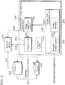
- FIG. 2 is a block diagram illustrating a stereoscopic image aligning apparatus 200 according to an embodiment of the present invention.
- the stereoscopic image aligning apparatus 200 includes: an image pair obtaining unit 205; an image alignment module 208; an output unit 210; and an internal buffer 212.
- the image pair obtaining unit 205 obtains an image pair including a left-eye image and a right-eye image that corresponds to the left-eye image.
- the image pair obtaining unit 205 may obtain the image pair from a capturing device (not illustrated) that includes an image sensor and a lens, or may obtain the image pair through a storage media, a network, or the like.
- the image pair obtaining unit 205 may obtain, as the image pair, two images captured at the same time by a capturing device which includes one of (i) two image sensors and two lenses, (ii) one image sensor and two lenses, and (iii) two image sensors and one lens.
- the image pair obtaining unit 205 may obtain, as the image pair, two images captured at different times from different viewpoints using one image sensor and one lens.
- the image pair obtaining unit 205 includes a storage media reader 202 and an image decoder 204.
- image data that is an image pair is obtained from a storage media such as an SD memory card, for example
- the storage media reader 202 obtains the image data from the storage media.
- the image decoder 204 decodes the image data, as necessary. It is to be noted that the image decoder 204 may decode coded data obtained through the network, for example.
- the image pair obtaining unit 205 may decode an encoded image group in the cases where (i) the image group including a left-eye image and a right-eye image is encoded and stored in a memory card or (ii) the image group is encoded and transmitted through the network from an external device.
- the image alignment module 208 performs image transformation to align the not-encoded image pair S23. Intermediate data associated with alignment processing is recorded in the internal buffer 212. The aligned image pair S25 is sent to the output unit 210.
- the output unit 210 outputs the image pair including the image transformed by the alignment. More specifically, the output unit 210 adjusts an output image format according to a preferable output type. For example, the output unit 210 may adjust the image format to match a display format displayable by the display device 214 so that the display device 214 can carry out display.
- Such formats may include a format for auto-stereoscopic device for viewing without glasses, gray/color anaglyph (viewing with glasses), interlaced format, checker-board format, and other formats for time-sequential stereoscopic display device viewed using active shutter glasses.
- the aligned image pair S26 may be stored/transmitted using a storage/transmission device 216.
- Examples of storage device include but are not limited to flash-based memory card, hard drives, and optical drives.
- Examples of transmission device include but are not limited to HDMI interface, USB interface, wireless interface and direct-to-printer interface.
- the storage or transmission device may optionally consist of lossless or lossy compression.
- the aligned image pair S26 can also be output for printing at a printer 218.
- the printer 218 may include a lenticular sheet for constructing the illusion of depth on a printed image.
- the stored image at storage/transmission device 216 may be directly sent to the printer 218, or sent to the display device 214 via a signal S27.
- a feedback signal S29 that can include display width may be fed back to the image alignment module 208, as necessary.
- the image alignment module 208 and other internal modules included by the stereoscopic image aligning apparatus 200 are typically implemented in the form of IC (Integrated Circuits), ASIC (Application-Specific Integrated Circuits), LSI (Large Scale Integration), DSP (Digital Signal Processor), or implemented by any CPU based processor and machine including PC.
- IC Integrated Circuits
- ASIC Application-Specific Integrated Circuits
- LSI Large Scale Integration
- DSP Digital Signal Processor
- Each of these modules can be in many single-function LSIs, or also can be in one integrated LSI.
- the name used here is LSI, but it may also be called IC, system LSI, super LSI, or ultra LSI in accordance with the degree of integration.
- ways to achieve integration is not only LSI, but also special circuit or general purpose processor and so forth can achieve the integration.
- the stereoscopic image aligning apparatus 200 may be incorporated into a display device capable of displaying a stereoscopic image such as a liquid crystal display device or a plasma display device with time sequential image display, a display device with attached lenticular lens layer, or other types of display devices.
- a display device capable of displaying a stereoscopic image such as a liquid crystal display device or a plasma display device with time sequential image display, a display device with attached lenticular lens layer, or other types of display devices.
- the stereoscopic image aligning apparatus 200 may also be implemented in a digital media player device such as a digital video disc player, a blu-ray® disc player, and other types of digital media player.
- a digital media player device such as a digital video disc player, a blu-ray® disc player, and other types of digital media player.
- the implementation of the stereoscopic image aligning apparatus 200 in other types of device is also possible and does not limit the scope of the present invention.
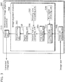
- FIG. 3 is a block diagram illustrating a detailed functional configuration of the image alignment module 208 according to the present embodiment.
- the image alignment module 208 includes: a corresponding point detecting unit 252; a first matrix computing unit 254; a second matrix computing unit 256; a matrix combining unit 258; a transforming unit 260; a blur region detecting unit 220; and a viewing zone computing unit 262.
- the corresponding point detecting unit 252 detects a corresponding point that represents a set of a first point and a second point.
- the first point is included in a first image that is one of the image pair obtained by the image pair obtaining unit 205.
- the second point is a point (i) included in a second image that is the other one of the image pair and (ii) corresponding to the first point.
- the blur region detecting unit 220 detects a blur region in the image pair.
- the method of detecting a blur region can be optionally determined.
- a blur region detecting method for identifying a block including a blur by dividing an image into blocks and detecting, for each of the blocks, the rate of a portion in which a change in concentration of pixels aligned in the same direction may be used.
- the corresponding point detecting unit 252 detects a corresponding point from regions other than the region identified as the blur region in the image pair.
- the first matrix computing unit 254 computes a homography transformation matrix for transforming the first point such that a vertical parallax between the first point and the second point is the smallest and an epipolar constraint is satisfied. It is to be noted that the vertical parallax is a difference in vertical position values. The details will be described later.
- the second matrix computing unit 256 computes a skewing transformation matrix for transforming, again, a third image that is the first image transformed by the homography transformation matrix computed by the first matrix computing unit 254, such that a coordinate system of the third image has orthogonality and the third image has the same aspect ratio as the aspect ratio of the first image. The details will be described later.
- the viewing zone computing unit 262 computes a viewing zone that is a region common to the first image and the second image. It is to be noted that, when the viewing zone is computed, it is preferable that the second matrix computing unit 256 computes the skewing transformation matrix such that a coordinate system of a portion in the viewing zone in the third image, instead of the entire portion of the third image, has the orthogonality and the same aspect ratio as an aspect ratio of a portion included in the viewing zone in the first image. The details will be described later.
- the matrix combining unit 258 generates a combined transformation matrix by combining the homography transformation matrix and the skewing transformation matrix.
- the transforming unit 260 transforms the first image using the combined transformation matrix.
- the image pair including the third image and the second image which are transformed by the image alignment module 208 as described above is output as a corrected image pair from the output unit 210.
- the configuration of the image alignment module 208 is described above with reference to FIG. 3 .
- FIG. 4a is a flow chart illustrating an operation performed by the image alignment module 208 according to the present embodiment.
- the image pair obtaining unit 205 obtains an image pair, thereby inputting the image pair to the stereoscopic image aligning apparatus 200.
- the corresponding point detecting unit 252 detects corresponding points of the image pair.
- Step S304 can be skipped for speeding up the processing time if a sensor such as a Gyro sensor is used to derive the rotation amount between the two image capturing positions when the two images included in the image pair are captured. More specifically, the corresponding point detecting unit 252 computes a rotation parameter and a shift parameter used for generating the homography transformation matrix by the first matrix computing unit 254 so as to match an output from the Gyro sensor that outputs information corresponding to a rotation angle, thereby reducing the processing time for computing the matrix and improving accuracy.
- a sensor such as a Gyro sensor
- Step S306 the first matrix computing unit 254 computes a fundamental matrix (F matrix) using the corresponding points.
- Step S308 the first matrix computing unit 254 computes a homography transformation matrix using the corresponding points. The purpose is to find a matrix which will transform one of the images such that the vertical parallax of the correspondent points becomes the smallest and the epipolar constraint is satisfied.
- Step S310 the second matrix computing unit 256 computes a skewing transformation matrix such that the viewing zone of the transformed image remains orthogonal and has the same aspect ratio as the viewing zone before the transformation.
- Viewing zone is the cropped region used for stereoscopic viewing, which contain regions common to both images. Only those corresponding points falling in the common region which is the overlapped region of the left and right images contribute to the computation of the skewing transformation matrix. When other regions are used, the final 3D image quality would not be guaranteed.
- Step S312 the matrix combining unit 258 combines the homography transformation matrix and the skewing transformation matrix.
- Step S314 one of the images in the image pair is transformed according to the combined transformation matrix (combined transformation matrix).
- Step S316 the aligned stereoscopic image pair is output from the output unit 210.
- FIG. 4b shows another flow diagram which includes a blur region detecting step S317(b), a blur region compensation Step S318(b), a parallax adjusting step S319(b), and a user feedback Step S320(b).
- An image pair inputted in step S302(b) is then handled in S304(b) for detecting corresponding points.
- a certain region is targeted for detecting the corresponding points.
- a result of the blur region detecting in Step S317(b) may be used for excluding the blur region from the target region for detecting corresponding points. Only evenly distributed regions around the center may be selected as the target region for detecting corresponding points, for the purpose of complexity reduction or speeding up the feature points extraction.
- the corresponding point detecting unit 252 may select small regions evenly distributed within a predetermined area extending from the center of each of the first image and the second image which are included in the image pair, and detect the corresponding points from the small regions.
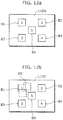
- FIG. 12a and FIG. 12b shows such a configuration, which will be described in the latter part of the present embodiment.
- Step S306(b), Step S308(b), and Step S310(b) the first matrix computing unit 254 and the second matrix computing unit 256 generate a warping matrix by excluding any points in the blur region, using only those selected candidate points.
- Step S318(b) the blur region or a blur object in one frame is compensated or shifted back by referring to the same blur region or blur object in another frame. Then, the resultant image will be subjected to warping in Step S314(b).
- Step S319(b) a parallax or a 3D effect such as a pop-up effect (effect in the direction that an image pops up) or deep-in effect (effect in the direction that an image sinks) can be adjusted by changing the baseline or other parameters, with the feedback from Step S320(b).
- a parallax or a 3D effect such as a pop-up effect (effect in the direction that an image pops up) or deep-in effect (effect in the direction that an image sinks) can be adjusted by changing the baseline or other parameters, with the feedback from Step S320(b).
- the feedback user interaction, for example by pressing a 3D display button (as shown in FIG.11 ) is carried out to feedback to Step S319(b), or automatic detection of a viewing distance is carried out by a distance sensors or 2-camera system to feedback to Step S319(b).
- the output unit 210 may perform and output image processing on an image pair such that the 3D effect decreases as the distance from a user is shorter.
- user feedback can be carried out through pressing a 3D display button and a feedback signal will be sent to the 3D processing engine shown in FIG. 11 .
- “3D disparity” button is pressed up and down for more depth or less depth according to user's viewing distance and user eye's acceptance, or "pop-up” or “deep-in” is pressed to adjust the 3D effect of the content.
- the output unit 210 may obtain information on the size of a display device and output after performing image processing on an image pair such that the 3D effect is reduced as the display device is larger.
- the output unit 210 obtains adjustment information that indicates at least one of an input operation from the viewing user, the size of the display device, and the distance between the display device and the viewing user, and adjusts and outputs, based on the adjustment information, at least one of the parallax between the third image and the second image, the 3D pop-up effect, and the 3D deep-in effect.
- the output unit 210 when adjusting the 3D effect such as the 3D pop-up and the 3D deep-in effect, the output unit 210, specifically, adjusts the parallax between the left and right images included in the image pair. For example, with crossed parallax with which a right-eye image is, with respect to a left-eye image, placed on the left side of the left-eye image, the output unit 210 can strengthen the 3D pop-up effect by increasing the crossed disparity; that is, as the right-eye image is placed further leftward with respect to the left-eye image.
- the corresponding point detecting unit 252 may divide an image 1100 into five sub-blocks; that is, B1, B2, B3, B4, and B5, as shown in FIG. 12a ,.
- These blocks (or some of the blocks) may be used for features detection, descriptors calculation, and correspondence point determination. In this case, the processing for whole image is not required. This accelerates the computation time of the system. Furthermore, these blocks could help to improve the accuracy of the transformation matrix and speed up the desirable correspondences selection. In addition, in the case of homogenous block, there are usually no useful features. Thus, a homogenous block should be omitted. Considering block B1 in FIG.
- non-homogenous block around B1 will be selected (for example B1' when it is non-homogenous block). This is to make sure that all the selected blocks contain useful features.
- Other schemes for image region selection may be used based on the above premise.
- a block when a block is homogenous, it means that variation of image information included in the block is small. For example, when (i) the number of pixels whose pixel values differ, to the extent equal to or more than a predetermined threshold, from pixel values of adjacent pixels in a block (so-called an edge portion) is smaller than a predetermined threshold or (ii) a median value or an average value of a spatial frequency is smaller than a predetermined threshold, the block may be determined as homogenous and other blocks may be determined as non-homogenous.
- the conventional methods can arbitrarily be used for the correspondent point detecting method performed by the corresponding point detecting unit 252. For example, each of the images in an image pair is divided into predetermined blocks having the same size and an edge pair included in each of the blocks is extracted. Then, the degree of similarity (for example, least sum of squares, likelihood, AIC, and the like) is computed for each of the edges and a point included in the edge that has the highest degree of similarity is detected as a correspond point, for example. More specifically, examples of known methods are disclosed by D. Lowe in "object recognition from local scale-invariant features" in "International Conference on Computer Vision” (1999 ) (NPL 1) and by H.
- Step S306 the first matrix computing unit 254 computes a fundamental matrix F using the detected corresponding points. The following simply describes how to obtain the fundamental matrix F.
- I l x l y 1
- the ninth vector u is estimated under the constrained condition that an inner product is zero, using the ninth vector data ⁇ ⁇ ⁇ generated by the corresponding points (these corresponding points include errors in practice) detected by the corresponding point detecting unit 252.
- the fundamental matrix F can be obtained using the maximum likelihood estimation method, with which u is determined with numerical computation such that the likelihood is the maximum. More specifically, the fundamental matrix can be obtained with various methods such as R. Hartley and A. Zisserman, Multiple View Geometry in Computer Vision, Cambridge University Press, London, 2000 (NPL 3 ); X. Armangué and J. Salvi, "overall view regarding fundamental matrix estimation," Image and Vision Computing, Vol. 21, 2003, pp. 205-220 (NPL 4 ); and Z. Zhang, “Determining the epipolar geometry and its uncertainty: a review," International Journal of Computer Vision, Vol. 27, 1998, pp. 161-198 (NPL 4 ).
- the second matrix computing unit 256 computes the homography transformation matrix for warping one of the images in the image pair. Either of the images can be chosen. In this embodiment, the right-eye image is chosen to be warped. However, it does not affect the scope or spirit of the invention if the left-eye image is chosen. There may be an adaptive algorithm to select a left-eye image or a right-eye image for warping based on certain criteria. The criteria is, for example, which one of the left-eye image and the right-eye image is more horizontal, which one of the left-eye image and the right-eye image is sharper, or which one of the left-eye image and the right-eye image contains the object of interest, and so on.
- the present invention uses the epipolar geometry compatible homography transformation, or in other words, homography which is consistent or compatible with the fundamental matrix (see NPL 3). This limits the degree of freedom to 3 instead of 8 for the normal homography transformation.
- F is the 3x3 fundamental matrix F computed in Step S306.
- [a] ⁇ b is cross product and means a ⁇ b.
- V T is the 1x3 vector containing the parameters of 3 degrees of freedom.
- the first matrix computing unit 254 finds H that is parameterized by V T such that the vertical parallax between the correspondent points is minimized.
- v that satisfies Expression 3 is computed. It is assumed here that X L is the list of corresponding points in the left image and X R is the list of corresponding points in the right image. Expression 3 is shown below. [Math. 3] min y_component_of X L ⁇ y_component_of H ⁇ X R
- y_component_of (X) represents a vertical coordinate component of the point X.
- the first matrix computing unit 254 can determine the parameter V T with numerical computation, using corresponding points (X L and X R ). For example, the least square method can be used for determining v that minimizes Expression 3. Another method to find H is to solve for H for each pair of correspondent points and then take the average.
- Step S310 the details for computing a skewing transformation matrix in step S310 are disclosed here.
- the homography transformation matrix computed in Step S308 does not constrain the parallax in the x direction. Therefore, since the image transformed through the homography transformation using H can be skewed in some cases and thus there is a need to correct the skew of the image by performing a skewing transformation.
- To compute the amount of skew the aspect ratio and the orthogonality of the viewing zone are restored according to an implementation of the present invention.
- the terms "viewing zone”, “aspect ratio”, and “orthogonality" are explained using FIG 6a and FIG 6b .
- FIG. 6a depicts a left-eye image 502 and a right-eye image 504.
- the inner rectangles 506 and 508 outline the region common to the both images. Regions outside the inner rectangles 506 and 508 appear in only one of the images. For stereoscopic viewing, these regions are not comfortable because the regions are seen by only one of the eyes and the human brain cannot extract parallax information for allowing a perception of depth.
- the inner rectangles 506 and 508 are termed the viewing zones.
- FIG. 6b depicts a pre-transformation image 510, and a post-transformation image 512 for one of the left and right images.
- a pre-transformation viewing zone 514 has a certain aspect ratio which may be defined by the ratio of the distance between points 518 and 522 to the distance between points 520 and 524.
- the angle 526 is also orthogonal.
- a post-transformation viewing zone 516 may have different aspect ratio similarly defined by the warped points 528, 530, 532, and 534.
- the angle 540 does not have to be orthogonal.
- the shearing transformation matrix is computed to restore the orthogonality and the aspect ratio.
- the following describes in more detail the method of computing the shearing transformation matrix that is the skewing transformation matrix computed by the second matrix computing unit 256.
- the matrix S represented by Expression 4 is a matrix for obtaining a right-eye image 354 in which coordinate axes are orthogonalized by restoring a right-eye image 352 that is a result of transforming a right-eye image 350 by the matrix H computed by the first matrix computing unit 254.
- the points corresponding in the right-eye image 350, the right-eye image 352, and the right-eye image 354 are as below. That is, a point a in the right-eye image 350 corresponds to a point a' in the right-eye image 352, and a point a' corresponds to a point a" in the right-eye image 354.
- a line segment a"c" 355 and a line segment c"d" 356 in the image 354 are orthogonalized. Furthermore, since the aspect ratio of the right-eye image 354 matches the aspect ratio of the right-eye image 352, the ratio of the length of the line segment a"c" 355 to the length of the line segment b"d" 356 matches the ratio of the length h 0 of a line segment ac to the length w 0 of a line segment bd.
- the second matrix computing unit 256 computes variables s1 and s2 included in the skewing transformation matrix S such that both of two constrained conditions indicated in Expression 5 below are satisfied.
- the centroid of the corresponding points in the left-eye image is computed.
- the corresponding points in the right-eye image are transformed and the centroid of the transformed corresponding points is computed.
- the difference between the centriods is computed.
- a value in the vertical direction of the difference between the centriods corresponds to a vertical difference 536 in FIG. 6a .
- a value in the horizontal direction of the difference between the centriods corresponds to a horizontal difference 538 in FIG. 6a .
- the homography transformation matrix and shearing transformation matrix are computed using the correspondent points.
- the image itself has not been warped. It is preferred to combine the homography transformation matrix and shearing transformation matrix before applying one transformation operation rather than two separate transformation operations.
- Step S308 to Step S314 The effects of processes in Step S308 to Step S314 described above will be again described with reference to FIG. 14 .
- FIG. 14 is a conceptual diagram illustrating an image of image conversion processing using the homography transformation matrix H and the skewing transformation matrix S.
- a viewing zone 362 included in the left-eye image plane and a viewing zone 364a included in the right-eye image plane are the viewing zones of the left and right images included in the image pair obtained by the image pair obtaining unit 205 according to the present embodiment.
- a point 372 included in the viewing zone 362 and a point 378 included in the viewing zone 364a are points imaged on the left-eye image plane and the right-eye image plane when a point 370 is viewed from a left focal point c' and a right focal point c, respectively.
- the point 372 and the point 378 are corresponding points.
- the vertical positions of the point 372 and the point 378 are significantly different. Likewise, the vertical positions of other corresponding points are significantly different.
- the viewing zone 364b is an image obtained by transforming the viewing zone 364a using the homography transformation matrix H. With this transforming, the vertical positions of the corresponding point of the viewing zone 362 and the viewing zone 364b matches. For example, the vertical positions of the point 372 and the point 378 that is the corresponding point of the point 372 are the same.
- the coordinate axes are not orthogonalized but skewed.
- An image obtained by transforming the viewing zone 364b using the skewing transformation matrix S is the viewing zone 364c.
- the corresponding points of the viewing zone 364c and the viewing zone 362 have the same vertical position and the orthogonality of the coordinates in the viewing zone is maintained.
- the first matrix computing unit 254 computes the homography transformation matrix H.
- the second matrix computing unit 256 computes the skewing transformation matrix S.
- the matrix combining unit 258 computes the matrix H s .
- the transforming unit 260 performs transforming using the matrix H s on the viewing zone included in one of the images of the obtained image pair (for example, the viewing zone 364a).
- Embodiment 2 according to the present invention, with reference to FIG. 7 .
- the image alignment module 208 is included in a capturing device. It is to be noted that an image alignment module 1246 has the same configuration as the configuration of the stereoscopic image aligning apparatus 200
- FIG. 7 is a schematic block diagram of a capturing device 1200 according to another embodiment of the present invention.
- the capturing device 1200 includes an optical system 1202, an image sensor 1204, an ADC (Analog-to-Digital Converter) 1206, an image processor 1208, a microcomputer 1210, an external memory 1212, a driver controller 1220, an OIS (Optical Image Stabilizer) sensor 1218, an operation portion 1222, a storage/transmission device 1216, and a display device 1214.
- the image processor 1208 includes an internal memory 1240, an image alignment module 1246, a raw image processor 1242, and a color image processor 1244. Other components such as a microphone and a speaker are not shown, but this does not limit the scope and spirit of the present invention.
- the optical system 1202 may include components such as lenses or a set of lens, zoom/focus mechanisms, actuators, shutters, and apertures for controlling the light signal reaching the image sensor 1204.
- the image sensor 1204 accumulates an incoming light signal and converts the light signal into an electrical signal in response to the control of the microcomputer 1210.
- the electrical signal is converted into digital data (raw image data) by the ADC 1206 and stored in the internal memory 1240 or the external memory 1212.
- the raw image data may contain a stereoscopic image pair obtained by capturing the left and right images sequentially from different viewpoints.
- the raw image processor 1242 may obtain the raw image data from the internal memory 1240 (or the external memory 1212) and may perform many pre-processing (not shown), such as noise reduction, linearity correction, white balance, and gamma correction, and output the pre-processed raw image.
- This pre-processed raw image can be stored or transmitted by the storage/transmission device 1216.
- the pre-processed raw image can also be processed by the color image processor 1244 to generate a color image, such as RGB or YCbCr.
- the color image processor 1244 may include color interpolation, color correction, tonal rage adjustment, color noise reduction, and etc, for generating preferred color image.
- the image alignment module 1246 takes in the color images of the stereoscopic image pair and aligns the color images.
- the aligned stereoscopic image pair that is output can be displayed by the display device 1214, such as a liquid crystal monitor with attached lenticular lens layer capable of displaying a stereoscopic image for 3D viewing.
- the images can also displayed in 2D.
- the aligned stereoscopic image pair that is output can also be stored in the storage/transmission device.
- the pre-processed raw images and the output images may be compressed by a compression unit (not shown) before storing/transmitting by the storage/transmission device 1216.
- Examples of storage device include but are not limited to flash-based memory card, hard drives, and optical drives.
- Examples of transmission device include but are not limited to HDMI interface, USB interface, wireless interface and direct-to-printer interface.
- the storage or transmission device may optionally consist of lossless or lossy compression.
- the optical system 1202 may be controlled by the driver controller 1220.
- the driver controller 1220 is controlled by the microcomputer 1210.
- the operation portion 1222 receives a user operation input and sends the electrical signal to the microprocessor 1210 to control the related modules, such as the driver controller 1220, the image sensor 1204, the image processor 1208, corresponding to the user input.
- the OIS sensor 1218 detects the motion due to hand shaking or camera motion and sends the electrical signal to the microcomputer 1210.
- the microcomputer 1210 controls the driver controller 1220 to control actuators or the like in the optical system 1202 for moving the lenses so as to compensate for the motion, thus reducing blur effect caused by hand shaking or camera motion.
- the image processor 1208, the image alignment module 1246, and the modules within are typically achieved in the form of IC (Integrated Circuits), ASIC (Application-Specific Integrated Circuits), or LSI (Large Scale Integrated) circuits.
- IC Integrated Circuits
- ASIC Application-Specific Integrated Circuits
- LSI Large Scale Integrated circuits
- Each of these modules can be in plural single-function LSIs, or also can be in one integrated LSI.
- the name used here is LSI, but it may also be called IC, system LSI, super LSI, or ultra LSI in accordance with the degree of integration.
- ways to achieve integration is not only LSI, but special circuit or general purpose processor and so forth can also achieve the integration. This includes a specialized microprocessor such as DSP (Digital Signal Processor) that can be directed by the program instruction.
- DSP Digital Signal Processor
- FPGA Field Programmable Gate Array
- reconfigurable processor that can re-configure the connection or configuration of LSI can be used for the same purpose.
- a brand-new technology may replace LSI. The integration can be done by that technology.
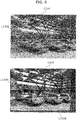
- FIG. 8 is an example of resulting images showing the effect of the stereoscopic image aligning apparatus 200 according to Embodiment 1 of the present invention.
- the resulting image 13LR shows an overlay image between a left-eye image and a right-eye image of a stereoscopic image pair before image alignment. Furthermore, a difference lines (e.g. L1302) indicating the correspondences (misalignment) between the images are superimposed and indicated on the overlay image. It can be seen, from the resulting image 13LR, that the difference lines extend both in the vertical direction and the horizontal direction due to hand movement and are not aligned.
- the stereoscopic image pair of the resulting image 13LR is displayed for 3D viewing, the displayed image can cause eyestrain and visual discomfort to an observer.
- the resulting image 14LR shows an overlay image between left image and the right image of a stereoscopic image pair after image alignment according to an implementation of the present invention. It can be seen, from the resulting image 14LR that the difference lines (L1304) are well aligned (the image pair is well aligned). In addition, the line L1306 indicates a cropping region. This aligned stereoscopic image pair can produce very comfortable 3D viewing when the image pair is displayed. Therefore, the effectiveness of the present invention is verified by FIG. 8 .
- the stereoscopic image aligning apparatus 200 may be used for an image capturing apparatus operating in multi-shot mode. In such mode, multiple images are automatically captured when the user press a button. When the user moves the camera during multi-shot capturing, images of the same scene at different view points are captured. An image pair can be selected from the plurality of images. Criteria for selection can be based on the correspondent points. It is preferred to select an image pair with a sufficient number of correspondent points to input to the image alignment module. Method to detect correspondent points is disclosed in Embodiment 1 as described above. The time interval between each capture can be set by a timer. Each capture can also be triggered by motion of the apparatus. Gyro sensors or accelerometers can be used to determine such movement. It is preferred to trigger the capture when the capturing apparatus has moved a predetermined distance such that disparity is sufficient for stereoscopic viewing.
- objects are at different depths in a scene, in some cases. If the object is nearer, the distance for moving the apparatus should be smaller, and if the object is further, the distance for moving the apparatus should be larger. This distance can be adaptively computed based on the depth of the object. One method to determine the depth is by the focus.
- the stereoscopic image aligning apparatus 200 according to Embodiment 1 can be used in a video capturing apparatus with which the current image is paired with one of the neighboring images to form an image pair.
- stereoscopic video can be produced from a normal 2D video.
- FIG. 9 the application possibility is shown.
- a normal camera or a mobile phone is used to capture more than two images and stored in an SD card or other memory card.
- the 3D image alignment can be conducted inside the camera or the mobile phone.
- the 3D image alignment can also be conducted in any player or display device by embedding the 3D image alignment module 208 in the Hardware of the player or the display. It is also possible to conduct the 3D image alignment by a PC or a server before showing onto a 3D display.
- the feedback signal S29 in FIG. 2 could be the viewing distance from the viewer to the display.
- the feedback signal S29 can be obtained automatically or via user interaction.
- the image alignment module 208 can adjust the baseline of the left and right images during or after image warping or transformation.
- An API Application Interface
- an external button on the display can be made just like those buttons to adjust display contrast or brightness.
- a user can adjust their viewing conformability and the 3D effect, and then sends the user's request to the image alignment module 208.
- the above configuration can be applied to other 3D display devices to make a user interface between a 3D processing module and a user.
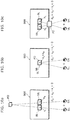
- FIG. 10a, FIG. 10b, and FIG. 10c show detailed explanations for different 3D effects.
- FIG. 10a the positive parallax is shown.
- a left object 9L that is the left-eye image is displayed on the left side of a display screen 900 and a right object 9R that is the right-eye image is displayed on the right side of the display screen 900.
- the observer perceives the object PO as being behind the display screen.
- the perceived depth of an object can be controlled by d X .
- the depth perceived is larger as d X increases, while the depth perceived is smaller as d X decreases.
- FIG. 10b the zero parallax is shown.
- the left object 9L and the right object 9R are displayed on top of each other, on the display screen 900. In this case, the observer perceives the object PO as being on the display screen.
- the negative parallax is shown.
- the left object 9L is displayed on the right side of the display screen 900 and the right object 9R is displayed on the left side of the display screen 900.
- d X the horizontal disparity
- the interocular e the distance between the left eye EL and the right eye ER.
- the interocular e is in a range of 50 mm - 70 mm (65 mm in average). This means that the physical disparity between the left and right images on the display screen should not exceed the distance e.
- the stereoscopic image aligning apparatus 200 produces the same advantageous effects even when not all of the components described above are included.
- the stereoscopic image aligning apparatus 200 does not have to include the blur region detecting unit 220. This is because it is possible to detect corresponding points from an image including a blur, as well. It is to be noted that an image with lesser blur is preferable in detecting corresponding points. Thus, increased accuracy in detecting corresponding points can be expected with the blur region detecting unit 220, with a capturing condition where a large amount of hand movement is involved, for example.
- the stereoscopic image aligning apparatus 200 does not have to include the second matrix computing unit 256.
- the advantageous effects of the present invention can be produced without the second matrix computing unit 256, by storing a predetermined skewing transformation matrix by the transforming unit 260 and applying the skewing transformation matrix to the third image, for example.
- the transforming unit 260 transforms the first image using the homography transformation matrix computed by the first matrix computing unit 254.
- the stereoscopic image aligning apparatus 200 does not have to include the viewing zone computing unit 262. It can be said generally that an region common to the left image the and right image does not significantly change every time.
- the second matrix computing unit 256 can determine a processing region in an image without the viewing zone calculating unit 262, by following a predetermined rule, for example, by specifying, as a viewing zone, a region that occupies 80% on the right of the left-eye image and a region that occupies 80% on the left of the right-eye image.
- the viewing zone can be specified more accurately by including the viewing zone calculating unit 262. As a result, it is possible to provide an image with more natural stereoscopic effects.
- the stereoscopic image aligning apparatus 200 does not have to include the matrix combining unit 258.
- the stereoscopic image aligning apparatus 200 does not include the second matrix computing unit 256, it is not necessary to include the matrix combining unit 258.
- the transforming unit 260 can perform transformation processing on the first image by sequentially using the homography transformation matrix and the skewing transformation matrix stored in a storage region. Therefore, it is possible to produce the same advantageous effect of the invention without performing the combining performed by the matrix combining unit 258.
- the image pair obtaining unit 205 may (A) obtain plural image pair candidates, (B) specify, for each of the image pair candidates, a common viewing zone that is a viewing zone common to each of the other image pair candidates and obtain quality information that is information related to at least one of the amount of light, brightness, color, and definition, and (C) select, as the image pair, the image pair candidate having the highest image quality indicated by the quality information.
- A obtain plural image pair candidates
- B specify, for each of the image pair candidates, a common viewing zone that is a viewing zone common to each of the other image pair candidates and obtain quality information that is information related to at least one of the amount of light, brightness, color, and definition
- C select, as the image pair, the image pair candidate having the highest image quality indicated by the quality information.
- part or all of the functions of the stereoscopic image aligning apparatus 200 according to Embodiments 1 and 2 of the present invention may be implemented by executing a program by a processor such as a CPU.
- the present invention may be the above-described program or a recording medium on which the above-described program is recorded. Furthermore, it should be understood that such a program can be distributed via a transmission medium such as the Internet.
- the present invention can be applied to a stereoscopic image aligning apparatus and the like which detects corresponding points from plural image pairs and aligns the image pairs to meet a certain criterion.
- the present invention can be applied particularly to a stereoscopic image aligning apparatus and the like, which aligns image pairs to allow stereoscopic viewing on a stereoscopic display device.
Claims (17)
- Appareil d'alignement d'image stéréoscopique (200), comprenant :une unité d'obtention de paire d'images (205) configurée pour obtenir une paire d'images comportant une image d'oeil gauche et une image d'oeil droit qui correspond à l'image d'oeil gauche ;une unité de détection de point correspondant (252) configurée pour détecter un ensemble composé d'un premier point et d'un deuxième point, le premier point étant compris dans une première image qui est une des images de la paire d'images, et le deuxième point étant compris dans une deuxième image qui est l'autre image de la paire d'images et correspondant au premier point ;une première unité de calcul de matrice (254) configurée pour calculer une matrice fondamentale au moyen du deuxième point correspondant détecté et calculant une matrice de transformation homographique pour transformer le premier point de telle sorte que le premier point et le deuxième point présentent la même valeur de position verticale et qu'une contrainte épipolaire soit satisfaite ;une unité de transformation (260) configurée pour transformer la première image au moyen de la matrice de transformation homographique en une troisième image ; etune unité de sortie (210) configurée pour délivrer la troisième image et la deuxième image, la troisième image étant la première image transformée.
- Appareil d'alignement d'image stéréoscopique (200) selon la revendication 1,
dans lequel ladite unité d'obtention de paire d'images (205) est configurée pour obtenir, en tant que paire d'images, deux images capturées simultanément au moyen (i) de deux capteurs d'image et de deux lentilles, (ii) d'un capteur d'image et de deux lentilles, ou (iii) de deux capteurs d'image et d'une lentille. - Appareil d'alignement d'image stéréoscopique (200) selon la revendication 1,
dans lequel ladite unité d'obtention de paire d'images (205) est configurée pour obtenir, en tant que paire d'images, deux images capturées à différents moments à partir de différents points de vue, au moyen d'un capteur d'image et d'une lentille. - Appareil d'alignement d'image stéréoscopique (200) selon la revendication 1, comprenant en outre:une deuxième unité de calcul de matrice (256) configurée pour calculer une matrice de transformation de désalignement destinée à transformer la troisième image de telle sorte qu'un système de coordonnées de la troisième image présente une orthogonalité et que la troisième image présente un rapport d'aspect identique à celui d'un rapport d'aspect de la première image ; etune unité de combinaison de matrice (258) configurée pour générer une matrice de transformation combinée en combinant la matrice de transformation homographique et la matrice de transformation de désalignement,dans lequel ladite unité de transformation (260) est configurée pour transformer la première image au moyen de la matrice de transformation combinée.
- Appareil d'alignement d'image stéréoscopique (200) selon la revendication 4, comprenant en outre :une unité de calcul de zone d'observation (262) configurée pour calculer une zone d'observation qui est une région commune à la première image et à la deuxième image,dans lequel ladite deuxième unité de calcul de matrice (256) est configurée pour calculer la matrice de transformation de désalignement, de telle sorte qu'un système de coordonnées d'une partie comprise dans la zone d'observation de la troisième image présente l'orthogonalité et que la partie comprise dans la zone d'observation de la troisième image présente un rapport d'aspect identique à celui d'un rapport d'aspect d'une partie comprise dans la zone d'observation de la première image.
- Appareil d'alignement d'image stéréoscopique (200) selon la revendication 1,
dans lequel ladite unité de détection de point correspondant (252) est configurée pour sélectionner des petites régions distribuées uniformément dans une superficie prédéterminée s'étendant d'un centre de la première image et de la deuxième image comprises dans la paire d'images et détecter le point correspondant à partir des petites régions. - Appareil d'alignement d'image stéréoscopique (200) selon l'une quelconque des revendications 1 et 3, comprenant en outre
une unité de détection de région de flou (220) configurée pour détecter une région de flou dans la paire d'images,
dans lequel ladite unité de détection de point correspondant (252) est configurée pour détecter le point correspondant à partir des régions différentes de la région de flou dans la paire d'images. - Appareil d'alignement d'image stéréoscopique (200) selon la revendication 1,
dans lequel ladite unité de sortie (210) est configurée pour obtenir une information de réglage qui indique au moins une parmi une opération d'entrée par un utilisateur en observation, une taille d'un dispositif d'affichage, et une distance entre le dispositif d'affichage et l'utilisateur en observation, et pour régler et délivrer au moins un parmi une parallaxe entre la troisième image et la deuxième image, un effet surgissant tridimensionnel (3D), et un effet de profondeur 3D, sur la base de l'information de réglage. - Appareil d'alignement d'image stéréoscopique (200) selon la revendication 1,
dans lequel ladite unité d'obtention de paire d'images (205) est configurée pour (A) obtenir une pluralité de candidats de paire d'images dont chacun est un candidat pour la paire d'images, (B) spécifier, pour chacun des candidats de paire d'image, une zone d'observation commune qui est une zone d'observation commune au candidat de paire d'image et à un autre candidat de paire d'image, et obtenir une information de qualité qui est une information associée à au moins une parmi une quantité de lumière, une luminosité, une couleur, et une définition, dans la zone d'observation commune, et (C) sélectionner, en tant que paire d'images, un des candidats de paire d'images présentant une qualité d'image très élevée indiquée par l'information de qualité. - Appareil d'alignement d'image stéréoscopique (200) selon la revendication 1,
dans lequel, lorsque (i) un groupe d'images est encodé et mis en mémoire dans une carte mémoire ou (ii) que le groupe d'images est encodé et transmis à partir d'un dispositif externe à travers un réseau, ladite unité d'obtention de paire d'images (205) est configurée pour décoder le groupe d'images encodées, le groupe d'images comprenant l'image d'oeil gauche et l'image d'oeil droit. - Appareil d'alignement d'image stéréoscopique (200) selon la revendication 1,
dans lequel ladite unité de détection de point correspondant (252) est configurée pour calculer un paramètre de rotation et un paramètre de décalage de manière à faire correspondre le paramètre de rotation et le paramètre de décalage à une sortie provenant d'un capteur gyroscopique qui délivre une information correspondant à un angle de rotation, le paramètre de rotation et le paramètre de décalage étant destinés à être utilisés pour la génération de la matrice de transformation homographique. - Appareil d'alignement d'image stéréoscopique (200) selon la revendication 1,
dans lequel ledit appareil d'alignement d'image stéréoscopique (200) est (i) incorporé dans une caméra bidimensionnelle (2D) pour former une caméra 3D, (ii) incorporé dans un écran 3D en tant que moteur de traitement 3D pour convertir un groupe d'images 2D en images 3D ou en vidéo 3D, et (ii) incorporé dans un lecteur ou un enregistreur pour convertir le groupe d'images 2D en images 3D ou en vidéo 3D. - Procédé d'alignement d'image stéréoscopique, comprenant les étampes :d'obtention d'une paire d'images comprenant une image d'oeil gauche et une image d'oeil droit qui correspond à l'image d'oeil gauche ;de détection d'un ensemble composé d'un premier point et d'un deuxième point, le premier point étant compris dans une première image qui est une des images de la paire d'images, et le deuxième point étant compris dans une deuxième image qui est l'autre image de la paire d'images et correspondant au premier point ;de calcul d'une matrice fondamentale au moyen du deuxième point correspondant détecté, etde calcul d'une matrice de transformation homographique destinée à transformer le premier point de telle sorte que le premier point et le deuxième point présentent une même valeur de position verticale et qu'une contrainte épipolaire est satisfaite ;de transformation de la première image au moyen de la matrice de transformation homographique en une troisième image ; etde délivrance de la troisième image et de la deuxième image, la troisième image étant la première image transformée.
- Programme destiné à amener un ordinateur à exécuter le procédé d'alignement d'image stéréoscopique selon la revendication 13.
- Support d'enregistrement lisible sur ordinateur sur lequel le programme selon la revendication 14 est enregistré.
- Circuit intégré comprenant un appareil d'alignement d'image stéréoscopique selon la revendication 1.
- Appareil photo numérique comprenant l'appareil d'alignement d'image stéréoscopique (200) selon la revendication 3.
Applications Claiming Priority (2)
| Application Number | Priority Date | Filing Date | Title |
|---|---|---|---|
| JP2010065185 | 2010-03-19 | ||
| PCT/JP2011/001455 WO2011114683A1 (fr) | 2010-03-19 | 2011-03-14 | Appareil d'adaptation de position d'image en stéréovision, procédé d'adaptation de position d'image en stéréovision et programme correspondant |
Publications (3)
| Publication Number | Publication Date |
|---|---|
| EP2549762A1 EP2549762A1 (fr) | 2013-01-23 |
| EP2549762A4 EP2549762A4 (fr) | 2014-06-25 |
| EP2549762B1 true EP2549762B1 (fr) | 2017-05-03 |
Family
ID=44648797
Family Applications (1)
| Application Number | Title | Priority Date | Filing Date |
|---|---|---|---|
| EP11755876.7A Not-in-force EP2549762B1 (fr) | 2010-03-19 | 2011-03-14 | Appareil d'adaptation de position d'image en stéréovision, procédé d'adaptation de position d'image en stéréovision et programme correspondant |
Country Status (5)
| Country | Link |
|---|---|
| US (1) | US8890934B2 (fr) |
| EP (1) | EP2549762B1 (fr) |
| JP (1) | JP5679978B2 (fr) |
| CN (1) | CN102428707B (fr) |
| WO (1) | WO2011114683A1 (fr) |
Families Citing this family (100)
| Publication number | Priority date | Publication date | Assignee | Title |
|---|---|---|---|---|
| EP3328048B1 (fr) | 2008-05-20 | 2021-04-21 | FotoNation Limited | Capture et traitement d'images au moyen d'un réseau de caméras monolithiques avec des imageurs hétérogènes |
| US8866920B2 (en) | 2008-05-20 | 2014-10-21 | Pelican Imaging Corporation | Capturing and processing of images using monolithic camera array with heterogeneous imagers |
| US11792538B2 (en) | 2008-05-20 | 2023-10-17 | Adeia Imaging Llc | Capturing and processing of images including occlusions focused on an image sensor by a lens stack array |
| WO2011063347A2 (fr) | 2009-11-20 | 2011-05-26 | Pelican Imaging Corporation | Capture et traitement d'images au moyen d'un réseau de caméras monolithique équipé d'imageurs hétérogènes |
| WO2011143501A1 (fr) | 2010-05-12 | 2011-11-17 | Pelican Imaging Corporation | Architectures pour des réseaux d'imageurs et des caméras disposées en réseau |
| US8878950B2 (en) | 2010-12-14 | 2014-11-04 | Pelican Imaging Corporation | Systems and methods for synthesizing high resolution images using super-resolution processes |
| EP2509324A1 (fr) * | 2011-04-08 | 2012-10-10 | Thomson Licensing | Procédé et appareil pour analyser des images stéréoscopiques ou à vues multiples |
| EP2708019B1 (fr) | 2011-05-11 | 2019-10-16 | FotoNation Limited | Systèmes et procédés pour la transmission et la réception de données d'image de caméra réseau |
| WO2013003276A1 (fr) | 2011-06-28 | 2013-01-03 | Pelican Imaging Corporation | Configurations optiques pour utilisation avec une caméra matricielle |
| US20130265459A1 (en) | 2011-06-28 | 2013-10-10 | Pelican Imaging Corporation | Optical arrangements for use with an array camera |
| US20130033713A1 (en) * | 2011-08-02 | 2013-02-07 | Samsung Electronics Co., Ltd | Apparatus and method of forming image, terminal and method of print control, and computer-readable medium |
| US9305361B2 (en) | 2011-09-12 | 2016-04-05 | Qualcomm Incorporated | Resolving homography decomposition ambiguity based on orientation sensors |
| US20130070060A1 (en) | 2011-09-19 | 2013-03-21 | Pelican Imaging Corporation | Systems and methods for determining depth from multiple views of a scene that include aliasing using hypothesized fusion |
| CN107230236B (zh) | 2011-09-28 | 2020-12-08 | 快图有限公司 | 用于编码和解码光场图像文件的系统及方法 |
| US9402065B2 (en) * | 2011-09-29 | 2016-07-26 | Qualcomm Incorporated | Methods and apparatus for conditional display of a stereoscopic image pair |
| US9692991B2 (en) * | 2011-11-04 | 2017-06-27 | Qualcomm Incorporated | Multispectral imaging system |
| KR101888155B1 (ko) * | 2011-11-22 | 2018-08-16 | 삼성전자주식회사 | 디스플레이 장치 및 그 디스플레이 방법 |
| KR101862404B1 (ko) * | 2011-12-09 | 2018-05-29 | 엘지이노텍 주식회사 | 스테레오 영상의 노이즈 제거장치 및 방법 |
| WO2013126578A1 (fr) | 2012-02-21 | 2013-08-29 | Pelican Imaging Corporation | Systèmes et procédés pour la manipulation de données d'image de champ lumineux capturé |
| US9210392B2 (en) | 2012-05-01 | 2015-12-08 | Pelican Imaging Coporation | Camera modules patterned with pi filter groups |
| EP2873028A4 (fr) * | 2012-06-28 | 2016-05-25 | Pelican Imaging Corp | Systèmes et procédés pour détecter des réseaux de caméras, des réseaux optiques et des capteurs défectueux |
| CN104321730B (zh) * | 2012-06-30 | 2019-02-19 | 英特尔公司 | 3d图形用户接口 |
| US20140002674A1 (en) | 2012-06-30 | 2014-01-02 | Pelican Imaging Corporation | Systems and Methods for Manufacturing Camera Modules Using Active Alignment of Lens Stack Arrays and Sensors |
| AU2013305770A1 (en) | 2012-08-21 | 2015-02-26 | Pelican Imaging Corporation | Systems and methods for parallax detection and correction in images captured using array cameras |
| US20140055632A1 (en) | 2012-08-23 | 2014-02-27 | Pelican Imaging Corporation | Feature based high resolution motion estimation from low resolution images captured using an array source |
| US8948497B2 (en) * | 2012-09-04 | 2015-02-03 | Digital Signal Corporation | System and method for increasing resolution of images obtained from a three-dimensional measurement system |
| US9214013B2 (en) | 2012-09-14 | 2015-12-15 | Pelican Imaging Corporation | Systems and methods for correcting user identified artifacts in light field images |
| WO2014052974A2 (fr) | 2012-09-28 | 2014-04-03 | Pelican Imaging Corporation | Création d'images à partir de champs de lumière en utilisant des points de vue virtuels |
| US9148651B2 (en) * | 2012-10-05 | 2015-09-29 | Blackberry Limited | Methods and devices for generating a stereoscopic image |
| CN103792667B (zh) | 2012-10-30 | 2016-06-01 | 财团法人工业技术研究院 | 立体摄像装置、自动校正装置与校正方法 |
| US9143711B2 (en) | 2012-11-13 | 2015-09-22 | Pelican Imaging Corporation | Systems and methods for array camera focal plane control |
| EP2757524B1 (fr) * | 2013-01-16 | 2018-12-19 | Honda Research Institute Europe GmbH | Système et procédé de détection de profondeur pour véhicules autonomes |
| WO2014130849A1 (fr) | 2013-02-21 | 2014-08-28 | Pelican Imaging Corporation | Génération de données comprimées de représentation de champ lumineux |
| US9374512B2 (en) | 2013-02-24 | 2016-06-21 | Pelican Imaging Corporation | Thin form factor computational array cameras and modular array cameras |
| US9638883B1 (en) | 2013-03-04 | 2017-05-02 | Fotonation Cayman Limited | Passive alignment of array camera modules constructed from lens stack arrays and sensors based upon alignment information obtained during manufacture of array camera modules using an active alignment process |
| WO2014138695A1 (fr) | 2013-03-08 | 2014-09-12 | Pelican Imaging Corporation | Systèmes et procédés pour mesurer des informations de scène tout en capturant des images à l'aide de caméras de réseau |
| US8866912B2 (en) | 2013-03-10 | 2014-10-21 | Pelican Imaging Corporation | System and methods for calibration of an array camera using a single captured image |
| US9519972B2 (en) | 2013-03-13 | 2016-12-13 | Kip Peli P1 Lp | Systems and methods for synthesizing images from image data captured by an array camera using restricted depth of field depth maps in which depth estimation precision varies |
| US9888194B2 (en) | 2013-03-13 | 2018-02-06 | Fotonation Cayman Limited | Array camera architecture implementing quantum film image sensors |
| US9106784B2 (en) | 2013-03-13 | 2015-08-11 | Pelican Imaging Corporation | Systems and methods for controlling aliasing in images captured by an array camera for use in super-resolution processing |
| WO2014164550A2 (fr) | 2013-03-13 | 2014-10-09 | Pelican Imaging Corporation | Systèmes et procédés de calibrage d'une caméra réseau |
| US9100586B2 (en) | 2013-03-14 | 2015-08-04 | Pelican Imaging Corporation | Systems and methods for photometric normalization in array cameras |
| US9578259B2 (en) | 2013-03-14 | 2017-02-21 | Fotonation Cayman Limited | Systems and methods for reducing motion blur in images or video in ultra low light with array cameras |
| US9497370B2 (en) | 2013-03-15 | 2016-11-15 | Pelican Imaging Corporation | Array camera architecture implementing quantum dot color filters |
| US9633442B2 (en) | 2013-03-15 | 2017-04-25 | Fotonation Cayman Limited | Array cameras including an array camera module augmented with a separate camera |
| US9445003B1 (en) | 2013-03-15 | 2016-09-13 | Pelican Imaging Corporation | Systems and methods for synthesizing high resolution images using image deconvolution based on motion and depth information |
| US9497429B2 (en) | 2013-03-15 | 2016-11-15 | Pelican Imaging Corporation | Extended color processing on pelican array cameras |
| US10122993B2 (en) | 2013-03-15 | 2018-11-06 | Fotonation Limited | Autofocus system for a conventional camera that uses depth information from an array camera |
| JP2016524125A (ja) | 2013-03-15 | 2016-08-12 | ペリカン イメージング コーポレイション | カメラアレイを用いた立体撮像のためのシステムおよび方法 |
| KR102582420B1 (ko) * | 2013-04-08 | 2023-09-26 | 스냅 아이엔씨 | 멀티-카메라 장치를 사용하는 거리 추정 |
| JP2014207519A (ja) * | 2013-04-11 | 2014-10-30 | ソニー株式会社 | 画像処理装置、画像処理方法、プログラム、および電子機器 |
| US10148929B2 (en) | 2013-04-15 | 2018-12-04 | Htc Corporation | Method of prompting proper rotation angle for image depth establishing |
| US9898856B2 (en) | 2013-09-27 | 2018-02-20 | Fotonation Cayman Limited | Systems and methods for depth-assisted perspective distortion correction |
| CN103996215A (zh) * | 2013-11-05 | 2014-08-20 | 深圳市云立方信息科技有限公司 | 一种实现虚拟视图转立体视图的方法及装置 |
| US9185276B2 (en) | 2013-11-07 | 2015-11-10 | Pelican Imaging Corporation | Methods of manufacturing array camera modules incorporating independently aligned lens stacks |
| WO2015074078A1 (fr) | 2013-11-18 | 2015-05-21 | Pelican Imaging Corporation | Estimation de profondeur à partir d'une texture projetée au moyen de réseaux d'appareils de prises de vue |
| WO2015081279A1 (fr) | 2013-11-26 | 2015-06-04 | Pelican Imaging Corporation | Configurations de caméras en réseau comprenant de multiples caméras en réseau constitutives |
| TWI520098B (zh) | 2014-01-28 | 2016-02-01 | 聚晶半導體股份有限公司 | 影像擷取裝置及其影像形變偵測方法 |
| CN104811688B (zh) * | 2014-01-28 | 2017-09-01 | 聚晶半导体股份有限公司 | 图像获取装置及其图像形变检测方法 |
| US10089740B2 (en) | 2014-03-07 | 2018-10-02 | Fotonation Limited | System and methods for depth regularization and semiautomatic interactive matting using RGB-D images |
| US9247117B2 (en) | 2014-04-07 | 2016-01-26 | Pelican Imaging Corporation | Systems and methods for correcting for warpage of a sensor array in an array camera module by introducing warpage into a focal plane of a lens stack array |
| GB2525170A (en) | 2014-04-07 | 2015-10-21 | Nokia Technologies Oy | Stereo viewing |
| US9521319B2 (en) | 2014-06-18 | 2016-12-13 | Pelican Imaging Corporation | Array cameras and array camera modules including spectral filters disposed outside of a constituent image sensor |
| US9613408B2 (en) * | 2014-09-25 | 2017-04-04 | Intel Corporation | High dynamic range image composition using multiple images |
| CN107077743B (zh) | 2014-09-29 | 2021-03-23 | 快图有限公司 | 用于阵列相机的动态校准的系统和方法 |
| KR101932547B1 (ko) * | 2014-10-23 | 2018-12-27 | 한화테크윈 주식회사 | 카메라 시스템 및 이의 영상 정합 방법 |
| HUP1400600A2 (hu) * | 2014-12-17 | 2016-06-28 | Pi Holding Zrt | Eljárás képszegmens tartalmának lecserélésére |
| CN105744254B (zh) * | 2014-12-30 | 2017-12-29 | 钰立微电子股份有限公司 | 校正导引系统和校正导引系统的操作方法 |
| JP6690637B2 (ja) * | 2015-03-31 | 2020-04-28 | ソニー株式会社 | 医療用観察装置、情報処理方法、プログラム、及びビデオ顕微鏡装置 |
| US10275863B2 (en) * | 2015-04-03 | 2019-04-30 | Cognex Corporation | Homography rectification |
| US9942474B2 (en) | 2015-04-17 | 2018-04-10 | Fotonation Cayman Limited | Systems and methods for performing high speed video capture and depth estimation using array cameras |
| JP6570327B2 (ja) * | 2015-06-05 | 2019-09-04 | キヤノン株式会社 | 制御装置、撮像装置、制御方法、プログラム、および、記憶媒体 |
| EP3348055B1 (fr) * | 2015-09-08 | 2021-05-26 | SZ DJI Technology Co., Ltd. | Système et procédé prenant en charge le fonctionnement d'un affichage en trois dimensions en mode immersion (fpv) |
| US10097747B2 (en) * | 2015-10-21 | 2018-10-09 | Qualcomm Incorporated | Multiple camera autofocus synchronization |
| US9762893B2 (en) * | 2015-12-07 | 2017-09-12 | Google Inc. | Systems and methods for multiscopic noise reduction and high-dynamic range |
| CN109070804B (zh) * | 2016-04-14 | 2021-09-21 | 金泰克斯公司 | 视觉校正车辆显示器 |
| US10796425B1 (en) * | 2016-09-06 | 2020-10-06 | Amazon Technologies, Inc. | Imagery-based member deformation gauge |
| KR102529928B1 (ko) | 2016-09-22 | 2023-05-09 | 삼성전자주식회사 | 스테레오 카메라의 교정 방법 및 이를 수행하는 전자 장치 |
| US10284761B2 (en) | 2016-11-17 | 2019-05-07 | Motorola Mobility Llc | Multi-camera capture of a high dynamic range image |
| CN107046638A (zh) * | 2016-12-30 | 2017-08-15 | 无锡易维视显示技术有限公司 | 单摄像头的3d影像拍摄方法 |
| US10250794B2 (en) | 2017-01-04 | 2019-04-02 | Motorola Mobility Llc | Capturing an image using multi-camera automatic focus |
| US10169671B2 (en) | 2017-02-17 | 2019-01-01 | Motorola Mobility Llc | Face detection with temperature and distance validation |
| US10250795B2 (en) | 2017-03-15 | 2019-04-02 | Motorola Mobility Llc | Identifying a focus point in a scene utilizing a plurality of cameras |
| CN107147898B (zh) * | 2017-05-10 | 2019-02-05 | 宁波视睿迪光电有限公司 | 一种3d显示屏对位系统和方法 |
| US10482618B2 (en) | 2017-08-21 | 2019-11-19 | Fotonation Limited | Systems and methods for hybrid depth regularization |
| WO2020097128A1 (fr) | 2018-11-06 | 2020-05-14 | Flir Commercial Systems, Inc. | Co-enregistrement automatique de paires d'images thermiques et visibles |
| CN110223355B (zh) * | 2019-05-15 | 2021-01-05 | 大连理工大学 | 一种基于双重极线约束的特征标志点匹配方法 |
| US11650596B2 (en) * | 2019-05-31 | 2023-05-16 | Cascade Corporation | Load alignment aid |
| CN110533711A (zh) * | 2019-09-04 | 2019-12-03 | 云南电网有限责任公司带电作业分公司 | 一种基于加速稳健特征的高效大尺度立体匹配算法 |
| US11270110B2 (en) | 2019-09-17 | 2022-03-08 | Boston Polarimetrics, Inc. | Systems and methods for surface modeling using polarization cues |
| CN114766003B (zh) | 2019-10-07 | 2024-03-26 | 波士顿偏振测定公司 | 用于利用偏振增强传感器系统和成像系统的系统和方法 |
| CN110969659B (zh) * | 2019-10-31 | 2024-03-15 | 浙江清华长三角研究院 | 一种被动式标记点的空间定位装置和方法 |
| CN114787648B (zh) | 2019-11-30 | 2023-11-10 | 波士顿偏振测定公司 | 用于使用偏振提示进行透明对象分段的系统和方法 |
| US11375180B2 (en) * | 2019-12-10 | 2022-06-28 | Yousseff El Moumni | Video engine for generating an enhanced impression of depth based upon two-dimensioned video content |
| JP7462769B2 (ja) | 2020-01-29 | 2024-04-05 | イントリンジック イノベーション エルエルシー | 物体の姿勢の検出および測定システムを特徴付けるためのシステムおよび方法 |
| KR20220133973A (ko) | 2020-01-30 | 2022-10-05 | 인트린식 이노베이션 엘엘씨 | 편광된 이미지들을 포함하는 상이한 이미징 양식들에 대해 통계적 모델들을 훈련하기 위해 데이터를 합성하기 위한 시스템들 및 방법들 |
| WO2021243088A1 (fr) | 2020-05-27 | 2021-12-02 | Boston Polarimetrics, Inc. | Systèmes optiques de polarisation à ouvertures multiples utilisant des diviseurs de faisceau |
| US11290658B1 (en) | 2021-04-15 | 2022-03-29 | Boston Polarimetrics, Inc. | Systems and methods for camera exposure control |
| US11954886B2 (en) | 2021-04-15 | 2024-04-09 | Intrinsic Innovation Llc | Systems and methods for six-degree of freedom pose estimation of deformable objects |
| US11689813B2 (en) | 2021-07-01 | 2023-06-27 | Intrinsic Innovation Llc | Systems and methods for high dynamic range imaging using crossed polarizers |
Family Cites Families (8)
| Publication number | Priority date | Publication date | Assignee | Title |
|---|---|---|---|---|
| US6191809B1 (en) | 1998-01-15 | 2001-02-20 | Vista Medical Technologies, Inc. | Method and apparatus for aligning stereo images |
| US6606404B1 (en) | 1999-06-19 | 2003-08-12 | Microsoft Corporation | System and method for computing rectifying homographies for stereo vision processing of three dimensional objects |
| GB2372659A (en) | 2001-02-23 | 2002-08-28 | Sharp Kk | A method of rectifying a stereoscopic image |
| JP2003244500A (ja) | 2002-02-13 | 2003-08-29 | Pentax Corp | ステレオ画像撮像装置 |
| US7343035B1 (en) * | 2003-10-20 | 2008-03-11 | Open Invention Network Llc | Method and system for three-dimensional feature attribution through synergy of rational polynomial coefficients and projective geometry |
| DE102006050379A1 (de) * | 2006-10-25 | 2008-05-08 | Norbert Prof. Dr. Link | Verfahren und Vorrichtung zur Überwachung eines Raumvolumens sowie Kalibrierverfahren |
| US8135238B2 (en) * | 2008-06-05 | 2012-03-13 | Kia Sha Managment Liability Company | Free view generation in ray-space |
| EP2494402B1 (fr) * | 2009-10-30 | 2018-04-18 | Hewlett-Packard Development Company, L.P. | Systèmes d'affichage stéréo |
-
2011
- 2011-03-14 EP EP11755876.7A patent/EP2549762B1/fr not_active Not-in-force
- 2011-03-14 CN CN201180002079.6A patent/CN102428707B/zh not_active Expired - Fee Related
- 2011-03-14 US US13/320,640 patent/US8890934B2/en not_active Expired - Fee Related
- 2011-03-14 JP JP2011536681A patent/JP5679978B2/ja not_active Expired - Fee Related
- 2011-03-14 WO PCT/JP2011/001455 patent/WO2011114683A1/fr active Application Filing
Also Published As
| Publication number | Publication date |
|---|---|
| EP2549762A4 (fr) | 2014-06-25 |
| EP2549762A1 (fr) | 2013-01-23 |
| US20120147139A1 (en) | 2012-06-14 |
| US8890934B2 (en) | 2014-11-18 |
| CN102428707A (zh) | 2012-04-25 |
| JP5679978B2 (ja) | 2015-03-04 |
| JPWO2011114683A1 (ja) | 2013-06-27 |
| CN102428707B (zh) | 2015-03-11 |
| WO2011114683A1 (fr) | 2011-09-22 |
Similar Documents
| Publication | Publication Date | Title |
|---|---|---|
| EP2549762B1 (fr) | Appareil d'adaptation de position d'image en stéréovision, procédé d'adaptation de position d'image en stéréovision et programme correspondant | |
| US8908011B2 (en) | Three-dimensional video creating device and three-dimensional video creating method | |
| JP5917017B2 (ja) | 画像処理装置及びその制御方法、並びにプログラム | |
| WO2012086120A1 (fr) | Appareil de traitement d'image, appareil de captation d'image, procédé de traitement d'image et programme | |
| US20120263372A1 (en) | Method And Apparatus For Processing 3D Image | |
| US20130135298A1 (en) | Apparatus and method for generating new viewpoint image | |
| US8659644B2 (en) | Stereo video capture system and method | |
| JP2011064894A (ja) | 立体画像表示装置 | |
| JP2011188004A (ja) | 立体映像撮像装置、立体映像処理装置および立体映像撮像方法 | |
| JP5522018B2 (ja) | 画像処理装置、画像処理方法及び画像処理プログラム | |
| US8982187B2 (en) | System and method of rendering stereoscopic images | |
| US20130258059A1 (en) | Three-dimensional (3d) image photographing apparatus and method | |
| US20110181593A1 (en) | Image processing apparatus, 3d display apparatus, and image processing method | |
| US8970670B2 (en) | Method and apparatus for adjusting 3D depth of object and method for detecting 3D depth of object | |
| WO2012120880A1 (fr) | Dispositif de sortie d'image en trois dimensions et procédé de sortie d'image en trois dimensions | |
| KR20110025083A (ko) | 입체 영상 시스템에서 입체 영상 디스플레이 장치 및 방법 | |
| JP5689693B2 (ja) | 描画処理装置 | |
| JP5871113B2 (ja) | 立体画像生成装置、立体画像生成方法及び立体画像生成プログラム | |
| JP5362071B2 (ja) | 映像処理装置、映像表示装置および映像処理方法 | |
| JP2005072674A (ja) | 三次元画像生成装置および三次元画像生成システム | |
| JP2007189489A (ja) | 立体映像処理装置並びにそのプログラム | |
| JP2015029215A (ja) | 立体画像処理装置 | |
| JP4249188B2 (ja) | 立体画像切出し位置算出装置並びにそのプログラムおよび立体画像切出し装置並びにそのプログラム | |
| JP2007194694A (ja) | 立体映像撮影装置並びにそのプログラム | |
| JP2012147370A (ja) | 撮像装置 |
Legal Events
| Date | Code | Title | Description |
|---|---|---|---|
| PUAI | Public reference made under article 153(3) epc to a published international application that has entered the european phase |
Free format text: ORIGINAL CODE: 0009012 |
|
| 17P | Request for examination filed |
Effective date: 20120606 |
|
| AK | Designated contracting states |
Kind code of ref document: A1 Designated state(s): AL AT BE BG CH CY CZ DE DK EE ES FI FR GB GR HR HU IE IS IT LI LT LU LV MC MK MT NL NO PL PT RO RS SE SI SK SM TR |
|
| DAX | Request for extension of the european patent (deleted) | ||
| RIN1 | Information on inventor provided before grant (corrected) |
Inventor name: ONG, CHIN PHEK Inventor name: LI, BO Inventor name: SHEN, SHENG MEI Inventor name: LASANG, PONGSAK Inventor name: TAGAWA, JUNICHI |
|
| A4 | Supplementary search report drawn up and despatched |
Effective date: 20140526 |
|
| RIC1 | Information provided on ipc code assigned before grant |
Ipc: G03B 35/08 20060101ALI20140520BHEP Ipc: G06T 1/00 20060101ALI20140520BHEP Ipc: H04N 13/02 20060101AFI20140520BHEP Ipc: H04N 13/04 20060101ALI20140520BHEP Ipc: H04N 13/00 20060101ALI20140520BHEP |
|
| RAP1 | Party data changed (applicant data changed or rights of an application transferred) |
Owner name: PANASONIC INTELLECTUAL PROPERTY MANAGEMENT CO., LT |
|
| GRAP | Despatch of communication of intention to grant a patent |
Free format text: ORIGINAL CODE: EPIDOSNIGR1 |
|
| STAA | Information on the status of an ep patent application or granted ep patent |
Free format text: STATUS: GRANT OF PATENT IS INTENDED |
|
| INTG | Intention to grant announced |
Effective date: 20170112 |
|
| GRAS | Grant fee paid |
Free format text: ORIGINAL CODE: EPIDOSNIGR3 |
|
| GRAA | (expected) grant |
Free format text: ORIGINAL CODE: 0009210 |
|
| STAA | Information on the status of an ep patent application or granted ep patent |
Free format text: STATUS: THE PATENT HAS BEEN GRANTED |
|
| AK | Designated contracting states |
Kind code of ref document: B1 Designated state(s): AL AT BE BG CH CY CZ DE DK EE ES FI FR GB GR HR HU IE IS IT LI LT LU LV MC MK MT NL NO PL PT RO RS SE SI SK SM TR |
|
| REG | Reference to a national code |
Ref country code: GB Ref legal event code: FG4D |
|
| REG | Reference to a national code |
Ref country code: AT Ref legal event code: REF Ref document number: 891180 Country of ref document: AT Kind code of ref document: T Effective date: 20170515 Ref country code: CH Ref legal event code: EP |
|
| REG | Reference to a national code |
Ref country code: IE Ref legal event code: FG4D |
|
| REG | Reference to a national code |
Ref country code: DE Ref legal event code: R096 Ref document number: 602011037593 Country of ref document: DE |
|
| REG | Reference to a national code |
Ref country code: NL Ref legal event code: MP Effective date: 20170503 |
|
| REG | Reference to a national code |
Ref country code: AT Ref legal event code: MK05 Ref document number: 891180 Country of ref document: AT Kind code of ref document: T Effective date: 20170503 |
|
| REG | Reference to a national code |
Ref country code: LT Ref legal event code: MG4D |
|
| PG25 | Lapsed in a contracting state [announced via postgrant information from national office to epo] |
Ref country code: LT Free format text: LAPSE BECAUSE OF FAILURE TO SUBMIT A TRANSLATION OF THE DESCRIPTION OR TO PAY THE FEE WITHIN THE PRESCRIBED TIME-LIMIT Effective date: 20170503 Ref country code: FI Free format text: LAPSE BECAUSE OF FAILURE TO SUBMIT A TRANSLATION OF THE DESCRIPTION OR TO PAY THE FEE WITHIN THE PRESCRIBED TIME-LIMIT Effective date: 20170503 Ref country code: ES Free format text: LAPSE BECAUSE OF FAILURE TO SUBMIT A TRANSLATION OF THE DESCRIPTION OR TO PAY THE FEE WITHIN THE PRESCRIBED TIME-LIMIT Effective date: 20170503 Ref country code: NO Free format text: LAPSE BECAUSE OF FAILURE TO SUBMIT A TRANSLATION OF THE DESCRIPTION OR TO PAY THE FEE WITHIN THE PRESCRIBED TIME-LIMIT Effective date: 20170803 Ref country code: GR Free format text: LAPSE BECAUSE OF FAILURE TO SUBMIT A TRANSLATION OF THE DESCRIPTION OR TO PAY THE FEE WITHIN THE PRESCRIBED TIME-LIMIT Effective date: 20170804 Ref country code: HR Free format text: LAPSE BECAUSE OF FAILURE TO SUBMIT A TRANSLATION OF THE DESCRIPTION OR TO PAY THE FEE WITHIN THE PRESCRIBED TIME-LIMIT Effective date: 20170503 Ref country code: AT Free format text: LAPSE BECAUSE OF FAILURE TO SUBMIT A TRANSLATION OF THE DESCRIPTION OR TO PAY THE FEE WITHIN THE PRESCRIBED TIME-LIMIT Effective date: 20170503 |
|
| REG | Reference to a national code |
Ref country code: DE Ref legal event code: R079 Ref document number: 602011037593 Country of ref document: DE Free format text: PREVIOUS MAIN CLASS: H04N0013020000 Ipc: H04N0013200000 |
|
| PG25 | Lapsed in a contracting state [announced via postgrant information from national office to epo] |
Ref country code: RS Free format text: LAPSE BECAUSE OF FAILURE TO SUBMIT A TRANSLATION OF THE DESCRIPTION OR TO PAY THE FEE WITHIN THE PRESCRIBED TIME-LIMIT Effective date: 20170503 Ref country code: BG Free format text: LAPSE BECAUSE OF FAILURE TO SUBMIT A TRANSLATION OF THE DESCRIPTION OR TO PAY THE FEE WITHIN THE PRESCRIBED TIME-LIMIT Effective date: 20170803 Ref country code: NL Free format text: LAPSE BECAUSE OF FAILURE TO SUBMIT A TRANSLATION OF THE DESCRIPTION OR TO PAY THE FEE WITHIN THE PRESCRIBED TIME-LIMIT Effective date: 20170503 Ref country code: PL Free format text: LAPSE BECAUSE OF FAILURE TO SUBMIT A TRANSLATION OF THE DESCRIPTION OR TO PAY THE FEE WITHIN THE PRESCRIBED TIME-LIMIT Effective date: 20170503 Ref country code: SE Free format text: LAPSE BECAUSE OF FAILURE TO SUBMIT A TRANSLATION OF THE DESCRIPTION OR TO PAY THE FEE WITHIN THE PRESCRIBED TIME-LIMIT Effective date: 20170503 Ref country code: IS Free format text: LAPSE BECAUSE OF FAILURE TO SUBMIT A TRANSLATION OF THE DESCRIPTION OR TO PAY THE FEE WITHIN THE PRESCRIBED TIME-LIMIT Effective date: 20170903 Ref country code: LV Free format text: LAPSE BECAUSE OF FAILURE TO SUBMIT A TRANSLATION OF THE DESCRIPTION OR TO PAY THE FEE WITHIN THE PRESCRIBED TIME-LIMIT Effective date: 20170503 |
|
| PG25 | Lapsed in a contracting state [announced via postgrant information from national office to epo] |
Ref country code: SK Free format text: LAPSE BECAUSE OF FAILURE TO SUBMIT A TRANSLATION OF THE DESCRIPTION OR TO PAY THE FEE WITHIN THE PRESCRIBED TIME-LIMIT Effective date: 20170503 Ref country code: RO Free format text: LAPSE BECAUSE OF FAILURE TO SUBMIT A TRANSLATION OF THE DESCRIPTION OR TO PAY THE FEE WITHIN THE PRESCRIBED TIME-LIMIT Effective date: 20170503 Ref country code: EE Free format text: LAPSE BECAUSE OF FAILURE TO SUBMIT A TRANSLATION OF THE DESCRIPTION OR TO PAY THE FEE WITHIN THE PRESCRIBED TIME-LIMIT Effective date: 20170503 Ref country code: CZ Free format text: LAPSE BECAUSE OF FAILURE TO SUBMIT A TRANSLATION OF THE DESCRIPTION OR TO PAY THE FEE WITHIN THE PRESCRIBED TIME-LIMIT Effective date: 20170503 Ref country code: DK Free format text: LAPSE BECAUSE OF FAILURE TO SUBMIT A TRANSLATION OF THE DESCRIPTION OR TO PAY THE FEE WITHIN THE PRESCRIBED TIME-LIMIT Effective date: 20170503 |
|
| REG | Reference to a national code |
Ref country code: DE Ref legal event code: R097 Ref document number: 602011037593 Country of ref document: DE |
|
| PG25 | Lapsed in a contracting state [announced via postgrant information from national office to epo] |
Ref country code: IT Free format text: LAPSE BECAUSE OF FAILURE TO SUBMIT A TRANSLATION OF THE DESCRIPTION OR TO PAY THE FEE WITHIN THE PRESCRIBED TIME-LIMIT Effective date: 20170503 Ref country code: SM Free format text: LAPSE BECAUSE OF FAILURE TO SUBMIT A TRANSLATION OF THE DESCRIPTION OR TO PAY THE FEE WITHIN THE PRESCRIBED TIME-LIMIT Effective date: 20170503 |
|
| PLBE | No opposition filed within time limit |
Free format text: ORIGINAL CODE: 0009261 |
|
| STAA | Information on the status of an ep patent application or granted ep patent |
Free format text: STATUS: NO OPPOSITION FILED WITHIN TIME LIMIT |
|
| REG | Reference to a national code |
Ref country code: FR Ref legal event code: PLFP Year of fee payment: 8 |
|
| 26N | No opposition filed |
Effective date: 20180206 |
|
| PG25 | Lapsed in a contracting state [announced via postgrant information from national office to epo] |
Ref country code: SI Free format text: LAPSE BECAUSE OF FAILURE TO SUBMIT A TRANSLATION OF THE DESCRIPTION OR TO PAY THE FEE WITHIN THE PRESCRIBED TIME-LIMIT Effective date: 20170503 |
|
| REG | Reference to a national code |
Ref country code: CH Ref legal event code: PL |
|
| PG25 | Lapsed in a contracting state [announced via postgrant information from national office to epo] |
Ref country code: MC Free format text: LAPSE BECAUSE OF FAILURE TO SUBMIT A TRANSLATION OF THE DESCRIPTION OR TO PAY THE FEE WITHIN THE PRESCRIBED TIME-LIMIT Effective date: 20170503 |
|
| REG | Reference to a national code |
Ref country code: BE Ref legal event code: MM Effective date: 20180331 |
|
| REG | Reference to a national code |
Ref country code: IE Ref legal event code: MM4A |
|
| PG25 | Lapsed in a contracting state [announced via postgrant information from national office to epo] |
Ref country code: LU Free format text: LAPSE BECAUSE OF NON-PAYMENT OF DUE FEES Effective date: 20180314 |
|
| PG25 | Lapsed in a contracting state [announced via postgrant information from national office to epo] |
Ref country code: IE Free format text: LAPSE BECAUSE OF NON-PAYMENT OF DUE FEES Effective date: 20180314 |
|
| PG25 | Lapsed in a contracting state [announced via postgrant information from national office to epo] |
Ref country code: CH Free format text: LAPSE BECAUSE OF NON-PAYMENT OF DUE FEES Effective date: 20180331 Ref country code: BE Free format text: LAPSE BECAUSE OF NON-PAYMENT OF DUE FEES Effective date: 20180331 Ref country code: LI Free format text: LAPSE BECAUSE OF NON-PAYMENT OF DUE FEES Effective date: 20180331 |
|
| PG25 | Lapsed in a contracting state [announced via postgrant information from national office to epo] |
Ref country code: MT Free format text: LAPSE BECAUSE OF NON-PAYMENT OF DUE FEES Effective date: 20180314 |
|
| PG25 | Lapsed in a contracting state [announced via postgrant information from national office to epo] |
Ref country code: TR Free format text: LAPSE BECAUSE OF FAILURE TO SUBMIT A TRANSLATION OF THE DESCRIPTION OR TO PAY THE FEE WITHIN THE PRESCRIBED TIME-LIMIT Effective date: 20170503 |
|
| PG25 | Lapsed in a contracting state [announced via postgrant information from national office to epo] |
Ref country code: PT Free format text: LAPSE BECAUSE OF FAILURE TO SUBMIT A TRANSLATION OF THE DESCRIPTION OR TO PAY THE FEE WITHIN THE PRESCRIBED TIME-LIMIT Effective date: 20170503 Ref country code: HU Free format text: LAPSE BECAUSE OF FAILURE TO SUBMIT A TRANSLATION OF THE DESCRIPTION OR TO PAY THE FEE WITHIN THE PRESCRIBED TIME-LIMIT; INVALID AB INITIO Effective date: 20110314 |
|
| PG25 | Lapsed in a contracting state [announced via postgrant information from national office to epo] |
Ref country code: MK Free format text: LAPSE BECAUSE OF NON-PAYMENT OF DUE FEES Effective date: 20170503 Ref country code: CY Free format text: LAPSE BECAUSE OF FAILURE TO SUBMIT A TRANSLATION OF THE DESCRIPTION OR TO PAY THE FEE WITHIN THE PRESCRIBED TIME-LIMIT Effective date: 20170503 |
|
| PG25 | Lapsed in a contracting state [announced via postgrant information from national office to epo] |
Ref country code: AL Free format text: LAPSE BECAUSE OF FAILURE TO SUBMIT A TRANSLATION OF THE DESCRIPTION OR TO PAY THE FEE WITHIN THE PRESCRIBED TIME-LIMIT Effective date: 20170503 |
|
| PGFP | Annual fee paid to national office [announced via postgrant information from national office to epo] |
Ref country code: FR Payment date: 20210323 Year of fee payment: 11 |
|
| PGFP | Annual fee paid to national office [announced via postgrant information from national office to epo] |
Ref country code: GB Payment date: 20210326 Year of fee payment: 11 Ref country code: DE Payment date: 20210319 Year of fee payment: 11 |
|
| REG | Reference to a national code |
Ref country code: DE Ref legal event code: R119 Ref document number: 602011037593 Country of ref document: DE |
|
| GBPC | Gb: european patent ceased through non-payment of renewal fee |
Effective date: 20220314 |
|
| PG25 | Lapsed in a contracting state [announced via postgrant information from national office to epo] |
Ref country code: GB Free format text: LAPSE BECAUSE OF NON-PAYMENT OF DUE FEES Effective date: 20220314 Ref country code: FR Free format text: LAPSE BECAUSE OF NON-PAYMENT OF DUE FEES Effective date: 20220331 Ref country code: DE Free format text: LAPSE BECAUSE OF NON-PAYMENT OF DUE FEES Effective date: 20221001 |