EP2548709B1 - Process for producing cylindrical container - Google Patents
Process for producing cylindrical container Download PDFInfo
- Publication number
- EP2548709B1 EP2548709B1 EP11756300.7A EP11756300A EP2548709B1 EP 2548709 B1 EP2548709 B1 EP 2548709B1 EP 11756300 A EP11756300 A EP 11756300A EP 2548709 B1 EP2548709 B1 EP 2548709B1
- Authority
- EP
- European Patent Office
- Prior art keywords
- cylindrical element
- mandrel
- mold core
- mold
- laminated
- Prior art date
- Legal status (The legal status is an assumption and is not a legal conclusion. Google has not performed a legal analysis and makes no representation as to the accuracy of the status listed.)
- Not-in-force
Links
Images


Classifications
-
- B—PERFORMING OPERATIONS; TRANSPORTING
- B29—WORKING OF PLASTICS; WORKING OF SUBSTANCES IN A PLASTIC STATE IN GENERAL
- B29C—SHAPING OR JOINING OF PLASTICS; SHAPING OF MATERIAL IN A PLASTIC STATE, NOT OTHERWISE PROVIDED FOR; AFTER-TREATMENT OF THE SHAPED PRODUCTS, e.g. REPAIRING
- B29C45/00—Injection moulding, i.e. forcing the required volume of moulding material through a nozzle into a closed mould; Apparatus therefor
- B29C45/14—Injection moulding, i.e. forcing the required volume of moulding material through a nozzle into a closed mould; Apparatus therefor incorporating preformed parts or layers, e.g. injection moulding around inserts or for coating articles
- B29C45/14598—Coating tubular articles
-
- B—PERFORMING OPERATIONS; TRANSPORTING
- B29—WORKING OF PLASTICS; WORKING OF SUBSTANCES IN A PLASTIC STATE IN GENERAL
- B29C—SHAPING OR JOINING OF PLASTICS; SHAPING OF MATERIAL IN A PLASTIC STATE, NOT OTHERWISE PROVIDED FOR; AFTER-TREATMENT OF THE SHAPED PRODUCTS, e.g. REPAIRING
- B29C31/00—Handling, e.g. feeding of the material to be shaped, storage of plastics material before moulding; Automation, i.e. automated handling lines in plastics processing plants, e.g. using manipulators or robots
- B29C31/002—Handling tubes, e.g. transferring between shaping stations, loading on mandrels
-
- B—PERFORMING OPERATIONS; TRANSPORTING
- B29—WORKING OF PLASTICS; WORKING OF SUBSTANCES IN A PLASTIC STATE IN GENERAL
- B29C—SHAPING OR JOINING OF PLASTICS; SHAPING OF MATERIAL IN A PLASTIC STATE, NOT OTHERWISE PROVIDED FOR; AFTER-TREATMENT OF THE SHAPED PRODUCTS, e.g. REPAIRING
- B29C33/00—Moulds or cores; Details thereof or accessories therefor
- B29C33/0011—Moulds or cores; Details thereof or accessories therefor thin-walled moulds
- B29C33/0016—Lost moulds, e.g. staying on the moulded object
-
- B—PERFORMING OPERATIONS; TRANSPORTING
- B29—WORKING OF PLASTICS; WORKING OF SUBSTANCES IN A PLASTIC STATE IN GENERAL
- B29C—SHAPING OR JOINING OF PLASTICS; SHAPING OF MATERIAL IN A PLASTIC STATE, NOT OTHERWISE PROVIDED FOR; AFTER-TREATMENT OF THE SHAPED PRODUCTS, e.g. REPAIRING
- B29C45/00—Injection moulding, i.e. forcing the required volume of moulding material through a nozzle into a closed mould; Apparatus therefor
- B29C45/14—Injection moulding, i.e. forcing the required volume of moulding material through a nozzle into a closed mould; Apparatus therefor incorporating preformed parts or layers, e.g. injection moulding around inserts or for coating articles
- B29C45/14008—Inserting articles into the mould
-
- B—PERFORMING OPERATIONS; TRANSPORTING
- B29—WORKING OF PLASTICS; WORKING OF SUBSTANCES IN A PLASTIC STATE IN GENERAL
- B29C—SHAPING OR JOINING OF PLASTICS; SHAPING OF MATERIAL IN A PLASTIC STATE, NOT OTHERWISE PROVIDED FOR; AFTER-TREATMENT OF THE SHAPED PRODUCTS, e.g. REPAIRING
- B29C45/00—Injection moulding, i.e. forcing the required volume of moulding material through a nozzle into a closed mould; Apparatus therefor
- B29C45/14—Injection moulding, i.e. forcing the required volume of moulding material through a nozzle into a closed mould; Apparatus therefor incorporating preformed parts or layers, e.g. injection moulding around inserts or for coating articles
- B29C45/14065—Positioning or centering articles in the mould
-
- B—PERFORMING OPERATIONS; TRANSPORTING
- B29—WORKING OF PLASTICS; WORKING OF SUBSTANCES IN A PLASTIC STATE IN GENERAL
- B29C—SHAPING OR JOINING OF PLASTICS; SHAPING OF MATERIAL IN A PLASTIC STATE, NOT OTHERWISE PROVIDED FOR; AFTER-TREATMENT OF THE SHAPED PRODUCTS, e.g. REPAIRING
- B29C45/00—Injection moulding, i.e. forcing the required volume of moulding material through a nozzle into a closed mould; Apparatus therefor
- B29C45/14—Injection moulding, i.e. forcing the required volume of moulding material through a nozzle into a closed mould; Apparatus therefor incorporating preformed parts or layers, e.g. injection moulding around inserts or for coating articles
- B29C45/14467—Joining articles or parts of a single article
-
- B—PERFORMING OPERATIONS; TRANSPORTING
- B29—WORKING OF PLASTICS; WORKING OF SUBSTANCES IN A PLASTIC STATE IN GENERAL
- B29C—SHAPING OR JOINING OF PLASTICS; SHAPING OF MATERIAL IN A PLASTIC STATE, NOT OTHERWISE PROVIDED FOR; AFTER-TREATMENT OF THE SHAPED PRODUCTS, e.g. REPAIRING
- B29C45/00—Injection moulding, i.e. forcing the required volume of moulding material through a nozzle into a closed mould; Apparatus therefor
- B29C45/14—Injection moulding, i.e. forcing the required volume of moulding material through a nozzle into a closed mould; Apparatus therefor incorporating preformed parts or layers, e.g. injection moulding around inserts or for coating articles
- B29C45/14598—Coating tubular articles
- B29C45/14622—Lining the inner or outer surface of tubular articles
-
- B—PERFORMING OPERATIONS; TRANSPORTING
- B29—WORKING OF PLASTICS; WORKING OF SUBSTANCES IN A PLASTIC STATE IN GENERAL
- B29C—SHAPING OR JOINING OF PLASTICS; SHAPING OF MATERIAL IN A PLASTIC STATE, NOT OTHERWISE PROVIDED FOR; AFTER-TREATMENT OF THE SHAPED PRODUCTS, e.g. REPAIRING
- B29C45/00—Injection moulding, i.e. forcing the required volume of moulding material through a nozzle into a closed mould; Apparatus therefor
- B29C45/14—Injection moulding, i.e. forcing the required volume of moulding material through a nozzle into a closed mould; Apparatus therefor incorporating preformed parts or layers, e.g. injection moulding around inserts or for coating articles
- B29C45/14778—Injection moulding, i.e. forcing the required volume of moulding material through a nozzle into a closed mould; Apparatus therefor incorporating preformed parts or layers, e.g. injection moulding around inserts or for coating articles the article consisting of a material with particular properties, e.g. porous, brittle
- B29C45/14811—Multilayered articles
-
- B—PERFORMING OPERATIONS; TRANSPORTING
- B29—WORKING OF PLASTICS; WORKING OF SUBSTANCES IN A PLASTIC STATE IN GENERAL
- B29C—SHAPING OR JOINING OF PLASTICS; SHAPING OF MATERIAL IN A PLASTIC STATE, NOT OTHERWISE PROVIDED FOR; AFTER-TREATMENT OF THE SHAPED PRODUCTS, e.g. REPAIRING
- B29C45/00—Injection moulding, i.e. forcing the required volume of moulding material through a nozzle into a closed mould; Apparatus therefor
- B29C45/17—Component parts, details or accessories; Auxiliary operations
- B29C45/40—Removing or ejecting moulded articles
- B29C45/43—Removing or ejecting moulded articles using fluid under pressure
-
- B—PERFORMING OPERATIONS; TRANSPORTING
- B29—WORKING OF PLASTICS; WORKING OF SUBSTANCES IN A PLASTIC STATE IN GENERAL
- B29C—SHAPING OR JOINING OF PLASTICS; SHAPING OF MATERIAL IN A PLASTIC STATE, NOT OTHERWISE PROVIDED FOR; AFTER-TREATMENT OF THE SHAPED PRODUCTS, e.g. REPAIRING
- B29C45/00—Injection moulding, i.e. forcing the required volume of moulding material through a nozzle into a closed mould; Apparatus therefor
- B29C45/14—Injection moulding, i.e. forcing the required volume of moulding material through a nozzle into a closed mould; Apparatus therefor incorporating preformed parts or layers, e.g. injection moulding around inserts or for coating articles
- B29C45/14008—Inserting articles into the mould
- B29C2045/14057—Inserting articles into the mould feeding inserts wrapped on a core
-
- B—PERFORMING OPERATIONS; TRANSPORTING
- B29—WORKING OF PLASTICS; WORKING OF SUBSTANCES IN A PLASTIC STATE IN GENERAL
- B29K—INDEXING SCHEME ASSOCIATED WITH SUBCLASSES B29B, B29C OR B29D, RELATING TO MOULDING MATERIALS OR TO MATERIALS FOR MOULDS, REINFORCEMENTS, FILLERS OR PREFORMED PARTS, e.g. INSERTS
- B29K2623/00—Use of polyalkenes or derivatives thereof for preformed parts, e.g. for inserts
- B29K2623/04—Polymers of ethylene
- B29K2623/06—PE, i.e. polyethylene
- B29K2623/0608—PE, i.e. polyethylene characterised by its density
- B29K2623/065—HDPE, i.e. high density polyethylene
-
- B—PERFORMING OPERATIONS; TRANSPORTING
- B29—WORKING OF PLASTICS; WORKING OF SUBSTANCES IN A PLASTIC STATE IN GENERAL
- B29K—INDEXING SCHEME ASSOCIATED WITH SUBCLASSES B29B, B29C OR B29D, RELATING TO MOULDING MATERIALS OR TO MATERIALS FOR MOULDS, REINFORCEMENTS, FILLERS OR PREFORMED PARTS, e.g. INSERTS
- B29K2667/00—Use of polyesters or derivatives thereof for preformed parts, e.g. for inserts
- B29K2667/003—PET, i.e. poylethylene terephthalate
-
- B—PERFORMING OPERATIONS; TRANSPORTING
- B29—WORKING OF PLASTICS; WORKING OF SUBSTANCES IN A PLASTIC STATE IN GENERAL
- B29K—INDEXING SCHEME ASSOCIATED WITH SUBCLASSES B29B, B29C OR B29D, RELATING TO MOULDING MATERIALS OR TO MATERIALS FOR MOULDS, REINFORCEMENTS, FILLERS OR PREFORMED PARTS, e.g. INSERTS
- B29K2705/00—Use of metals, their alloys or their compounds, for preformed parts, e.g. for inserts
- B29K2705/02—Aluminium
-
- B—PERFORMING OPERATIONS; TRANSPORTING
- B29—WORKING OF PLASTICS; WORKING OF SUBSTANCES IN A PLASTIC STATE IN GENERAL
- B29L—INDEXING SCHEME ASSOCIATED WITH SUBCLASS B29C, RELATING TO PARTICULAR ARTICLES
- B29L2023/00—Tubular articles
-
- B—PERFORMING OPERATIONS; TRANSPORTING
- B29—WORKING OF PLASTICS; WORKING OF SUBSTANCES IN A PLASTIC STATE IN GENERAL
- B29L—INDEXING SCHEME ASSOCIATED WITH SUBCLASS B29C, RELATING TO PARTICULAR ARTICLES
- B29L2031/00—Other particular articles
- B29L2031/712—Containers; Packaging elements or accessories, Packages
Definitions
- the present invention relates to a method for attaching a thin cylindrical element to a mold core, in which a film-like thin cylindrical element, which is formed in a cylindrical shape, is attached to an outer surface of a mold core in a manner covering the mold core, in order to form a trunk portion of a cylindrical container, such as a plastic container, in a process for producing a cylindrical container.
- Patent Document 1 a plastic container formed using a thin plastic laminate film is disclosed in Patent Document 1.
- This plastic container has a cylindrical shape with the bottom, and includes a trunk portion formed in a cylindrical shape using a plastic laminate film and molded portions coupled with one end and the other end of the trunk portion by insertion injection molding means.
- Patent Document 1 discloses that a cylindrical element made of a plastic laminate film is attached to a mandrel used as a mold core in a manner covering the mandrel.
- the cylindrical element is attached to the mandrel in a manner covering the mandrel, and the mandrel is mounted on a molding tool. Thereafter, a melted plastic resin material is injected into a mold cavity within the molding tool by the insertion injection molding means, to form the molded portions connected to the one end and the other end of the cylindrical element, thereby molding the above plastic container.
- the patent application US 2004/0135288 A1 discloses a plastic container and method of manufacturing the same.
- the plastic container contains a liquid, such as toilet water or soy source, and is suitable for containing a refill.
- the plastic container has a tube formed by rolling a plastic laminate in a tubular shape, a bottom wall formed so as to be joined to the inner circumference of a lower end part of the tube by an insert injection molding process, a hoop formed on the outer circumference of an upper end part of the tube by an insert injection molding process and a top cover provided with a spout and bonded to the upper end surface of the hoop.
- the patent application DE 1 778 916 A1 discloses a hollow mandrel for the fabrication of hoses.
- the mandrel exhibits longitudinal grooves and it has a rounded head.
- the patent US 1,322,843 discloses a method for making rubber rings by facilitating the insertion of a cylindrical mandrel within a rubber tube and the removal of the rubber bands by introducing compressed air between the mandrel and the rubber tube.
- JP-7-156188 discloses a process for producing a cylinder, which includes a cylindrical trunk portion and a lower molded portion.
- a plastic laminated film, as well as a circular film is made to adhere to a mandrel serving as a core, prior to the injection of a melt plastic resin material.
- Patent Document 1 Japanese Patent Application, First Publication No. 2000-103428
- the cylindrical element is formed so as to be slightly larger than the mold core, there is a tendency for wrinkles or the like to be generated at junctions between the trunk portion and the molded portions due to shrinkage at the molded portions of the plastic container after molding. Therefore, deterioration of appearance quality or functionality may be caused.
- the mold core is formed in a tapered form having a diameter which decreases toward the tip thereof, and the cylindrical element is also formed in a tapered form having a diameter which decreases toward the tip thereof (the diameter increases toward the mold core), whereby attachment performance of the cylindrical element to the mold core is improved, and extraction performance of a molded product (plastic container) is also enhanced.
- this technique it is necessary to form the cylindrical element in a cylindrical shape with a taper at every molding, and to attach the cylindrical element to the mold core in a manner covering the mold core.
- this technique requires a substantial amount of time and effort in order to produce the cylindrical element, and is not favorable in terms of manufacturing costs or manufacturing efficiency.
- the present invention has been made in view of the relevant circumstances.
- the present invention provides a method for attaching a thin cylindrical element to a mold core in a process for producing a cylindrical container, which can reduce the manufacturing costs of a cylindrical container, can improve manufacturing efficiency, and can also maintain the quality of the cylindrical container, in a case where the thin cylindrical element formed from a plastic laminate film or the like is attached to the mold core in a manner covering the mold core, to thereby mold the cylindrical container.
- a process for producing a cylindrical container which includes a cylindrical trunk portion and a lower molded portion molded integrally with an end of the trunk portion, using a molding tool formed of a stationary mold and a mold core movable forward and backward with respect to the stationary mold, comprises: an attaching step of attaching a thin cylindrical element and a circular film to the mold core, the thin cylindrical element being formed in a cylindrical shape having a constant cross-sectional shape, being formed of a plastic laminate film, and being made into the trunk portion, the circular film forming a part of the lower molded portion, a molding step of, after the attaching step, molding the lower molded portion by mounting the mold core on the stationary mold, and injecting a synthetic resin material into between the mold core and the stationary mold to integrate the thin cylindrical element, the circular film, and the synthetic resin material so as to obtain the cylindrical container; and a removal step of, after the molding step, removing the cylindrical container from the mold core, wherein in the attach
- the mold core may be formed in a rod-like body having a constant outer circumferential length, and the outer circumferential length may be set to be greater than or equal to an inner circumferential length of the thin cylindrical element.
- an outer diameter of the mold core may be set so as to become maximized at at least a base end of the mold core.
- an outer surface of the tip portion of the mold core may be formed with a gas ejection hole, for ejecting gas into between the mold core and the thin cylindrical element from the gas ejection hole.
- the outer surface of the tip portion of the mold core may be formed with a groove portion, and the groove portion may be formed with the gas ejection hole.
- the tip portion of the mold core may be provided with an inducing portion that facilitates pressing the thin cylindrical element.
- the inducing portion may be a chamfered portion formed at the tip portion of the mold core.
- the inducing portion may be a separate body core that is attached to the tip portion of the mold core and has an outer diameter less than the outer diameter of the mold core.
- the manufacturing costs of the cylindrical container can be reduced, manufacturing efficiency can be improved, and the quality of the cylindrical container can also be maintained.
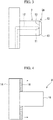
- FIG. 1 is a schematic configuration view of a molding tool 1 for molding a plastic container.
- the molding tool 1 shown in FIG. 1 includes a stationary mold 2 and a columnar mandrel 3 used as a mold core.
- the mandrel 3 is movable forward and backward with respect to the stationary mold 2.
- the mandrel 3 is mounted on the stationary mold 2 in a state where a laminated cylindrical element 4 that is an example of a thin cylindrical element is attached to the external surface (outer peripheral surface) of the mandrel 3 in a manner covering the mandrel 3 and a circular film 5 is made to abut against the tip of the mandrel 3.
- the mandrel 3 is formed in a columnar shape with a constant cross-sectional shape (a cross-section in a direction orthogonal to the longitudinal direction) from the base end side to a part short of the tip portion (part excluding a chamfered portion 13 to be described below). That is, the mandrel 3 is formed in a rod-like body with a constant outer circumferential length in the interval from the base end side to the part short of the tip portion.
- the laminated cylindrical element 4 is formed using a plastic laminate film as a material.
- the laminated cylindrical element 4 is formed in a cylindrical body with a constant cross-sectional shape (a cross-section in the direction orthogonal to the longitudinal direction) in order to form a tubular (cylindrical) trunk portion of a plastic container to be molded. That is, the laminated cylindrical element 4 is formed in a cylindrical shape in which its cross-sectional shape is a circular shape with a constant diameter, and has a constant inner circumferential length. Additionally, the circular film 5 forms a portion of the bottom of the plastic container. Moreover, although the tip portion of the mandrel 3 has a tapered shape, the tip portion will be described below in detail.
- the stationary mold 2 is formed with a space corresponding to the shape of a plastic container to be molded.
- a molding space 6 for forming a disk-shaped bottom of the plastic container is formed between the tip of the mandrel 3 and the stationary mold 2 in a state where the mandrel 3 is mounted on the stationary mold 2.
- an annular molding space 7 surrounding the external surface (outer peripheral surface) of the laminated cylindrical element 4 is formed between a base-side lateral face (base-side outer peripheral surface) of the mandrel 3 and the stationary mold 2.
- the molding space 6 and the molding space 7 that are cavities communicate with a runner 8 (channel) for filling them with melting resin provided in the stationary mold 2. Thereby, melting resin flows to the molding space 6 and the molding space 7.
- the laminated cylindrical element 4 attached to the mandrel 3 in a manner covering the mandrel 3 will be described in detail.
- the laminated cylindrical element 4 is a cylindrical body with both end openings, which is formed by overlapping and joining the side ends of a plastic laminate film that is a material that is cut in a rectangular shape.
- the laminated cylindrical element 4 may be a cylindrical body with both end openings, which is formed by butting and joining the side ends of a material, or may be a cylindrical body with both end openings, which is formed by overlapping side ends and then joining the side ends with an adhesive (sticky) tape from the inside.
- the plastic laminate film that is a material of the laminated cylindrical element 4 if a moisture-proof property or a gas barrier property is taken into consideration, a material obtained by laminating a polyethylene film with a thickness of 70 microns, a polyester film with a thickness of 12 microns, an aluminum foil with a thickness of 12 microns as a barrier materials, and a polyethylene film with a thickness of 70 microns is suitable. Additionally, the plastic laminate film may be a material obtained by laminating cast polypropylene with a thickness of 70 microns, a polyester film with a thickness of 12 microns, an aluminum foil with a thickness of 12 microns, and cast polypropylene with a thickness of 70 microns.
- the plastic laminate film may be a material obtained by laminating cast polypropylene with a thickness of 70 microns, a polyester film with a thickness of 12 microns, and cast polypropylene with a thickness of 70 microns.
- metallic foils such as an aluminum foil
- a material obtained by vapor-depositing metals such as aluminum or magnesium
- a material obtained by vapor-depositing metal oxides such as aluminum oxide or silicon oxide
- a coating film or the like formed by coating barrier films, such as polyvinyl alcohol or ethylene-vinylalcohol copolymer system, or barrier materials, such as polyvinylidene chloride, on a plastic film can be used.
- a laminated cylindrical element 4 made of a plastic laminate film as a laminate material is used in the present embodiment.
- a cylindrical element made of a material obtained by laminating plastics or an aluminum foil on paper or a unilaminate film-like material may be used. That is, the cylindrical element may be a film-like material made of a material having elasticity.
- a plastic container to be molded using the molding tool 1 is a bottomed cylindrical container, and a plastic container 20 molded in the molding tool 1 is shown in FIG. 2 .
- the plastic container 20 includes a trunk portion 21 molded in a cylindrical shape by the laminated cylindrical element 4, an upper molded portion 22 molded integrally with one end of the trunk portion 21, and a lower molded portion 23 molded integrally with the other end of the trunk portion 21.
- the upper molded portion 22 is an annular molded body, and is provided on the outer peripheral surface of the one end of the trunk portion 21.
- the upper molded portion 22 is a part formed by the molding space 7.
- the lower molded portion 23 is a disk-shaped molded body, and is provided so as to block the other end of the trunk portion 21.
- the lower molded portion 23 is a part formed by the molding space 6, and is combined integrally with the circular film 5.
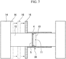
- the outer peripheral surface of a tip portion 3A of the mandrel 3 is formed with a groove portion 10 running in the circumferential direction thereof, and the groove portion 10 is formed with an ejection hole (gas ejection hole) 11 to eject air.
- the ejection hole 11 communicates with an air communication passage 12 formed inside the mandrel 3, and is capable of ejecting the air pumped from the air communication passage 12 to the outside.
- gases other than air may be ejected from the ejection hole 11, for example, inert gas (argon gas or the like) may be ejected.
- the tip portion 3A of the mandrel 3 is formed with the chamfered portion 13 that is an inducing portion for facilitating pressing the laminated cylindrical element 4, and thus the tip portion 3A of the mandrel 3 has a tapered shape.
- the external diameter of the portion excluding the chamfered portion 13 in the mandrel 3 is set to be greater than the internal diameter of the laminated cylindrical element 4 before the attaching and covering. That is, the outer circumferential length of the portion excluding the chamfered portion 13 in the mandrel 3 is set to be greater than the inner circumferential length of the laminated cylindrical element 4 before the attaching and covering.
- the external diameter on the tip side of the chamfered portion 13 is set to be less than the internal diameter of the laminated cylindrical element 4 before the attaching and covering. Therefore, the laminated cylindrical element 4 can be easily pressed and fitted onto the chamfered portion 13.
- the laminated cylindrical element 4 is attached to the mandrel 3.
- the laminated cylindrical element 4 is attached to the mandrel 3 using a delivery jig 9 shown in FIG. 4 .
- the delivery jig 9, as shown in FIG. 4 includes a columnar delivery jig body 15 that protrudes from a plate-shaped base part 14 and a movable part 16 that is provided radially outside the delivery jig body 15 so as to be slidable in the axial direction (the direction shown by the arrow in the drawing) of the delivery jig body 15.
- the external diameter of the delivery jig body 15 is set so that the laminated cylindrical element 4 can be attached to the external surface of the delivery jig body 15.
- the laminated cylindrical element 4 is attached to the external surface of the delivery jig body 15 in a manner covering the delivery jig body 15.
- the laminated cylindrical element 4 is brought into a state where an end portion thereof protrudes slightly from the tip of the delivery jig body 15.
- the circular film 5 is beforehand fitted into the inside of the laminated cylindrical element 4 at the end portion thereof, and is brought into a state of abutting the tip of the delivery jig body 15.
- the tip of the delivery jig body 15 and the tip of the mandrel 3 are arranged so as to face each other.
- the tip of the delivery jig body 15 is brought close to the mandrel 3 so as to abut the tip of the mandrel 3, and the part of the laminated cylindrical element 4 that protrudes out from the delivery jig body 15 is pressed onto the tip portion 3A of the mandrel 3.
- the outer circumferential length of the mandrel 3 is set to be greater than or equal to the inner circumferential length of the laminated cylindrical element 4, pressing of the laminated cylindrical element 4 is easily permitted because the chamfered portion 13 is formed at the tip portion 3A of the mandrel 3. That is, the laminated cylindrical element 4 is easily fitted to the tip portion 3A.
- the ejection hole 11 is formed in the groove portion 10, air can be efficiently blown into between the mandrel 3 and the laminated cylindrical element 4. That is, since the groove portion 10 is formed over the whole circumference of the tip portion 3A, air can be blown into between the mandrel 3 and the laminated cylindrical element 4 over the whole circumference.
- the ejection hole 11 may be formed in the outer peripheral surface of the mandrel 3 without forming the groove portion 10. In this case, in order to blow air into between the mandrel 3 and the laminated cylindrical element 4 over the whole circumference, it is preferable to form a plurality of ejection holes 11 in the circumferential direction of the mandrel 3.
- the laminated cylindrical element 4 pushed by the pressure of the ejected air expands radially outward. Therefore, the internal diameter of the laminated cylindrical element 4 becomes slightly greater than the external diameter of the portion excluding the chamfered portion 13 in the mandrel 3. Hence, it is possible to easily move the laminated cylindrical element 4 in the axial direction of the mandrel 3.
- the movable part 16 of the delivery jig 9 is moved in the axial direction (toward the tip side of the delivery jig body 15, the direction shown by the arrow in the drawing) of the delivery jig body 15 while ejecting air from the ejection hole 11.
- the movable part 16 abuts the laminated cylindrical element 4, and the laminated cylindrical element 4 is guided so as to be attached to the mandrel 3 in accordance with moving the movable part 16 forward.
- the circular film 5 slides relatively inside the laminated cylindrical element 4 as the movable part 16 moves the laminated cylindrical element 4.
- the movable part 16 moves the laminated cylindrical element 4 by a predetermined distance, to cause the laminated cylindrical element 4 to reach the base end part of the mandrel 3. If the ejecting of air from the ejection hole 11 is stopped, the pressure of the air that has expanded the laminated cylindrical element 4 disappears, and thus, the laminated cylindrical element 4 is restored to its internal diameter before the expansion.
- the external diameter of the mandrel 3 is set to be greater than the internal diameter before the expansion of the laminated cylindrical element 4, and the laminated cylindrical element 4 is attached to the outer peripheral surface of the mandrel 3 in a manner covering the mandrel 3 without a gap.
- the laminated cylindrical element 4 is attached to the overall mandrel 3 in a manner covering the mandrel 3 (the state shown in FIG.1 ), and thereby attachment of the laminated cylindrical element 4 to the mandrel 3 is completed.
- the attachment of the laminated cylindrical element 4 to the mandrel 3 is made in this way.
- the mandrel 3 is mounted on the stationary mold 2, and a synthetic resin material is injected into the molding space 6 and the molding space 7 in a molten state through the runner 8 from a gate (synthetic resin supply portion) provided in the stationary mold 2 by insertion injection molding means.
- a gate synthetic resin supply portion
- the synthetic resin material hardens, the upper molded portion 22 and the lower molded portion 23 of the plastic container 20 shown in FIG. 2 are molded.
- the synthetic resin material injected by the insertion injection molding means and the circular film 5 are integrated to mold the lower molded portion 23.
- the lower molded portion 23 may be formed only using the insertion injection molding means without using the circular film 5.
- removal (extraction) of the plastic container from the mold after molding can also be easily performed if air is ejected from the ejection hole 11 of the mandrel 3 after molding.
- the laminated cylindrical element 4 is attached to the external surface of the mandrel 3 in a manner covering the mandrel 3 by pressing the laminated cylindrical element 4 onto the tip portion 3A of the mandrel 3, and guiding the laminated cylindrical element 4 to the base end side of the mandrel 3 while ejecting air into between the mandrel 3 and the laminated cylindrical element 4.
- the cylinder-shaped laminated cylindrical element 4 with no taper, in which its inner circumferential length is set less than or equal to the outer circumferential length of the mandrel 3, can be easily attached to the mandrel 3.
- the laminated cylindrical element 4 can be produced by cutting a film-like material, which is formed in a long cylindrical body with a constant diameter, with predetermined dimensions. As a result, the manufacturing costs of the plastic container can be reduced, and the manufacturing efficiency thereof can be improved.
- the laminated cylindrical element 4 in which its inner circumferential length is set less than or equal to the outer circumferential length of the mandrel 3, can be used without requiring to enlarge the laminated cylindrical element 4 with respect to the mandrel 3, occurrence of wrinkles or the like can be suppressed and the quality of the cylindrical container can also be maintained.
- the present embodiment is different from the first embodiment in terms of the shape of the mandrel that is a mold core.
- parts common to those of the first embodiment will be designated by the same reference numerals, descriptions thereof will be omitted, and mainly differences will be described.
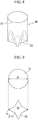
- a mandrel 30 of the present embodiment is shown in FIG. 8 .
- the upper side in the drawing is defined as the base end side of the mandrel 30, and the lower side in the drawing is defined as the tip side of the mandrel 30.
- the mandrel 30 of the present embodiment is a rod-like body in which its cross-sectional shape (cross-section in the direction orthogonal to the longitudinal direction) from a base end part 31 to a tip portion 32 is not constant, but the outer circumferential length thereof at the interval from the base end part 31 to the tip portion 32 is set constant.
- FIG. 9 A circular cross-section of the base end part 31 and a polygonal cross-section of the tip portion 32 in the mandrel 30 are shown in FIG. 9 .
- the cross-section of the tip portion 32 is octagonal, and the lengths of all sides thereof are the same.
- symbol A represents the length of one side of the tip portion 32
- symbol D1 represents the diameter (external diameter) of the base end part 31
- symbol D2 represents the maximum external diameter of the tip portion 32.
- the outer circumferential length from the base end part 31 to the tip portion 32 in the mandrel 30 is constant, with reference to FIG. 9 .
- the outer circumferential length (8xA) of the tip portion 32 is equal to the outer circumferential length ( ⁇ D1) of the base end part 31.
- the cross-section located between the base end part 31 and the tip portion 32 is also set to have an outer circumferential length equal to those of the circular cross-section of the base end part 31 and the polygonal cross-section of the tip portion 32.
- the external diameter D1 of the base end part 31 is set to be the maximum diameter in the whole longitudinal region of the mandrel 30 in consideration of ease of removal from the mold.
- the mandrel 30 is formed so that a part with a larger external diameter than the external diameter D1 of the base end part 31 is not present between the base end part 31 and the tip portion 32.
- the maximum external diameter D2 of the tip portion 32 is equal to the external diameter D1 of the base end part 31.
- the external diameter is the distance between opposed locations that are connected by a straight line passing through the central point of the mandrel 30 in the cross-section of the mandrel 30.
- the maximum external diameter of a cross-section located on the tip side may be set to be less than or equal to the maximum external diameter of a cross-section located on the base end side.
- the tip portion 32 of a mandrel 30 is formed with a chamfered portion 33, groove portion 34, and ejection hole 35, similar to those of the first embodiment.
- the laminated cylindrical element 4 is pressed onto the tip portion 32 of the mandrel 30 from the chamfered portion 33 side, and the laminated cylindrical element 4 is guided toward the base end part 31 of the mandrel 30 while ejecting air into between the mandrel 30 and the laminated cylindrical element 4 from the ejection hole 35.
- the plastic container 40 includes a trunk portion 41 molded in a cylindrical shape by the laminated cylindrical element 4, an upper molded portion 42 molded integrally with one end of the trunk portion 41, and a lower molded portion 43 molded integrally with the other end of the trunk portion 41.
- the upper molded portion 42 is an annular molded body, and is provided on the outer peripheral surface of the one end of the trunk portion 41.
- the lower molded portion 43 is provided so as to close the other end of the trunk portion 41, and has a polygonal shape corresponding to the shape of the tip portion 32 of the mandrel 30.
- the manufacturing costs of the plastic container can be reduced, the manufacturing efficiency thereof can be improved, and the quality of the cylindrical container can also be maintained. Additionally, a plastic container with a shape having rich variations can also be produced.
- the chamfered portion 13 formed at the tip portion 3A of the mandrel 3 is formed by so-called C-chamfering (its cross-sectional shape at a plane including the central axis of the mandrel 3 becomes a straight line).
- C-chamfering its cross-sectional shape at a plane including the central axis of the mandrel 3 becomes a straight line.
- arcuate chamfering may be performed. In such an arcuate chamfered portion, the cross-sectional shape at a plane including the central axis of the mandrel 3 becomes an arc.
- a separate body core having an external diameter less than the external diameter of the mandrel 3 may be attached to the tip portion 3A of the mandrel 3, without performing chamfering.
- the external diameter of the separate body core is set to be less than the internal diameter of the laminated cylindrical element 4 before the attaching and covering.
- the plastic container 20 is cylindrical and the laminated cylindrical element 4 is also cylindrical has been described in the first embodiment.
- the present invention can also be applied to a case where the trunk portion of the plastic container is rectangular in cross-sectional view.
- the laminated cylindrical element 4 is attached to the mandrel 3, 30 using the delivery jig 9 .
- the configurations of the delivery jig 9 may be other aspects, for example, the cross-sectional shape of the delivery jig body 15 may not be constant in the longitudinal direction.
- the laminated cylindrical element 4 may be manually attached to the mandrel 3, 30.
- the cylindrical element made of resin is attached to the mold core.
- Example 1 specific dimensions of the mandrel 3 and the laminated cylindrical element 4 described in the first embodiment were set, the laminated cylindrical element 4 was attached to the mandrel 3, and molding was performed.
- a member having a diameter of 55.66 mm and an outer circumferential length of 174.86 mm was used.
- the laminated cylindrical element 4 a member having a diameter of 54 mm and an outer circumferential length of 169.64 mm and that is small by 3.07% ((55.66-54)/54) with respect to the diameter of the mandrel 3 and is small by 3.07% ((174.86-169.64)/169.64) with respect to the outer circumferential length of the mandrel 3.
- a member including high-density polyethylene may also be referred to as "HDPE"; 100 ⁇ m in thickness), an adhesive, PET (12 ⁇ m in thickness), an adhesive, an aluminum foil (12 ⁇ m in thickness), an adhesive, and HDPE (120 ⁇ m in thickness) was used.
- HDPE high-density polyethylene
- the laminated cylindrical element 4 is easily attached to the mandrel 3 by pressing the laminated cylindrical element 4 having diameter and inner circumferential length that are less than those of the mandrel 3 onto the tip of the mandrel 3, and then guiding the laminated cylindrical element 4 to the base end side of the mandrel 3 while ejecting air. It was possible to confirm that a container with favorable appearance and functionality is also obtained without generation of wrinkles or the like in the container after molding.
- Example 2 Even in Example 2, specific dimensions of the mandrel 3 and the laminated cylindrical element 4 described in the first embodiment were set, the laminated cylindrical element 4 was attached to the mandrel 3, and molding was performed.
- a member having a diameter of 34.14 mm and an outer circumferential length of 107.25 mm was used.
- the laminated cylindrical element 4 a member that has a diameter of 33.74 mm and an outer circumferential length of 106.00 mm and that is small by 1.19% ((34.14-33.74)/33.74) with respect to the diameter of the mandrel 3 and is small by 1.18% ((107.25-106.00)/106.00) with respect to the outer circumferential length of the mandrel 3.
- the material of the laminated cylindrical element 4 a member including HDPE (50 ⁇ m in thickness), an adhesive, PET (12 ⁇ m in thickness), an adhesive, aluminum oxide vapor deposition (12 ⁇ m in thickness), an adhesive, and HDPE (120 ⁇ m in thickness) was used.
- the laminated cylindrical element 4 is easily attached to the mandrel 3 by guiding the laminated cylindrical element 4 having diameter and inner circumferential length that are less than those of the mandrel 3 to the base end side of the mandrel 3 while ejecting air. It was able to confirm that a container with favorable appearance and functionality was also obtained without the generation of wrinkles or the like in the container after molding.
Landscapes
- Engineering & Computer Science (AREA)
- Mechanical Engineering (AREA)
- Manufacturing & Machinery (AREA)
- Robotics (AREA)
- Moulds For Moulding Plastics Or The Like (AREA)
- Lining Or Joining Of Plastics Or The Like (AREA)
- Tubes (AREA)
- Chemical Vapour Deposition (AREA)
- Blow-Moulding Or Thermoforming Of Plastics Or The Like (AREA)
- Measuring Oxygen Concentration In Cells (AREA)
Priority Applications (1)
| Application Number | Priority Date | Filing Date | Title |
|---|---|---|---|
| PL11756300T PL2548709T3 (pl) | 2010-03-16 | 2011-03-15 | Sposób do produkcji pojemnika walcowego |
Applications Claiming Priority (2)
| Application Number | Priority Date | Filing Date | Title |
|---|---|---|---|
| JP2010059323A JP5538008B2 (ja) | 2010-03-16 | 2010-03-16 | 金型コアに対する薄肉筒状部材の取付方法、筒状容器の製造方法及び金型コア |
| PCT/JP2011/056066 WO2011115115A1 (ja) | 2010-03-16 | 2011-03-15 | 金型コアに対する薄肉筒状部材の取付方法、筒状容器の製造方法及び金型コア |
Publications (3)
| Publication Number | Publication Date |
|---|---|
| EP2548709A1 EP2548709A1 (en) | 2013-01-23 |
| EP2548709A4 EP2548709A4 (en) | 2016-02-17 |
| EP2548709B1 true EP2548709B1 (en) | 2017-12-06 |
Family
ID=44649199
Family Applications (1)
| Application Number | Title | Priority Date | Filing Date |
|---|---|---|---|
| EP11756300.7A Not-in-force EP2548709B1 (en) | 2010-03-16 | 2011-03-15 | Process for producing cylindrical container |
Country Status (8)
| Country | Link |
|---|---|
| US (2) | US20130106016A1 (pl) |
| EP (1) | EP2548709B1 (pl) |
| JP (1) | JP5538008B2 (pl) |
| CN (1) | CN102892562B (pl) |
| BR (1) | BR112012023145A2 (pl) |
| PL (1) | PL2548709T3 (pl) |
| RU (1) | RU2537598C2 (pl) |
| WO (1) | WO2011115115A1 (pl) |
Families Citing this family (7)
| Publication number | Priority date | Publication date | Assignee | Title |
|---|---|---|---|---|
| JP5818665B2 (ja) * | 2011-12-08 | 2015-11-18 | 東罐興業株式会社 | マンドレルおよび排出方法 |
| CN104527063B (zh) * | 2014-12-12 | 2016-08-24 | 江苏沃得植保机械有限公司 | 弹性手把安装在操纵杆端头的专用工装及方法 |
| CN105014886B (zh) * | 2015-07-10 | 2017-07-07 | 河南科技大学 | 水壶模具的凸模组件 |
| ES2698549T3 (es) | 2016-07-01 | 2019-02-05 | Sulzer Mixpac Ag | Cartucho, núcleo, molde y método de fabricación de un cartucho |
| JP7325738B2 (ja) * | 2019-10-15 | 2023-08-15 | 株式会社ポリマーシステムズ | 軟質容器の鍔形成装置及び方法 |
| CN112476956B (zh) * | 2020-11-09 | 2022-05-10 | 厦门水怡宝环保科技有限公司 | 一种杀菌装置、内置氟反射膜的组件及其成型方法 |
| JP2025007172A (ja) | 2023-06-30 | 2025-01-17 | 株式会社細川洋行 | 容器の製造方法、金型及び容器 |
Family Cites Families (15)
| Publication number | Priority date | Publication date | Assignee | Title |
|---|---|---|---|---|
| US1322843A (en) * | 1916-10-10 | 1919-11-25 | Anchor Cap & Closure Corp | Method for making rubber rings and the like. |
| DE1778916A1 (de) * | 1968-06-20 | 1971-08-05 | Phoenix Gummiwerke Ag | Dorn zum Herstellen von Kraftstoffschlaeuchen |
| US3900941A (en) * | 1974-02-08 | 1975-08-26 | Dayco Corp | Apparatus for and method of installing an expandible sleeve |
| US4215459A (en) * | 1978-11-09 | 1980-08-05 | The Goodyear Tire & Rubber Company | Method of removing hose from a mandrel and a mandrel adapted to the method |
| JPS60131223A (ja) * | 1983-12-21 | 1985-07-12 | Fuji Heavy Ind Ltd | 熱可塑性ホ−スの拡径方法 |
| US5127818A (en) * | 1990-10-10 | 1992-07-07 | Davidson Textron Inc. | Apparatus for extending contour gaskets |
| JP2976139B2 (ja) * | 1990-10-23 | 1999-11-10 | 大和製罐株式会社 | 多室容器の製造方法とその容器本体成形金型 |
| JPH0691692A (ja) * | 1992-09-11 | 1994-04-05 | Fuji Seal Kogyo Kk | 容器及びその製造方法 |
| US5415961A (en) * | 1992-09-29 | 1995-05-16 | Xerox Corporation | Flexible belt supported on rigid drum for electrophotographic imaging |
| JP3868510B2 (ja) * | 1993-12-08 | 2007-01-17 | 株式会社細川洋行 | 容器の製造方法 |
| JP3697083B2 (ja) * | 1998-09-29 | 2005-09-21 | 株式会社細川洋行 | プラスチック容器およびプラスチック容器の製造方法 |
| JP4275287B2 (ja) * | 2000-03-30 | 2009-06-10 | 株式会社細川洋行 | プラスチック容器 |
| JP2008007178A (ja) * | 2006-06-30 | 2008-01-17 | Yoshino Kogyosho Co Ltd | 複合チューブ容器 |
| CN201268078Y (zh) * | 2008-08-02 | 2009-07-08 | 俞建江 | 薄壁深腔类模具的压缩空气脱模系统 |
| JP5343282B2 (ja) | 2008-09-04 | 2013-11-13 | 学校法人立命館 | 2本鎖ヒドロゲル化剤 |
-
2010
- 2010-03-16 JP JP2010059323A patent/JP5538008B2/ja not_active Expired - Fee Related
-
2011
- 2011-03-15 PL PL11756300T patent/PL2548709T3/pl unknown
- 2011-03-15 CN CN201180018454.6A patent/CN102892562B/zh active Active
- 2011-03-15 RU RU2012143728/05A patent/RU2537598C2/ru active
- 2011-03-15 EP EP11756300.7A patent/EP2548709B1/en not_active Not-in-force
- 2011-03-15 WO PCT/JP2011/056066 patent/WO2011115115A1/ja not_active Ceased
- 2011-03-15 US US13/634,866 patent/US20130106016A1/en not_active Abandoned
- 2011-03-15 BR BR112012023145A patent/BR112012023145A2/pt not_active Application Discontinuation
-
2016
- 2016-04-01 US US15/089,202 patent/US10272604B2/en active Active
Non-Patent Citations (1)
| Title |
|---|
| None * |
Also Published As
| Publication number | Publication date |
|---|---|
| RU2537598C2 (ru) | 2015-01-10 |
| US20160214289A1 (en) | 2016-07-28 |
| US10272604B2 (en) | 2019-04-30 |
| EP2548709A4 (en) | 2016-02-17 |
| CN102892562A (zh) | 2013-01-23 |
| BR112012023145A2 (pt) | 2017-10-31 |
| RU2012143728A (ru) | 2014-04-27 |
| WO2011115115A1 (ja) | 2011-09-22 |
| CN102892562B (zh) | 2015-06-03 |
| EP2548709A1 (en) | 2013-01-23 |
| US20130106016A1 (en) | 2013-05-02 |
| JP2011189682A (ja) | 2011-09-29 |
| JP5538008B2 (ja) | 2014-07-02 |
| PL2548709T3 (pl) | 2018-05-30 |
Similar Documents
| Publication | Publication Date | Title |
|---|---|---|
| US10272604B2 (en) | Method for attaching thin cylindrical element to mold core | |
| US4709757A (en) | Method of injection molding and plastic part formed thereby | |
| WO2001026881A1 (en) | Method of producing laminated bottles having peelable inner layer | |
| CN102794902B (zh) | 具有安装部件的容器 | |
| US20130140731A1 (en) | Overmolding extruded profiles | |
| US10882240B2 (en) | Blow-molded lamination container and manufacturing method thereof | |
| CN1103273C (zh) | 粘合嵌件圆筒形制品和其成型方法及成型装置 | |
| JP6078257B2 (ja) | 二重容器、二重容器成形用プリフォーム、及び二重容器の製造方法 | |
| WO2015141056A1 (ja) | 分岐部付き中空部品の製造方法および製造装置 | |
| JP4420279B2 (ja) | 樹脂製等速ジョイント用ブーツの製造装置樹脂製等速ジョイント用ブーツの製造方法樹脂製等速ジョイント用ブーツ | |
| US11598482B2 (en) | High-pressure vessel | |
| JP2019081310A (ja) | 円筒成形品製造装置 | |
| AU2018267550B2 (en) | Soft container, soft container manufacturing apparatus, and soft container manufacturing method | |
| US11305308B2 (en) | Injection molding tool and method | |
| JP3678970B2 (ja) | ファイバードラムの筒状本体およびその製造方法 | |
| JP4060117B2 (ja) | インサートブロー成形方法及びその装置 | |
| WO2011152107A1 (ja) | ビード部材の製造装置及び製造方法 | |
| JP3682076B2 (ja) | 合成樹脂製の一端開口型筒状容器の製造方法 | |
| CN104494121A (zh) | 具有安装特征的容器 | |
| EP4219121B1 (en) | Resin sheet manufacturing method, extrusion head, and molded body manufacturing method | |
| JP5471753B2 (ja) | 燃料タンク製造方法及び燃料タンク | |
| EP4070930A1 (en) | Discharge member, accomodating container, production method for discharge member, mold for injection molding and discharge member with closing member | |
| KR20240076264A (ko) | 고압용기 성형장치 및 그에 의해 성형된 고압용기 | |
| JP2001261077A (ja) | シーラント押出し容器用プランジャーおよびシーラント押出し容器 | |
| JP6296021B2 (ja) | 押出装置 |
Legal Events
| Date | Code | Title | Description |
|---|---|---|---|
| PUAI | Public reference made under article 153(3) epc to a published international application that has entered the european phase |
Free format text: ORIGINAL CODE: 0009012 |
|
| 17P | Request for examination filed |
Effective date: 20120920 |
|
| AK | Designated contracting states |
Kind code of ref document: A1 Designated state(s): AL AT BE BG CH CY CZ DE DK EE ES FI FR GB GR HR HU IE IS IT LI LT LU LV MC MK MT NL NO PL PT RO RS SE SI SK SM TR |
|
| DAX | Request for extension of the european patent (deleted) | ||
| RA4 | Supplementary search report drawn up and despatched (corrected) |
Effective date: 20160115 |
|
| RIC1 | Information provided on ipc code assigned before grant |
Ipc: B29C 33/76 20060101ALI20160111BHEP Ipc: B29C 65/64 20060101ALI20160111BHEP Ipc: B29C 31/00 20060101ALI20160111BHEP Ipc: B29C 33/12 20060101AFI20160111BHEP Ipc: B29C 45/14 20060101ALI20160111BHEP |
|
| 17Q | First examination report despatched |
Effective date: 20161202 |
|
| GRAP | Despatch of communication of intention to grant a patent |
Free format text: ORIGINAL CODE: EPIDOSNIGR1 |
|
| INTG | Intention to grant announced |
Effective date: 20170613 |
|
| GRAS | Grant fee paid |
Free format text: ORIGINAL CODE: EPIDOSNIGR3 |
|
| GRAA | (expected) grant |
Free format text: ORIGINAL CODE: 0009210 |
|
| RAP1 | Party data changed (applicant data changed or rights of an application transferred) |
Owner name: THE JAPAN STEEL WORKS, LTD. Owner name: HOSOKAWA YOKO CO., LTD. |
|
| AK | Designated contracting states |
Kind code of ref document: B1 Designated state(s): AL AT BE BG CH CY CZ DE DK EE ES FI FR GB GR HR HU IE IS IT LI LT LU LV MC MK MT NL NO PL PT RO RS SE SI SK SM TR |
|
| REG | Reference to a national code |
Ref country code: GB Ref legal event code: FG4D |
|
| REG | Reference to a national code |
Ref country code: AT Ref legal event code: REF Ref document number: 951992 Country of ref document: AT Kind code of ref document: T Effective date: 20171215 Ref country code: CH Ref legal event code: EP |
|
| REG | Reference to a national code |
Ref country code: IE Ref legal event code: FG4D |
|
| REG | Reference to a national code |
Ref country code: DE Ref legal event code: R096 Ref document number: 602011043968 Country of ref document: DE |
|
| REG | Reference to a national code |
Ref country code: FR Ref legal event code: PLFP Year of fee payment: 8 |
|
| REG | Reference to a national code |
Ref country code: NL Ref legal event code: MP Effective date: 20171206 |
|
| REG | Reference to a national code |
Ref country code: LT Ref legal event code: MG4D |
|
| PG25 | Lapsed in a contracting state [announced via postgrant information from national office to epo] |
Ref country code: SE Free format text: LAPSE BECAUSE OF FAILURE TO SUBMIT A TRANSLATION OF THE DESCRIPTION OR TO PAY THE FEE WITHIN THE PRESCRIBED TIME-LIMIT Effective date: 20171206 Ref country code: ES Free format text: LAPSE BECAUSE OF FAILURE TO SUBMIT A TRANSLATION OF THE DESCRIPTION OR TO PAY THE FEE WITHIN THE PRESCRIBED TIME-LIMIT Effective date: 20171206 Ref country code: NO Free format text: LAPSE BECAUSE OF FAILURE TO SUBMIT A TRANSLATION OF THE DESCRIPTION OR TO PAY THE FEE WITHIN THE PRESCRIBED TIME-LIMIT Effective date: 20180306 Ref country code: FI Free format text: LAPSE BECAUSE OF FAILURE TO SUBMIT A TRANSLATION OF THE DESCRIPTION OR TO PAY THE FEE WITHIN THE PRESCRIBED TIME-LIMIT Effective date: 20171206 Ref country code: LT Free format text: LAPSE BECAUSE OF FAILURE TO SUBMIT A TRANSLATION OF THE DESCRIPTION OR TO PAY THE FEE WITHIN THE PRESCRIBED TIME-LIMIT Effective date: 20171206 |
|
| REG | Reference to a national code |
Ref country code: AT Ref legal event code: MK05 Ref document number: 951992 Country of ref document: AT Kind code of ref document: T Effective date: 20171206 |
|
| PG25 | Lapsed in a contracting state [announced via postgrant information from national office to epo] |
Ref country code: RS Free format text: LAPSE BECAUSE OF FAILURE TO SUBMIT A TRANSLATION OF THE DESCRIPTION OR TO PAY THE FEE WITHIN THE PRESCRIBED TIME-LIMIT Effective date: 20171206 Ref country code: HR Free format text: LAPSE BECAUSE OF FAILURE TO SUBMIT A TRANSLATION OF THE DESCRIPTION OR TO PAY THE FEE WITHIN THE PRESCRIBED TIME-LIMIT Effective date: 20171206 Ref country code: LV Free format text: LAPSE BECAUSE OF FAILURE TO SUBMIT A TRANSLATION OF THE DESCRIPTION OR TO PAY THE FEE WITHIN THE PRESCRIBED TIME-LIMIT Effective date: 20171206 Ref country code: GR Free format text: LAPSE BECAUSE OF FAILURE TO SUBMIT A TRANSLATION OF THE DESCRIPTION OR TO PAY THE FEE WITHIN THE PRESCRIBED TIME-LIMIT Effective date: 20180307 Ref country code: BG Free format text: LAPSE BECAUSE OF FAILURE TO SUBMIT A TRANSLATION OF THE DESCRIPTION OR TO PAY THE FEE WITHIN THE PRESCRIBED TIME-LIMIT Effective date: 20180306 |
|
| PG25 | Lapsed in a contracting state [announced via postgrant information from national office to epo] |
Ref country code: NL Free format text: LAPSE BECAUSE OF FAILURE TO SUBMIT A TRANSLATION OF THE DESCRIPTION OR TO PAY THE FEE WITHIN THE PRESCRIBED TIME-LIMIT Effective date: 20171206 |
|
| PG25 | Lapsed in a contracting state [announced via postgrant information from national office to epo] |
Ref country code: CZ Free format text: LAPSE BECAUSE OF FAILURE TO SUBMIT A TRANSLATION OF THE DESCRIPTION OR TO PAY THE FEE WITHIN THE PRESCRIBED TIME-LIMIT Effective date: 20171206 Ref country code: EE Free format text: LAPSE BECAUSE OF FAILURE TO SUBMIT A TRANSLATION OF THE DESCRIPTION OR TO PAY THE FEE WITHIN THE PRESCRIBED TIME-LIMIT Effective date: 20171206 Ref country code: SK Free format text: LAPSE BECAUSE OF FAILURE TO SUBMIT A TRANSLATION OF THE DESCRIPTION OR TO PAY THE FEE WITHIN THE PRESCRIBED TIME-LIMIT Effective date: 20171206 |
|
| PG25 | Lapsed in a contracting state [announced via postgrant information from national office to epo] |
Ref country code: IT Free format text: LAPSE BECAUSE OF FAILURE TO SUBMIT A TRANSLATION OF THE DESCRIPTION OR TO PAY THE FEE WITHIN THE PRESCRIBED TIME-LIMIT Effective date: 20171206 Ref country code: SM Free format text: LAPSE BECAUSE OF FAILURE TO SUBMIT A TRANSLATION OF THE DESCRIPTION OR TO PAY THE FEE WITHIN THE PRESCRIBED TIME-LIMIT Effective date: 20171206 Ref country code: RO Free format text: LAPSE BECAUSE OF FAILURE TO SUBMIT A TRANSLATION OF THE DESCRIPTION OR TO PAY THE FEE WITHIN THE PRESCRIBED TIME-LIMIT Effective date: 20171206 Ref country code: AT Free format text: LAPSE BECAUSE OF FAILURE TO SUBMIT A TRANSLATION OF THE DESCRIPTION OR TO PAY THE FEE WITHIN THE PRESCRIBED TIME-LIMIT Effective date: 20171206 |
|
| REG | Reference to a national code |
Ref country code: DE Ref legal event code: R097 Ref document number: 602011043968 Country of ref document: DE |
|
| PLBE | No opposition filed within time limit |
Free format text: ORIGINAL CODE: 0009261 |
|
| STAA | Information on the status of an ep patent application or granted ep patent |
Free format text: STATUS: NO OPPOSITION FILED WITHIN TIME LIMIT |
|
| REG | Reference to a national code |
Ref country code: CH Ref legal event code: PL |
|
| 26N | No opposition filed |
Effective date: 20180907 |
|
| PG25 | Lapsed in a contracting state [announced via postgrant information from national office to epo] |
Ref country code: MC Free format text: LAPSE BECAUSE OF FAILURE TO SUBMIT A TRANSLATION OF THE DESCRIPTION OR TO PAY THE FEE WITHIN THE PRESCRIBED TIME-LIMIT Effective date: 20171206 Ref country code: DK Free format text: LAPSE BECAUSE OF FAILURE TO SUBMIT A TRANSLATION OF THE DESCRIPTION OR TO PAY THE FEE WITHIN THE PRESCRIBED TIME-LIMIT Effective date: 20171206 Ref country code: SI Free format text: LAPSE BECAUSE OF FAILURE TO SUBMIT A TRANSLATION OF THE DESCRIPTION OR TO PAY THE FEE WITHIN THE PRESCRIBED TIME-LIMIT Effective date: 20171206 |
|
| REG | Reference to a national code |
Ref country code: BE Ref legal event code: MM Effective date: 20180331 |
|
| REG | Reference to a national code |
Ref country code: IE Ref legal event code: MM4A |
|
| PG25 | Lapsed in a contracting state [announced via postgrant information from national office to epo] |
Ref country code: LU Free format text: LAPSE BECAUSE OF NON-PAYMENT OF DUE FEES Effective date: 20180315 |
|
| PG25 | Lapsed in a contracting state [announced via postgrant information from national office to epo] |
Ref country code: IE Free format text: LAPSE BECAUSE OF NON-PAYMENT OF DUE FEES Effective date: 20180315 |
|
| PG25 | Lapsed in a contracting state [announced via postgrant information from national office to epo] |
Ref country code: CH Free format text: LAPSE BECAUSE OF NON-PAYMENT OF DUE FEES Effective date: 20180331 Ref country code: BE Free format text: LAPSE BECAUSE OF NON-PAYMENT OF DUE FEES Effective date: 20180331 Ref country code: LI Free format text: LAPSE BECAUSE OF NON-PAYMENT OF DUE FEES Effective date: 20180331 |
|
| PG25 | Lapsed in a contracting state [announced via postgrant information from national office to epo] |
Ref country code: MT Free format text: LAPSE BECAUSE OF NON-PAYMENT OF DUE FEES Effective date: 20180315 |
|
| PG25 | Lapsed in a contracting state [announced via postgrant information from national office to epo] |
Ref country code: TR Free format text: LAPSE BECAUSE OF FAILURE TO SUBMIT A TRANSLATION OF THE DESCRIPTION OR TO PAY THE FEE WITHIN THE PRESCRIBED TIME-LIMIT Effective date: 20171206 |
|
| PG25 | Lapsed in a contracting state [announced via postgrant information from national office to epo] |
Ref country code: PT Free format text: LAPSE BECAUSE OF FAILURE TO SUBMIT A TRANSLATION OF THE DESCRIPTION OR TO PAY THE FEE WITHIN THE PRESCRIBED TIME-LIMIT Effective date: 20171206 Ref country code: HU Free format text: LAPSE BECAUSE OF FAILURE TO SUBMIT A TRANSLATION OF THE DESCRIPTION OR TO PAY THE FEE WITHIN THE PRESCRIBED TIME-LIMIT; INVALID AB INITIO Effective date: 20110315 |
|
| PG25 | Lapsed in a contracting state [announced via postgrant information from national office to epo] |
Ref country code: MK Free format text: LAPSE BECAUSE OF NON-PAYMENT OF DUE FEES Effective date: 20171206 Ref country code: CY Free format text: LAPSE BECAUSE OF FAILURE TO SUBMIT A TRANSLATION OF THE DESCRIPTION OR TO PAY THE FEE WITHIN THE PRESCRIBED TIME-LIMIT Effective date: 20171206 |
|
| PG25 | Lapsed in a contracting state [announced via postgrant information from national office to epo] |
Ref country code: AL Free format text: LAPSE BECAUSE OF FAILURE TO SUBMIT A TRANSLATION OF THE DESCRIPTION OR TO PAY THE FEE WITHIN THE PRESCRIBED TIME-LIMIT Effective date: 20171206 Ref country code: IS Free format text: LAPSE BECAUSE OF FAILURE TO SUBMIT A TRANSLATION OF THE DESCRIPTION OR TO PAY THE FEE WITHIN THE PRESCRIBED TIME-LIMIT Effective date: 20180406 |
|
| PGFP | Annual fee paid to national office [announced via postgrant information from national office to epo] |
Ref country code: GB Payment date: 20220324 Year of fee payment: 12 Ref country code: DE Payment date: 20220322 Year of fee payment: 12 |
|
| PGFP | Annual fee paid to national office [announced via postgrant information from national office to epo] |
Ref country code: PL Payment date: 20220303 Year of fee payment: 12 Ref country code: FR Payment date: 20220323 Year of fee payment: 12 |
|
| REG | Reference to a national code |
Ref country code: DE Ref legal event code: R119 Ref document number: 602011043968 Country of ref document: DE |
|
| GBPC | Gb: european patent ceased through non-payment of renewal fee |
Effective date: 20230315 |
|
| PG25 | Lapsed in a contracting state [announced via postgrant information from national office to epo] |
Ref country code: GB Free format text: LAPSE BECAUSE OF NON-PAYMENT OF DUE FEES Effective date: 20230315 |
|
| PG25 | Lapsed in a contracting state [announced via postgrant information from national office to epo] |
Ref country code: GB Free format text: LAPSE BECAUSE OF NON-PAYMENT OF DUE FEES Effective date: 20230315 Ref country code: FR Free format text: LAPSE BECAUSE OF NON-PAYMENT OF DUE FEES Effective date: 20230331 Ref country code: DE Free format text: LAPSE BECAUSE OF NON-PAYMENT OF DUE FEES Effective date: 20231003 |
|
| PG25 | Lapsed in a contracting state [announced via postgrant information from national office to epo] |
Ref country code: PL Free format text: LAPSE BECAUSE OF NON-PAYMENT OF DUE FEES Effective date: 20230315 |
|
| PG25 | Lapsed in a contracting state [announced via postgrant information from national office to epo] |
Ref country code: PL Free format text: LAPSE BECAUSE OF NON-PAYMENT OF DUE FEES Effective date: 20230315 |