EP2548705B1 - Vorrichtung zum Entleeren eines Blutproduktbeutels - Google Patents
Vorrichtung zum Entleeren eines Blutproduktbeutels Download PDFInfo
- Publication number
- EP2548705B1 EP2548705B1 EP12382278.5A EP12382278A EP2548705B1 EP 2548705 B1 EP2548705 B1 EP 2548705B1 EP 12382278 A EP12382278 A EP 12382278A EP 2548705 B1 EP2548705 B1 EP 2548705B1
- Authority
- EP
- European Patent Office
- Prior art keywords
- bag
- product
- cutting
- rollers
- arms
- Prior art date
- Legal status (The legal status is an assumption and is not a legal conclusion. Google has not performed a legal analysis and makes no representation as to the accuracy of the status listed.)
- Active
Links
Images




Classifications
-
- B—PERFORMING OPERATIONS; TRANSPORTING
- B65—CONVEYING; PACKING; STORING; HANDLING THIN OR FILAMENTARY MATERIAL
- B65B—MACHINES, APPARATUS OR DEVICES FOR, OR METHODS OF, PACKAGING ARTICLES OR MATERIALS; UNPACKING
- B65B69/00—Unpacking of articles or materials, not otherwise provided for
-
- B—PERFORMING OPERATIONS; TRANSPORTING
- B25—HAND TOOLS; PORTABLE POWER-DRIVEN TOOLS; MANIPULATORS
- B25J—MANIPULATORS; CHAMBERS PROVIDED WITH MANIPULATION DEVICES
- B25J13/00—Controls for manipulators
- B25J13/08—Controls for manipulators by means of sensing devices, e.g. viewing or touching devices
- B25J13/086—Proximity sensors
-
- B—PERFORMING OPERATIONS; TRANSPORTING
- B25—HAND TOOLS; PORTABLE POWER-DRIVEN TOOLS; MANIPULATORS
- B25J—MANIPULATORS; CHAMBERS PROVIDED WITH MANIPULATION DEVICES
- B25J15/00—Gripping heads and other end effectors
- B25J15/02—Gripping heads and other end effectors servo-actuated
- B25J15/0206—Gripping heads and other end effectors servo-actuated comprising articulated grippers
-
- B—PERFORMING OPERATIONS; TRANSPORTING
- B25—HAND TOOLS; PORTABLE POWER-DRIVEN TOOLS; MANIPULATORS
- B25J—MANIPULATORS; CHAMBERS PROVIDED WITH MANIPULATION DEVICES
- B25J15/00—Gripping heads and other end effectors
- B25J15/08—Gripping heads and other end effectors having finger members
-
- B—PERFORMING OPERATIONS; TRANSPORTING
- B25—HAND TOOLS; PORTABLE POWER-DRIVEN TOOLS; MANIPULATORS
- B25J—MANIPULATORS; CHAMBERS PROVIDED WITH MANIPULATION DEVICES
- B25J9/00—Program-controlled manipulators
- B25J9/16—Program controls
-
- B—PERFORMING OPERATIONS; TRANSPORTING
- B65—CONVEYING; PACKING; STORING; HANDLING THIN OR FILAMENTARY MATERIAL
- B65B—MACHINES, APPARATUS OR DEVICES FOR, OR METHODS OF, PACKAGING ARTICLES OR MATERIALS; UNPACKING
- B65B69/00—Unpacking of articles or materials, not otherwise provided for
- B65B69/0033—Unpacking of articles or materials, not otherwise provided for by cutting
-
- B—PERFORMING OPERATIONS; TRANSPORTING
- B65—CONVEYING; PACKING; STORING; HANDLING THIN OR FILAMENTARY MATERIAL
- B65B—MACHINES, APPARATUS OR DEVICES FOR, OR METHODS OF, PACKAGING ARTICLES OR MATERIALS; UNPACKING
- B65B69/00—Unpacking of articles or materials, not otherwise provided for
- B65B69/005—Unpacking of articles or materials, not otherwise provided for by expelling contents, e.g. by squeezing the container
- B65B69/0058—Solid contents
Definitions
- the present invention relates to a device for removing a frozen product (preferably blood or a blood-derived product) from a flexible plastic container.
- a frozen product preferably blood or a blood-derived product
- the products stored in a particular embodiment of the present invention are usually of a biological nature and their sterility and the safety of the personnel who handle them must be maintained.
- Document US 5,829,634 discloses a device and method for unloading a frozen blood (plasma) product.
- This document discloses a device which includes a conveyor belt which carries the frozen plasma towards a cutting section. After making a transverse cut to the bag, the bag is moved to a toothed roller which grips the bag by the end opposite to the cut end and by applying pressure longitudinally from the gripping end to the opposite end the frozen product is expelled. Once the frozen product has been placed on the belt, means are used to collect the plasma and the bags are placed in a container for empty bags.
- Document WO 93/24371 discloses a method for unloading a container of frozen blood without having to partially thaw said blood. This method stems from the need to break the bond between the frozen plasma and the bag, presumably due to moisture which can form inside the bag when sterilisation by autoclave is carried out.
- This method consists in making a helical cut along the entire bag. Subsequently, the bag is passed between two rollers to eject the frozen plasma from this bag. This document also makes known that anything which exerts pressure the bag, first on one end and subsequently along the entire bag, can be used to extract the frozen contents.
- Document ES8603338 discloses a device for opening bags which have a protruding flap and a weak longitudinal line, i.e. a longitudinal line across the bag is weak or the bag is made so that it can be broken along this line.
- the emptying device for these bags includes a bag transporting station, which advances the bag to the stations for removal of the cover where jaws grip the protruding flap. These jaws exert a force on the bag causing it to break along the weak line, thereby expelling its contents.
- the present invention provides a device that allows, by independent means, containers of frozen products to be emptied correctly and reliably whilst maintaining the cleanliness and sterility of the product and ensuring lower product losses than in devices known in the art and increased productivity.
- US 5 829 634 A discloses a device according to the precharacterizing portion of claim 1.
- US 2010/206119 A discloses a grass seed sack end effector which includes a robotic arm with two groups of catching arms and an actuator modifying the distance separating the distal ends of the gripper arms in order to catch the bag by its lower surface.
- the catching arms are two substantially semi-ellipsoidal transversal section arms attached to a transporting device by means of an articulation, with the actuator being provided with means for rotating the said articulation.
- the transport device is a robotic arm.
- the robotic arm includes a stop which is placed in one of the longitudinal ends of the bag and between said clamping arms.
- This stop preferably, includes a proximity detector.
- the proximity detector may make a terminal to the track.
- the edge is situated above a receiving hopper of the product extracted by the extractor.
- the cutting device is a device for transversely cutting the bag.
- the cutting device is a toothed cutting device which generates a discontinuous cut in the bag preventing the contents from coming out of the bag by their own means and allowing the extracting device to break these discontinuities of the bag by pressure.
- the device includes a fixed inclined platform with lateral walls which constitute a track for centring and delivering the bag to the robotic arm.
- the device includes a conveyor belt to transport the bags to the conveyor device (for example, to the platform).
- the band is inclined. This will facilitate the cleaning of the device so that the plasma, which is thawed during the track of the bag, falls due to gravity. Therefore, it is sufficient to have water available in the upper part of the band to clean the thawed plasma during its track.
- the plasma extractor includes two rollers.
- the rollers are in contact and rotate in opposite directions, thus enhancing the grip on the bag by making it pass through them and exerting a longitudinal pressure along the entire bag.
- At least one roller is of non-slip material.
- drawings are appended by way of an explanatory but non-limiting example of an embodiment of the method and of the device for emptying a blood product bag according to the present invention.
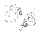
- a robotic arm - 1 - which includes an arm body - 11 - and a gripping device - 10 -. Also shown are an extraction device - 2 -, including a motor - 21 -, and a product extractor which, in this particular case, is two rollers - 22 - arranged so that they come into contact to exert pressure on a container (in this particular case a bag) when the bag is put through them. Also shown is a hopper - 23 - for the disposal of the product extracted from said bag.
- the embodiment shown in figure 1 seeks to transfer bags located in a reception area - 3 -, coming from a transport system, for example, a conveyor (not shown) to an extraction device - 2 - which minimises the dirt produced by the thawed plasma during the transporting procedure. As a result, it is appropriate to move the container from the conveyor belt to a remote device, such as the hopper - 23
- the extraction device in this particular case, includes two rollers - 22 - and a motor - 21 -. These rollers rotate in opposite directions so that a container (or a bag) placed at the junction of both rollers is driven towards the rollers and, in turn, a force is exerted from the content of the bag towards the outside of the rollers, i.e. towards the hopper - 23 -.
- the plastic bag - 5 - is absorbed in the opposite direction and delivered to a container - 24 -.
- one of the rollers is of metallic material and the other roller is of non-slip material.
- the gripping device - 1 - in the example includes two semi-ellipsoid arms - 101 -, - 102 - although in a particularly preferred model, they could be two "L" shaped arms.
- the arm - 101 - is attached to a projection - 103 - of the robotic arm (not shown) by means of a rotatable joint, i.e. an articulation - 1011 -.
- the rotation of this articulation - 1011 - defines whether the position of the gripping device is an active or a passive position.
- the articulation - 1021 - defines the position of the arm - 102 -.
- the term “active position” will be applied to the position in which the arm catches the container and the term “passive position” to the one in which the arm does not catch the container.
- an actuator (not shown) rotates the articulations - 1021 -, - 1011 - in opposite directions causing the arms - 101 -, - 102 - to rotate in opposite directions such that the gripping device opens, allowing the arm to approach a container.
- this model of the gripping device allows the container to be caught by its base; this detail is of significant importance since the containers, in a preferred model, contain frozen material which makes the container too slippery to be held by its lateral ends.
- the use of the arms - 101 -, - 102 - of the present invention provide an additional clamping of the container by keeping it resting on its base at the semi-ellipsoidal arms.
- the gripping device coupled to the body of the robotic arm - 11 - incorporates a stop - 104 -.
- the incorporation of the stop -104 - makes it possible for the device to detect the proximity of the surface on which the containers are situated by incorporating a proximity sensor at its distal end.
- the incorporation of the stop - 104 - prevents the bag from moving longitudinally on the arms thus preventing biohazardous material from falling.
- this stop - 104 - is used also as a pushing device once the bag is placed between the rollers.
- the location of this stop may be variable depending on the particularities of each application.
- the said stop is placed in the gripping device and not in the arm body.
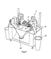
- a reception area can also be seen - 3 - from where the robotic arm - 1 - picks up the bag - 5 -.
- the reception area is a fixed platform or an inclined tray with a stop - 31 - and side walls with openings - 32 - which favour the passage of the fingers of the arms - 101 -, - 102 - of the claw of this arm.
- the tray is thus a centring track and delivers the bags to the robotic arm - 1 -.
- the device includes a cutting device - 4 - which includes a fixed blade - 41 - with an upper edge - 42 -.
- the fixed blade - 41 - is located above the hopper - 23- for collecting the product, in such a way that any drop which may escape from the bag - 5 - during the cutting process would fall into the hopper - 23 - together with the frozen material extracted from the bag - 5 - by the rollers - 22 -.
- the cutting device - 4 - is in an intermediate position between the reception area - 3 - and the extractor - 2 -. Specifically, the blade - 41 -, which is fixed, is in the path which the bag - 5 - follows, just below it.
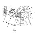
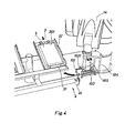
- Figures 4 to 7 show the process of collection, cutting and extraction of a bag - 5 - .
- the robotic arm picks up the bag - 5 - and the upper edge - 42 - of the blade - 41 - tears the bag.
- the upper edge - 42 - it is not even necessary for the upper edge - 42 - to be very sharp, since to meet the objective it is not necessary to make an effective cut of the bag.
- a partial tear is sufficient to generate a preferred area of opening, when the rollers -22- exert pressure on the bag.
- the embodiment of Figures 7 to 12 includes a conveyor on which completely sealed frozen plasma bags are arranged.
- This conveyor belt carries the bags to a cutting device.
- the cutting device makes a cut, either continuous (conventional blade) or discontinuous (serrated blade) in one of the ends of the bag.
- the bag is carried, by means of the mechanical robotic arm - 1 -, to an extraction device which extracts the frozen product from the bag, and this frozen product is collected in a hopper - 23 - designed for that purpose.
- the conveyor can be inclined at an angle.
- water or a suitable liquid for cleaning
- the cutting device may be a continuous or discontinuous cutting device, in one preferred model the cutting is performed discontinuously, such that, when the bag is available in the extractor this exerts a sufficient force on the bag to complete breaking it and ejecting the contents.
- the robotic arm - 1 - can be seen which includes an arm body - 11 - and a gripping device - 10 -.
- the extraction device - 2 - is also shown and includes a motor - 21 -and an extractor which, in this particular case, is two rollers - 22 - arranged so that they come into contact to exert pressure on a container (in this particular case a bag) when the bag is placed across them. Additionally, a hopper - 23 - is shown for the disposal of the product extracted from this bag.
- the embodiment shown in Figure 7 can be intended for transferring bags originating from a transport system, for example, a conveyor (not shown) to an extraction device - 2 - which minimises the dirt produced by the thawed plasma during the transport process. Therefore, it is appropriate to move the container from the conveyor belt to a remote device, such as the hopper - 23 -.
- a transport system for example, a conveyor (not shown) to an extraction device - 2 - which minimises the dirt produced by the thawed plasma during the transport process. Therefore, it is appropriate to move the container from the conveyor belt to a remote device, such as the hopper - 23 -.
- the extraction device in this particular case, includes two rollers - 22 - and a motor - 21 -. These rollers rotate in opposite directions such that a container (or bag) placed at the junction of the two rollers is driven into the rollers and, in turn, a force is exerted from the inside of the bag towards the outside of the rollers, i.e. towards the hopper - 23 -.
- one of the rollers is of metallic material and the other roller is of a non-slip material.
- Figure 8 shows a gripping device - 10 - according to the present invention.
- the embodiment of Figure 2 includes two semi-ellipsoidal arms - 101 -, - 102 -, although in a particularly preferred model, they could be two "L" shaped arms.
- the arm - 101 - is attached to a projection - 103 - of the robotic arm (not shown) by means of a rotatable joint, i.e. an articulation - 1011 -.
- the rotation of this articulation - 1011 - defines whether the gripping device is in an active or a passive position.
- the articulation - 1021 - defines the position of the arm - 102 -.
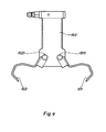
- Figure 9 shows the embodiment of the gripping device of Figure 2 in a passive position.
- an actuator (not shown) rotates the articulations - 1021 -, - 1011 - in opposite directions causing the arms - 101 -, - 102 - to rotate in opposite directions such that the gripping device opens, allowing the arm to approach a container.
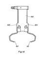
- Figure 10 shows the embodiment of the gripping device of Figure 2 in an active position. It is to be noted that this model of the gripping device allows the container to be caught by its base; this detail is of significant importance in that the containers, in a preferred model, contain frozen material which makes the container too slippery to be held by its side ends.
- the use of the arms - 101 -, - 102 - of the present invention provides an additional clamping of the container so as to keep it resting on its base at the semi-ellipsoidal arms.
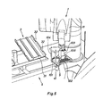
- Figures 11 and 12 show the gripping device coupled to the body of the robotic arm - 11 -, at which point the incorporation of a stop - 104 - can be seen.
- the incorporation of the stop - 104 - enables the device to detect the proximity of the surface on which the containers are located by incorporating a proximity sensor at its distal end.
- stop - 104 stops the bag moving longitudinally on the arms ,thus preventing biohazardous material from falling.
- this stop - 104 - is also used as a pushing device as long as the bag is between the rollers.
- the location of this stop may be variable depending on the particularities of each application. In a particularly preferred embodiment, this stop is placed in the gripping device and not in the body of the arm.
Landscapes
- Engineering & Computer Science (AREA)
- Mechanical Engineering (AREA)
- Robotics (AREA)
- Human Computer Interaction (AREA)
- Control And Other Processes For Unpacking Of Materials (AREA)
- External Artificial Organs (AREA)
Claims (17)
- Vorrichtung zum Leeren eines Behälters, welcher ein gefrorenes blutabgeleitetes Produkt enthält, beinhaltend:- einen Produktextraktor (22);- einen Trichter (23) zum Aufnehmen des Produkts;- eine Vorrichtung zum Transportieren des Behälters von einem Aufnahmebereich (3) zu dem Produktextraktor, (22)- eine Schneidevorrichtung (4), welche eine Schneidekante beinhaltet, welche in dem Weg von dem Behälter zwischen dem Aufnahmebereich (3) und dem Produktextraktor (22) platziert ist,dadurch gekennzeichnet, dass die Transportvorrichtung einen Roboterarm (1) mit einem Greifer beinhaltet, welcher seinerseits beinhaltet:- zwei Greifarme (101, 102), wobei jeder wenigstens ein entferntes Ende und ein nahes Ende definiert,
und- einen Auslöser,in welchem der Auslöser einen Mechanismus steuert, der die Distanz, welche die entfernten Enden von diesen Greiferarmen separiert, modifiziert, um den Behälter an seiner unteren Oberfläche zu greifen, und dass die Schneidevorrichtung (4) eine feste Klinge (41) ist. - Vorrichtung gemäß Anspruch 1, dadurch gekennzeichnet, dass die Schneidekante eine obere Schneidekante (42) ist, welche genau unter dem Weg von dem Behälter platziert ist.
- Vorrichtung gemäß Anspruch 1, dadurch gekennzeichnet, dass die Schneidekante über dem Trichter (23) platziert ist, um das Produkt aufzunehmen, welches durch den Extraktor extrahiert wird.
- Vorrichtung gemäß einem der Ansprüche 1 bis 3, dadurch gekennzeichnet, dass der Aufnahmebereich eine geneigte feste Plattform mit seitlichen Wänden beinhaltet, welche einen Pfad zum Zentrieren und Liefern von Behältern zu der Transportvorrichtung beinhaltet.
- Vorrichtung gemäß einem der Ansprüche 1 bis 4, dadurch gekennzeichnet, dass die Greifarme (101,102) zwei Arme mit einem im Wesentlichen halbelliptischen Querschnitt sind, welche mit dem Roboterarm (1) durch Mittel einer Verbindung verbunden sind.
- Vorrichtung gemäß Anspruch 5, dadurch gekennzeichnet, dass der Auslöser Mittel zum Drehen des Gelenks hat.
- Vorrichtung gemäß einem der Ansprüche 1 bis 6, dadurch gekennzeichnet, dass der Roboterarm eine Raste (104) beinhaltet, welche an einem von den längslaufenden Enden von dem Behälter, welcher das gefrorene Produkt beinhaltet, und zwischen den Greifarmen platziert ist.
- Vorrichtungsgemäß Anspruch 7, dadurch gekennzeichnet, dass die Raste (104) einen Nähedetektor beinhaltet.
- Vorrichtung gemäß einem der vorangehenden Ansprüche 1 bis 8, dadurch gekennzeichnet, dass die Schneidevorrichtung (4) eine Vorrichtung zum Querschneiden des Behälters ist.
- Vorrichtung gemäß einem der Ansprüche 1 bis 9, dadurch gekennzeichnet, dass sie ein Behälterförderband für den Transport zu der Transportvorrichtung beinhaltet.
- Vorrichtung gemäß Anspruch 10, dadurch gekennzeichnet, dass das Band geneigt ist
- Vorrichtung gemäß einem der Ansprüche 1 bis 11, dadurch gekennzeichnet, dass der Produktextraktor (22) zwei Rollen beinhaltet.
- Vorrichtung gemäß Anspruch 12, dadurch gekennzeichnet, dass die Rollen in Kontakt sind.
- Vorrichtung gemäß einem der Ansprüche 12 oder 13, dadurch gekennzeichnet, dass der Produktextraktor einen Motor (21) beinhaltet, welcher mit den Rollen verbunden ist, um diese zu drehen.
- Vorrichtung gemäß Anspruch 12, dadurch gekennzeichnet, dass die Rollen so verbunden sind, dass sie in entgegengesetzte Richtungen rotieren.
- Vorrichtung gemäß einem der Ansprüche 12 bis 15, dadurch gekennzeichnet, dass wenigstens eine Rolle aus einem rutschfesten Material gemacht ist.
- Vorrichtung gemäß Anspruch 1, dadurch gekennzeichnet, dass die Schneidevorrichtung (4) eine gezahnte Klinge ist.
Applications Claiming Priority (2)
| Application Number | Priority Date | Filing Date | Title |
|---|---|---|---|
| ES201131265A ES2370884B1 (es) | 2011-07-22 | 2011-07-22 | Método y dispositivo vaciador de bolsas de producto sanguíneo. |
| ES201131901A ES2377608B1 (es) | 2011-11-24 | 2011-11-24 | Dispositivo vaciador de bolsas de producto sanguíneo mejorado. |
Publications (2)
| Publication Number | Publication Date |
|---|---|
| EP2548705A1 EP2548705A1 (de) | 2013-01-23 |
| EP2548705B1 true EP2548705B1 (de) | 2015-07-08 |
Family
ID=46679226
Family Applications (1)
| Application Number | Title | Priority Date | Filing Date |
|---|---|---|---|
| EP12382278.5A Active EP2548705B1 (de) | 2011-07-22 | 2012-07-12 | Vorrichtung zum Entleeren eines Blutproduktbeutels |
Country Status (11)
| Country | Link |
|---|---|
| US (1) | US8690011B2 (de) |
| EP (1) | EP2548705B1 (de) |
| JP (1) | JP5996958B2 (de) |
| KR (1) | KR101913763B1 (de) |
| AR (1) | AR087265A1 (de) |
| AU (1) | AU2012204103B2 (de) |
| BR (1) | BR102012018226B1 (de) |
| CA (1) | CA2783521C (de) |
| ES (1) | ES2544723T3 (de) |
| MX (1) | MX2012008404A (de) |
| RU (1) | RU2602913C2 (de) |
Families Citing this family (16)
| Publication number | Priority date | Publication date | Assignee | Title |
|---|---|---|---|---|
| GB2512405B (en) * | 2013-03-28 | 2018-05-30 | D C Norris & Company Ltd | Bag emptying system |
| WO2014208019A1 (ja) * | 2013-06-28 | 2014-12-31 | パナソニックIpマネジメント株式会社 | メタノール生成装置、メタノールを生成する方法及びメタノール生成用電極 |
| US10055567B2 (en) | 2014-05-30 | 2018-08-21 | Apple Inc. | Proximity unlock and lock operations for electronic devices |
| CN105947333B (zh) * | 2014-07-25 | 2018-03-02 | 江苏鸿顺合纤科技有限公司 | 锦纶切片进料专用划袋器 |
| US10329042B2 (en) | 2015-03-20 | 2019-06-25 | Seiko Epson Corporation | Packing apparatus and packing method |
| US20170271089A1 (en) * | 2016-03-18 | 2017-09-21 | Kabushiki Kaisha Toshiba | Electrochemical reaction device |
| CN109204983A (zh) * | 2017-07-04 | 2019-01-15 | 衡阳鑫山机械设备制造有限公司 | 一种自动血、袋分离机 |
| EP3438010B1 (de) | 2017-07-31 | 2019-08-14 | Grifols Worldwide Operations Limited | Automatische vorrichtung zum entleeren von säcken von gefrorenem blutprodukt |
| US10695902B2 (en) | 2018-06-04 | 2020-06-30 | Express Scripts Strategic Development, Inc. | Pharmacy order processing system |
| US10865006B2 (en) * | 2018-06-04 | 2020-12-15 | Express Scripts Strategic Development, Inc. | Pharmacy order processing system workstations and related methods |
| CN108890622B (zh) * | 2018-07-23 | 2019-08-09 | 深圳市恒翼能科技有限公司 | 一种锂电池组合夹具装置 |
| JP7515485B2 (ja) | 2019-02-06 | 2024-07-12 | マレル・サーモン・アクティエセルスカブ | 蓋付き箱を開梱及び荷空けするためのシステム |
| KR102083025B1 (ko) * | 2019-10-10 | 2020-02-28 | 장인재 | 장류 비닐 포장지의 내용물 압착 배출장치 및 그 압착 배출장치를 이용한 내용물 압착 배출 방법 |
| CA3150983A1 (en) * | 2019-11-01 | 2021-05-06 | Phil SCHAAFSMA | Case unpacking system and method |
| CN115447954A (zh) * | 2022-09-23 | 2022-12-09 | 湖北鑫宝马弹簧有限公司 | 一种卡车离合器弹簧立定处理或负荷分选的自动上料设备 |
| CN115892656B (zh) * | 2022-12-05 | 2024-06-25 | 南京市普非森电气自动化科技有限责任公司 | 一种吨袋自动破袋机 |
Family Cites Families (16)
| Publication number | Priority date | Publication date | Assignee | Title |
|---|---|---|---|---|
| US4253458A (en) | 1979-03-08 | 1981-03-03 | Baxter Travenol Laboratories, Inc. | Method and apparatus for collecting blood plasma |
| US4340152A (en) * | 1980-08-08 | 1982-07-20 | Baxter Travenol Laboratories, Inc. | Method and apparatus for removing the contents of flexible or collapsible containers |
| EP0159792A3 (de) * | 1984-03-16 | 1986-11-20 | Tuta Laboratories (Australia) Pty Ltd. | Beutelreissmaschine |
| JPS6171302A (ja) * | 1984-09-14 | 1986-04-12 | Toshiba Corp | ロボットハンド用近接センサ装置 |
| GB8509670D0 (en) * | 1985-04-16 | 1985-05-22 | Tuskprime Ltd | Bag slitting & emptying machine |
| FR2639907B1 (fr) * | 1988-12-02 | 1991-06-14 | Sala Jaime Marti | Procede d'alimentation automatique d'une ligne d'embouteillage. ensemble et dispositif pour sa mise en oeuvr |
| WO1993024371A1 (en) | 1992-05-29 | 1993-12-09 | Baxter International Inc. | Removal of blood product from a container |
| JPH09286422A (ja) * | 1996-04-17 | 1997-11-04 | Imabayashi Tekkosho:Kk | 包装された加工肉の取り出し装置 |
| AT1650U1 (de) * | 1996-06-26 | 1997-09-25 | Immuno Ag | Verfahren und vorrichtung zum ausbringen eines tiefgefrorenen plasmaproduktes |
| US5870886A (en) * | 1997-02-03 | 1999-02-16 | The West Company, Incorporated | Transfer system for transferring objects into a barrier isolator |
| ES2245837B1 (es) | 2002-03-26 | 2007-07-16 | Grifols, S.A. | Pinza para la manipulacion de recipientes de plasma sanguineo. |
| ES2245836B1 (es) * | 2002-03-26 | 2006-10-01 | Grifols, S.A. | Procedimiento y aparato para el vaciado de recipientes de plasma sanguineo. |
| NL1023756C2 (nl) * | 2003-06-26 | 2004-12-28 | Logitec Plus B V | Scheidingsinrichting. |
| DE102006051513B3 (de) * | 2006-10-31 | 2007-08-16 | Hecht Anlagenbau Gmbh | Verfahren zum Betreiben einer Verpackungsentleerstation |
| US20100206119A1 (en) * | 2009-02-04 | 2010-08-19 | Columbia/Okura Llc | Grass seed bag end effector |
| DE102009056225B4 (de) * | 2009-11-28 | 2015-02-05 | Magurit Gefrierschneider Gmbh | Vorrichtung zum kontinuierlichen Öffnen und Leeren von Gefriergut enthaltenden Beuteln, insbesondere Blutplasmabeuteln |
-
2012
- 2012-07-09 RU RU2012128890/15A patent/RU2602913C2/ru active
- 2012-07-11 AU AU2012204103A patent/AU2012204103B2/en active Active
- 2012-07-12 ES ES12382278.5T patent/ES2544723T3/es active Active
- 2012-07-12 EP EP12382278.5A patent/EP2548705B1/de active Active
- 2012-07-18 US US13/551,738 patent/US8690011B2/en active Active
- 2012-07-19 MX MX2012008404A patent/MX2012008404A/es active IP Right Grant
- 2012-07-19 CA CA2783521A patent/CA2783521C/en active Active
- 2012-07-20 JP JP2012161377A patent/JP5996958B2/ja active Active
- 2012-07-20 KR KR1020120079616A patent/KR101913763B1/ko active Active
- 2012-07-20 AR ARP120102645A patent/AR087265A1/es active IP Right Grant
- 2012-07-23 BR BR102012018226-2A patent/BR102012018226B1/pt active IP Right Grant
Also Published As
| Publication number | Publication date |
|---|---|
| CA2783521A1 (en) | 2013-01-22 |
| BR102012018226B1 (pt) | 2021-05-11 |
| US8690011B2 (en) | 2014-04-08 |
| JP5996958B2 (ja) | 2016-09-21 |
| KR101913763B1 (ko) | 2018-10-31 |
| CA2783521C (en) | 2016-08-09 |
| KR20130012061A (ko) | 2013-01-31 |
| JP2013023287A (ja) | 2013-02-04 |
| ES2544723T3 (es) | 2015-09-03 |
| EP2548705A1 (de) | 2013-01-23 |
| US20130019993A1 (en) | 2013-01-24 |
| AU2012204103B2 (en) | 2014-02-13 |
| AR087265A1 (es) | 2014-03-12 |
| AU2012204103A1 (en) | 2013-02-07 |
| RU2602913C2 (ru) | 2016-11-20 |
| MX2012008404A (es) | 2013-01-24 |
| RU2012128890A (ru) | 2014-01-20 |
| BR102012018226A2 (pt) | 2015-07-21 |
Similar Documents
| Publication | Publication Date | Title |
|---|---|---|
| CA2783521C (en) | Device for emptying a blood product bag | |
| CN110248536B (zh) | 机器人收获系统 | |
| EP4404728B1 (de) | Roboter zum ernten von früchten und endeffektor dafür | |
| KR20240004722A (ko) | 과일과 식물을 자동으로 파지하고 절단하는 시스템 및 방법 | |
| KR101851304B1 (ko) | 양송이대 커팅장치 | |
| AU2011319872A1 (en) | Mechanical produce harvester | |
| NL2028330B1 (en) | End effector for robotic removal of a part of a crop and manufacturing method thereof | |
| CN207712446U (zh) | 智能拆箱机 | |
| WO2022271039A1 (en) | Method and apparatus for processing plastic liner bags | |
| CN114940295B (zh) | 并联气吹式血浆袋破袋方法 | |
| CN103959983B (zh) | 作物收割机 | |
| CN109677719A (zh) | 包装箱扎带自动去除装置及方法 | |
| GB2614401A (en) | Medical waste disposal and container washing system | |
| ES2377608B1 (es) | Dispositivo vaciador de bolsas de producto sanguíneo mejorado. | |
| JP2017030845A (ja) | 袋体の自動開封装置 | |
| ES2370884B1 (es) | Método y dispositivo vaciador de bolsas de producto sanguíneo. | |
| EP2390195B1 (de) | Entleerungsvorrichtung, insbesondere für verformbare Behälter | |
| CN109835558B (zh) | 一种包装箱扎带去除方法 | |
| CN114940294B (zh) | 血浆袋多路同步传输处理方法 | |
| CN220448359U (zh) | 一种原料破袋系统 | |
| NZ789708A (en) | Method and apparatus for processing plastic liner bags | |
| JPH0974865A (ja) | 野菜収穫機の外葉除去装置 | |
| JPH03124528A (ja) | 易溶融固形物の包装材からの取出し方法および装置 | |
| JP2010178752A (ja) | サトウキビ梢頭部飼料化システム | |
| WO2005022976A2 (en) | Food product harvesting methods and apparatus |
Legal Events
| Date | Code | Title | Description |
|---|---|---|---|
| PUAI | Public reference made under article 153(3) epc to a published international application that has entered the european phase |
Free format text: ORIGINAL CODE: 0009012 |
|
| AK | Designated contracting states |
Kind code of ref document: A1 Designated state(s): AL AT BE BG CH CY CZ DE DK EE ES FI FR GB GR HR HU IE IS IT LI LT LU LV MC MK MT NL NO PL PT RO RS SE SI SK SM TR |
|
| AX | Request for extension of the european patent |
Extension state: BA ME |
|
| 17P | Request for examination filed |
Effective date: 20130226 |
|
| 17Q | First examination report despatched |
Effective date: 20140508 |
|
| GRAP | Despatch of communication of intention to grant a patent |
Free format text: ORIGINAL CODE: EPIDOSNIGR1 |
|
| INTG | Intention to grant announced |
Effective date: 20150119 |
|
| GRAP | Despatch of communication of intention to grant a patent |
Free format text: ORIGINAL CODE: EPIDOSNIGR1 |
|
| INTG | Intention to grant announced |
Effective date: 20150415 |
|
| GRAS | Grant fee paid |
Free format text: ORIGINAL CODE: EPIDOSNIGR3 |
|
| GRAA | (expected) grant |
Free format text: ORIGINAL CODE: 0009210 |
|
| AK | Designated contracting states |
Kind code of ref document: B1 Designated state(s): AL AT BE BG CH CY CZ DE DK EE ES FI FR GB GR HR HU IE IS IT LI LT LU LV MC MK MT NL NO PL PT RO RS SE SI SK SM TR |
|
| REG | Reference to a national code |
Ref country code: GB Ref legal event code: FG4D |
|
| REG | Reference to a national code |
Ref country code: AT Ref legal event code: REF Ref document number: 735019 Country of ref document: AT Kind code of ref document: T Effective date: 20150715 Ref country code: CH Ref legal event code: EP |
|
| REG | Reference to a national code |
Ref country code: CH Ref legal event code: NV Representative=s name: ISLER AND PEDRAZZINI AG, CH |
|
| REG | Reference to a national code |
Ref country code: IE Ref legal event code: FG4D |
|
| REG | Reference to a national code |
Ref country code: DE Ref legal event code: R096 Ref document number: 602012008580 Country of ref document: DE |
|
| REG | Reference to a national code |
Ref country code: ES Ref legal event code: FG2A Ref document number: 2544723 Country of ref document: ES Kind code of ref document: T3 Effective date: 20150903 |
|
| REG | Reference to a national code |
Ref country code: LT Ref legal event code: MG4D |
|
| PG25 | Lapsed in a contracting state [announced via postgrant information from national office to epo] |
Ref country code: LV Free format text: LAPSE BECAUSE OF FAILURE TO SUBMIT A TRANSLATION OF THE DESCRIPTION OR TO PAY THE FEE WITHIN THE PRESCRIBED TIME-LIMIT Effective date: 20150708 Ref country code: NO Free format text: LAPSE BECAUSE OF FAILURE TO SUBMIT A TRANSLATION OF THE DESCRIPTION OR TO PAY THE FEE WITHIN THE PRESCRIBED TIME-LIMIT Effective date: 20151008 Ref country code: FI Free format text: LAPSE BECAUSE OF FAILURE TO SUBMIT A TRANSLATION OF THE DESCRIPTION OR TO PAY THE FEE WITHIN THE PRESCRIBED TIME-LIMIT Effective date: 20150708 Ref country code: GR Free format text: LAPSE BECAUSE OF FAILURE TO SUBMIT A TRANSLATION OF THE DESCRIPTION OR TO PAY THE FEE WITHIN THE PRESCRIBED TIME-LIMIT Effective date: 20151009 Ref country code: LT Free format text: LAPSE BECAUSE OF FAILURE TO SUBMIT A TRANSLATION OF THE DESCRIPTION OR TO PAY THE FEE WITHIN THE PRESCRIBED TIME-LIMIT Effective date: 20150708 |
|
| PG25 | Lapsed in a contracting state [announced via postgrant information from national office to epo] |
Ref country code: HR Free format text: LAPSE BECAUSE OF FAILURE TO SUBMIT A TRANSLATION OF THE DESCRIPTION OR TO PAY THE FEE WITHIN THE PRESCRIBED TIME-LIMIT Effective date: 20150708 Ref country code: RS Free format text: LAPSE BECAUSE OF FAILURE TO SUBMIT A TRANSLATION OF THE DESCRIPTION OR TO PAY THE FEE WITHIN THE PRESCRIBED TIME-LIMIT Effective date: 20150708 Ref country code: PL Free format text: LAPSE BECAUSE OF FAILURE TO SUBMIT A TRANSLATION OF THE DESCRIPTION OR TO PAY THE FEE WITHIN THE PRESCRIBED TIME-LIMIT Effective date: 20150708 Ref country code: IS Free format text: LAPSE BECAUSE OF FAILURE TO SUBMIT A TRANSLATION OF THE DESCRIPTION OR TO PAY THE FEE WITHIN THE PRESCRIBED TIME-LIMIT Effective date: 20151108 Ref country code: PT Free format text: LAPSE BECAUSE OF FAILURE TO SUBMIT A TRANSLATION OF THE DESCRIPTION OR TO PAY THE FEE WITHIN THE PRESCRIBED TIME-LIMIT Effective date: 20151109 Ref country code: SE Free format text: LAPSE BECAUSE OF FAILURE TO SUBMIT A TRANSLATION OF THE DESCRIPTION OR TO PAY THE FEE WITHIN THE PRESCRIBED TIME-LIMIT Effective date: 20150708 |
|
| REG | Reference to a national code |
Ref country code: DE Ref legal event code: R097 Ref document number: 602012008580 Country of ref document: DE |
|
| REG | Reference to a national code |
Ref country code: IE Ref legal event code: MM4A |
|
| PG25 | Lapsed in a contracting state [announced via postgrant information from national office to epo] |
Ref country code: EE Free format text: LAPSE BECAUSE OF FAILURE TO SUBMIT A TRANSLATION OF THE DESCRIPTION OR TO PAY THE FEE WITHIN THE PRESCRIBED TIME-LIMIT Effective date: 20150708 Ref country code: CZ Free format text: LAPSE BECAUSE OF FAILURE TO SUBMIT A TRANSLATION OF THE DESCRIPTION OR TO PAY THE FEE WITHIN THE PRESCRIBED TIME-LIMIT Effective date: 20150708 Ref country code: MC Free format text: LAPSE BECAUSE OF FAILURE TO SUBMIT A TRANSLATION OF THE DESCRIPTION OR TO PAY THE FEE WITHIN THE PRESCRIBED TIME-LIMIT Effective date: 20150708 Ref country code: DK Free format text: LAPSE BECAUSE OF FAILURE TO SUBMIT A TRANSLATION OF THE DESCRIPTION OR TO PAY THE FEE WITHIN THE PRESCRIBED TIME-LIMIT Effective date: 20150708 Ref country code: SK Free format text: LAPSE BECAUSE OF FAILURE TO SUBMIT A TRANSLATION OF THE DESCRIPTION OR TO PAY THE FEE WITHIN THE PRESCRIBED TIME-LIMIT Effective date: 20150708 |
|
| PLBE | No opposition filed within time limit |
Free format text: ORIGINAL CODE: 0009261 |
|
| STAA | Information on the status of an ep patent application or granted ep patent |
Free format text: STATUS: NO OPPOSITION FILED WITHIN TIME LIMIT |
|
| PG25 | Lapsed in a contracting state [announced via postgrant information from national office to epo] |
Ref country code: RO Free format text: LAPSE BECAUSE OF FAILURE TO SUBMIT A TRANSLATION OF THE DESCRIPTION OR TO PAY THE FEE WITHIN THE PRESCRIBED TIME-LIMIT Effective date: 20150708 |
|
| REG | Reference to a national code |
Ref country code: FR Ref legal event code: PLFP Year of fee payment: 5 |
|
| 26N | No opposition filed |
Effective date: 20160411 |
|
| PG25 | Lapsed in a contracting state [announced via postgrant information from national office to epo] |
Ref country code: IE Free format text: LAPSE BECAUSE OF NON-PAYMENT OF DUE FEES Effective date: 20150712 |
|
| PG25 | Lapsed in a contracting state [announced via postgrant information from national office to epo] |
Ref country code: SI Free format text: LAPSE BECAUSE OF FAILURE TO SUBMIT A TRANSLATION OF THE DESCRIPTION OR TO PAY THE FEE WITHIN THE PRESCRIBED TIME-LIMIT Effective date: 20150708 |
|
| REG | Reference to a national code |
Ref country code: AT Ref legal event code: UEP Ref document number: 735019 Country of ref document: AT Kind code of ref document: T Effective date: 20150708 |
|
| PG25 | Lapsed in a contracting state [announced via postgrant information from national office to epo] |
Ref country code: MT Free format text: LAPSE BECAUSE OF FAILURE TO SUBMIT A TRANSLATION OF THE DESCRIPTION OR TO PAY THE FEE WITHIN THE PRESCRIBED TIME-LIMIT Effective date: 20150708 |
|
| PG25 | Lapsed in a contracting state [announced via postgrant information from national office to epo] |
Ref country code: BG Free format text: LAPSE BECAUSE OF FAILURE TO SUBMIT A TRANSLATION OF THE DESCRIPTION OR TO PAY THE FEE WITHIN THE PRESCRIBED TIME-LIMIT Effective date: 20150708 Ref country code: SM Free format text: LAPSE BECAUSE OF FAILURE TO SUBMIT A TRANSLATION OF THE DESCRIPTION OR TO PAY THE FEE WITHIN THE PRESCRIBED TIME-LIMIT Effective date: 20150708 Ref country code: HU Free format text: LAPSE BECAUSE OF FAILURE TO SUBMIT A TRANSLATION OF THE DESCRIPTION OR TO PAY THE FEE WITHIN THE PRESCRIBED TIME-LIMIT; INVALID AB INITIO Effective date: 20120712 |
|
| REG | Reference to a national code |
Ref country code: FR Ref legal event code: PLFP Year of fee payment: 6 |
|
| PG25 | Lapsed in a contracting state [announced via postgrant information from national office to epo] |
Ref country code: CY Free format text: LAPSE BECAUSE OF FAILURE TO SUBMIT A TRANSLATION OF THE DESCRIPTION OR TO PAY THE FEE WITHIN THE PRESCRIBED TIME-LIMIT Effective date: 20150708 |
|
| PG25 | Lapsed in a contracting state [announced via postgrant information from national office to epo] |
Ref country code: TR Free format text: LAPSE BECAUSE OF FAILURE TO SUBMIT A TRANSLATION OF THE DESCRIPTION OR TO PAY THE FEE WITHIN THE PRESCRIBED TIME-LIMIT Effective date: 20150708 |
|
| PG25 | Lapsed in a contracting state [announced via postgrant information from national office to epo] |
Ref country code: LU Free format text: LAPSE BECAUSE OF NON-PAYMENT OF DUE FEES Effective date: 20150712 |
|
| REG | Reference to a national code |
Ref country code: FR Ref legal event code: PLFP Year of fee payment: 7 |
|
| PG25 | Lapsed in a contracting state [announced via postgrant information from national office to epo] |
Ref country code: MK Free format text: LAPSE BECAUSE OF FAILURE TO SUBMIT A TRANSLATION OF THE DESCRIPTION OR TO PAY THE FEE WITHIN THE PRESCRIBED TIME-LIMIT Effective date: 20150708 |
|
| PG25 | Lapsed in a contracting state [announced via postgrant information from national office to epo] |
Ref country code: AL Free format text: LAPSE BECAUSE OF FAILURE TO SUBMIT A TRANSLATION OF THE DESCRIPTION OR TO PAY THE FEE WITHIN THE PRESCRIBED TIME-LIMIT Effective date: 20150708 |
|
| P01 | Opt-out of the competence of the unified patent court (upc) registered |
Effective date: 20230329 |
|
| PGFP | Annual fee paid to national office [announced via postgrant information from national office to epo] |
Ref country code: NL Payment date: 20250625 Year of fee payment: 14 Ref country code: BE Payment date: 20250625 Year of fee payment: 14 |
|
| PGFP | Annual fee paid to national office [announced via postgrant information from national office to epo] |
Ref country code: FR Payment date: 20250619 Year of fee payment: 14 |
|
| PGFP | Annual fee paid to national office [announced via postgrant information from national office to epo] |
Ref country code: ES Payment date: 20250926 Year of fee payment: 14 |
|
| PGFP | Annual fee paid to national office [announced via postgrant information from national office to epo] |
Ref country code: DE Payment date: 20250730 Year of fee payment: 14 |
|
| PGFP | Annual fee paid to national office [announced via postgrant information from national office to epo] |
Ref country code: IT Payment date: 20250618 Year of fee payment: 14 |
|
| PGFP | Annual fee paid to national office [announced via postgrant information from national office to epo] |
Ref country code: GB Payment date: 20250701 Year of fee payment: 14 |
|
| PGFP | Annual fee paid to national office [announced via postgrant information from national office to epo] |
Ref country code: AT Payment date: 20250709 Year of fee payment: 14 |
|
| PGFP | Annual fee paid to national office [announced via postgrant information from national office to epo] |
Ref country code: CH Payment date: 20250801 Year of fee payment: 14 |