EP2546998A2 - Kernbaugruppe für eine drahtlose Stromsendevorrichtung, und drahtlose Stromsendevorrichtung damit - Google Patents
Kernbaugruppe für eine drahtlose Stromsendevorrichtung, und drahtlose Stromsendevorrichtung damit Download PDFInfo
- Publication number
- EP2546998A2 EP2546998A2 EP12176332A EP12176332A EP2546998A2 EP 2546998 A2 EP2546998 A2 EP 2546998A2 EP 12176332 A EP12176332 A EP 12176332A EP 12176332 A EP12176332 A EP 12176332A EP 2546998 A2 EP2546998 A2 EP 2546998A2
- Authority
- EP
- European Patent Office
- Prior art keywords
- coil
- sub
- wireless power
- main
- core assembly
- Prior art date
- Legal status (The legal status is an assumption and is not a legal conclusion. Google has not performed a legal analysis and makes no representation as to the accuracy of the status listed.)
- Granted
Links
Images



Classifications
-
- H—ELECTRICITY
- H02—GENERATION; CONVERSION OR DISTRIBUTION OF ELECTRIC POWER
- H02J—ELECTRIC POWER NETWORKS; CIRCUIT ARRANGEMENTS OR SYSTEMS FOR SUPPLYING OR DISTRIBUTING ELECTRIC POWER; SYSTEMS FOR STORING ELECTRIC ENERGY
- H02J50/00—Circuit arrangements or systems for wireless supply or distribution of electric power
- H02J50/005—Mechanical details of housing or structure aiming to accommodate the power transfer means, e.g. mechanical integration of coils, antennas or transducers into emitting or receiving devices
-
- H—ELECTRICITY
- H04—ELECTRIC COMMUNICATION TECHNIQUE
- H04B—TRANSMISSION
- H04B5/00—Near-field transmission systems, e.g. inductive or capacitive transmission systems
- H04B5/70—Near-field transmission systems, e.g. inductive or capacitive transmission systems specially adapted for specific purposes
- H04B5/79—Near-field transmission systems, e.g. inductive or capacitive transmission systems specially adapted for specific purposes for data transfer in combination with power transfer
-
- H—ELECTRICITY
- H01—ELECTRIC ELEMENTS
- H01F—MAGNETS; INDUCTANCES; TRANSFORMERS; SELECTION OF MATERIALS FOR THEIR MAGNETIC PROPERTIES
- H01F27/00—Details of transformers or inductances, in general
- H01F27/28—Coils; Windings; Conductive connections
- H01F27/2871—Pancake coils
-
- H—ELECTRICITY
- H01—ELECTRIC ELEMENTS
- H01F—MAGNETS; INDUCTANCES; TRANSFORMERS; SELECTION OF MATERIALS FOR THEIR MAGNETIC PROPERTIES
- H01F38/00—Adaptations of transformers or inductances for specific applications or functions
- H01F38/14—Inductive couplings
-
- H—ELECTRICITY
- H02—GENERATION; CONVERSION OR DISTRIBUTION OF ELECTRIC POWER
- H02J—ELECTRIC POWER NETWORKS; CIRCUIT ARRANGEMENTS OR SYSTEMS FOR SUPPLYING OR DISTRIBUTING ELECTRIC POWER; SYSTEMS FOR STORING ELECTRIC ENERGY
- H02J50/00—Circuit arrangements or systems for wireless supply or distribution of electric power
- H02J50/10—Circuit arrangements or systems for wireless supply or distribution of electric power using inductive coupling
-
- H—ELECTRICITY
- H02—GENERATION; CONVERSION OR DISTRIBUTION OF ELECTRIC POWER
- H02J—ELECTRIC POWER NETWORKS; CIRCUIT ARRANGEMENTS OR SYSTEMS FOR SUPPLYING OR DISTRIBUTING ELECTRIC POWER; SYSTEMS FOR STORING ELECTRIC ENERGY
- H02J50/00—Circuit arrangements or systems for wireless supply or distribution of electric power
- H02J50/10—Circuit arrangements or systems for wireless supply or distribution of electric power using inductive coupling
- H02J50/12—Circuit arrangements or systems for wireless supply or distribution of electric power using inductive coupling of the resonant type
-
- H—ELECTRICITY
- H02—GENERATION; CONVERSION OR DISTRIBUTION OF ELECTRIC POWER
- H02J—ELECTRIC POWER NETWORKS; CIRCUIT ARRANGEMENTS OR SYSTEMS FOR SUPPLYING OR DISTRIBUTING ELECTRIC POWER; SYSTEMS FOR STORING ELECTRIC ENERGY
- H02J50/00—Circuit arrangements or systems for wireless supply or distribution of electric power
- H02J50/40—Circuit arrangements or systems for wireless supply or distribution of electric power using two or more transmitting or receiving devices
- H02J50/402—Circuit arrangements or systems for wireless supply or distribution of electric power using two or more transmitting or receiving devices the two or more transmitting or the two or more receiving devices being integrated in the same unit, e.g. power mats with several coils or antennas with several sub-antennas
-
- H—ELECTRICITY
- H02—GENERATION; CONVERSION OR DISTRIBUTION OF ELECTRIC POWER
- H02J—ELECTRIC POWER NETWORKS; CIRCUIT ARRANGEMENTS OR SYSTEMS FOR SUPPLYING OR DISTRIBUTING ELECTRIC POWER; SYSTEMS FOR STORING ELECTRIC ENERGY
- H02J50/00—Circuit arrangements or systems for wireless supply or distribution of electric power
- H02J50/70—Circuit arrangements or systems for wireless supply or distribution of electric power involving the reduction of electric, magnetic or electromagnetic leakage fields
-
- H—ELECTRICITY
- H02—GENERATION; CONVERSION OR DISTRIBUTION OF ELECTRIC POWER
- H02J—ELECTRIC POWER NETWORKS; CIRCUIT ARRANGEMENTS OR SYSTEMS FOR SUPPLYING OR DISTRIBUTING ELECTRIC POWER; SYSTEMS FOR STORING ELECTRIC ENERGY
- H02J50/00—Circuit arrangements or systems for wireless supply or distribution of electric power
- H02J50/80—Circuit arrangements or systems for wireless supply or distribution of electric power involving the exchange of data, concerning supply or distribution of electric power, between transmitting devices and receiving devices
-
- H—ELECTRICITY
- H02—GENERATION; CONVERSION OR DISTRIBUTION OF ELECTRIC POWER
- H02J—ELECTRIC POWER NETWORKS; CIRCUIT ARRANGEMENTS OR SYSTEMS FOR SUPPLYING OR DISTRIBUTING ELECTRIC POWER; SYSTEMS FOR STORING ELECTRIC ENERGY
- H02J50/00—Circuit arrangements or systems for wireless supply or distribution of electric power
- H02J50/90—Circuit arrangements or systems for wireless supply or distribution of electric power involving detection or optimisation of position, e.g. alignment
-
- H—ELECTRICITY
- H04—ELECTRIC COMMUNICATION TECHNIQUE
- H04B—TRANSMISSION
- H04B5/00—Near-field transmission systems, e.g. inductive or capacitive transmission systems
- H04B5/20—Near-field transmission systems, e.g. inductive or capacitive transmission systems characterised by the transmission technique; characterised by the transmission medium
- H04B5/24—Inductive coupling
- H04B5/26—Inductive coupling using coils
- H04B5/263—Multiple coils at either side
-
- H—ELECTRICITY
- H02—GENERATION; CONVERSION OR DISTRIBUTION OF ELECTRIC POWER
- H02J—ELECTRIC POWER NETWORKS; CIRCUIT ARRANGEMENTS OR SYSTEMS FOR SUPPLYING OR DISTRIBUTING ELECTRIC POWER; SYSTEMS FOR STORING ELECTRIC ENERGY
- H02J7/00—Circuit arrangements for charging or discharging batteries or for supplying loads from batteries
- H02J7/60—Circuit arrangements for charging or discharging batteries or for supplying loads from batteries including safety or protection arrangements
- H02J7/62—Circuit arrangements for charging or discharging batteries or for supplying loads from batteries including safety or protection arrangements against overcurrent
-
- H—ELECTRICITY
- H02—GENERATION; CONVERSION OR DISTRIBUTION OF ELECTRIC POWER
- H02J—ELECTRIC POWER NETWORKS; CIRCUIT ARRANGEMENTS OR SYSTEMS FOR SUPPLYING OR DISTRIBUTING ELECTRIC POWER; SYSTEMS FOR STORING ELECTRIC ENERGY
- H02J7/00—Circuit arrangements for charging or discharging batteries or for supplying loads from batteries
- H02J7/60—Circuit arrangements for charging or discharging batteries or for supplying loads from batteries including safety or protection arrangements
- H02J7/64—Circuit arrangements for charging or discharging batteries or for supplying loads from batteries including safety or protection arrangements against overvoltage
Definitions
- the following description relates to a core assembly used for a wireless power transmitting device and a wireless power transmitting device having the same.
- a rechargeable secondary battery is mounted on portable electronic devices such as a mobile communication terminal and Personal Digital Assistants (PDA).
- PDA Personal Digital Assistants
- An individual charging device for supplying electric energy to a battery of a portable electronic device using commercial nome power sources is required for charging the battery.
- a wireless power communication system for transmitting power wirelessly to charge a battery without contact between each contact terminal of the charging device and the battery is suggested.
- the wireless power communication system since there is no coupling between terminals, it is required to dispose a wireless power receiving device on a wireless power transmitting device at a right position in order to maintain a predetermined charging efficiency. However, the above-mentioned requirement may not be satisfied due to user's acts or a vibration of the wireless power receiving device during charging.
- An embodiment of the present invention is directed to providing a core assembly for a wireless power transmitting device that minimizes deterioration of a power transmitting efficiency by providing a constituent element for increasing a freedom degree while increasing a freedom degree of a right position that the wireless power receiving device for receiving power from the wireless power transmitting device is to be disposed, and a wireless power transmitting device having the same.
- a core assembly for a wireless power transmitting device including: a main coil disposed at a first level; an auxiliary coil disposed at a lower side of the main coil such that the auxiliary coil is located at a second level lower than the first level, and including a first sub coil and a second sub coil, which respectively have a portion overlapped with the main coil and respectively have a size smaller than the main coil; and a core of a magnetic substance configured to accommodate the main coil and the auxiliary coil.
- the first sub coil and the second sub coil may be disposed to contact a lower surface of the main coil.
- a width of the main coil in a first direction may be longer than each width of the first sub coil and the second sub coil in the first direction.
- the main coil may be disposed to cover a portion of each upper surface of the first sub coil and the second sub coil and to expose a rest area excluding the covered portion.
- the width of the main coil in the first direction may be shorter than a sum of the widths of the first sub coil and the second sub coil in the first direction.
- the width of the main coil in the first direction may be 60 to 80% of the sum of the widths of the first sub coil and the second sub coil in the first direction.
- a width of the main roil in a second direction be the same as each width of the first sub coil and the second sub coil in a second direction.
- the width of the first sub coil in the first direction may be configured to be the same as that of the second sub coil in the first direction.
- a line that neighboring surfaces of the first sub coil and the second sub coil meet may correspond to a line passing a center of the main coil.
- the second direction may be perpendicular to the first direction.
- the auxiliary coil may include: a base as an insulator disposed at the lower side of the main coil; and a conducive pattern disposed at a surface facing the main coil of the base to include a first conductive pattern forming the first sub coil and a second conductive pattern forming the second sub coil.
- a concave portion accommodating the main coil and the auxiliary coil and a side wall defining the concave portion may be formed at one surface of the core.
- a plurality of extension grooves, at which a passage that an end portion of the main coil and the auxiliary coil extends out of the concave portion is formed, may be configured at the side wall.
- a wireless power transmitting device including: a core assembly described above; and a transmitting controller for controlling transmission of a wireless power signal via the main coil and the auxiliary coil.
- the transmitting controller may control such that power is simultaneously applied to any one of the first sub coil and the second sub coil along with the main coil.
- FIG. 1 is a block diagram that shows a wireless power communication system in accordance with an exemplary embodiment.
- FIG. 2 is an assembled perspective view showing main elements of the wireless power transmitting device 100 in FIG.
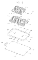
- FIG. 3 is a disassembled perspective view showing the wireless power transmitting device 100 in FIG. 2 .
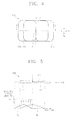
- FIG. 4 is a conceptual plane view showing a primary coil 110 of FIG. 2 .
- FIG. 5 is a conceptual view including a cross-section taken along a line V-V of FIG. 4 .
- FIG. 6 is a disassembled perspective view showing a wireless power transmitting device 100' in accordance with an exemplary embodiment that the wireless power transmitting device 100 of FIG. 3 is modified.
- FIG. 1 is a block diagram that shows a wireless power communication system in accordance with an exemplary embodiment.
- the wireless power communication system in accordance with an exemplary *embodiment includes a wireless power transmitting device 100 and a wireless power receiving device 200.
- the wireless power transmitting device 100 transmits a wireless power signal to the wireless power receiving device 200
- the wireless power receiving device 200 receiving the wireless power signal charges a battery with the power of the wireless power signal or supplies power to electronic devices connected to the wireless power receiving device 200.
- the wireless power transmitting device 100 includes a primary coil 110, a transmitting controller 120 and an alternating current/direct current (AC/DC) converter 130.
- the primary coil 110 is a device for transmitting a power signal to a secondary coil 210 of the wireless power receiving device 200 according to the electromagnetic induction method.
- three coils including a main coil 111, a first sub, coil 112 and a second sub coil 113 may be adopted as the primary coil 110.
- the three coils 111, 112, and 113 may be selectively operated by control of a transmitting controller 120.
- the transmitting controller 120 for controlling the primary coil 110 may include an object detector 121, a central controller 122, a switching controller 123, a driver 124 and a series resonant converter 125.
- the object detector 121 detects a load change of the primary coil 110, determines whether an object detected by the corresponding load change is the wireless power receiving apparatus 200, i.e., functions as an identification (ID) checker, and filters and processes a charging state signal transmitted from the wireless power receiving apparatus 200. For example, when an ID signal as a response signal to an ID call signal transmitted via the primary coil 110 is received, the object detecting unit 121 filters and processes the ID signal. When a charging state signal including information on a battery cell or a charging voltage is received, the object detecting unit 121 filters and processes the received information.
- ID identification
- the central controller 122 receives and checks a determination result of the object detector 121, analyzes an ID signal received via the primary coil 110, and transmits a power signal for transmitting a wireless power signal via the primary coil 110 to the driver 124. Also, when the charging state signal is received via the primary coil to be described below, the central controller 122 changes the wireless power signal by controlling the driver 124 based on the charging state signal.
- the switching controller 123 controls a switching operation of a switch among the coils 111 to 113 and the series resonant converter 125.
- the driver 124 controls the operation of the series resonant converter 125 by controlling the central controller 122.
- the series resonant converter 125 generates transmission power for generating a power signal to be transmitted by controlling the driver 124 and supplies the transmission power to one end of the primary coil 110.
- the driver 124 controls the operation of the series resonant converter 125 correspondingly to the transmitted power controlling signal.
- the series resonant converter 125 applies transmission power corresponding to the required power value to the primary coil 110 by controlling the driven 124 to transmit a wireless power signal with a required strength.
- the series resonant converter 125 supplies power for generating first to third object detecting signals via each of the main coil 111 and the first and second sub coils 112 and 113 by controlling of the driver 124.
- the AC/DC converter 130 is a device for converting an AC power of 220V or 110V into a DC power of a predetermined voltage. As described above, an output voltage value is changed by control of the central controller 122.
- the wireless power receiving apparatus 200 receiving power by receiving a power signal includes a secondary coil 210, a rectifier 220, a battery cell module 230 and a receiving controller 240.
- the secondary coil 210 generates induction power by the transmitted power signal.
- the rectifier 220 rectifies induced power.
- the battery cell module 230 is charged with the rectified power.
- the receiving controller 240 controls the secondary coil 210, the rectifier 220 and the battery cell module 230.
- the secondary coil 210 is configured to receive wireless power signal transmitted from the primary coil 110 of the wireless power transmitting device 100.
- the rectifier 220 rectifies a wireless power received from the secondary coil 210 into a DC voltage and maintains a charging state with a charging voltage before start of the charging.
- the battery cell module 230 is an object to be charged by the DC power from the rectifier 220 according to the control of the receiving controller 240.
- Electronic appliances such as PMP, MP3, and cellular phones may be charged instead of the battery cell module 230.
- the battery cell module 230 is configured to include protection circuits such as an over voltage and over currant preventing circuit and a temperature sensing circuit.
- a charging management module for collecting and processing the information including the charging state of the battery cell is included.
- the receiving controller 240 controls the current of the power charged in the rectifier 220 such that a proper current flows into the battery cell module 230.
- the wireless power transmitting device 100 and a core assembly as a part of the wireless power transmitting device 100 will be described in detail with reference to FIG. 2 to FIG. 6 .
- FIG. 2 is an assembled perspective view showing main elements of the wireless power transmitting device 100 in FIG.
- the wireless power transmitting device 100 may include a primary coil 110, a core 150, and a circuit board 170. Among them, the primary coil 110 and the core 150 are included in the core assembly.
- the primary coil 110 is formed of three coils including the main coil 111 and the auxiliary coils (the first sub coil 112 and the second sub coil 113).
- Each of the coils 111 to 113 is wound in one direction to have an oval shape, a track shape or a quadrangular shape.
- the main coil 111 may have the track shape.
- the main coil 111 of the track shape increases a freedom degree at a position of the wireless power receiving device 200.
- the coils 111 to 113 may be formed of a Litz type according to a method that a plurality of wires are twisted.
- Each of the coils 111 to 113 has two end portions (see FIG. 3 ).
- the auxiliary coils of the first sub coil 112 and the second sub coil 113 are disposed at a lower side, and the main coil 111 is disposed at an upper side of the first sub coil 112 and the second sub coil 113. Accordingly, if the main coil 111 is disposed at a first level, the first sub coil 112 and the second sub coil 113 may be disposed at a second level, which is different from and lower than the first level. Accordingly, the main coil 111 is disposed to be closer to a charging surface, in which the wireless power receiving device 200 is disposed, among outer surfaces of the wireless power transmitting device 100 than the auxiliary coil.
- each of the first sub coil 112 and the second sub coil 113 is partially overlapped with the main coil 111, and the overlapped portions of the coils 112 and 113 is not to be exposed to the outside. Also, since the auxiliary coils 112 and 113 are disposed to contact the lower surface of the main coil 111, a gap between the wireless power receiving device 200 and the auxiliary coils 112 and 113 is minimized.
- the core 150 having a material of a magnetic substance accommodates the primary coil 110.
- the core 150 may be formed of a plate shape.
- the core 150 generally has a rectangular shape. To be specific, a four corners of the rectangular shape have a round-treated shape.
- the circuit board 170 is disposed at a lower side of the core 150 to face a lower surface of the core 150. Singe an are of the circuit board 170 is wider than that of the core 150, a part 171 of the circuit board 170 (see FIG. 3 ) supports the core 150 from below. Another part 173 of the circuit board 170 (see FIG. 3 ) includes a circuit for controlling that power is applied to the primary coil 110.
- the control circuit may include the transmitting controller 120 and the AC/DC converter 130 (see FIG. 1 ) described above.
- at least one shield layer and insulating layer may be included in the circuit board 170 and the core 150. The shield layer and the insulating layer reduce a possibility that the magnetic field generated in the primary coil 110 affects the circuit board 170.
- FIG. 3 is cut disassembled perspective view showing the wireless power transmitting device 100 in FIG. 2 .
- the primary coil 110 include the main coil 111 and the auxiliary coils including the sub coils 112 and 113, whose area is respectively different from the main coil 111, as described above.
- the main coil 111 has a wider area than each of the first sub coil 112 and the second sub coil 113, and 15 disposed at an upper side than the sub coils 112 and 113.
- the main coil 111 includes two end portions 111a and 111b, and the first sub coil 112 includes two end portions 112a 112b.
- the second sub coil 113 also includes two end portions 113a and 113b.
- a concave portion 151 for accommodating the primary coil 110 is formed at a main surface of the core 150.
- the concave portion 151 is defined by a side wall 153 protruded to surround the concave portion 151.
- a plurality of extension grooves 156a, 156b, 157a, 157b, 158a and 158b for communicating the concave portion 151 with an outside is formed at the side wall 153.
- Each of both end portions of the coils 111 to 113 extends to an outside of the concave portion 151 via the extension grooves 156a, 156b, 157a, 157b, 158a and 158b to be connected to the circuit board 170.
- the core 150 is formed of a magnetic substance.
- the core 150 shields a magnetic field, which is out of a direction toward the wireless power receiving device 200 (see FIG. 1 ), among the magnetic fields by a current flowing in the coil 110 accommodated in the concave portion 151.
- the concave portion 151 is recessed to have a closed curve shape, i.e., a rectangular or oval shape outline.
- the concave portion 151 has a size for tightly accommodating an outer peripheral that the first sub coil 112 and the second sub coil 113 [and the main coil 111] disposed in parallel form together. Accordingly, since the first sub coil 112 and the second sub coil 113 are accommodated in the concave portion 151, the first sub coil 112 and the second sub coil 113 maintain a predetermined location inside the core 150.
- the wall 153 a height corresponding to go depth that the concave portion 151 is recessed.
- the side wall 153 has a size corresponding to a thickness of the primary coil 110 to shield or lessen that the magnetic field venerated in the coil 110 is leaked in a direction toward the side wall 153.
- an inner surface of the side wall 153 contacts an outer peripheral of the tightly accommodated primary coil 110 such that the coil 110 is disposed at a regular (predetermined) position.
- Supports 154 and 155 are formed to be protruded at a bottom of the concave portion 151. Each of the supports 154 and 155 is inserted into the hollow portion of the first sub coil 112 or is formed to be inserted into the hollow portion of the second sub coil 113. Accordingly, the supports 154 and 155 do not deviate from the position that the first sub coil 112 or the second sub coil 113 are set up, to thereby maintain the predetermined arrangement.
- Shapes of the supports 154 and 155 are formed to correspond to the shapes of inner peripherals of the hollow portions of the coils 112 and 113.
- the outer peripheral of the supports 154 and 155 has a curved section corresponding to the inner peripheral surface of the hollow portions having a curve shape.
- a position of the main coil 111 may be determined according to a method that the main coil 111 is attached to the first sub coil 112 and the second sub coil 113 by using a double-sided tape.
- the plurality of extension grooves 156a, 156b, 157a, 157b, 158a and 158b for connecting the concave portion 151 to the outside is formed at the side wall 153.
- the another pair of extension grooves 157a and 157b are formed at a position corresponding to both end portions 112a and 112b of the first sub coil 112.
- the other pair of extension grooves 158a and 158b are formed at a position corresponding to both end portions 113a and 113b of the second sub coil 113.
- An upper surface 171 of the circuit board 170 is disposed to face a lower surface of the core 150.
- Thorough holes 175 corresponding to the extension grooves 156a, 156b, 157a, 157b, 158a and 158b are formed along a long side of the circuit board 170. End portions of a primary core 110 passing through the thorough holes 175 are connected to a circuit pattern of the circuit board 170 at a lower surface of the circuit board 170.
- FIG. 4 is a conceptual plane view showing the primary coil 110 of FIG. 2 .
- FIG. 5 is a conceptual view including a cross-section taken along a line V-V of FIG. 4 .
- the main coil 111 has a width, which is longer than each width of the first sub coil 112 and the second sub coil 113 along the first direction W 1 .
- the main coil 111 has the width, which is smaller than a sum of each width of the first sub coil 112 and the second sub coil 113 along the first direction W 1 . Accordingly, a portion, which is out of the main coil 111 in each of the first sub coil 112 and the second sub coil 113, is exposed to the outside.
- the width of the main coil 111 in the direction W 1 may be 60 ⁇ 80% of the sum of the widths of the first sub coil 112 and the second sub coil 113.
- the width of the first sub coil 112 and the second sub coil 113 it means that the width of the main coil 111 is smaller than that of any one of the first sub coil 112 and the second sub coil 113. Further, if the width of the main Coil 111 is 100% of the sum of the widths of the first sub coil 112 and the second sub coil 113, it means that at least any one portion of the first sub coil 112 and the second sub coil 113 in the direction W 1 is not exposed to the outside. In the above two extreme cases, the present inventors recognized that the above ratio is proper when the main coil 111 mainly transmits a power signal to the wireless power receiving device 200 and the first sub coil 112 and the second sub coil 113 assist the main coil 111.
- the width of the main coil 111 in the same direction may be 70mm.
- a region corresponding to 35mm in width of the first sub coil 112 and the second sub coil 113 in the first direction W 1 may be covered with the main coil 111, and a region corresponding to 15mm in width of the first sub coil 112 and the second sub coil 113 in the first direction W 1 may be exposed to the outside.
- the coils 111 to 113 in a second direction W 2 may have the same width of 60mm.
- the width of the main coil 111 in the second direction W 2 may be the same as that of the first sub coil 112 and the second coil 113. Further, the first sub coil 112 and the second sub coil 113 may have the same size.
- the first direction W 1 is generally perpendicular to
- the first direction W 1 is generally perpendicular to the second direction W 2 and each of the coils 111 to 113 generally has a quadrangular shape.
- side surfaces facing the first sub coil 112 and the second sub coil 113 may meet at a line R, which passes a center C of the main coil 111.
- the main coil 111 since the main coil 111 is disposed at a center of the entire primary coil 110 to have the largest size the main coil 111 may be set up as a basic (default) coil for transmitting a wireless power signal.
- the wireless power receiving device 200 when the user locates the wireless power receiving device 200 at a neighborhood of a center of a surface for charging of the wireless power transmitting device 100, it is charged by the main coil 111.
- the wireless power receiving device 200 is out of the center of the charging surface, the first sub coil 112 or the second sub coil 113 operates to charge the wireless power receiving device 200.
- both of the first sub coil 112 and the second sub coil 113 are disposed at a level, which is just below the main coil 111, both of the first sub coil 112 and the second sub coil 113 do not become more distant from the wireless power receiving device 200. Accordingly, it is possible to reduce that the power signal transmitting efficiency of the wireless power receiving device 200 is deteriorated by the coil, which is remarkably spaced apart from the wireless power receiving device 200.
- the wireless power receiving device 200 of FIG. 1 may receive a wireless power signal by a regular magnetic flux.
- FIG. 5 shows a case that the second sub coil 113 cooperates with the maim coil 111.
- a magnetic field density M1 by the main coil 111 decreases from the center C of the main coil 111 to an end portion.
- a magnetic field density M2 by the second sub coil 113 also shows the similar aspect to the main coil 111.
- a magnetic field density M3 of a higher level is satisfied in a portion related to the second sub coil 113 in the main coil 111.
- the wireless power transmitting device 100 since a current divided into halves is applied to each of the main coil 111 and the second sub coil 113, a power loss as well as a thermal stress of the main coil 111 and the second sub coil 113 are reduced.
- FIG. 6 is a disassembled perspective view showing a wireless power transmitting device 100' in accordance with an exemplary embodiment that the wireless power transmitting device 100 of FIG. 3 is modified.
- the wireless power transmitting device 100' in accordance with the modified exemplary embodiment is generally similar to the wireless power transmitting device 100 in accordance with the former exemplary embodiment. However, there is a difference that the first sub coil 112 and the second sub coil 113 in accordance with the former exemplary embodiment are formed in a different shape.
- a 115 of an insulator is further included at a lower side of the main coil 111.
- Each of the first sub coil 112 and the second sub coil 113 in accordance with the former exemplary embodiment is formed of a first conductive pattern 112' and a second conductive pattern 113' formed on the base 115.
- a metal band extends in a spiral to form a plate shape.
- a conductive pattern indicates the whole of the first conductive pattern 112' and the second conductive pattern 113'.
- the first conductive pattern 112' and the second conductive pattern 113' may be formed at a time via an etching process after attaching a metal plate such as a copper plate to the base 115. Since the first conductive pattern 112' and the second conductive pattern 113' form an auxiliary coil as one member by using the base 115 as a medium, a process for assembling the primary coil 110 may be simplified. Also, the core 150 does not need the supports 154 and 155 of FIG, 3 .
- first conductive pattern 112' and the second conductive pattern 113' may be formed to be thinner than the first sub coil 112 and the second sub coil 113, a distance from a center of the first conducive pattern 112 and the second conductive pattern 113' in a thickness direction to the wireless power receiving device 200 is closer than that of the first sub coil 112 and the second sub coil 113 in accordance with the former exemplary embodiment. Accordingly, there is an advantage that a transmitting efficiency of the wireless power signal to the wireless power receiving device 200 is improved.
- the core assembly for the wireless power transmitting device in accordance with the exemplary embodiment and the wireless power transmitting device having the same it is possible to increase a freedom degree of a right position, in which the wireless power receiving device for receiving power from the wireless power transmitting device is to be disposed, by widening a rechargeable area via two sub coils disposed at different levels.
- the core assembly for the wireless power transmitting device and the wireless power transmitting device having the same may not be limitedly applied by the configuration and method of the above-mentioned exemplary embodiment. All or the part of the exemplary embodiments may be selectively combined and configured to realize diverse modifications.
Landscapes
- Engineering & Computer Science (AREA)
- Computer Networks & Wireless Communication (AREA)
- Power Engineering (AREA)
- Signal Processing (AREA)
- Physics & Mathematics (AREA)
- Electromagnetism (AREA)
- Charge And Discharge Circuits For Batteries Or The Like (AREA)
- Near-Field Transmission Systems (AREA)
- Coils Or Transformers For Communication (AREA)
Applications Claiming Priority (1)
| Application Number | Priority Date | Filing Date | Title |
|---|---|---|---|
| KR1020110070145A KR101213090B1 (ko) | 2011-07-14 | 2011-07-14 | 무선전력 전송장치용 코어 어셈블리 및 그를 구비하는 무선전력 전송장치 |
Publications (3)
| Publication Number | Publication Date |
|---|---|
| EP2546998A2 true EP2546998A2 (de) | 2013-01-16 |
| EP2546998A3 EP2546998A3 (de) | 2017-04-19 |
| EP2546998B1 EP2546998B1 (de) | 2019-09-18 |
Family
ID=46762837
Family Applications (1)
| Application Number | Title | Priority Date | Filing Date |
|---|---|---|---|
| EP12176332.0A Active EP2546998B1 (de) | 2011-07-14 | 2012-07-13 | Kernbaugruppe für eine drahtlose Leistungssendevorrichtung, und drahtlose Leistungssendevorrichtung mit dieser Kernbaugruppe |
Country Status (5)
| Country | Link |
|---|---|
| US (1) | US9906274B2 (de) |
| EP (1) | EP2546998B1 (de) |
| JP (1) | JP5686769B2 (de) |
| KR (1) | KR101213090B1 (de) |
| CN (1) | CN102882283B (de) |
Cited By (3)
| Publication number | Priority date | Publication date | Assignee | Title |
|---|---|---|---|---|
| EP3166204A4 (de) * | 2014-07-02 | 2017-07-26 | Panasonic Intellectual Property Management Co., Ltd. | Ladevorrichtung für tragbares endgerät |
| WO2017204597A1 (en) * | 2016-05-27 | 2017-11-30 | Samsung Electronics Co., Ltd. | Wireless power receiver |
| US10340078B2 (en) | 2013-12-17 | 2019-07-02 | Witricity Corporation | Coil topologies for inductive power transfer |
Families Citing this family (91)
| Publication number | Priority date | Publication date | Assignee | Title |
|---|---|---|---|---|
| KR101134625B1 (ko) * | 2010-07-16 | 2012-04-09 | 주식회사 한림포스텍 | 무선 전력 통신용 코어 어셈블리와 그를 구비하는 무선 전력 통신용 전력 공급 장치, 그리고 무선 전력 통신용 코어 어셈블리 제조 방법 |
| CN103814502A (zh) * | 2011-09-21 | 2014-05-21 | 丰田自动车株式会社 | 非接触送电装置、非接触受电装置以及非接触送受电系统 |
| TW201429105A (zh) * | 2013-01-04 | 2014-07-16 | 致伸科技股份有限公司 | 無線充電傳輸裝置 |
| DE102013101057B4 (de) * | 2013-02-01 | 2017-01-26 | Thyssenkrupp Rothe Erde Gmbh | Flächiger Induktor |
| KR101622694B1 (ko) * | 2013-06-17 | 2016-05-19 | 엘지전자 주식회사 | 무선 전력 전송방법, 무선 전력 전송장치 및 무선 충전 시스템 |
| KR101613956B1 (ko) * | 2013-06-03 | 2016-04-20 | 엘지전자 주식회사 | 무선 전력 전송방법, 무선 전력 전송장치 및 무선 충전 시스템 |
| EP2811614B1 (de) | 2013-06-03 | 2017-10-25 | LG Electronics, Inc. | Drahtloses Stromübertragungsverfahren, drahtloser Stromsender und drahtloses Ladesystem |
| KR101477408B1 (ko) * | 2013-07-23 | 2014-12-29 | 삼성전기주식회사 | 코어를 포함하는 코일 시트 및 이를 포함하는 무접점 전력 전송 장치 |
| KR101456795B1 (ko) | 2013-08-26 | 2014-10-31 | 숭실대학교산학협력단 | 칩 간 무선 전력 전송을 위한 안테나 |
| US9762068B2 (en) | 2013-09-26 | 2017-09-12 | Fairchild Korea Semiconductor Ltd. | Wireless power transfer system |
| KR102236576B1 (ko) * | 2013-09-26 | 2021-04-05 | 온세미컨덕터코리아 주식회사 | 무선 전력 전달 시스템 |
| DE102013219540A1 (de) * | 2013-09-27 | 2015-04-02 | Siemens Aktiengesellschaft | Ladeanordnung zur induktiven drahtlosen Abgabe von Energie |
| KR101649655B1 (ko) * | 2013-11-18 | 2016-08-19 | 엘지전자 주식회사 | 무선 전력 전송 장치 및 그 제어 방법 |
| US9490656B2 (en) | 2013-11-25 | 2016-11-08 | A.K. Stamping Company, Inc. | Method of making a wireless charging coil |
| US9859052B2 (en) * | 2013-11-25 | 2018-01-02 | A.K. Stamping Co., Inc. | Wireless charging coil |
| KR101522572B1 (ko) * | 2014-01-03 | 2015-05-26 | 영보엔지니어링 주식회사 | 휴대기기용 무선충전 배터리장치 |
| US10461582B2 (en) * | 2014-03-31 | 2019-10-29 | Qualcomm Incorporated | Systems, apparatus, and methods for wireless power receiver coil configuration |
| KR102166881B1 (ko) | 2014-04-03 | 2020-10-16 | 엘지이노텍 주식회사 | 무선 전력 송신 장치 |
| JP6500509B2 (ja) * | 2014-04-25 | 2019-04-17 | Tdk株式会社 | コイルユニット |
| CN105098998B (zh) | 2014-05-16 | 2020-02-11 | 泰科电子(上海)有限公司 | 无线电力传输装置 |
| KR20160037652A (ko) * | 2014-09-29 | 2016-04-06 | 엘지이노텍 주식회사 | 무선 전력 송신 장치 및 무선 전력 수신 장치 |
| KR20160038315A (ko) * | 2014-09-30 | 2016-04-07 | 엘지이노텍 주식회사 | 무선 전력 송신 장치 |
| KR101765692B1 (ko) * | 2014-11-07 | 2017-08-07 | 주식회사 아모센스 | 무선충전기용 송신장치 |
| CN105742009B (zh) * | 2014-12-26 | 2019-01-04 | 株式会社村田制作所 | 表面贴装电感器及其制造方法 |
| US9912172B2 (en) * | 2015-01-14 | 2018-03-06 | Qualcomm Incorporated | Asymmetrically layered stacked coils and/or chamfered ferrite in wireless power transfer applications |
| KR102105395B1 (ko) * | 2015-01-19 | 2020-04-28 | 삼성전기주식회사 | 칩 전자부품 및 칩 전자부품의 실장 기판 |
| KR101659397B1 (ko) * | 2015-03-10 | 2016-09-23 | 주식회사 핀크래프트엔지니어링 | 슬림형 무선 충전 송수신기 |
| US10347414B2 (en) * | 2015-05-14 | 2019-07-09 | Maxlinear, Inc. | Method and system for winding transformers to maximize symmetry of the primary and secondary coils |
| CN106160268B (zh) * | 2015-05-15 | 2020-11-06 | 松下知识产权经营株式会社 | 异物检测装置、无线送电装置以及无线电力传送系统 |
| EP3093957B1 (de) | 2015-05-15 | 2022-05-18 | Panasonic Intellectual Property Management Co., Ltd. | Fremdkörperdetektionsvorrichtung, vorrichtung zur drahtlosen stromübertragung und system zur drahtlosen stromübertragung |
| WO2016190708A1 (ko) | 2015-05-28 | 2016-12-01 | 주식회사 아모센스 | 무선전력 전송용 안테나유닛 및 이를 포함하는 무선전력 송신모듈 |
| JP6650219B2 (ja) | 2015-06-25 | 2020-02-19 | ローム株式会社 | 送電装置及び非接触給電システム |
| KR101690500B1 (ko) * | 2015-07-20 | 2016-12-28 | 주식회사 아모센스 | 무선전력 송신모듈 |
| US10985465B2 (en) * | 2015-08-19 | 2021-04-20 | Nucurrent, Inc. | Multi-mode wireless antenna configurations |
| EP3331129B1 (de) * | 2015-08-26 | 2020-04-08 | Rohm Co., Ltd. | Stromübertragungsvorrichtung und kontaktloses stromversorgungsverfahren |
| KR101727463B1 (ko) * | 2015-10-15 | 2017-04-17 | 주식회사 서연전자 | 자기유도 코일조립체 |
| KR20170050991A (ko) * | 2015-11-02 | 2017-05-11 | 엘지이노텍 주식회사 | 무선 전력 송신기 |
| CN107438934B (zh) | 2015-11-05 | 2020-10-02 | Lg 电子株式会社 | 用于车辆的无线电力发射机和接收机 |
| CN106887906B (zh) * | 2015-12-16 | 2024-06-18 | 泰科电子(上海)有限公司 | 无线供电装置和电气设备 |
| KR101804410B1 (ko) * | 2015-12-17 | 2017-12-04 | 엘지이노텍 주식회사 | 무선 전력 송신기를 위한 송신 코일 모듈 |
| KR20170076170A (ko) * | 2015-12-24 | 2017-07-04 | 엘지이노텍 주식회사 | 다중 모드를 지원하는 무선 전력 송신기 |
| KR102610789B1 (ko) * | 2016-06-28 | 2023-12-06 | 엘지이노텍 주식회사 | 복수의 코일을 포함하는 무선 전력 송신기 제어 방법 및 장치 |
| KR20180017687A (ko) * | 2016-08-10 | 2018-02-21 | 삼성전기주식회사 | 코일 조립체 |
| KR101969508B1 (ko) * | 2016-10-06 | 2019-04-16 | 백정엽 | 싱글 와이어 광대역 충전 코일을 포함한 무선충전장치 |
| KR101810869B1 (ko) * | 2016-12-29 | 2017-12-26 | 김민준 | 무선 전력 전송용 코일 및 무선 전력 송수신 시스템 |
| KR101909349B1 (ko) * | 2016-12-29 | 2018-10-17 | 주식회사 켐트로닉스 | 무선충전기용 tx 코일 구조체 |
| CN110603641B (zh) * | 2017-03-06 | 2023-09-12 | Lg伊诺特有限公司 | 线圈装置 |
| KR102338933B1 (ko) * | 2017-03-06 | 2021-12-14 | 엘지이노텍 주식회사 | 코일 장치 및 코일 장치를 포함하는 무선 전력 송수신 장치 |
| US20180269710A1 (en) * | 2017-03-16 | 2018-09-20 | Shenzhen Yichong Wireless Power Technology Co. Ltd. | Power transmitter coil in wireless charging system |
| CN106953417A (zh) * | 2017-03-30 | 2017-07-14 | 上海交通大学 | 无线充电线圈组件及使用该组件的电能传输系统 |
| KR101833738B1 (ko) * | 2017-07-07 | 2018-03-02 | 엘지이노텍 주식회사 | 무선전력전송 시스템 |
| EP3438996B1 (de) * | 2017-08-02 | 2021-09-22 | Ningbo Geely Automobile Research & Development Co., Ltd. | Vorrichtung für ein system zur drahtlosen stromübertragung für ein fahrzeug |
| KR101853068B1 (ko) * | 2017-08-16 | 2018-06-04 | 엘지이노텍 주식회사 | 무선 전력 충전기를 위한 자성 차폐 블록 제조 방법 |
| JP6669710B2 (ja) * | 2017-11-16 | 2020-03-18 | 矢崎総業株式会社 | 電力伝送通信ユニット |
| KR20190087761A (ko) * | 2018-01-17 | 2019-07-25 | 현대자동차주식회사 | 전기차 무선 전력 전송 시스템에서 다양한 구조의 페라이트를 내장한 무선 충전 패드 |
| KR102116570B1 (ko) * | 2018-01-19 | 2020-05-28 | 엘지전자 주식회사 | 공기 청정기 |
| DE202019100290U1 (de) | 2018-01-19 | 2019-06-24 | Lg Electronics Inc. | Luftreiniger |
| KR102116572B1 (ko) | 2018-01-19 | 2020-05-28 | 엘지전자 주식회사 | 가습 공기청정기 |
| DE202019100292U1 (de) | 2018-01-19 | 2019-05-09 | Lg Electronics Inc. | Luftreiniger |
| KR101905885B1 (ko) | 2018-02-20 | 2018-10-08 | 엘지이노텍 주식회사 | 무선전력 송신기 |
| US11404910B2 (en) | 2018-03-23 | 2022-08-02 | Raytheon Company | Multi-cell inductive wireless power transfer system |
| KR102531048B1 (ko) | 2018-04-26 | 2023-05-10 | 주식회사 아모센스 | 회전형 연결부용 무선전력 전송 시스템 |
| KR102565136B1 (ko) * | 2018-06-05 | 2023-08-08 | 주식회사 히타치엘지 데이터 스토리지 코리아 | 무선 전력 송수신용 코일 |
| KR102615237B1 (ko) * | 2018-06-27 | 2023-12-19 | 삼성전자주식회사 | 적층 코일 구조 및 이를 포함하는 전자 장치 |
| US11159054B2 (en) | 2018-07-24 | 2021-10-26 | Apple Inc. | Wireless power transmitting devices |
| WO2020041478A1 (en) * | 2018-08-21 | 2020-02-27 | Molex Cvs Grand Blanc, Llc | Coil topologies for wireless charging power transmitters |
| CN209496712U (zh) * | 2018-12-27 | 2019-10-15 | 泰科电子(上海)有限公司 | 无线供电装置以及具有该无线供电装置的电气设备 |
| KR102624909B1 (ko) * | 2018-12-28 | 2024-01-12 | 엘지전자 주식회사 | 다중 코일을 이용한 무선 충전 장치 및 이를 포함하는 무선 충전 시스템 |
| JP7283127B2 (ja) * | 2019-02-27 | 2023-05-30 | Tdk株式会社 | コイル部品 |
| WO2020236922A1 (en) * | 2019-05-21 | 2020-11-26 | General Electric Company | Wireless power transmission apparatus with multiple primary coils and adjacent coil muting |
| EP4032168A4 (de) * | 2019-09-16 | 2023-11-01 | Utah State University | Grundplatte für dynamische drahtlosleistungsübertragung |
| KR102313298B1 (ko) * | 2019-09-23 | 2021-10-14 | 엘지전자 주식회사 | 무선 전력 전송 장치 및 이를 포함하는 시스템 |
| KR102366905B1 (ko) * | 2020-03-30 | 2022-02-24 | 니덱모빌리티코리아 주식회사 | 일체형 베이스를 갖는 차량용 무선 충전 장치 |
| US11476722B2 (en) | 2020-04-30 | 2022-10-18 | Nucurrent, Inc. | Precision power level control for extended range wireless power transfer |
| US11239709B2 (en) | 2020-04-30 | 2022-02-01 | Nucurrent, Inc. | Operating frequency based power level altering in extended range wireless power transmitters |
| US11482890B2 (en) | 2020-04-30 | 2022-10-25 | Nucurrent, Inc. | Surface mountable wireless power transmitter for transmission at extended range |
| US11387674B1 (en) | 2020-12-23 | 2022-07-12 | Nucurrent, Inc. | Wireless power transmitters for transmitting power at extended separation distances utilizing concave shielding |
| US11387684B1 (en) | 2020-12-23 | 2022-07-12 | Nucurrent, Inc. | Wireless power transmitters and associated base stations for transmitting power at extended separation distances |
| US11757311B2 (en) | 2020-12-23 | 2023-09-12 | Nucurrent, Inc. | Wireless power transmitters and associated base stations for transmitting power at extended separation distances |
| US11637459B2 (en) | 2020-12-23 | 2023-04-25 | Nucurrent, Inc. | Wireless power transmitters for transmitting power at extended separation distances utilizing T-Core shielding |
| US11476711B2 (en) | 2020-12-23 | 2022-10-18 | Nucurrent, Inc. | Wireless power transmitters and associated base stations for through-structure charging |
| WO2022140612A1 (en) * | 2020-12-23 | 2022-06-30 | Nucurrent, Inc. | Wireless power transmitters and associated base stations for transmitting power at extended separation distances |
| US11942799B2 (en) | 2021-04-30 | 2024-03-26 | Nucurrent, Inc. | False notification suppression in wireless power transfer system |
| US11791667B2 (en) | 2021-04-30 | 2023-10-17 | Nucurrent, Inc. | Power capability detection for wireless power transmission based on receiver power request |
| US11482891B1 (en) | 2021-04-20 | 2022-10-25 | Nucurrent, Inc. | Timing verification in precision power level control systems for wireless power transmission |
| US11532956B2 (en) | 2021-04-30 | 2022-12-20 | Nucurrent, Inc. | Power capability detection with verification load in power level control systems for wireless power transmission |
| US11539247B2 (en) | 2021-04-30 | 2022-12-27 | Nucurrent, Inc. | Power capability detection in precision power level control systems for wireless power transmission |
| US11967830B2 (en) * | 2021-10-12 | 2024-04-23 | Nucurrent, Inc. | Wireless power transmitters for transmitting power at extended separation distances with magnetic connectors |
| US12132325B2 (en) | 2021-10-12 | 2024-10-29 | Nucurrent, Inc. | Wireless power transmitter with removable magnetic connector panel |
| US11637448B1 (en) | 2021-10-12 | 2023-04-25 | Nucurrent, Inc. | Wireless power transmitter with removable magnetic connector panel for vehicular use |
| KR20240007419A (ko) * | 2022-07-08 | 2024-01-16 | 주식회사 아모센스 | 사출형 자기장 차폐부재 및 이를 포함하는 무선전력 수신모듈 |
Family Cites Families (31)
| Publication number | Priority date | Publication date | Assignee | Title |
|---|---|---|---|---|
| JPH08148359A (ja) * | 1994-11-18 | 1996-06-07 | Tdk Corp | Lan用コネクタ |
| JPH11265814A (ja) * | 1998-03-17 | 1999-09-28 | Matsushita Electric Ind Co Ltd | コイル部品およびそれを用いた電子機器 |
| JP2002320337A (ja) * | 2001-04-20 | 2002-10-31 | Matsushita Electric Ind Co Ltd | 電子機器 |
| AU2003282214A1 (en) * | 2002-10-28 | 2004-05-13 | Splashpower Limited | Unit and system for contactless power transfer |
| JP2004229406A (ja) * | 2003-01-23 | 2004-08-12 | Sony Corp | 分離トランス装置 |
| US7233137B2 (en) * | 2003-09-30 | 2007-06-19 | Sharp Kabushiki Kaisha | Power supply system |
| KR100819604B1 (ko) * | 2005-07-27 | 2008-04-03 | 엘에스전선 주식회사 | 충전효율의 편차가 개선된 무선 충전기 |
| US8169185B2 (en) * | 2006-01-31 | 2012-05-01 | Mojo Mobility, Inc. | System and method for inductive charging of portable devices |
| JP4209437B2 (ja) * | 2006-11-10 | 2009-01-14 | 三菱重工業株式会社 | 移動体の非接触給電装置及びその保護装置 |
| JP2008135589A (ja) * | 2006-11-29 | 2008-06-12 | Asuka Electron Kk | 電力伝送用コイル |
| JP5224442B2 (ja) * | 2007-12-28 | 2013-07-03 | Necトーキン株式会社 | 非接触電力伝送装置 |
| CN101971452B (zh) * | 2008-03-13 | 2014-06-04 | 捷通国际有限公司 | 具有多个线圈初级的感应电源系统 |
| JP5682992B2 (ja) | 2008-04-04 | 2015-03-11 | Necトーキン株式会社 | 非接触電力伝送装置 |
| US9601261B2 (en) * | 2008-09-27 | 2017-03-21 | Witricity Corporation | Wireless energy transfer using repeater resonators |
| US8912687B2 (en) * | 2008-09-27 | 2014-12-16 | Witricity Corporation | Secure wireless energy transfer for vehicle applications |
| CN103227513B (zh) * | 2008-12-12 | 2016-07-06 | 英特尔公司 | 非接触输电设备 |
| US9130395B2 (en) * | 2008-12-12 | 2015-09-08 | Hanrim Postech Co., Ltd. | Non-contact charging station with planar spiral power transmission coil and method for controlling the same |
| KR100971705B1 (ko) | 2009-09-03 | 2010-07-22 | 주식회사 한림포스텍 | 무접점 충전 시스템 |
| ES2687775T3 (es) * | 2008-12-12 | 2018-10-29 | Ge Hybrid Technologies, Llc | Estación de carga sin contacto equipada con un núcleo de PTPS que tiene una estructura de núcleo en espiral plana, un aparato de recepción de energía sin contacto y un procedimiento para controlar la misma |
| KR101745735B1 (ko) * | 2009-04-08 | 2017-06-12 | 액세스 비지니스 그룹 인터내셔날 엘엘씨 | 선택 가능한 코일 어레이 |
| TWI451458B (zh) * | 2009-08-25 | 2014-09-01 | Access Business Group Int Llc | 磁通量集中器及製造一磁通量集中器的方法 |
| KR101134625B1 (ko) | 2010-07-16 | 2012-04-09 | 주식회사 한림포스텍 | 무선 전력 통신용 코어 어셈블리와 그를 구비하는 무선 전력 통신용 전력 공급 장치, 그리고 무선 전력 통신용 코어 어셈블리 제조 방법 |
| WO2012018268A1 (en) * | 2010-08-05 | 2012-02-09 | Auckland Uniservices Limited | Inductive power transfer apparatus |
| KR101228556B1 (ko) * | 2010-11-04 | 2013-02-07 | 주식회사 한림포스텍 | 무선 전력 전송 장치에서의 전력 전송 코일 선택 제어 방법, 이를 적용한 무선 전력 전송 장치, 및 이를 적용하는 무선 전력 전송 시스템 |
| KR101213086B1 (ko) * | 2010-11-04 | 2012-12-18 | 유한회사 한림포스텍 | 무선 전력 전송 장치에서의 무선 전력 신호 제어 방법 및 이를 이용하는 무선 전력 전송 장치 |
| CN201887566U (zh) * | 2010-11-19 | 2011-06-29 | 昆盈企业股份有限公司 | 电脑输入装置的非接触式供电装置 |
| KR101267076B1 (ko) * | 2011-03-24 | 2013-05-24 | 주식회사 한림포스텍 | 무선 전력 전송 어셈블리에서의 전력 제어 방법 및 무선 전력 전송 어셈블리 |
| CN103636098A (zh) * | 2011-06-10 | 2014-03-12 | 捷通国际有限公司 | 用于检测、表征以及跟踪感应电力接收器的系统和方法 |
| KR101246692B1 (ko) * | 2011-07-14 | 2013-03-21 | 주식회사 한림포스텍 | 무선전력 통신시스템용 전력 전송장치 |
| KR101305303B1 (ko) * | 2011-09-21 | 2013-09-06 | 주식회사 한림포스텍 | 무선 전력전송장치 및 방법 |
| US9666357B2 (en) * | 2012-09-11 | 2017-05-30 | Qualcomm Incorporated | Apparatus system, and method for wirelessly receiving power using conductive structures |
-
2011
- 2011-07-14 KR KR1020110070145A patent/KR101213090B1/ko not_active Expired - Fee Related
-
2012
- 2012-07-13 EP EP12176332.0A patent/EP2546998B1/de active Active
- 2012-07-13 JP JP2012157846A patent/JP5686769B2/ja active Active
- 2012-07-16 CN CN201210244903.5A patent/CN102882283B/zh active Active
- 2012-07-16 US US13/550,201 patent/US9906274B2/en active Active
Cited By (5)
| Publication number | Priority date | Publication date | Assignee | Title |
|---|---|---|---|---|
| US10340078B2 (en) | 2013-12-17 | 2019-07-02 | Witricity Corporation | Coil topologies for inductive power transfer |
| EP3166204A4 (de) * | 2014-07-02 | 2017-07-26 | Panasonic Intellectual Property Management Co., Ltd. | Ladevorrichtung für tragbares endgerät |
| WO2017204597A1 (en) * | 2016-05-27 | 2017-11-30 | Samsung Electronics Co., Ltd. | Wireless power receiver |
| EP3449549A4 (de) * | 2016-05-27 | 2019-05-08 | Samsung Electronics Co., Ltd. | Drahtloser leistungsempfänger |
| US10511192B2 (en) | 2016-05-27 | 2019-12-17 | Samsung Electronics Co., Ltd | Wireless power receiver |
Also Published As
| Publication number | Publication date |
|---|---|
| CN102882283A (zh) | 2013-01-16 |
| EP2546998B1 (de) | 2019-09-18 |
| JP2013026623A (ja) | 2013-02-04 |
| JP5686769B2 (ja) | 2015-03-18 |
| EP2546998A3 (de) | 2017-04-19 |
| US20130015719A1 (en) | 2013-01-17 |
| US9906274B2 (en) | 2018-02-27 |
| CN102882283B (zh) | 2017-04-12 |
| KR101213090B1 (ko) | 2012-12-18 |
Similar Documents
| Publication | Publication Date | Title |
|---|---|---|
| EP2546998B1 (de) | Kernbaugruppe für eine drahtlose Leistungssendevorrichtung, und drahtlose Leistungssendevorrichtung mit dieser Kernbaugruppe | |
| US9264107B2 (en) | Wireless power transmitting device for wireless power communication system | |
| US10992184B2 (en) | Non-contact power reception apparatus for non-contact charging and electronic settlement performed in a single portable terminal | |
| KR101228556B1 (ko) | 무선 전력 전송 장치에서의 전력 전송 코일 선택 제어 방법, 이를 적용한 무선 전력 전송 장치, 및 이를 적용하는 무선 전력 전송 시스템 | |
| US9608697B2 (en) | Wireless power transmitting apparatus and method thereof | |
| KR101134625B1 (ko) | 무선 전력 통신용 코어 어셈블리와 그를 구비하는 무선 전력 통신용 전력 공급 장치, 그리고 무선 전력 통신용 코어 어셈블리 제조 방법 | |
| KR101810003B1 (ko) | 배터리가 내장된 휴대단말기용 케이스 | |
| EP2683054B1 (de) | Drahtloses System mit mehreren Ladegeräten und Steuerverfahren dafür | |
| EP2595162B1 (de) | Drahtlose Leistungsübertragungsvorrichtung | |
| KR101461549B1 (ko) | 비접촉 충전 모듈 및 비접촉 충전 기기 | |
| JP6122402B2 (ja) | 送電装置および無線電力伝送システム | |
| CN102457109A (zh) | 控制无线输电设备中无线电力信号的方法及无线输电设备 | |
| JP2008295274A (ja) | 無接点電力伝送コイルユニット、携帯端末、送電装置、及び、無接点電力伝送システム | |
| WO2012039245A1 (ja) | 非接触式電力伝送用のコイルモジュール、およびこれを具備する電池パックおよび充電装置 | |
| KR101239305B1 (ko) | 무선전력통신용 코어 어셈블리와 그를 구비하는 무선전력통신용 전력공급장치, 그리고 무선전력통신용 코어 어셈블리 제조 방법 | |
| KR20100067749A (ko) | 평면나선형 코어구조의 파워트랜스피씨비코어가 복층형으로구비된 멀티무접점충전스테이션 | |
| US20190370427A1 (en) | Coil for transmitting or receiving power wirelessly | |
| US10084351B2 (en) | Power feeding device | |
| JP2014093797A (ja) | 電力伝送システム | |
| JP2018143058A (ja) | 送電装置 |
Legal Events
| Date | Code | Title | Description |
|---|---|---|---|
| PUAI | Public reference made under article 153(3) epc to a published international application that has entered the european phase |
Free format text: ORIGINAL CODE: 0009012 |
|
| AK | Designated contracting states |
Kind code of ref document: A2 Designated state(s): AL AT BE BG CH CY CZ DE DK EE ES FI FR GB GR HR HU IE IS IT LI LT LU LV MC MK MT NL NO PL PT RO RS SE SI SK SM TR |
|
| AX | Request for extension of the european patent |
Extension state: BA ME |
|
| PUAL | Search report despatched |
Free format text: ORIGINAL CODE: 0009013 |
|
| AK | Designated contracting states |
Kind code of ref document: A3 Designated state(s): AL AT BE BG CH CY CZ DE DK EE ES FI FR GB GR HR HU IE IS IT LI LT LU LV MC MK MT NL NO PL PT RO RS SE SI SK SM TR |
|
| AX | Request for extension of the european patent |
Extension state: BA ME |
|
| RIC1 | Information provided on ipc code assigned before grant |
Ipc: H04B 5/00 20060101AFI20170313BHEP Ipc: H02J 5/00 20160101ALI20170313BHEP |
|
| STAA | Information on the status of an ep patent application or granted ep patent |
Free format text: STATUS: REQUEST FOR EXAMINATION WAS MADE |
|
| 17P | Request for examination filed |
Effective date: 20171017 |
|
| RBV | Designated contracting states (corrected) |
Designated state(s): AL AT BE BG CH CY CZ DE DK EE ES FI FR GB GR HR HU IE IS IT LI LT LU LV MC MK MT NL NO PL PT RO RS SE SI SK SM TR |
|
| STAA | Information on the status of an ep patent application or granted ep patent |
Free format text: STATUS: EXAMINATION IS IN PROGRESS |
|
| 17Q | First examination report despatched |
Effective date: 20171122 |
|
| RAP1 | Party data changed (applicant data changed or rights of an application transferred) |
Owner name: GE HYBRID TECHNOLOGIES, LLC |
|
| GRAP | Despatch of communication of intention to grant a patent |
Free format text: ORIGINAL CODE: EPIDOSNIGR1 |
|
| STAA | Information on the status of an ep patent application or granted ep patent |
Free format text: STATUS: GRANT OF PATENT IS INTENDED |
|
| INTG | Intention to grant announced |
Effective date: 20190412 |
|
| GRAS | Grant fee paid |
Free format text: ORIGINAL CODE: EPIDOSNIGR3 |
|
| GRAA | (expected) grant |
Free format text: ORIGINAL CODE: 0009210 |
|
| STAA | Information on the status of an ep patent application or granted ep patent |
Free format text: STATUS: THE PATENT HAS BEEN GRANTED |
|
| AK | Designated contracting states |
Kind code of ref document: B1 Designated state(s): AL AT BE BG CH CY CZ DE DK EE ES FI FR GB GR HR HU IE IS IT LI LT LU LV MC MK MT NL NO PL PT RO RS SE SI SK SM TR |
|
| REG | Reference to a national code |
Ref country code: GB Ref legal event code: FG4D |
|
| REG | Reference to a national code |
Ref country code: CH Ref legal event code: EP |
|
| REG | Reference to a national code |
Ref country code: DE Ref legal event code: R096 Ref document number: 602012064051 Country of ref document: DE |
|
| REG | Reference to a national code |
Ref country code: AT Ref legal event code: REF Ref document number: 1182532 Country of ref document: AT Kind code of ref document: T Effective date: 20191015 |
|
| REG | Reference to a national code |
Ref country code: IE Ref legal event code: FG4D |
|
| REG | Reference to a national code |
Ref country code: NL Ref legal event code: MP Effective date: 20190918 |
|
| PG25 | Lapsed in a contracting state [announced via postgrant information from national office to epo] |
Ref country code: NO Free format text: LAPSE BECAUSE OF FAILURE TO SUBMIT A TRANSLATION OF THE DESCRIPTION OR TO PAY THE FEE WITHIN THE PRESCRIBED TIME-LIMIT Effective date: 20191218 Ref country code: BG Free format text: LAPSE BECAUSE OF FAILURE TO SUBMIT A TRANSLATION OF THE DESCRIPTION OR TO PAY THE FEE WITHIN THE PRESCRIBED TIME-LIMIT Effective date: 20191218 Ref country code: SE Free format text: LAPSE BECAUSE OF FAILURE TO SUBMIT A TRANSLATION OF THE DESCRIPTION OR TO PAY THE FEE WITHIN THE PRESCRIBED TIME-LIMIT Effective date: 20190918 Ref country code: HR Free format text: LAPSE BECAUSE OF FAILURE TO SUBMIT A TRANSLATION OF THE DESCRIPTION OR TO PAY THE FEE WITHIN THE PRESCRIBED TIME-LIMIT Effective date: 20190918 Ref country code: FI Free format text: LAPSE BECAUSE OF FAILURE TO SUBMIT A TRANSLATION OF THE DESCRIPTION OR TO PAY THE FEE WITHIN THE PRESCRIBED TIME-LIMIT Effective date: 20190918 Ref country code: LT Free format text: LAPSE BECAUSE OF FAILURE TO SUBMIT A TRANSLATION OF THE DESCRIPTION OR TO PAY THE FEE WITHIN THE PRESCRIBED TIME-LIMIT Effective date: 20190918 |
|
| REG | Reference to a national code |
Ref country code: LT Ref legal event code: MG4D |
|
| PG25 | Lapsed in a contracting state [announced via postgrant information from national office to epo] |
Ref country code: GR Free format text: LAPSE BECAUSE OF FAILURE TO SUBMIT A TRANSLATION OF THE DESCRIPTION OR TO PAY THE FEE WITHIN THE PRESCRIBED TIME-LIMIT Effective date: 20191219 Ref country code: AL Free format text: LAPSE BECAUSE OF FAILURE TO SUBMIT A TRANSLATION OF THE DESCRIPTION OR TO PAY THE FEE WITHIN THE PRESCRIBED TIME-LIMIT Effective date: 20190918 Ref country code: LV Free format text: LAPSE BECAUSE OF FAILURE TO SUBMIT A TRANSLATION OF THE DESCRIPTION OR TO PAY THE FEE WITHIN THE PRESCRIBED TIME-LIMIT Effective date: 20190918 Ref country code: RS Free format text: LAPSE BECAUSE OF FAILURE TO SUBMIT A TRANSLATION OF THE DESCRIPTION OR TO PAY THE FEE WITHIN THE PRESCRIBED TIME-LIMIT Effective date: 20190918 |
|
| REG | Reference to a national code |
Ref country code: AT Ref legal event code: MK05 Ref document number: 1182532 Country of ref document: AT Kind code of ref document: T Effective date: 20190918 |
|
| PG25 | Lapsed in a contracting state [announced via postgrant information from national office to epo] |
Ref country code: NL Free format text: LAPSE BECAUSE OF FAILURE TO SUBMIT A TRANSLATION OF THE DESCRIPTION OR TO PAY THE FEE WITHIN THE PRESCRIBED TIME-LIMIT Effective date: 20190918 Ref country code: RO Free format text: LAPSE BECAUSE OF FAILURE TO SUBMIT A TRANSLATION OF THE DESCRIPTION OR TO PAY THE FEE WITHIN THE PRESCRIBED TIME-LIMIT Effective date: 20190918 Ref country code: ES Free format text: LAPSE BECAUSE OF FAILURE TO SUBMIT A TRANSLATION OF THE DESCRIPTION OR TO PAY THE FEE WITHIN THE PRESCRIBED TIME-LIMIT Effective date: 20190918 Ref country code: PL Free format text: LAPSE BECAUSE OF FAILURE TO SUBMIT A TRANSLATION OF THE DESCRIPTION OR TO PAY THE FEE WITHIN THE PRESCRIBED TIME-LIMIT Effective date: 20190918 Ref country code: AT Free format text: LAPSE BECAUSE OF FAILURE TO SUBMIT A TRANSLATION OF THE DESCRIPTION OR TO PAY THE FEE WITHIN THE PRESCRIBED TIME-LIMIT Effective date: 20190918 Ref country code: EE Free format text: LAPSE BECAUSE OF FAILURE TO SUBMIT A TRANSLATION OF THE DESCRIPTION OR TO PAY THE FEE WITHIN THE PRESCRIBED TIME-LIMIT Effective date: 20190918 Ref country code: IT Free format text: LAPSE BECAUSE OF FAILURE TO SUBMIT A TRANSLATION OF THE DESCRIPTION OR TO PAY THE FEE WITHIN THE PRESCRIBED TIME-LIMIT Effective date: 20190918 Ref country code: PT Free format text: LAPSE BECAUSE OF FAILURE TO SUBMIT A TRANSLATION OF THE DESCRIPTION OR TO PAY THE FEE WITHIN THE PRESCRIBED TIME-LIMIT Effective date: 20200120 |
|
| PG25 | Lapsed in a contracting state [announced via postgrant information from national office to epo] |
Ref country code: IS Free format text: LAPSE BECAUSE OF FAILURE TO SUBMIT A TRANSLATION OF THE DESCRIPTION OR TO PAY THE FEE WITHIN THE PRESCRIBED TIME-LIMIT Effective date: 20200224 Ref country code: SM Free format text: LAPSE BECAUSE OF FAILURE TO SUBMIT A TRANSLATION OF THE DESCRIPTION OR TO PAY THE FEE WITHIN THE PRESCRIBED TIME-LIMIT Effective date: 20190918 Ref country code: SK Free format text: LAPSE BECAUSE OF FAILURE TO SUBMIT A TRANSLATION OF THE DESCRIPTION OR TO PAY THE FEE WITHIN THE PRESCRIBED TIME-LIMIT Effective date: 20190918 Ref country code: CZ Free format text: LAPSE BECAUSE OF FAILURE TO SUBMIT A TRANSLATION OF THE DESCRIPTION OR TO PAY THE FEE WITHIN THE PRESCRIBED TIME-LIMIT Effective date: 20190918 |
|
| REG | Reference to a national code |
Ref country code: DE Ref legal event code: R097 Ref document number: 602012064051 Country of ref document: DE |
|
| PLBE | No opposition filed within time limit |
Free format text: ORIGINAL CODE: 0009261 |
|
| STAA | Information on the status of an ep patent application or granted ep patent |
Free format text: STATUS: NO OPPOSITION FILED WITHIN TIME LIMIT |
|
| PG2D | Information on lapse in contracting state deleted |
Ref country code: IS |
|
| PG25 | Lapsed in a contracting state [announced via postgrant information from national office to epo] |
Ref country code: DK Free format text: LAPSE BECAUSE OF FAILURE TO SUBMIT A TRANSLATION OF THE DESCRIPTION OR TO PAY THE FEE WITHIN THE PRESCRIBED TIME-LIMIT Effective date: 20190918 Ref country code: IS Free format text: LAPSE BECAUSE OF FAILURE TO SUBMIT A TRANSLATION OF THE DESCRIPTION OR TO PAY THE FEE WITHIN THE PRESCRIBED TIME-LIMIT Effective date: 20200119 |
|
| 26N | No opposition filed |
Effective date: 20200619 |
|
| PG25 | Lapsed in a contracting state [announced via postgrant information from national office to epo] |
Ref country code: SI Free format text: LAPSE BECAUSE OF FAILURE TO SUBMIT A TRANSLATION OF THE DESCRIPTION OR TO PAY THE FEE WITHIN THE PRESCRIBED TIME-LIMIT Effective date: 20190918 |
|
| PG25 | Lapsed in a contracting state [announced via postgrant information from national office to epo] |
Ref country code: MC Free format text: LAPSE BECAUSE OF FAILURE TO SUBMIT A TRANSLATION OF THE DESCRIPTION OR TO PAY THE FEE WITHIN THE PRESCRIBED TIME-LIMIT Effective date: 20190918 |
|
| REG | Reference to a national code |
Ref country code: CH Ref legal event code: PL |
|
| GBPC | Gb: european patent ceased through non-payment of renewal fee |
Effective date: 20200713 |
|
| REG | Reference to a national code |
Ref country code: BE Ref legal event code: MM Effective date: 20200731 |
|
| PG25 | Lapsed in a contracting state [announced via postgrant information from national office to epo] |
Ref country code: CH Free format text: LAPSE BECAUSE OF NON-PAYMENT OF DUE FEES Effective date: 20200731 Ref country code: LI Free format text: LAPSE BECAUSE OF NON-PAYMENT OF DUE FEES Effective date: 20200731 Ref country code: LU Free format text: LAPSE BECAUSE OF NON-PAYMENT OF DUE FEES Effective date: 20200713 Ref country code: GB Free format text: LAPSE BECAUSE OF NON-PAYMENT OF DUE FEES Effective date: 20200713 |
|
| PG25 | Lapsed in a contracting state [announced via postgrant information from national office to epo] |
Ref country code: BE Free format text: LAPSE BECAUSE OF NON-PAYMENT OF DUE FEES Effective date: 20200731 |
|
| PG25 | Lapsed in a contracting state [announced via postgrant information from national office to epo] |
Ref country code: IE Free format text: LAPSE BECAUSE OF NON-PAYMENT OF DUE FEES Effective date: 20200713 |
|
| PG25 | Lapsed in a contracting state [announced via postgrant information from national office to epo] |
Ref country code: TR Free format text: LAPSE BECAUSE OF FAILURE TO SUBMIT A TRANSLATION OF THE DESCRIPTION OR TO PAY THE FEE WITHIN THE PRESCRIBED TIME-LIMIT Effective date: 20190918 Ref country code: MT Free format text: LAPSE BECAUSE OF FAILURE TO SUBMIT A TRANSLATION OF THE DESCRIPTION OR TO PAY THE FEE WITHIN THE PRESCRIBED TIME-LIMIT Effective date: 20190918 Ref country code: CY Free format text: LAPSE BECAUSE OF FAILURE TO SUBMIT A TRANSLATION OF THE DESCRIPTION OR TO PAY THE FEE WITHIN THE PRESCRIBED TIME-LIMIT Effective date: 20190918 |
|
| PG25 | Lapsed in a contracting state [announced via postgrant information from national office to epo] |
Ref country code: MK Free format text: LAPSE BECAUSE OF FAILURE TO SUBMIT A TRANSLATION OF THE DESCRIPTION OR TO PAY THE FEE WITHIN THE PRESCRIBED TIME-LIMIT Effective date: 20190918 |
|
| P01 | Opt-out of the competence of the unified patent court (upc) registered |
Effective date: 20230528 |
|
| PGFP | Annual fee paid to national office [announced via postgrant information from national office to epo] |
Ref country code: FR Payment date: 20250619 Year of fee payment: 14 |
|
| PGFP | Annual fee paid to national office [announced via postgrant information from national office to epo] |
Ref country code: DE Payment date: 20250620 Year of fee payment: 14 |
|
| REG | Reference to a national code |
Ref country code: DE Ref legal event code: R081 Ref document number: 602012064051 Country of ref document: DE Owner name: DOLBY HYBRID TECHNOLOGIES, LLC, NISKAYUNA, US Free format text: FORMER OWNER: GE HYBRID TECHNOLOGIES, LLC, NISKAYUNA, NY, US |