EP2546528A1 - Wall ring for an axial ventilator - Google Patents
Wall ring for an axial ventilator Download PDFInfo
- Publication number
- EP2546528A1 EP2546528A1 EP11173522A EP11173522A EP2546528A1 EP 2546528 A1 EP2546528 A1 EP 2546528A1 EP 11173522 A EP11173522 A EP 11173522A EP 11173522 A EP11173522 A EP 11173522A EP 2546528 A1 EP2546528 A1 EP 2546528A1
- Authority
- EP
- European Patent Office
- Prior art keywords
- frame
- ronde
- elements
- wall ring
- ring according
- Prior art date
- Legal status (The legal status is an assumption and is not a legal conclusion. Google has not performed a legal analysis and makes no representation as to the accuracy of the status listed.)
- Granted
Links
- 210000002105 tongue Anatomy 0.000 claims description 11
- 230000007704 transition Effects 0.000 claims description 5
- 238000001746 injection moulding Methods 0.000 claims description 4
- 238000003466 welding Methods 0.000 claims description 4
- 239000002184 metal Substances 0.000 claims description 3
- 239000004033 plastic Substances 0.000 claims description 3
- 239000004743 Polypropylene Substances 0.000 claims description 2
- -1 polypropylene Polymers 0.000 claims description 2
- 229920001155 polypropylene Polymers 0.000 claims description 2
- 238000003860 storage Methods 0.000 description 6
- 238000004519 manufacturing process Methods 0.000 description 4
- 150000001875 compounds Chemical class 0.000 description 2
- 238000002347 injection Methods 0.000 description 2
- 239000007924 injection Substances 0.000 description 2
- 239000000203 mixture Substances 0.000 description 2
- 238000010276 construction Methods 0.000 description 1
- 238000009472 formulation Methods 0.000 description 1
- 239000003365 glass fiber Substances 0.000 description 1
- 238000009434 installation Methods 0.000 description 1
- 238000005304 joining Methods 0.000 description 1
- 230000002093 peripheral effect Effects 0.000 description 1
- 238000005482 strain hardening Methods 0.000 description 1
Images

Classifications
-
- F—MECHANICAL ENGINEERING; LIGHTING; HEATING; WEAPONS; BLASTING
- F04—POSITIVE - DISPLACEMENT MACHINES FOR LIQUIDS; PUMPS FOR LIQUIDS OR ELASTIC FLUIDS
- F04D—NON-POSITIVE-DISPLACEMENT PUMPS
- F04D29/00—Details, component parts, or accessories
- F04D29/60—Mounting; Assembling; Disassembling
- F04D29/64—Mounting; Assembling; Disassembling of axial pumps
- F04D29/644—Mounting; Assembling; Disassembling of axial pumps especially adapted for elastic fluid pumps
- F04D29/646—Mounting or removal of fans
-
- F—MECHANICAL ENGINEERING; LIGHTING; HEATING; WEAPONS; BLASTING
- F04—POSITIVE - DISPLACEMENT MACHINES FOR LIQUIDS; PUMPS FOR LIQUIDS OR ELASTIC FLUIDS
- F04D—NON-POSITIVE-DISPLACEMENT PUMPS
- F04D29/00—Details, component parts, or accessories
- F04D29/40—Casings; Connections of working fluid
- F04D29/52—Casings; Connections of working fluid for axial pumps
- F04D29/522—Casings; Connections of working fluid for axial pumps especially adapted for elastic fluid pumps
- F04D29/526—Details of the casing section radially opposing blade tips
Definitions
- the present invention relates to a wall ring for an axial fan, consisting of a support frame, on which a Ronde-shaped socket is formed, in which the axial fan is arranged.
- the present invention is based on the object to provide a wall ring of the type described above, whose production is cheaper by the use of simple injection molds and has a smaller footprint in storage and during transport.
- the support frame is composed of a plurality of frame members by means of positive and non-positive fasteners and the Ronde-shaped nozzle is formed from a plurality circumferentially arranged behind one another Ronde segments, which are connected by positive and non-positive connections with each other and with the support frame.
- the support frame is composed of four frame elements and the round-shaped nozzle is assembled from at least eight, preferably twelve segments, so that the segments cause a 45 ° pitch or a 30 ° pitch of the Ronde-shaped neck. It is particularly advantageous if the support frame has a rectangular, in particular square peripheral contour with four corners and a central opening, wherein four widened corner regions are formed and the frame members are formed by a division according to the two extending through the corners diagonals.
- Fig. 1 to 10 are the same parts or functionally identical part with the same reference numerals. If certain described and / or removable from the drawings features of the wall ring according to the invention or its components are described only in connection with an embodiment, but these are also according to the invention, regardless of this embodiment as a single feature or in combination with other features of the individual embodiments essential and are claimed as belonging to the invention.
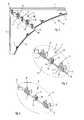
- FIG. 1 an inventive wall ring is shown.
- This consists of a support frame 1, on which a round-shaped nozzle 2 is attached via form and adhesion-connection elements 3.
- the support frame 1 comprises a circular opening 4.
- the support frame 1 in turn is composed of several frame members 6 connected to each other via form and force-locking connection elements 5. It is advantageous if the support frame 1 has a rectangular, in particular square outline contour, so that it has four in particular equal length frame edges 7 and four corners 8.
- each frame member 6 has lateral connection side edges 10, which coincide in the assembled state with the diagonals d1 and d2 and coincide with the Frame edges 7 include an angle of 45 °.
- the diameter of the opening 4 and the inner diameter of the ronde-shaped nozzle 2 are adapted to the diameter of a blade wheel of an axial fan to be mounted in a known manner. Furthermore, it can be seen that in the corner regions of the support frame 1 holes 33 are formed, are passed through the fasteners when the support frame 1 is attached to a housing wall or the like.
- the connecting elements 5 are provided, which consist of locking elements 11, 12 and guide elements 13, 14, so that the frame members 6 can be positively and non-positively connected to each other.
- the latching elements are formed as latching tongues 11 on a connection side edge 10 of a frame element 6 and cooperate with latching receptacles 12 which are formed on the connection side edge 10 of the other, adjacent frame element 6.
- the locking tongues 11 have a central opening 15, engage in the locking cam 16 of the locking receptacles 12 in the assembled state, wherein the locking tongues 11 between Both sides of the locking cam 16 integrally formed limiting projections 17 are performed.
- the pin receptacles 14 have a one-sided open-edged passage opening 18.
- the guide pin 13 has a guide extension 19, which passes through the open-edge region of the passage opening 18, so that a positive and frictional connection between the guide extension 19 and pin receptacle 14 is formed.
- the 4 and 5 show the inventive design of the connecting elements 11, 12 and guide elements 13, 14th
- two identical frame elements 6 result twice per support frame 1.
- Another advantage is that this design results in a simple storage of stock and the transport volume is very low.
- the frame elements 6 have in the region of their arcuate boundary edge 9 a plurality of perpendicular to its surface extending locking tongues 11, which cooperate with matched locking receptacles 12 on the circular-shaped nozzle 2.
- These latching tongues 11 and latching receptacles 12 are formed corresponding to the connecting elements 11, 12 on the connection side edges 10, and also on the frame elements 6 in the region of the boundary edges 9.
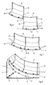
- the round-shaped nozzle 2 consists of a cylindrical portion 20 and an extending between this and the support frame 1, in the axial direction of its central longitudinal axis XX arcuately curved annular transition portion 21, so that there is a nozzle-shaped contour.
- the ronde-shaped nozzle 2 is composed of several Ronde segments 22.
- at least eight blank segments 22 are used, resulting in a 45 ° pitch.
- the nozzle 2 consists of twelve individual Ronde segments 22, so that a 30 ° pitch exists is, which are connected to each other at their juxtaposed side edges 23, 24 in the region of the cylindrical portion 20 via connecting elements 25, 26.
- the connecting elements 25, 26 consist of parallel to the side edge 23 extending, outwardly projecting guide rails 25 which can be inserted into a guide groove of a cross-sectionally U-shaped guide rail 26 on the side edge 24 of the adjacent Ronde segment 22.
- Guiding elements 29, 30 are formed in the region of the transitional section 21, specifically on the adjacent side edges 23, 24, wherein the guide elements of the side edge 23 are formed of guide pins 29 and the corresponding guide elements on the side edge 24 are formed of pin holders 30. These guide elements 29, 30 may be formed again corresponding to the guide elements 13, 14.
- the Ronde segments 22 have at the free end of their transition portion 21 on a circular arc-shaped side edge 31, which belongs to an end-side flat contact portion 32 with which the Ronde segment 22 rests on the support frame 1 in the edge region of the opening 4.
- the locking receptacles 12 are formed on its side facing away from the support frame 1 side, which form a positive and non-positive connection with the locking tongues 11.
- the round blank segments 22 according to the invention are all of identical construction, so that they can be manufactured with the same tool, for example by injection molding or vacuum drawing, which on the one hand, the manufacturing costs are low and on the other hand, a cost storage or storage results, and the transport costs can be significantly reduced.
- the support frame 1 and the round-shaped nozzle 2 are first assembled from their individual frame elements 6 and Ronde segments 22, respectively then firmly connected to each other via the existing connection and guide elements 11, 12, 13, 14 and 25, 26, 29, 30, so that there is a closed, stable wall ring, see also Fig. 1 ,
- the frame members 6 to be joined are aligned at their contact sides with a small height offset, so that the locking tongues 11 are arranged below the locking receptacles 12 and the guide pins 13 are below the respective pin receptacles 14. Then, the connecting elements 11, 12 and the guide elements 13, 14 are pushed into each other and so made the connection.
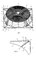
- Fig. 9 It is shown how an axial fan 41 is fixed by means of support struts 42 on the support frame 1.
- the support struts 42 are screwed by screws 43 on the support frame 1 by 1 screw inserts 34 are provided in the support frame, into which the screws 43 are screwed.
- the frame members 6 and the Ronde segments 22 are made of plastic, namely advantageously made of polypropylene, which is in particular glass fiber reinforced, and are produced as injection molded parts or by vacuum drawing.
- Fig. 10 is one of the Fig. 3 corresponding partial view of another embodiment of a support frame 1 according to the invention shown.
- the frame elements 6 made of metal sheet blanks formed in their shape the frame elements 6, as to the Fig. 1-9 described, can correspond.
- the connecting tab (n ) Is bent by a measure corresponding to the thickness of the blanks, so that the frame members 6 are aligned with each other and lie in the same plane.
- connection 36 extending through the connecting strap (s) 35 and the respectively covered frame element 6 are provided for the mutual connection of the frame elements 6. But it can also be a connection by welding or cold deformation.
- the screw or rivet connections are then provided on the blank segments 22 in the region of the contact section 32. Also, in this area, a connection can be made by welding or cold working.
- the invention is not limited to the illustrated and described embodiments, but also includes all the same in the context of the invention embodiments. Furthermore, the invention is so far not yet limited to the feature combination defined in claim 1, but may also be defined by any other combination of certain features of all individually disclosed individual features. This means that in principle virtually every individual feature of claim 1 can be omitted or replaced by at least one individual feature disclosed elsewhere in the application. In this respect, the claim 1 is to be understood only as a first formulation attempt for an invention.
Abstract
Description
Die vorliegende Erfindung betrifft einen Wandring für einen Axialventilator, bestehend aus einem Tragrahmen, an dem ein rondenförmiger Stutzen ausgebildet ist, in dem der Axialventilator angeordnet wird.The present invention relates to a wall ring for an axial fan, consisting of a support frame, on which a Ronde-shaped socket is formed, in which the axial fan is arranged.
Derartige, ein einstückiges Bauteil bildende Wandringe benötigen einerseits viel Lagerraum und andererseits auch ein erhebliches Transportvolumen und sind in der Fertigung auf Grund der aufwändigen Werkzeuge, die zum Spritzgießen der beispielsweise aus Kunststoff bestehenden Wandringe erforderlich sind, teuer in der Herstellung.Such, one-piece component forming wall rings need on the one hand a lot of storage space and on the other hand, a considerable transport volume and are expensive to manufacture due to the complex tools that are required for injection molding of plastic, for example, existing wall rings, expensive to manufacture.
Der vorliegenden Erfindung liegt die Aufgabe zu Grunde, einen Wandring der eingangs beschriebenen Art zu schaffen, dessen Herstellung durch die Verwendung einfacher Spritzwerkzeuge kostengünstiger ist und der einen geringeren Platzbedarf bei der Lagerung und beim Transport aufweist.The present invention is based on the object to provide a wall ring of the type described above, whose production is cheaper by the use of simple injection molds and has a smaller footprint in storage and during transport.
Erfindungsgemäß wird dies dadurch erreicht, dass der Tragrahmen aus mehreren Rahmenelementen mittels form- und kraftschlüssiger Verbindungselemente zusammengesetzt ist und der rondenförmige Stutzen aus mehreren umfangsgemäß hintereinander angeordneten Rondensegmenten gebildet ist, die durch form- und kraftschlüssige Verbindungen miteinander und mit dem Tragrahmen verbunden sind.According to the invention this is achieved in that the support frame is composed of a plurality of frame members by means of positive and non-positive fasteners and the Ronde-shaped nozzle is formed from a plurality circumferentially arranged behind one another Ronde segments, which are connected by positive and non-positive connections with each other and with the support frame.
Hierbei ist es insbesondere vorteilhaft, wenn der Tragrahmen aus vier Rahmenelementen zusammengesetzt ist und der rondenförmige Stutzen aus mindestens acht, vorzugsweise zwölf Segmenten zusammengefügt wird, so dass die Segmente eine 45 ° Teilung bzw. eine 30 ° Teilung des rondenförmigen Stutzens bedingen. Dabei ist es insbesondere vorteilhaft, wenn der Tragrahmen eine rechteckförmige, insbesondere quadratische Umfangskontur mit vier Ecken und eine zentrische Öffnung besitzt, wobei vier verbreiterte Eckbereiche ausgebildet sind und die Rahmenelemente durch eine Teilung gemäß den beiden durch die Ecken verlaufenden Diagonalen gebildet sind.It is particularly advantageous if the support frame is composed of four frame elements and the round-shaped nozzle is assembled from at least eight, preferably twelve segments, so that the segments cause a 45 ° pitch or a 30 ° pitch of the Ronde-shaped neck. It is particularly advantageous if the support frame has a rectangular, in particular square peripheral contour with four corners and a central opening, wherein four widened corner regions are formed and the frame members are formed by a division according to the two extending through the corners diagonals.
Durch die Unterteilung des Tragrahmens in einzelne Rahmenelemente und die Unterteilung des rondenförmigen Stutzens in mehrere Rondensegmente ergibt sich eine sehr raumsparende Lagerung und ein geringes Transportvolumen, da die einzelnen Segmente zu Segmentpaketen zusammengefasst werden können und die Zusammensetzung des erfindungsgemäßen Wandrings erst vor dem Einbau des Axialventilators erfolgt. Durch die erfindungsgemäßen form- und kraftschlüssigen Verbindungen der einzelnen Elemente bzw. Segmente miteinander und untereinander ergibt sich einerseits ein einfaches Zusammensetzen der Einzelteile und darüberhinaus eine sehr robuste Verbindung, die die erforderlichen Haltekräfte aufnehmen kann.By dividing the support frame into individual frame elements and the subdivision of the Ronde-shaped nozzle into a plurality Ronde segments results in a very space-saving storage and a low transport volume, since the individual segments can be combined into segment packets and the composition of the wall ring according to the invention takes place only before the installation of the axial fan , Due to the positive and non-positive connections of the individual elements or segments according to the invention with each other and with each other, on the one hand a simple assembly of the items and beyond a very robust connection that can accommodate the required holding forces.
Vorteilhafte Ausführungen der Erfindung sind in den Unteransprüchen enthalten und werden an Hand des in den beiliegenden Zeichnungen dargestellten Ausführungsbeispiels näher erläutert. Es zeigen:
- Fig. 1
- eine perspektivische Ansicht eines erfindungsgemäßen Wandrings,
- Fig. 2
- eine Ansicht eines erfindungsgemäßen Tragrahmens,
- Fig. 3
- eine Teilansicht des erfindungsgemäßen Tragrahmens gemäß
Fig. 2 vor dem Zusammenfügen der Rahmenelemente, - Fig. 4
- eine Teilansicht gemäß IV in
Fig. 3 , - Fig. 5
- eine Ansicht entsprechend der Teilansicht gemäß
Fig. 4 , jedoch im zusammengesetzten Zustand der Rahmenelemente, - Fig. 6
- eine Ansicht von zwei Rondensegmenten gemäß der Erfindung vor dem Zusammenfügen,
- Fig. 7
- eine Ansicht zweier Rondensegmente nach dem Zusammenfügen,
- Fig. 8
- eine Teilansicht zweier zusammengefügter Rahmenelemente und zweier zusammengefügter Rondensegmente vor der Verbindung zwischen dem Tragrahmen und dem rondenförmigen Stutzen,
- Fig. 9
- eine perspektivische Ansicht eines erfindungsgemäßen Wandrings mit in diesem angeordnetem Axialventilator
- Fig. 10
- eine Teilansicht einer weiteren erfindungsgemäßen Ausführung des Tragrahmens.
- Fig. 1
- a perspective view of a wall ring according to the invention,
- Fig. 2
- a view of a support frame according to the invention,
- Fig. 3
- a partial view of the support frame according to the invention according to
Fig. 2 before assembling the frame elements, - Fig. 4
- a partial view according to IV in
Fig. 3 . - Fig. 5
- a view according to the partial view according to
Fig. 4 but in the assembled state of the frame elements, - Fig. 6
- a view of two Ronde segments according to the invention prior to assembly,
- Fig. 7
- a view of two blank segments after joining,
- Fig. 8
- a partial view of two assembled frame members and two assembled Ronde segments before the connection between the support frame and the Ronde-shaped nozzle,
- Fig. 9
- a perspective view of a wall ring according to the invention with arranged in this axial fan
- Fig. 10
- a partial view of another embodiment of the support frame according to the invention.
In den
In
Im Randbereich der Verbindungsseitenkanten 10 sind die Verbindungselemente 5 vorgesehen, die aus Rastelementen 11, 12 und Führungselementen 13, 14 bestehen, so dass die Rahmenelemente 6 form- und kraftschlüssig miteinander verbunden werden können. Die Rastelemente sind als Rastzungen 11 an einer Verbindungsseitenkante 10 eines Rahmenelementes 6 ausgebildet und wirken mit Rastaufnahmen 12 zusammen, die an der Verbindungsseitenkante 10 des anderen, angrenzenden Rahmenelementes 6 ausgebildet sind. Entsprechendes gilt für die Führungselemente 13, 14, die als Führungszapfen 13 des einen Rahmenelementes 6 im Bereich seiner Verbindungsseitenkante 10 mit zugehörigen Zapfenaufnahmen 14 an der Verbindungsseitenkante 10 des anderen Rahmenelementes 6 zusammenwirken. Die Rastzungen 11 weisen eine mittlere Öffnung 15 auf, in die Rastnocken 16 der Rastaufnahmen 12 im zusammengefügten Zustand einrasten, wobei die Rastzungen 11 zwischen beidseitig des Rastnockens 16 angeformten Begrenzungsvorsprüngen 17 geführt werden. Die Zapfenaufnahmen 14 weisen eine einseitig randoffene Durchgangsöffnung 18 auf. Der Führungszapfen 13 besitzt einen Führungsfortsatz 19, der durch den randoffenen Bereich der Durchgangsöffnung 18 verläuft, so das eine Form- und Kraftschlussverbindung zwischen Führungsfortsatz 19 und Zapfenaufnahme 14 entsteht.In the edge region of the
Die
Erfindungsgemäß sind somit die Rahmenelemente 6, insbesondere bei der quadratischen Ausführung, alle baugleich ausgeführt und können mit demselben Formwerkzeug, beispielsweise im Spritzgussverfahren hergestellt werden. Bei rechteckförmiger Ausführung ergeben sich pro Tragrahmen 1 zweimal zwei gleiche Rahmenelemente 6. Ein weiterer Vorteil besteht darin, dass sich durch diese Ausgestaltung eine einfache Lagerbevorratung ergibt und das Transportvolumen sehr gering ist. Weiterhin besitzen die Rahmenelemente 6 im Bereich ihrer kreisbogenförmigen Begrenzungskante 9 mehrere senkrecht zu ihrer Oberfläche verlaufende Rastzungen 11, die mit angepassten Rastaufnahmen 12 an dem rondenförmigen Stutzen 2 zusammenwirken. Diese Rastzungen 11 und Rastaufnahmen 12 sind entsprechend den Verbindungselementen 11, 12 an den Verbindungsseitenkanten 10, auch an den Rahmenelementen 6 im Bereich der Begrenzungskanten 9 ausgebildet. Der rondenförmige Stutzen 2 besteht aus einem zylinderförmigen Abschnitt 20 sowie einem zwischen diesem und dem Tragrahmen 1 verlaufenden, in axialer Richtung seiner mittleren Längsachse X-X bogenförmig gekrümmten, ringförmigen Übergangsabschnitt 21, so dass sich eine düsenförmige Kontur ergibt. Erfindungsgemäß ist der rondenförmige Stutzen 2 aus mehreren Rondensegmenten 22 zusammengefügt. Vorteilhafterweise werden mindestens acht Rondensegmente 22 verwendet, so dass sich eine 45 ° Teilung ergibt. Im dargestellten bevorzugten Ausführungsbeispiel besteht der Stutzen 2 aus zwölf einzelnen Rondensegmenten 22, so dass eine 30 ° Teilung vorhanden ist, die an ihren aneinander liegenden Seitenkanten 23, 24 im Bereich des zylinderförmigen Abschnitts 20 jeweils über Verbindungselemente 25, 26 miteinander verbunden werden. Die Verbindungselemente 25, 26 bestehen aus parallel zur Seitenkante 23 verlaufende, nach außen abstehende Führungsleisten 25, die in eine Führungsnut einer im Querschnitt U-förmigen Führungsschiene 26 an der Seitenkante 24 des angrenzenden Rondensegmentes 22 eingeschoben werden kann. Im Bereich des Übergangsabschnitts 21 sind Führungselemente 29, 30 ausgebildet, und zwar an den angrenzenden Seitenkanten 23, 24, wobei die Führungselemente der Seitenkante 23 aus Führungszapfen 29 und die korrespondierenden Führungselemente an der Seitenkante 24 aus Zapfenaufnahmen 30 gebildet sind. Diese Führungselemente 29, 30 können wieder entsprechend den Führungselementen 13, 14 ausgebildet sein.According to the invention, therefore, the
Die Rondensegmente 22 weisen am freien Ende ihres Übergangsabschnittes 21 eine kreisbogenförmige Seitenkante 31 auf, die zu einem endseitigen flachen Anlageabschnitt 32 gehört, mit dem das Rondensegment 22 auf dem Tragrahmen 1 im Randbereich der Öffnung 4 aufliegt. Auf diesem Anlageabschnitt 32 sind auf seiner von dem Tragrahmen 1 abgekehrten Seite die Rastaufnahmen 12 ausgebildet, die mit den Rastzungen 11 eine form- und kraftschlüssige Verbindung eingehen.The
Die erfindungsgemäßen Rondensegmente 22 sind alle baugleich ausgeführt, so dass sie mit demselben Werkzeug beispielsweise durch Spritzgießen oder Vakuumziehen hergestellt werden können, wodurch einerseits die Herstellkosten niedrig sind und andererseits sich eine kostengünstige Bevorratung bzw. Lagerhaltung ergibt, und auch die Transportkosten wesentlich reduziert werden können.The round
Zur Montage des erfindungsgemäßen Wandrings werden zunächst der Tragrahmen 1 und der rondenförmige Stutzen 2 aus ihren einzelnen Rahmenelementen 6 bzw. Rondensegmenten 22 jeweils zusammengefügt und dann über die bestehenden Verbindungs- und Führungselemente 11, 12, 13, 14 bzw. 25, 26, 29, 30 miteinander fest verbunden, so dass sich ein geschlossener, stabiler Wandring ergibt, siehe hierzu auch
In
In
An Stelle der zu den in den
Die Erfindung ist nicht auf die dargestellten und beschriebenen Ausführungsbeispiele beschränkt, sondern umfasst auch alle im Sinne der Erfindung gleichwirkenden Ausführungen. Ferner ist die Erfindung bislang auch noch nicht auf die im Anspruch 1 definierte Merkmalskombination beschränkt, sondern kann auch durch jede beliebige andere Kombination von bestimmten Merkmalen aller insgesamt offenbarten Einzelmerkmalen definiert sein. Dies bedeutet, dass grundsätzlich praktisch jedes Einzelmerkmal des Anspruchs 1 weggelassen bzw. durch mindestens ein an anderer Stelle der Anmeldung offenbartes Einzelmerkmal ersetzt werden kann. Insofern ist der Anspruch 1 lediglich als ein erster Formulierungsversuch für eine Erfindung zu verstehen.The invention is not limited to the illustrated and described embodiments, but also includes all the same in the context of the invention embodiments. Furthermore, the invention is so far not yet limited to the feature combination defined in
Claims (18)
dadurch gekennzeichnet, dass der Tragrahmen (1) aus mehreren Rahmenelementen (6) mittels form- und kraftschlüssiger Verbindungselementen (11, 12, 35, 36) zusammengesetzt ist und der rondenförmige Stutzen (2) aus mehreren umfangsgemäß hintereinander angeordneten Rondensegmenten (22) gebildet ist, die durch form- und kraftschlüssige oder materialschlüssige Verbindungen bzw. Verbindungselemente (25, 26, 35, 36) miteinander und mit dem Tragrahmen (1) verbunden sind.Wall ring for an axial fan, consisting of a support frame (1) on which a ronde-shaped connecting piece (2) is formed, in which the axial fan is arranged,
characterized in that the support frame (1) of a plurality of frame members (6) by means of positive and non-positive connection elements (11, 12, 35, 36) is composed and the Ronde-shaped socket (2) from a plurality of circumferentially arranged successively Ronde segments (22) is formed , which are connected by positive and non-positive or material-locking connections or connecting elements (25, 26, 35, 36) with each other and with the support frame (1).
dadurch gekennzeichnet, dass der Tragrahmen (1) eine rechteckige, insbesondere quadratische Umfangskontur (7) mit vier Ecken (8) sowie eine zentrische Öffnung (15) besitzt, wobei vier verbreiterte Eckbereiche ausgestaltet sind, und die Rahmenelemente (6) durch eine Teilung entlang von durch die Ecken des Tragrahmens (1) verlaufenden Diagonalen (d1, d2) gebildet sind.Wall ring according to claim 1,
characterized in that the support frame (1) has a rectangular, in particular square circumferential contour (7) with four corners (8) and a central opening (15), wherein four widened corner regions are configured, and the frame members (6) along a division from extending through the corners of the support frame (1) diagonals (d1, d2) are formed.
dadurch gekennzeichnet, dass der rondenförmige Stutzen (2) aus einem zylinderförmigen Abschnitt (20) sowie einem zwischen diesem und dem Tragrahmen (1) verlaufenden in Achsrichtung seiner Längsachse (X-X) bogenförmig gekrümmten, ringförmigen Übergangsabschnitt (21) besteht.Wall ring according to claim 1 or 2,
characterized in that the ronde-shaped connecting piece (2) consists of a cylindrical portion (20) and between this and the support frame (1) extending in the axial direction of its longitudinal axis (XX) arcuately curved annular transition portion (21).
dadurch gekennzeichnet, dass der rondenförmige Stutzen (2) aus zwölf Rondensegmenten (22) zusammengesetzt ist.Wall ring according to one of claims 1 to 3,
characterized in that the ronde-shaped connecting piece (2) is composed of twelve round blank segments (22).
dadurch gekennzeichnet, dass die Rahmenelemente (6) und die Rondensegmenten (22) zusätzlich zu den Verbindungselementen (11, 12 und 25, 26, 35, 36) Führungselemente (13, 14 und 29, 30) zur gegenseitigen Führung aufweisen.Wall ring according to one of claims 1 to 4,
characterized in that the frame members (6) and the blanking segments (22) in addition to the connecting elements (11, 12 and 25, 26, 35, 36) guide elements (13, 14 and 29, 30) for mutual guidance.
dadurch gekennzeichnet, dass die Rahmenelemente (6) untereinander baugleich sind, und die Rondensegmente (22) ebenfalls untereinander baugleich ausgebildet sind.Wall ring according to one of claims 1 to 5,
characterized in that the frame elements (6) are identical to each other, and the Ronde segments (22) are also constructed identical to each other.
dadurch gekennzeichnet, dass die Verbindungselemente (11, 12) aus Rastzungen (11) an einer Verbindungsseitenkante (10) eines Rahmenelementes (6) und aus Rastaufnahmen (12) an der Verbindungsseitenkante (10) des anderen angrenzenden Rahmenelementes (6) ausgebildet sind.Wall ring according to one of claims 1 to 6,
characterized in that the connecting elements (11, 12) of locking tongues (11) on a connection side edge (10) of a frame element (6) and from latching receptacles (12) on the connection side edge (10) of the other adjacent frame element (6) are formed.
dadurch gekennzeichnet, dass die Rahmenelemente (6) im Randbereich ihrer Verbindungsseitenkanten (10) Führungselemente aus Führungszapfen (13) und zugehörigen Zapfenaufnahmen (14) aufweisen, wobei die Führungszapfen (13) des einen Rahmenelementes (6) im Bereich seiner Verbindungsseitenkante (10) und die Zapfenaufnahmen (14) an der Verbindungsseitenkante (10) des anderen Rahmenelementes (6) ausgebildet sind.Wall ring according to one of claims 1 to 7,
characterized in that the frame elements (6) in the edge region of their connection side edges (10) guide elements of guide pins (13) and associated pin receptacles (14), wherein the guide pins (13) of a frame member (6) in the region of its connection side edge (10) and the pin receivers (14) are formed on the connecting side edge (10) of the other frame element (6).
dadurch gekennzeichnet, dass die Rastzungen (11) eine mittlere Öffnung (15) aufweisen, in die Rastnocken (16) der Rastaufnahme (12) im zusammengefügten Zustand einrasten.Wall ring according to one of claims 1 to 8,
characterized in that the latching tongues (11) have a central opening (15), in the latching cams (16) of the latching receptacle (12) engage in the assembled state.
dadurch gekennzeichnet, dass die Rondensegmente (22) am freien Ende ihres Übergangsabschnitts (21) eine kreisbogenförmige Seitenkante (31) besitzen, die zu einem endseitig flachen Anlageabschnitt (32) gehört, mit dem das Rondensegment (22) auf dem Tragrahmen (1) im Randbereich der Öffnung (4) aufliegt.Wall ring according to one of claims 1 to 9,
characterized in that the Ronde segments (22) at the free end of their transition section (21) have a circular arc-shaped side edge (31) belonging to an end flat contact portion (32), with the Ronde segment (22) on the support frame (1) in Edge region of the opening (4) rests.
dadurch gekennzeichnet, dass die Verbindungselemente (25, 26) der Rondensegmente (22) aus parallel zur Seitenkante (23) verlaufenden, nach außen abstehenden Führungsleisten (25) bestehen, die in eine Führungsnut einer im Querschnitt U-förmigen Führungsschiene (26) an der Seitenkante des angrenzenden Rondensegments (22) eingeschoben sind.Wall ring according to one of claims 1 to 10,
characterized in that the connecting elements (25, 26) of the Ronde segments (22) from parallel to the side edge (23) extending, outwardly projecting guide rails (25) consist in a guide groove in cross-sectionally U-shaped guide rail (26) on the Side edge of the adjacent Ronde segment (22) are inserted.
dadurch gekennzeichnet, dass die Rahmenelemente (6) im Bereich ihrer kreisbogenförmigen Begrenzungskante (9) mehrere, senkrecht zu ihrer Oberfläche verlaufende Rastzungen (11) aufweisen, die mit angepassten Rastaufnahmen (12) an dem rondenförmigen Stutzen (2) zusammenwirken.Wall ring according to one of claims 1 to 11,
characterized in that the frame elements (6) in the region of their arcuate boundary edge (9) have a plurality of perpendicular to its surface extending locking tongues (11) which cooperate with adapted latching receptacles (12) on the Ronde-shaped nozzle (2).
dadurch gekennzeichnet, dass auf dem Anlageabschnitt (32) auf seiner von dem Tragrahmen (1) abgekehrten Seite die Rastaufnahmen (12) ausgebildet sind, die mit den Rastzungen (11) zusammenwirken.Wall ring according to claim 12,
characterized in that on the contact portion (32) on its side facing away from the support frame (1) side, the locking receptacles (12) are formed, which cooperate with the locking tongues (11).
dadurch gekennzeichnet, dass im Bereich des Übergangsabschnitts (21) Führungselemente (29, 30) ausgebildet sind, und zwar an den angrenzenden Seitenkanten (23, 24), wobei die Elemente der Seitenkante (23) aus Führungszapfen (29), und die korrespondierenden Führungselemente an der anderen Seitenkante (24) aus Zapfenaufnahmen (30) bestehen.Wall ring according to one of claims 11 to 13,
characterized in that in the region of the transition portion (21) guide elements (29, 30) are formed, to the adjacent side edges (23, 24), wherein the elements of the side edge (23) of guide pins (29), and the corresponding guide elements on the other side edge (24) consist of pin receptacles (30).
dadurch gekennzeichnet, dass die Rahmenelemente (6) und die Rondensegmente (22) aus Kunststoff, insbesondere aus Polypropylen, durch Spritzgießen oder Vakuumziehen hergestellt sind.Wall ring according to one of claims 1 to 14,
characterized in that the frame elements (6) and the Ronde segments (22) made of plastic, in particular of polypropylene, are produced by injection molding or vacuum drawing.
dadurch gekennzeichnet, dass zur Verbindung der Rahmenelemente (6) miteinander im Bereich der Verbindungsseitenkanten (10) das eine Rahmenelement (6) eine oder mehrere Verbindungslaschen (35) aufweist, die das andere Rahmenelement (6) überdeckt bzw. überdecken und im Überdeckungsbereich die Verbindung zwischen den Rahmenelementen (6) durch Schraub- oder Nietverbindungen (36) oder durch Verschweißen oder Kaltverformung erfolgt.Wall ring according to one of claims 1 to 11,
characterized in that for the connection of the frame elements (6) in the region of the connection side edges (10), the one frame element (6) has one or more connecting straps (35) covering or covering the other frame element (6) and the connection in the covering area between the frame members (6) by screw or rivet connections (36) or by welding or cold deformation.
dadurch gekennzeichnet, dass die Rahmenelemente (6) und die Rondensegmente (22) im Bereich des Anlageabschnittes (32) durch Schraub- oder Nietverbindungen (36) oder durch Verschweißen oder Kaltverformung verbunden sind.Wall ring according to one of claims 1 to 11 and 16,
characterized in that the frame elements (6) and the Ronde segments (22) in the region of the abutment portion (32) by screw or rivet connections (36) or by welding or cold deformation are connected.
dadurch gekennzeichnet, dass die Rahmenelemente (6) und/oder die Rondensegmenten (22) aus Metallblech-Zuschnitten bestehen.Wall ring according to claim 16 or 17,
characterized in that the frame elements (6) and / or the Ronde segments (22) consist of sheet metal blanks.
Priority Applications (5)
| Application Number | Priority Date | Filing Date | Title |
|---|---|---|---|
| ES11173522T ES2444142T3 (en) | 2011-07-12 | 2011-07-12 | Wall ring for an axial fan |
| EP20110173522 EP2546528B1 (en) | 2011-07-12 | 2011-07-12 | Wall ring for an axial ventilator |
| PT11173522T PT2546528E (en) | 2011-07-12 | 2011-07-12 | Wall ring for an axial ventilator |
| US13/493,271 US9074611B2 (en) | 2011-07-12 | 2012-06-11 | Wall ring for axial fan |
| CN201210203723.2A CN102878103B (en) | 2011-07-12 | 2012-06-15 | The wall ring of axial fan |
Applications Claiming Priority (1)
| Application Number | Priority Date | Filing Date | Title |
|---|---|---|---|
| EP20110173522 EP2546528B1 (en) | 2011-07-12 | 2011-07-12 | Wall ring for an axial ventilator |
Publications (2)
| Publication Number | Publication Date |
|---|---|
| EP2546528A1 true EP2546528A1 (en) | 2013-01-16 |
| EP2546528B1 EP2546528B1 (en) | 2013-12-25 |
Family
ID=44533849
Family Applications (1)
| Application Number | Title | Priority Date | Filing Date |
|---|---|---|---|
| EP20110173522 Active EP2546528B1 (en) | 2011-07-12 | 2011-07-12 | Wall ring for an axial ventilator |
Country Status (5)
| Country | Link |
|---|---|
| US (1) | US9074611B2 (en) |
| EP (1) | EP2546528B1 (en) |
| CN (1) | CN102878103B (en) |
| ES (1) | ES2444142T3 (en) |
| PT (1) | PT2546528E (en) |
Cited By (3)
| Publication number | Priority date | Publication date | Assignee | Title |
|---|---|---|---|---|
| DE202013100139U1 (en) * | 2013-01-11 | 2014-04-15 | Ebm-Papst Mulfingen Gmbh & Co. Kg | Composite of a protective grid and a wall ring and fan with such a composite |
| DE102018128824A1 (en) * | 2018-11-16 | 2020-05-20 | Ebm-Papst Mulfingen Gmbh & Co. Kg | Diagonal fan with housing |
| WO2021013497A1 (en) * | 2019-07-19 | 2021-01-28 | Ebm-Papst Mulfingen Gmbh & Co. Kg | Housing ring of an axial ventilator |
Families Citing this family (8)
| Publication number | Priority date | Publication date | Assignee | Title |
|---|---|---|---|---|
| USD728090S1 (en) * | 2012-10-11 | 2015-04-28 | Ebm-Papst Mulfingen Gmbh & Co. Kg | Electric fan |
| US9835176B2 (en) | 2013-04-05 | 2017-12-05 | Acoustiflo Llc | Fan inlet air handling apparatus and methods |
| USD771228S1 (en) * | 2013-12-30 | 2016-11-08 | Ebm-Papst Mulfingen Gmbh & Co. Kg | Fan |
| USD764652S1 (en) * | 2014-01-06 | 2016-08-23 | Ebm-Papst Mulfingen Gmbh & Co. Kg | Diffuser grid |
| USD775321S1 (en) * | 2014-08-25 | 2016-12-27 | Ebm-Papst Mulfingen Gmbh & Co. Kg | Ventilation grid |
| USD761412S1 (en) * | 2014-11-04 | 2016-07-12 | Ebm-Papst Mulfingen Gmbh & Co. Kg | Fan grid |
| CN108443180A (en) * | 2018-04-12 | 2018-08-24 | 中山威峰通风设备有限公司 | A kind of draft fan |
| US20240052851A1 (en) * | 2022-08-15 | 2024-02-15 | Delta Electronics, Inc. | Fan housing |
Citations (5)
| Publication number | Priority date | Publication date | Assignee | Title |
|---|---|---|---|---|
| US4018297A (en) * | 1975-11-03 | 1977-04-19 | Allis-Chalmers Corporation | Four-piece fan shroud |
| US4522160A (en) * | 1984-01-23 | 1985-06-11 | J. I. Case Company | Fan-shroud structure |
| US4741669A (en) * | 1983-04-27 | 1988-05-03 | Tatsuji Shimokawabe | Shroud |
| US20110067845A1 (en) * | 2009-04-13 | 2011-03-24 | Alan Bishop | Fan shroud assembly |
| WO2011044909A1 (en) * | 2009-10-13 | 2011-04-21 | Novenco A/S | An axial fan and a method of manufacturing a blower pi pe therefor |
Family Cites Families (5)
| Publication number | Priority date | Publication date | Assignee | Title |
|---|---|---|---|---|
| NL1014013C2 (en) * | 2000-01-05 | 2001-07-18 | Ventilatoren Sirocco Howden Bv | Housing part for a fan impeller. |
| US7086825B2 (en) * | 2004-09-24 | 2006-08-08 | Carrier Corporation | Fan |
| US20060081353A1 (en) * | 2004-10-19 | 2006-04-20 | Inniger Steven W | Split access fan shroud |
| CN201013669Y (en) * | 2007-02-28 | 2008-01-30 | 沃斯特曼斯通风有限公司 | Ventilating fan |
| CN201318327Y (en) * | 2008-11-11 | 2009-09-30 | 哈尔滨空调股份有限公司 | Fan drum device of large axial-flow fan |
-
2011
- 2011-07-12 ES ES11173522T patent/ES2444142T3/en active Active
- 2011-07-12 EP EP20110173522 patent/EP2546528B1/en active Active
- 2011-07-12 PT PT11173522T patent/PT2546528E/en unknown
-
2012
- 2012-06-11 US US13/493,271 patent/US9074611B2/en not_active Expired - Fee Related
- 2012-06-15 CN CN201210203723.2A patent/CN102878103B/en active Active
Patent Citations (5)
| Publication number | Priority date | Publication date | Assignee | Title |
|---|---|---|---|---|
| US4018297A (en) * | 1975-11-03 | 1977-04-19 | Allis-Chalmers Corporation | Four-piece fan shroud |
| US4741669A (en) * | 1983-04-27 | 1988-05-03 | Tatsuji Shimokawabe | Shroud |
| US4522160A (en) * | 1984-01-23 | 1985-06-11 | J. I. Case Company | Fan-shroud structure |
| US20110067845A1 (en) * | 2009-04-13 | 2011-03-24 | Alan Bishop | Fan shroud assembly |
| WO2011044909A1 (en) * | 2009-10-13 | 2011-04-21 | Novenco A/S | An axial fan and a method of manufacturing a blower pi pe therefor |
Cited By (3)
| Publication number | Priority date | Publication date | Assignee | Title |
|---|---|---|---|---|
| DE202013100139U1 (en) * | 2013-01-11 | 2014-04-15 | Ebm-Papst Mulfingen Gmbh & Co. Kg | Composite of a protective grid and a wall ring and fan with such a composite |
| DE102018128824A1 (en) * | 2018-11-16 | 2020-05-20 | Ebm-Papst Mulfingen Gmbh & Co. Kg | Diagonal fan with housing |
| WO2021013497A1 (en) * | 2019-07-19 | 2021-01-28 | Ebm-Papst Mulfingen Gmbh & Co. Kg | Housing ring of an axial ventilator |
Also Published As
| Publication number | Publication date |
|---|---|
| CN102878103B (en) | 2016-09-14 |
| EP2546528B1 (en) | 2013-12-25 |
| US9074611B2 (en) | 2015-07-07 |
| US20130017073A1 (en) | 2013-01-17 |
| ES2444142T3 (en) | 2014-02-24 |
| PT2546528E (en) | 2014-01-07 |
| CN102878103A (en) | 2013-01-16 |
Similar Documents
| Publication | Publication Date | Title |
|---|---|---|
| EP2546528B1 (en) | Wall ring for an axial ventilator | |
| EP2610506B1 (en) | Spring nut | |
| EP2952439B1 (en) | Carrier assembly | |
| EP0705649B1 (en) | Method for manufacturing a flat or centripetal screen | |
| EP2860127B1 (en) | Device for holding objects and corresponding connecting device | |
| EP0384153A2 (en) | Supporting chain for energy carrier | |
| DE102011009091A1 (en) | Coil for receiving winding material and coil subsystem | |
| EP2570234B1 (en) | Carrier | |
| DE102014215986A1 (en) | Track broadening system for motor vehicles | |
| EP0515657A1 (en) | Combined radial/axial friction bearing and method of manufacturing it. | |
| EP3656252B1 (en) | Chair | |
| EP1181463A1 (en) | Assembled flange-bearing shell | |
| EP3110587A1 (en) | Soldering tip fastening system | |
| EP1441081B1 (en) | Connector for profiles and connector assembly | |
| DE202013100387U1 (en) | threaded fastener | |
| DE602004007292T2 (en) | ARRANGEMENT FOR SOLDERABLE ATTACHMENT OF A RECKSTANGE TO A SLIDER | |
| EP3064857B1 (en) | Device hood | |
| EP3353000B1 (en) | Housing connecting device for connecting housing sections or housing modules of ventilation or air-conditioning systems | |
| EP3030379B1 (en) | Clamping claw for a tensioning device | |
| EP2660411B1 (en) | Key bow cover | |
| EP0549816A1 (en) | Grid rod for the construction of a grid | |
| DE102016201726A1 (en) | battery assembly | |
| EP4186464A1 (en) | Blank holder and blank | |
| EP3045743A1 (en) | Support structure bracket for a fluid distributor, mounting assembly and method for mounting a fluid distributor | |
| DE102015119244B4 (en) | Arrangement of a lens on a lens holder, and lens holder |
Legal Events
| Date | Code | Title | Description |
|---|---|---|---|
| PUAI | Public reference made under article 153(3) epc to a published international application that has entered the european phase |
Free format text: ORIGINAL CODE: 0009012 |
|
| AK | Designated contracting states |
Kind code of ref document: A1 Designated state(s): AL AT BE BG CH CY CZ DE DK EE ES FI FR GB GR HR HU IE IS IT LI LT LU LV MC MK MT NL NO PL PT RO RS SE SI SK SM TR |
|
| AX | Request for extension of the european patent |
Extension state: BA ME |
|
| 17P | Request for examination filed |
Effective date: 20130704 |
|
| RBV | Designated contracting states (corrected) |
Designated state(s): AL AT BE BG CH CY CZ DE DK EE ES FI FR GB GR HR HU IE IS IT LI LT LU LV MC MK MT NL NO PL PT RO RS SE SI SK SM TR |
|
| GRAP | Despatch of communication of intention to grant a patent |
Free format text: ORIGINAL CODE: EPIDOSNIGR1 |
|
| RIC1 | Information provided on ipc code assigned before grant |
Ipc: F04D 29/64 20060101ALI20130725BHEP Ipc: F04D 29/52 20060101AFI20130725BHEP |
|
| INTG | Intention to grant announced |
Effective date: 20130829 |
|
| GRAS | Grant fee paid |
Free format text: ORIGINAL CODE: EPIDOSNIGR3 |
|
| GRAA | (expected) grant |
Free format text: ORIGINAL CODE: 0009210 |
|
| AK | Designated contracting states |
Kind code of ref document: B1 Designated state(s): AL AT BE BG CH CY CZ DE DK EE ES FI FR GB GR HR HU IE IS IT LI LT LU LV MC MK MT NL NO PL PT RO RS SE SI SK SM TR |
|
| REG | Reference to a national code |
Ref country code: GB Ref legal event code: FG4D Free format text: NOT ENGLISH |
|
| REG | Reference to a national code |
Ref country code: CH Ref legal event code: EP |
|
| REG | Reference to a national code |
Ref country code: PT Ref legal event code: SC4A Free format text: AVAILABILITY OF NATIONAL TRANSLATION Effective date: 20131226 |
|
| REG | Reference to a national code |
Ref country code: AT Ref legal event code: REF Ref document number: 646808 Country of ref document: AT Kind code of ref document: T Effective date: 20140115 |
|
| REG | Reference to a national code |
Ref country code: IE Ref legal event code: FG4D Free format text: LANGUAGE OF EP DOCUMENT: GERMAN |
|
| REG | Reference to a national code |
Ref country code: DE Ref legal event code: R096 Ref document number: 502011001874 Country of ref document: DE Effective date: 20140220 |
|
| REG | Reference to a national code |
Ref country code: ES Ref legal event code: FG2A Ref document number: 2444142 Country of ref document: ES Kind code of ref document: T3 Effective date: 20140224 |
|
| PG25 | Lapsed in a contracting state [announced via postgrant information from national office to epo] |
Ref country code: NO Free format text: LAPSE BECAUSE OF FAILURE TO SUBMIT A TRANSLATION OF THE DESCRIPTION OR TO PAY THE FEE WITHIN THE PRESCRIBED TIME-LIMIT Effective date: 20140325 Ref country code: HR Free format text: LAPSE BECAUSE OF FAILURE TO SUBMIT A TRANSLATION OF THE DESCRIPTION OR TO PAY THE FEE WITHIN THE PRESCRIBED TIME-LIMIT Effective date: 20131225 Ref country code: FI Free format text: LAPSE BECAUSE OF FAILURE TO SUBMIT A TRANSLATION OF THE DESCRIPTION OR TO PAY THE FEE WITHIN THE PRESCRIBED TIME-LIMIT Effective date: 20131225 Ref country code: LT Free format text: LAPSE BECAUSE OF FAILURE TO SUBMIT A TRANSLATION OF THE DESCRIPTION OR TO PAY THE FEE WITHIN THE PRESCRIBED TIME-LIMIT Effective date: 20131225 Ref country code: SE Free format text: LAPSE BECAUSE OF FAILURE TO SUBMIT A TRANSLATION OF THE DESCRIPTION OR TO PAY THE FEE WITHIN THE PRESCRIBED TIME-LIMIT Effective date: 20131225 |
|
| REG | Reference to a national code |
Ref country code: NL Ref legal event code: VDEP Effective date: 20131225 |
|
| REG | Reference to a national code |
Ref country code: LT Ref legal event code: MG4D |
|
| PG25 | Lapsed in a contracting state [announced via postgrant information from national office to epo] |
Ref country code: LV Free format text: LAPSE BECAUSE OF FAILURE TO SUBMIT A TRANSLATION OF THE DESCRIPTION OR TO PAY THE FEE WITHIN THE PRESCRIBED TIME-LIMIT Effective date: 20131225 Ref country code: RS Free format text: LAPSE BECAUSE OF FAILURE TO SUBMIT A TRANSLATION OF THE DESCRIPTION OR TO PAY THE FEE WITHIN THE PRESCRIBED TIME-LIMIT Effective date: 20131225 |
|
| PG25 | Lapsed in a contracting state [announced via postgrant information from national office to epo] |
Ref country code: IS Free format text: LAPSE BECAUSE OF FAILURE TO SUBMIT A TRANSLATION OF THE DESCRIPTION OR TO PAY THE FEE WITHIN THE PRESCRIBED TIME-LIMIT Effective date: 20140425 Ref country code: EE Free format text: LAPSE BECAUSE OF FAILURE TO SUBMIT A TRANSLATION OF THE DESCRIPTION OR TO PAY THE FEE WITHIN THE PRESCRIBED TIME-LIMIT Effective date: 20131225 |
|
| PG25 | Lapsed in a contracting state [announced via postgrant information from national office to epo] |
Ref country code: NL Free format text: LAPSE BECAUSE OF FAILURE TO SUBMIT A TRANSLATION OF THE DESCRIPTION OR TO PAY THE FEE WITHIN THE PRESCRIBED TIME-LIMIT Effective date: 20131225 Ref country code: CZ Free format text: LAPSE BECAUSE OF FAILURE TO SUBMIT A TRANSLATION OF THE DESCRIPTION OR TO PAY THE FEE WITHIN THE PRESCRIBED TIME-LIMIT Effective date: 20131225 Ref country code: SK Free format text: LAPSE BECAUSE OF FAILURE TO SUBMIT A TRANSLATION OF THE DESCRIPTION OR TO PAY THE FEE WITHIN THE PRESCRIBED TIME-LIMIT Effective date: 20131225 Ref country code: RO Free format text: LAPSE BECAUSE OF FAILURE TO SUBMIT A TRANSLATION OF THE DESCRIPTION OR TO PAY THE FEE WITHIN THE PRESCRIBED TIME-LIMIT Effective date: 20131225 Ref country code: CY Free format text: LAPSE BECAUSE OF FAILURE TO SUBMIT A TRANSLATION OF THE DESCRIPTION OR TO PAY THE FEE WITHIN THE PRESCRIBED TIME-LIMIT Effective date: 20131225 |
|
| REG | Reference to a national code |
Ref country code: DE Ref legal event code: R097 Ref document number: 502011001874 Country of ref document: DE |
|
| REG | Reference to a national code |
Ref country code: HU Ref legal event code: AG4A Ref document number: E020543 Country of ref document: HU |
|
| PG25 | Lapsed in a contracting state [announced via postgrant information from national office to epo] |
Ref country code: DK Free format text: LAPSE BECAUSE OF FAILURE TO SUBMIT A TRANSLATION OF THE DESCRIPTION OR TO PAY THE FEE WITHIN THE PRESCRIBED TIME-LIMIT Effective date: 20131225 |
|
| PLBE | No opposition filed within time limit |
Free format text: ORIGINAL CODE: 0009261 |
|
| STAA | Information on the status of an ep patent application or granted ep patent |
Free format text: STATUS: NO OPPOSITION FILED WITHIN TIME LIMIT |
|
| PG25 | Lapsed in a contracting state [announced via postgrant information from national office to epo] |
Ref country code: PL Free format text: LAPSE BECAUSE OF FAILURE TO SUBMIT A TRANSLATION OF THE DESCRIPTION OR TO PAY THE FEE WITHIN THE PRESCRIBED TIME-LIMIT Effective date: 20131225 |
|
| 26N | No opposition filed |
Effective date: 20140926 |
|
| REG | Reference to a national code |
Ref country code: DE Ref legal event code: R097 Ref document number: 502011001874 Country of ref document: DE Effective date: 20140926 |
|
| PG25 | Lapsed in a contracting state [announced via postgrant information from national office to epo] |
Ref country code: LU Free format text: LAPSE BECAUSE OF FAILURE TO SUBMIT A TRANSLATION OF THE DESCRIPTION OR TO PAY THE FEE WITHIN THE PRESCRIBED TIME-LIMIT Effective date: 20140712 |
|
| REG | Reference to a national code |
Ref country code: CH Ref legal event code: PL |
|
| REG | Reference to a national code |
Ref country code: IE Ref legal event code: MM4A |
|
| PG25 | Lapsed in a contracting state [announced via postgrant information from national office to epo] |
Ref country code: LI Free format text: LAPSE BECAUSE OF NON-PAYMENT OF DUE FEES Effective date: 20140731 Ref country code: CH Free format text: LAPSE BECAUSE OF NON-PAYMENT OF DUE FEES Effective date: 20140731 |
|
| PG25 | Lapsed in a contracting state [announced via postgrant information from national office to epo] |
Ref country code: SI Free format text: LAPSE BECAUSE OF FAILURE TO SUBMIT A TRANSLATION OF THE DESCRIPTION OR TO PAY THE FEE WITHIN THE PRESCRIBED TIME-LIMIT Effective date: 20131225 |
|
| PG25 | Lapsed in a contracting state [announced via postgrant information from national office to epo] |
Ref country code: IE Free format text: LAPSE BECAUSE OF NON-PAYMENT OF DUE FEES Effective date: 20140712 |
|
| REG | Reference to a national code |
Ref country code: DE Ref legal event code: R082 Ref document number: 502011001874 Country of ref document: DE Representative=s name: PATENTANWAELTE STAEGER & SPERLING PARTNERSCHAF, DE |
|
| PG25 | Lapsed in a contracting state [announced via postgrant information from national office to epo] |
Ref country code: SM Free format text: LAPSE BECAUSE OF FAILURE TO SUBMIT A TRANSLATION OF THE DESCRIPTION OR TO PAY THE FEE WITHIN THE PRESCRIBED TIME-LIMIT Effective date: 20131225 Ref country code: MC Free format text: LAPSE BECAUSE OF FAILURE TO SUBMIT A TRANSLATION OF THE DESCRIPTION OR TO PAY THE FEE WITHIN THE PRESCRIBED TIME-LIMIT Effective date: 20131225 |
|
| PG25 | Lapsed in a contracting state [announced via postgrant information from national office to epo] |
Ref country code: BG Free format text: LAPSE BECAUSE OF FAILURE TO SUBMIT A TRANSLATION OF THE DESCRIPTION OR TO PAY THE FEE WITHIN THE PRESCRIBED TIME-LIMIT Effective date: 20131225 Ref country code: GR Free format text: LAPSE BECAUSE OF FAILURE TO SUBMIT A TRANSLATION OF THE DESCRIPTION OR TO PAY THE FEE WITHIN THE PRESCRIBED TIME-LIMIT Effective date: 20140326 Ref country code: MT Free format text: LAPSE BECAUSE OF FAILURE TO SUBMIT A TRANSLATION OF THE DESCRIPTION OR TO PAY THE FEE WITHIN THE PRESCRIBED TIME-LIMIT Effective date: 20131225 |
|
| REG | Reference to a national code |
Ref country code: FR Ref legal event code: PLFP Year of fee payment: 6 |
|
| PG25 | Lapsed in a contracting state [announced via postgrant information from national office to epo] |
Ref country code: BE Free format text: LAPSE BECAUSE OF FAILURE TO SUBMIT A TRANSLATION OF THE DESCRIPTION OR TO PAY THE FEE WITHIN THE PRESCRIBED TIME-LIMIT Effective date: 20140731 |
|
| REG | Reference to a national code |
Ref country code: FR Ref legal event code: PLFP Year of fee payment: 7 |
|
| PG25 | Lapsed in a contracting state [announced via postgrant information from national office to epo] |
Ref country code: MK Free format text: LAPSE BECAUSE OF FAILURE TO SUBMIT A TRANSLATION OF THE DESCRIPTION OR TO PAY THE FEE WITHIN THE PRESCRIBED TIME-LIMIT Effective date: 20131225 |
|
| REG | Reference to a national code |
Ref country code: FR Ref legal event code: PLFP Year of fee payment: 8 |
|
| PG25 | Lapsed in a contracting state [announced via postgrant information from national office to epo] |
Ref country code: AL Free format text: LAPSE BECAUSE OF FAILURE TO SUBMIT A TRANSLATION OF THE DESCRIPTION OR TO PAY THE FEE WITHIN THE PRESCRIBED TIME-LIMIT Effective date: 20131225 |
|
| PGFP | Annual fee paid to national office [announced via postgrant information from national office to epo] |
Ref country code: PT Payment date: 20220629 Year of fee payment: 12 |
|
| PGFP | Annual fee paid to national office [announced via postgrant information from national office to epo] |
Ref country code: TR Payment date: 20220705 Year of fee payment: 12 Ref country code: IT Payment date: 20220729 Year of fee payment: 12 Ref country code: GB Payment date: 20220725 Year of fee payment: 12 Ref country code: ES Payment date: 20220819 Year of fee payment: 12 Ref country code: DE Payment date: 20220621 Year of fee payment: 12 Ref country code: AT Payment date: 20220718 Year of fee payment: 12 |
|
| PGFP | Annual fee paid to national office [announced via postgrant information from national office to epo] |
Ref country code: HU Payment date: 20220706 Year of fee payment: 12 Ref country code: FR Payment date: 20220726 Year of fee payment: 12 |
|
| P01 | Opt-out of the competence of the unified patent court (upc) registered |
Effective date: 20230525 |
|
| REG | Reference to a national code |
Ref country code: DE Ref legal event code: R119 Ref document number: 502011001874 Country of ref document: DE |
|
| REG | Reference to a national code |
Ref country code: AT Ref legal event code: MM01 Ref document number: 646808 Country of ref document: AT Kind code of ref document: T Effective date: 20230712 |
|
| GBPC | Gb: european patent ceased through non-payment of renewal fee |
Effective date: 20230712 |
|
| PG25 | Lapsed in a contracting state [announced via postgrant information from national office to epo] |
Ref country code: AT Free format text: LAPSE BECAUSE OF NON-PAYMENT OF DUE FEES Effective date: 20230712 |
|
| PG25 | Lapsed in a contracting state [announced via postgrant information from national office to epo] |
Ref country code: HU Free format text: LAPSE BECAUSE OF NON-PAYMENT OF DUE FEES Effective date: 20230713 Ref country code: DE Free format text: LAPSE BECAUSE OF NON-PAYMENT OF DUE FEES Effective date: 20240201 Ref country code: AT Free format text: LAPSE BECAUSE OF NON-PAYMENT OF DUE FEES Effective date: 20230712 Ref country code: GB Free format text: LAPSE BECAUSE OF NON-PAYMENT OF DUE FEES Effective date: 20230712 Ref country code: PT Free format text: LAPSE BECAUSE OF NON-PAYMENT OF DUE FEES Effective date: 20240112 |