EP2546095A2 - Dynamische Fahrdrahtklemme - Google Patents
Dynamische Fahrdrahtklemme Download PDFInfo
- Publication number
- EP2546095A2 EP2546095A2 EP12174779A EP12174779A EP2546095A2 EP 2546095 A2 EP2546095 A2 EP 2546095A2 EP 12174779 A EP12174779 A EP 12174779A EP 12174779 A EP12174779 A EP 12174779A EP 2546095 A2 EP2546095 A2 EP 2546095A2
- Authority
- EP
- European Patent Office
- Prior art keywords
- holding member
- housing
- suspension according
- stop
- rollers
- Prior art date
- Legal status (The legal status is an assumption and is not a legal conclusion. Google has not performed a legal analysis and makes no representation as to the accuracy of the status listed.)
- Granted
Links
- 239000000725 suspension Substances 0.000 claims abstract description 23
- 230000006835 compression Effects 0.000 claims description 3
- 238000007906 compression Methods 0.000 claims description 3
- 238000010276 construction Methods 0.000 description 2
- 230000001681 protective effect Effects 0.000 description 2
- 238000011109 contamination Methods 0.000 description 1
- 230000007423 decrease Effects 0.000 description 1
- 230000002349 favourable effect Effects 0.000 description 1
- 238000009434 installation Methods 0.000 description 1
- 239000012212 insulator Substances 0.000 description 1
- 238000010409 ironing Methods 0.000 description 1
- 230000009191 jumping Effects 0.000 description 1
- 238000012423 maintenance Methods 0.000 description 1
- XLYOFNOQVPJJNP-UHFFFAOYSA-N water Substances O XLYOFNOQVPJJNP-UHFFFAOYSA-N 0.000 description 1
Images


Classifications
-
- B—PERFORMING OPERATIONS; TRANSPORTING
- B60—VEHICLES IN GENERAL
- B60M—POWER SUPPLY LINES, AND DEVICES ALONG RAILS, FOR ELECTRICALLY- PROPELLED VEHICLES
- B60M1/00—Power supply lines for contact with collector on vehicle
- B60M1/12—Trolley lines; Accessories therefor
- B60M1/20—Arrangements for supporting or suspending trolley wires, e.g. from buildings
- B60M1/23—Arrangements for suspending trolley wires from catenary line
Definitions
- the invention relates to a suspension for the overhead contact wire electrically powered vehicles, in particular rail-bound vehicles, in which a holding the contact wire clamp is provided on a vertically movable holding member.
- the invention is based on the object to provide a suspension for the trolley trolley, with which an exact vertical guidance of the terminal is achieved, even in those areas in which not only the dead weight acts on the overhead line, but also oblique or Eckzug technique are to be included.
- this object is achieved in that the vertically movable holding member forms rod-shaped and is guided in a housing in the axial direction, wherein the holding member is provided at its end facing away from the terminal with a drop-out preventing stop.
- a suspension keeps the contact wire in the correct position in the desired position to the pantograph and also has dynamically more favorable properties than the conventional systems.
- Conventional contact wire holders assume by their training the inclination, to be held Eckrat also proportionate loads. Due to the defined load bearing of the terminal can be dispensed with support point hanger, in addition, the installation of a Y-rope can be omitted.
- rolls mounted on the housing may be provided for guiding the holding member on a respective horizontal axis.
- the rollers on the outer jacket can each be provided with a circumferential groove, wherein the groove in the engagement region with the rod-shaped holding member is preferably a profile of the rod-shaped holding member have corresponding counter-profile.
- the axes of the rollers can run parallel to the longitudinal axis of the associated track.
- the stop can be supported by a compression spring on the cover of the housing, whereby the entire load at the base and at least half the load of the contact wire is taken to the adjacent field hangers by the defined spring force in the suspension. It is thus facilitated the lifting of the contact wire when driving past the current collector in the first step, wherein the entire weight of the overhead line rests on the current collector by the cessation of the spring force at the end of the movement.
- This bearing force increases due to the spring characteristic to the end of the upward movement of the clamp provided with the holding member and thus gives a dynamic contact force of the overhead line to the pantograph.
- an outwardly directed coaxial stop tube for the holding member may extend from the lid of the housing, wherein in the stop tube, the spring is guided, which wraps around the holding member outside.
- the interior of the housing is completely available for guidance by means of said rollers.
- it is prevented by the arrangement of the stop tube that within the housing in which the rollers are located, even the guide for the spring and stop must be provided.
- the housing may be secured to a support tube of a conventional boom system, thereby enabling conventional hangers to be easily retrofitted can.
- the support tube extend parallel to the inclination of the plane of the track, which has the advantage that the compressive forces are introduced by the current collector in the axial direction of the holding member.
- the housing has slots for receiving the fastening means for connecting to the support tube. This allows a fine adjustment in addition to the orientation of the support tube.
- a cantilever 2 is held by a support arm 2 'via insulators on a supporting object, ie a wall or a mast.
- a support tube 3 in an approximately horizontal direction, which is held by a cable 3 'in this position.
- a clamping arm 4 which is pivotally connected to the support tube 3.
- the support tube 3 in turn is pivotally connected to the cantilever 2, so that different longitudinal movements of the housing 7 can be compensated for 2 Auskragarm.
- the support tube 3 extends to almost over the entire track width, with the clamping arm 4 then extends from the end of the support tube 1 to the middle of the track.
- FIG. 2 is attached to the support tube 3 in place of the clamping arm 4, a suspension 5, said suspension is also held on a tether 3 'against lowering.
- the support tube 3 only extends to just above the middle of the track.
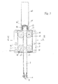
- the suspension 5 has a retaining member 6, which is guided in a housing 7 and is secured by a stop 14 against falling down. At the stop 14 opposite end of the holding member 6, a terminal 8 is provided for the determination of the contact wire 9.
- the holding member 6 is guided within the housing 7 between rollers 11, which are fastened by means of axles 10 on the housing 7.
- the rollers 11 have on their outer sheath grooves 18, the profile of the outer profile of the holding member 6 in the region of the rollers is gegentechnisch same.
- the holding member 6 is led out through the cover 12 of the housing 7, wherein at the top of the holding member is looped by a spring 13 which is supported on the one hand on the cover 12 and on the other hand on the stop 14.
- the stop 14 in turn is only briefly on the stop tube 15, which surrounds the spring 13 outside when swinging after a bracket passage thereby lifted holding member down.
- the housing 7 is secured to the support tube 3 by means not shown bracket, which are guided through fastening holes 16 and 17 in the rear wall of the housing and bolted from the front.
- the fastening holes 16 are designed as elongated holes to allow an angular adjustment of the housing 7 with respect to the direction of the support tube 3.
- rollers 11 are mounted on the axles 12 via bearings 19 in order to allow a very low-friction adjustment of the holding member 6 with respect to the housing 7.
- the stop tube 15 and the stopper 14 outside surrounded protective tube 20 is provided to prevent the ingress of dirt or water in the device according to the invention.
- the protective tube 20 is lockable in a manner not shown at its free end by means of a lid.
- the entire suspension 5 is arranged on the support tube 3 so that the pressure of the pantograph bracket takes place in the axial longitudinal direction of the support tube 6. This is in addition to the adjustability of the holes formed as slots 16 also still the Length of the tether 3 'set so that the support tube 3 is approximately parallel to the plane of the track. This means that, for example, in inclined track curves of a curve, the setting of the support tube 3 is different than in a straight track, in which the support arm 3 is set substantially horizontally.
- the grinding of the contact wire 9 is always exactly the same area, since it can not come to a lateral pivoting or rotation of the contact wire, as for example in the prior art FIG. 1 could occur depending on the pivotal position of the clamping arm 4 and subsequently the support tube 13.
Landscapes
- Engineering & Computer Science (AREA)
- Mechanical Engineering (AREA)
- Current-Collector Devices For Electrically Propelled Vehicles (AREA)
- Suspension Of Electric Lines Or Cables (AREA)
Abstract
Description
- Die Erfindung bezieht sich auf eine Aufhängung für den Oberleitungsfahrdraht elektrisch betriebener Fahrzeuge, insbesondere schienengebundener Fahrzeuge, bei welcher eine den Fahrdraht haltende Klemme an einem vertikal bewegbaren Halteorgan vorgesehen ist.
- Bei einer derartigen Ausbildung, wie sie z.B. aus der
DE 519 552 C1 hervorgeht, ist die den Fahrdraht haltende Klemme an teleskopartig ineinander schiebbaren Teilen befestigt, wobei die teleskopartig ineinander schiebbaren Teile durch eine zentral vorgesehene Druckfeder im Sinne eines Ausfahrens der Teile vorbelastet sind. Diese bekannte Ausbildung hat den Nachteil, dass durch diese teleskopartig ineinander schiebbaren Teile eine exakte Führung in vertikaler Richtung nicht gegeben ist, wobei zudem Eckzugkräfte bzw. Schrägzugkräfte von dieser Halterung nicht aufgenommen werden können, da es durch schräg eingebrachte Kräfte zu einem Verkanten der teleskopartig ineinander schiebbaren Teile kommen kann, was dazu führt, dass ein Zusammenschieben nicht mehr möglich ist und die gesamte Aufhängung eine starre Aufhängung bildet. - Der Erfindung liegt nun die Aufgabe zu Grunde eine Aufhängung für den Oberleitungsfahrdraht zu schaffen, mit welcher eine exakte Vertikalführung der Klemme erzielt wird, und zwar auch in jenen Bereichen, in welchen auf die Oberleitung nicht bloß das Eigengewicht wirkt, sondern auch Schräg- oder Eckzugkräfte aufzunehmen sind.
- Erfindungsgemäß wird diese Aufgabe dadurch gelöst, dass das vertikal bewegbare Halteorgan stabförmig ausbildet und in einem Gehäuse in axialer Richtung geführt ist, wobei das Halteorgan an seinem der Klemme abgewandten Ende mit einen Herausfallen verhindernden Anschlag versehen ist. Eine derartige Aufhängung hält den Fahrdraht lagerichtig in der gewünschten Stellung zum Stromabnehmer und hat zudem dynamisch günstigere Eigenschaften als die herkömmlichen Systeme. Herkömmliche Fahrdrahthalter übernehmen durch ihre Ausbildung die Schrägstellung, die zu haltenden Eckzüge auch anteilige Lasten. Durch die definierte Lastaufnahme der Klemme kann auf Stützpunkthänger verzichtet werden, wobei zusätzlich auch der Einbau eines Y-Seiles entfallen kann.
- Vorteilhafterweise kann zur Führung des Halteorgans an je einer horizontalen Achse gelagerte Rollen am Gehäuse vorgesehen sein. Damit wird ein reibungsarmes lagerichtiges Führen des Halteorgans erzielt. Damit von den Rollen nicht nur radial wirkende Kräfte sondern auch in Achsrichtung der Rollen eingeleitete Kräfte aufgenommen werden können, können die Rollen am Außenmantel mit je einer umlaufenden Rille versehen sein, wobei die Rille im Eingriffsbereich mit dem stabförmigen Halteorgan vorzugsweise ein dem Profil des stabförmigen Halteorgans entsprechendes Gegenprofil aufweisen. Damit quer zur Gleislängsachse verlaufende Kräfte besonders sicher aufgenommen werden können, können die Achsen der Rollen parallel zur Längsachse des zugehörigen Gleises verlaufen. Damit werden die Hauptkräfte die dann quer zur Längsrichtung des Gleises verlaufen, in die Rollen radial eingebracht, womit ein Klemmen oder Herausspringen der Halteorgane aus den Rollen verhindert ist.
- Der Anschlag kann dabei über eine Druckfeder am Deckel des Gehäuses abgestützt sein, wodurch die gesamte Last am Stützpunkt sowie zumindest die halbe Last des Fahrdrahtes bis zu den angrenzenden Feldhängern durch die definierte Federkraft in der Aufhängung übernommen wird. Es wird damit das Anheben des Fahrdrahtes beim Vorbeifahren des Stromabnehmers im ersten Schritt erleichtert, wobei durch das Aufhören der Federkraft am Ende der Bewegung das gesamte Gewicht der Oberleitung auf dem Stromabnehmer aufliegt. Diese Auflagekraft nimmt aufgrund der Federcharakteristik bis zum Ende der Aufwärtsbewegung des mit der Klemme versehenen Halteorgans zu und ergibt somit eine dynamische Auflagekraft der Oberleitung an dem Stromabnehmer.
- Für eine besonders sichere Führung des Halteorgans und der Feder kann vom Deckel des Gehäuses ein nach außen gerichtetes koaxiales Anschlagrohr für das Halteorgan ausgehen, wobei in dem Anschlagrohr die Feder geführt ist, welche das Halteorgan außen umschlingt. Damit steht das Innere des Gehäuses zur Gänze zur Führung mittels der besagten Rollen zur Verfügung. Außerdem ist durch die Anordnung des Anschlagrohres verhindert, dass innerhalb des Gehäuses, in dem sich die Rollen befinden, auch noch die Führung für die Feder und Anschlag vorgesehen werden muss.
- Das Gehäuse kann an einem Tragrohr eines herkömmlichen Auslegersystems befestigt sein, womit erreicht wird, dass herkömmliche Aufhängungen auf einfache Weise umgerüstet werden können. Dabei kann das Tragrohr parallel zur Neigung der Ebene des Gleises verlaufen, was den Vorteil hat, dass die Druckkräfte vom Stromabnehmer in axialer Richtung des Halteorgans eingebracht werden. Um diese Ausrichtung des Gehäuses im Bezug auf den Tragarm besonders genau einstellen zu können, weist das Gehäuse Langlöcher zur Aufnahme der Befestigungsmittel zum Verbinden mit dem Tragrohr auf. Damit ist eine Feinjustierung zusätzlich zu der Ausrichtung des Tragrohres ermöglicht.
- Zusammenfassend kann festgehalten werden, dass die Klemme durch die vertikale Führung des Fahrdraht bei Durchfahrt des Stromabnehmers den Fahrdraht lagerichtigen in Position hält, wogegen bei herkömmlichen Fahrdrahtseitenhaltern die nach Anhubkraft des Stromabnehmers der Fahrdraht in der Lage zum Stromabnehmer ausgedreht wird, was zu einer schrägen Beschleifung des Fahrdrahtes führen kann. Weitere Vorteile sind:
- Durch die vertikale Führung des Fahrdrahtes ergibt sich auch eine definierte Anhubfreiheit am Stützpunkt. Diese wird auch durch einen Anschlag gewährleistet. Bei herkömmlichen Systemen kann hingegen diese Anhubfreiheit aufgrund der Parameter (wie z.B: Eckzug) variieren.
- Durch die Konstruktion der Klemme am Auslenkungspunkt sind keine weiteren Bauteile für die seitliche Festlegung notwendig. Damit ergeben sich weiters keine Probleme bezüglich Bügelfreiheit von den Bauteilen der seitlichen Festlegung - speziell in Weichenbereichen; und keine Probleme mit Bauteilen von Nachbargleisen, welche eine andere Schaltgruppe aufweisen (wie z.B. zwei- oder mehrgleisige Strecken) - Arbeitssicherheit bei Bau und Erhaltung.
- Die Übernahme der Last durch die Klemme ergibt auch den Vorteil, dass auf Mindesteckzüge des Fahrdrahtes in der Planung verzichtet werden kann. Dieser Mindesteckzug ergibt sich bei den herkömmlichen Ausbildungen aus der Notwendigkeit, dass die Seitenhalter zumindest kleine Teile der Stützpunktbelastungen übernehmen müssen, um keine "harten Punkte" zu bilden.
- In der Zeichnung ist ein Ausführungsbeispiel des Erfindungsgegenstandes dargestellt.
-
Figur 1 zeigt eine herkömmliche Ausführung der Aufhängung des Oberleitungsdrahts für schienengebundene Fahrzeuge. -
Figur 2 gibt in analoger Darstellung die erfindungsgemäß abgewandelte Ausführung der Aufhängung wieder. -
Figur 3 veranschaulicht in größerem Maßstab die Fahrdrahtaufhängung als solche wobeiFigur 3 einen Schnitt nach Linie III-III derFigur 4 ist. -
Figur 4 ihrerseits ist ein Schnitt nach Linie IV-IV derFigur 3 in noch größerem Maßstab. - Bei einer herkömmlichen Abspannung 1 wird ein Auskragarm 2 durch einen Haltearm 2' über Isolatoren an einem tragenden Objekt, also einer Mauer oder einem Mast gehalten. Von dem Auskragarm 2 geht ein Tragrohr 3 in etwa horizontaler Richtung aus, welches mittels eines Seiles 3' in dieser Lage gehalten ist. Bei einer Ausführung gemäß dem Stand der Technik wie sie in
Figur 1 dargestellt ist, geht vom Ende des Tragrohres ein Spannarm 4 aus, welcher gelenkig mit dem Tragrohr 3 verbunden ist. Das Tragrohr 3 seinerseits ist gelenkig mit dem Auskragarm 2 verbunden, sodass unterschiedliche Längsbewegungen des Gehäuses 7 zum Auskragarm 2 ausgeglichen werden können. Das Tragrohr 3 reicht dabei bis nahezu über die gesamte Gleisbreite, wobei sich der Spannarm 4 dann vom Ende des Tragrohrs 1 bis in die Mitte des Gleises erstreckt. - Bei der erfindungsgemäßen Ausbildung gemäß
Figur 2 ist an dem Tragrohr 3 an Stelle des Spannarmes 4 eine Aufhängung 5 befestigt, wobei diese Aufhängung ebenfalls über ein Halteseil 3' gegen Absenken gehalten ist. Das Tragrohr 3 reicht dabei lediglich bis knapp über die Mitte des Gleises. - Die erfindungsgemäße Aufhängung 5 weißt ein Halteorgan 6 auf, das in einem Gehäuse 7 geführt ist und mittels eines Anschlages 14 gegen dem Herausfallen nach unten gesichert ist. An dem Anschlag 14 gegenüberliegenden Ende des Halteorgans 6 ist eine Klemme 8 für die Festlegung des Fahrdrahtes 9 vorgesehen.
- Das Halteorgan 6 ist innerhalb des Gehäuses 7 zwischen Rollen 11 geführt, die über Achsen 10 am Gehäuse 7 befestigt sind.
- Die Rollen 11 weisen auf ihrem Außenmantel Rillen 18 auf, deren Profil dem Außenprofil des Halteorgans 6 im Bereich der Rollen gegengleich ist.
- Das Halteorgan 6 ist durch den Deckel 12 des Gehäuses 7 herausgeführt, wobei an dem oberen Bereich das Halteorgan durch eine Feder 13 umschlungen ist, die sich einerseits am Deckel 12 und andererseits am Anschlag 14 abstützt. Der Anschlag 14 seinerseits liegt nur dann kurzzeitig am Anschlagrohr 15 auf, welches die Feder 13 außen umgibt, wenn nach einer Bügeldurchfahrt das dadurch angehobene Halteorgan nach unten schwingt.
- Das Gehäuse 7 ist am Tragrohr 3 mittels nicht dargestellter Bügel befestigt, welche durch Befestigungslöcher 16 und 17 in der Gehäuserückwand hindurch geführt und von der Vorderseite her verschraubt sind. An einer Seite des Gehäuses sind die Befestigungslöcher 16 als Langlöcher ausgeführt um eine winkelmäßige Einstellung des Gehäuses 7 in Bezug auf die Richtung des Tragrohres 3 zu ermöglichen.
- Wie aus
Figur 4 ersichtlich, sind die Rollen 11 an den Achsen 12 über Lager 19 gelagert, um eine möglichst reibungsarme Verstellmöglichkeit des Halteorgans 6 in Bezug auf das Gehäuse 7 zu ermöglichen. - Am Deckel 12 des Gehäuses 7 ist noch ein, das Anschlagrohr 15 und den Anschlag 14 außen umgebenes Schutzrohr 20 vorgesehen, um das Eindringen von Schmutz oder Wasser in die erfindungsgemäße Vorrichtung zu verhindern.
- In nicht dargestellter Weise kann an der den Anschlag 14 befestigenden Schraube 14' die Möglichkeit der Befestigung einer elektrischen Verbindung zum Stromausgleich angebracht werden.
- Das Schutzrohr 20 ist in nicht dargestellter Weise an seinem freien Ende mittels eines Deckels abschließbar.
- Die gesamte Aufhängung 5 ist dabei am Tragrohr 3 so angeordnet, dass der Druck des Stromabnehmerbügels in Achslängsrichtung dessen Tragrohres 6 erfolgt. Dazu ist neben der Einstellbarkeit über die als Langlöcher ausgebildeten Befestigungslöcher 16 auch noch die Länge des Halteseils 3' so eingestellt, dass das Tragrohr 3 annähernd parallel zur Ebene des Gleises verläuft. Dies bedeutet, dass beispielsweise in geneigten Gleisverläufen einer Kurve die Einstellung des Tragrohres 3 anders ist als in einer geraden Gleisführung, bei welcher der Tragarm 3 im Wesentlichen horizontal eingestellt ist.
- Bei in Betrieb befindlicher Vorrichtung befindet sich das Tragrohr 6 gegenüber dem Gehäuse 7 in der in
Figur 3 wiedergegebenen Lage, bei welcher die Feder 13 zusammengedrückt ist und der Anschlag 14 nahezu am Anschlagrohr 15 aufliegt. Sobald der Fahrdraht 9 durch den darüber schleifenden Stromabnehmerbügel des Schienenfahrzeuges angehoben wird, erfolgt ein Verstellen des Halteorgans 6 in Achsrichtung, wobei die erste Anhebebewegung durch die Feder 13 unterstützt wird und damit ein leichtes Ausweichen des Halteorgans 6 in Bezug auf das Gehäuse 7 ermöglicht ist. Die Kraft der Feder 13 nimmt in Abhängigkeit von dem Ausmaß der Verstellung des Halteorgans 6 ab je weiter das Halteorgan 6 in das Gehäuse 7 eingeschoben wird. Sobald der Federweg der Feder 13 ausgeschöpft ist, liegt das gesamte Gewicht des Fahrdrahtes am Stromabnehmerbügel des Schienenfahrzeuges auf, womit ein sicheres Anliegen des Fahrdrahtes auf der Palette des Stromabnehmerbügels gewährleistet ist. - Außerdem erfolgt das Beschleifen des Fahrdrahtes 9 immer exakt am gleichen Bereich, da es zu einem seitlichen Verschwenken bzw. Verdrehen des Fahrdrahtes nicht kommen kann, wie es beispielsweise beim Stand der Technik gemäß
Figur 1 in Anhängigkeit von der Schwenklage des Spannarmes 4 und in weiterer Folge des Tragrohres 13 auftreten könnte. - Quer zum Längsverlauf des Fahrdrahtes 9 auftretende Kräfte werden bei der erfindungsgemäßen Ausbildung durch die Lagerung 19 der Rollen 11 aufgefangen, wobei die in die Lagerung eingebrachten Kräfte radial auf die Rollen einwirken und damit zur Gänze von der Lagerung und der Achsen 10, der Rollen aufgenommen werden können. Allfällige in Richtung der Achsen 10, der Rollen 11 auftretende Kräfte werden dadurch kompensiert, dass die Ausnehmungen 18 der Rollen 11 kongruent mit den Außenprofil des Halteorgans 6 übereinstimmen, womit eine Führung des Halteorgans 6 auch dann zuverlässig möglich ist, wenn Kräfte in Längsrichtung des Fahrdrahtes 9 auftreten.
- An der Unterseite des Gehäuses sind für den Arbeitnehmerschutz und gegen Verschmutzungen Abdeckungen 21 vorgesehen.
Claims (9)
- Aufhängung für den Oberleitungs-Fahrdraht elektrisch betriebener Fahrzeuge, insbesondere schienengebundener Fahrzeuge, bei welcher eine den Fahrdraht haltende Klemme an einem vertikal bewegbaren Halteorgan vorgesehen ist, dadurch gekennzeichnet, dass das vertikal bewegbare Halteorgan (6) stabförmig ausgebildet und in einem Gehäuse (7) in axialer Richtung geführt ist, wobei das Halteorgan (6) an seinem der Klemme (8) abgewandten Ende mit einem, ein Herausfallen verhindernden Anschlag (14) versehen ist.
- Aufhängung nach Anspruch 1, dadurch gekennzeichnet, dass zur Führung des Halteorgans (6) an je einer horizontalen Achse (10) gelagerte Rollen (11) am Gehäuse (7) vorgesehen sind.
- Aufhängung nach Anspruch 2, dadurch gekennzeichnet, dass die Rollen (11) am Außenmantel mit je einer umlaufenden Rille (18) versehen sind, wobei die Rille (18) im Eingriffsbereich mit dem stabförmigen Halteorgan (6) vorzugsweise ein dem Profil des stabförmigen Halteorgans (6) entsprechendes Gegenprofil aufweist.
- Aufhängung nach Anspruch 2 oder 3, dadurch gekennzeichnet, dass die Achsen (10) der Rollen (11) parallel zur Längsachse des zugehörigen Gleises verläuft.
- Aufhängung nach einem der Ansprüche 1 bis 4, dadurch gekennzeichnet, dass der Anschlag (14) über eine Druckfeder (13) am Deckel des Gehäuses (12) abgestützt ist.
- Aufhängung nach Anspruch 5, dadurch gekennzeichnet, dass vom Deckel (12) des Gehäuses ein nach außen gerichtetes koaxiales Anschlagrohr (15) für das Halteorgan (6) ausgeht, wobei in dem Anschlagrohr (15) die Feder (13) geführt ist, welche das Halteorgan (6) außen umschlingt.
- Aufhängung nach einem der Ansprüche 1 bis 6, dadurch gekennzeichnet, dass das Gehäuse (7) an einem Tragrohr (3) eines herkömmlichen Auslegersystems (1) befestigt ist.
- Aufhängung nach Anspruch 5, dadurch gekennzeichnet, dass das Tragrohr (3) parallel zur Neigung der Ebene des Gleises verläuft.
- Aufhängung nach Anspruch 5 oder 6, dadurch gekennzeichnet, dass das Gehäuse (7) Langlöcher (16) zur Aufnahme der Befestigungsmittel zum Verbinden mit dem Tragrohr (3) aufweist.
Applications Claiming Priority (1)
| Application Number | Priority Date | Filing Date | Title |
|---|---|---|---|
| AT10462011A AT511767B1 (de) | 2011-07-15 | 2011-07-15 | Aufhängung für den oberleitungsfahrdraht elektrisch betriebener fahrzeuge |
Publications (3)
| Publication Number | Publication Date |
|---|---|
| EP2546095A2 true EP2546095A2 (de) | 2013-01-16 |
| EP2546095A3 EP2546095A3 (de) | 2014-03-05 |
| EP2546095B1 EP2546095B1 (de) | 2016-06-15 |
Family
ID=46458276
Family Applications (1)
| Application Number | Title | Priority Date | Filing Date |
|---|---|---|---|
| EP12174779.4A Active EP2546095B1 (de) | 2011-07-15 | 2012-07-03 | Dynamische Fahrdrahtklemme |
Country Status (2)
| Country | Link |
|---|---|
| EP (1) | EP2546095B1 (de) |
| AT (1) | AT511767B1 (de) |
Cited By (2)
| Publication number | Priority date | Publication date | Assignee | Title |
|---|---|---|---|---|
| CN110789404A (zh) * | 2019-10-30 | 2020-02-14 | 徐州中能电力科技有限公司 | 一种电气化铁路接触网的支撑机构 |
| CN112677830A (zh) * | 2021-01-24 | 2021-04-20 | 于海文 | 主动驱动式收放支持装置、移动接触网及操作方法 |
Families Citing this family (1)
| Publication number | Priority date | Publication date | Assignee | Title |
|---|---|---|---|---|
| DE102023209294A1 (de) * | 2023-09-22 | 2025-03-27 | Siemens Mobility GmbH | Verbindungsvorrichtung einer Oberleitungsanlage und Oberleitungsanlage |
Citations (1)
| Publication number | Priority date | Publication date | Assignee | Title |
|---|---|---|---|---|
| DE519552C (de) | 1931-03-02 | Nelken & Co G M B H | Fahrdrahtaufhaengung fuer elektrische Bahnen |
Family Cites Families (6)
| Publication number | Priority date | Publication date | Assignee | Title |
|---|---|---|---|---|
| GB811230A (en) * | 1955-07-04 | 1959-04-02 | Kummler & Matter Ag | Improvements in conductor wire systems for electric railways |
| GB821264A (en) * | 1956-12-05 | 1959-10-07 | British Insulated Callenders | Improvements in or relating to overhead electrification systems for railways |
| GB8333744D0 (en) * | 1983-12-19 | 1984-01-25 | Bicc Plc | Overhead electric traction system |
| NO169333C (no) * | 1989-12-20 | 1992-06-10 | Alupro N As | Anordning for opphengning av kjoereledning for skinnegaaende kjoeretoeyer. |
| JP3398037B2 (ja) * | 1998-01-09 | 2003-04-21 | 東日本旅客鉄道株式会社 | カテナリ式剛体電車線 |
| CN101698391B (zh) * | 2009-10-30 | 2012-09-26 | 汉和飞轮(北京)电气化器材有限公司 | 电气化铁路接触网的正定位整体式腕臂 |
-
2011
- 2011-07-15 AT AT10462011A patent/AT511767B1/de active
-
2012
- 2012-07-03 EP EP12174779.4A patent/EP2546095B1/de active Active
Patent Citations (1)
| Publication number | Priority date | Publication date | Assignee | Title |
|---|---|---|---|---|
| DE519552C (de) | 1931-03-02 | Nelken & Co G M B H | Fahrdrahtaufhaengung fuer elektrische Bahnen |
Cited By (2)
| Publication number | Priority date | Publication date | Assignee | Title |
|---|---|---|---|---|
| CN110789404A (zh) * | 2019-10-30 | 2020-02-14 | 徐州中能电力科技有限公司 | 一种电气化铁路接触网的支撑机构 |
| CN112677830A (zh) * | 2021-01-24 | 2021-04-20 | 于海文 | 主动驱动式收放支持装置、移动接触网及操作方法 |
Also Published As
| Publication number | Publication date |
|---|---|
| EP2546095B1 (de) | 2016-06-15 |
| AT511767B1 (de) | 2013-07-15 |
| AT511767A1 (de) | 2013-02-15 |
| EP2546095A3 (de) | 2014-03-05 |
Similar Documents
| Publication | Publication Date | Title |
|---|---|---|
| EP2363314B1 (de) | Vorrichtung zur Kopplung von elastischen und starren Fahrleitungssystemen | |
| EP3406501B1 (de) | Fahrzeug mit mindestens einer kanalvorrichtung und verfahren zum ausrüsten eines fahrzeugs mit einer kanalvorrichtung | |
| EP2546095B1 (de) | Dynamische Fahrdrahtklemme | |
| AT515083B1 (de) | Fahrleitungsmast für Oberleitungsanlagen elektrischer Schienenfahrzeuge | |
| DE102012003579B3 (de) | Nachspanneinrichtung für Kettenfahrleitungen elektrischer Bahnen | |
| DE102012101620A1 (de) | Isolationsträger für eine Stromschiene für elektrisch getriebene Schienenfahrzeuge | |
| EP2947037B1 (de) | Kran | |
| DE102009033447A1 (de) | Oberleitungsanlage | |
| DE102007058729A1 (de) | Walzvorrichtung mit Verstellvorrichtung | |
| EP3737582B1 (de) | Klemme und fahrdrahtträgeranordnung | |
| DE102006012766A1 (de) | Befestigungssystem für medizintechnische Geräte | |
| EP3681836B1 (de) | Installationseinrichtung für eine verwendung in einem aufzugschacht | |
| EP2960103A1 (de) | Fahrleitungsmast für oberleitungsanlagen elektrischer schienenfahrzeuge | |
| DE102011017237A1 (de) | Haltevorrichtung für eine Leitung eines Kraftwagens | |
| AT515966B1 (de) | Fahrleitungsmast für Oberleitungsanlagen elektrischer Schienenfahrzeuge | |
| AT516864B1 (de) | Fahrleitungsmast für Oberleitungsanlagen elektrischer Schienenfahrzeuge | |
| EP2620316B1 (de) | Halter für den Fahrdraht von Einfach-Fahrleitungen | |
| EP2469162B1 (de) | Haltevorrichtung für eine Leuchte | |
| EP4054967B1 (de) | Installationseinrichtung für eine verwendung in einem aufzugschacht | |
| AT516347B1 (de) | Anordnung zur Aufhängung mindestens eines Fahrdrahtes elektrischer Bahnen | |
| DE202014101239U1 (de) | Sicherungseinrichtung für den Grabenverbau | |
| AT513276B1 (de) | Werkzeugmaschine mit einem Längsschlitten | |
| EP3157797B1 (de) | Verbindungselement zur drehbaren verbindung eines wagenkastens mit einem drehgestell eines schienenfahrzeugs | |
| EP1787853A1 (de) | Tragwerk für eine Fahrleitung | |
| DE1465081B1 (de) | Kastenfoermiges schutzgehaeuse fuer stromschienen insbesondere von portalkraenen auf einer kai-anlage |
Legal Events
| Date | Code | Title | Description |
|---|---|---|---|
| PUAI | Public reference made under article 153(3) epc to a published international application that has entered the european phase |
Free format text: ORIGINAL CODE: 0009012 |
|
| AK | Designated contracting states |
Kind code of ref document: A2 Designated state(s): AL AT BE BG CH CY CZ DE DK EE ES FI FR GB GR HR HU IE IS IT LI LT LU LV MC MK MT NL NO PL PT RO RS SE SI SK SM TR |
|
| AX | Request for extension of the european patent |
Extension state: BA ME |
|
| PUAL | Search report despatched |
Free format text: ORIGINAL CODE: 0009013 |
|
| AK | Designated contracting states |
Kind code of ref document: A3 Designated state(s): AL AT BE BG CH CY CZ DE DK EE ES FI FR GB GR HR HU IE IS IT LI LT LU LV MC MK MT NL NO PL PT RO RS SE SI SK SM TR |
|
| AX | Request for extension of the european patent |
Extension state: BA ME |
|
| RIC1 | Information provided on ipc code assigned before grant |
Ipc: B60M 1/23 20060101AFI20140129BHEP |
|
| 17P | Request for examination filed |
Effective date: 20140905 |
|
| RAX | Requested extension states of the european patent have changed |
Extension state: ME Payment date: 20140905 Extension state: BA Payment date: 20140905 |
|
| RBV | Designated contracting states (corrected) |
Designated state(s): AL AT BE BG CH CY CZ DE DK EE ES FI FR GB GR HR HU IE IS IT LI LT LU LV MC MK MT NL NO PL PT RO RS SE SI SK SM TR |
|
| GRAP | Despatch of communication of intention to grant a patent |
Free format text: ORIGINAL CODE: EPIDOSNIGR1 |
|
| INTG | Intention to grant announced |
Effective date: 20160205 |
|
| GRAS | Grant fee paid |
Free format text: ORIGINAL CODE: EPIDOSNIGR3 |
|
| GRAA | (expected) grant |
Free format text: ORIGINAL CODE: 0009210 |
|
| AK | Designated contracting states |
Kind code of ref document: B1 Designated state(s): AL AT BE BG CH CY CZ DE DK EE ES FI FR GB GR HR HU IE IS IT LI LT LU LV MC MK MT NL NO PL PT RO RS SE SI SK SM TR |
|
| AX | Request for extension of the european patent |
Extension state: BA ME |
|
| REG | Reference to a national code |
Ref country code: CH Ref legal event code: EP Ref country code: GB Ref legal event code: FG4D Free format text: NOT ENGLISH |
|
| REG | Reference to a national code |
Ref country code: IE Ref legal event code: FG4D Free format text: LANGUAGE OF EP DOCUMENT: GERMAN |
|
| REG | Reference to a national code |
Ref country code: AT Ref legal event code: REF Ref document number: 806326 Country of ref document: AT Kind code of ref document: T Effective date: 20160715 |
|
| REG | Reference to a national code |
Ref country code: DE Ref legal event code: R096 Ref document number: 502012007401 Country of ref document: DE |
|
| REG | Reference to a national code |
Ref country code: LT Ref legal event code: MG4D |
|
| REG | Reference to a national code |
Ref country code: NL Ref legal event code: MP Effective date: 20160615 |
|
| PG25 | Lapsed in a contracting state [announced via postgrant information from national office to epo] |
Ref country code: NO Free format text: LAPSE BECAUSE OF FAILURE TO SUBMIT A TRANSLATION OF THE DESCRIPTION OR TO PAY THE FEE WITHIN THE PRESCRIBED TIME-LIMIT Effective date: 20160915 Ref country code: FI Free format text: LAPSE BECAUSE OF FAILURE TO SUBMIT A TRANSLATION OF THE DESCRIPTION OR TO PAY THE FEE WITHIN THE PRESCRIBED TIME-LIMIT Effective date: 20160615 Ref country code: LT Free format text: LAPSE BECAUSE OF FAILURE TO SUBMIT A TRANSLATION OF THE DESCRIPTION OR TO PAY THE FEE WITHIN THE PRESCRIBED TIME-LIMIT Effective date: 20160615 |
|
| PG25 | Lapsed in a contracting state [announced via postgrant information from national office to epo] |
Ref country code: NL Free format text: LAPSE BECAUSE OF FAILURE TO SUBMIT A TRANSLATION OF THE DESCRIPTION OR TO PAY THE FEE WITHIN THE PRESCRIBED TIME-LIMIT Effective date: 20160615 Ref country code: GR Free format text: LAPSE BECAUSE OF FAILURE TO SUBMIT A TRANSLATION OF THE DESCRIPTION OR TO PAY THE FEE WITHIN THE PRESCRIBED TIME-LIMIT Effective date: 20160916 Ref country code: RS Free format text: LAPSE BECAUSE OF FAILURE TO SUBMIT A TRANSLATION OF THE DESCRIPTION OR TO PAY THE FEE WITHIN THE PRESCRIBED TIME-LIMIT Effective date: 20160615 Ref country code: SE Free format text: LAPSE BECAUSE OF FAILURE TO SUBMIT A TRANSLATION OF THE DESCRIPTION OR TO PAY THE FEE WITHIN THE PRESCRIBED TIME-LIMIT Effective date: 20160615 Ref country code: LV Free format text: LAPSE BECAUSE OF FAILURE TO SUBMIT A TRANSLATION OF THE DESCRIPTION OR TO PAY THE FEE WITHIN THE PRESCRIBED TIME-LIMIT Effective date: 20160615 |
|
| PG25 | Lapsed in a contracting state [announced via postgrant information from national office to epo] |
Ref country code: BE Free format text: LAPSE BECAUSE OF NON-PAYMENT OF DUE FEES Effective date: 20160731 |
|
| PG25 | Lapsed in a contracting state [announced via postgrant information from national office to epo] |
Ref country code: IS Free format text: LAPSE BECAUSE OF FAILURE TO SUBMIT A TRANSLATION OF THE DESCRIPTION OR TO PAY THE FEE WITHIN THE PRESCRIBED TIME-LIMIT Effective date: 20161015 Ref country code: CZ Free format text: LAPSE BECAUSE OF FAILURE TO SUBMIT A TRANSLATION OF THE DESCRIPTION OR TO PAY THE FEE WITHIN THE PRESCRIBED TIME-LIMIT Effective date: 20160615 Ref country code: SK Free format text: LAPSE BECAUSE OF FAILURE TO SUBMIT A TRANSLATION OF THE DESCRIPTION OR TO PAY THE FEE WITHIN THE PRESCRIBED TIME-LIMIT Effective date: 20160615 Ref country code: EE Free format text: LAPSE BECAUSE OF FAILURE TO SUBMIT A TRANSLATION OF THE DESCRIPTION OR TO PAY THE FEE WITHIN THE PRESCRIBED TIME-LIMIT Effective date: 20160615 Ref country code: RO Free format text: LAPSE BECAUSE OF FAILURE TO SUBMIT A TRANSLATION OF THE DESCRIPTION OR TO PAY THE FEE WITHIN THE PRESCRIBED TIME-LIMIT Effective date: 20160615 Ref country code: IT Free format text: LAPSE BECAUSE OF FAILURE TO SUBMIT A TRANSLATION OF THE DESCRIPTION OR TO PAY THE FEE WITHIN THE PRESCRIBED TIME-LIMIT Effective date: 20160615 |
|
| REG | Reference to a national code |
Ref country code: DE Ref legal event code: R119 Ref document number: 502012007401 Country of ref document: DE |
|
| PG25 | Lapsed in a contracting state [announced via postgrant information from national office to epo] |
Ref country code: SM Free format text: LAPSE BECAUSE OF FAILURE TO SUBMIT A TRANSLATION OF THE DESCRIPTION OR TO PAY THE FEE WITHIN THE PRESCRIBED TIME-LIMIT Effective date: 20160615 Ref country code: PL Free format text: LAPSE BECAUSE OF FAILURE TO SUBMIT A TRANSLATION OF THE DESCRIPTION OR TO PAY THE FEE WITHIN THE PRESCRIBED TIME-LIMIT Effective date: 20160615 Ref country code: PT Free format text: LAPSE BECAUSE OF FAILURE TO SUBMIT A TRANSLATION OF THE DESCRIPTION OR TO PAY THE FEE WITHIN THE PRESCRIBED TIME-LIMIT Effective date: 20161017 Ref country code: ES Free format text: LAPSE BECAUSE OF FAILURE TO SUBMIT A TRANSLATION OF THE DESCRIPTION OR TO PAY THE FEE WITHIN THE PRESCRIBED TIME-LIMIT Effective date: 20160615 |
|
| REG | Reference to a national code |
Ref country code: CH Ref legal event code: PL |
|
| PG25 | Lapsed in a contracting state [announced via postgrant information from national office to epo] |
Ref country code: MC Free format text: LAPSE BECAUSE OF FAILURE TO SUBMIT A TRANSLATION OF THE DESCRIPTION OR TO PAY THE FEE WITHIN THE PRESCRIBED TIME-LIMIT Effective date: 20160615 |
|
| PLBE | No opposition filed within time limit |
Free format text: ORIGINAL CODE: 0009261 |
|
| STAA | Information on the status of an ep patent application or granted ep patent |
Free format text: STATUS: NO OPPOSITION FILED WITHIN TIME LIMIT |
|
| PG25 | Lapsed in a contracting state [announced via postgrant information from national office to epo] |
Ref country code: FR Free format text: LAPSE BECAUSE OF NON-PAYMENT OF DUE FEES Effective date: 20160816 Ref country code: CH Free format text: LAPSE BECAUSE OF NON-PAYMENT OF DUE FEES Effective date: 20160731 Ref country code: DE Free format text: LAPSE BECAUSE OF NON-PAYMENT OF DUE FEES Effective date: 20170201 Ref country code: LI Free format text: LAPSE BECAUSE OF NON-PAYMENT OF DUE FEES Effective date: 20160731 |
|
| REG | Reference to a national code |
Ref country code: FR Ref legal event code: ST Effective date: 20170331 |
|
| REG | Reference to a national code |
Ref country code: IE Ref legal event code: MM4A |
|
| 26N | No opposition filed |
Effective date: 20170316 |
|
| GBPC | Gb: european patent ceased through non-payment of renewal fee |
Effective date: 20160915 |
|
| PG25 | Lapsed in a contracting state [announced via postgrant information from national office to epo] |
Ref country code: DK Free format text: LAPSE BECAUSE OF FAILURE TO SUBMIT A TRANSLATION OF THE DESCRIPTION OR TO PAY THE FEE WITHIN THE PRESCRIBED TIME-LIMIT Effective date: 20160615 |
|
| PG25 | Lapsed in a contracting state [announced via postgrant information from national office to epo] |
Ref country code: IE Free format text: LAPSE BECAUSE OF NON-PAYMENT OF DUE FEES Effective date: 20160703 Ref country code: GB Free format text: LAPSE BECAUSE OF NON-PAYMENT OF DUE FEES Effective date: 20160915 |
|
| PG25 | Lapsed in a contracting state [announced via postgrant information from national office to epo] |
Ref country code: SI Free format text: LAPSE BECAUSE OF FAILURE TO SUBMIT A TRANSLATION OF THE DESCRIPTION OR TO PAY THE FEE WITHIN THE PRESCRIBED TIME-LIMIT Effective date: 20160615 Ref country code: LU Free format text: LAPSE BECAUSE OF NON-PAYMENT OF DUE FEES Effective date: 20160703 |
|
| PG25 | Lapsed in a contracting state [announced via postgrant information from national office to epo] |
Ref country code: CY Free format text: LAPSE BECAUSE OF FAILURE TO SUBMIT A TRANSLATION OF THE DESCRIPTION OR TO PAY THE FEE WITHIN THE PRESCRIBED TIME-LIMIT Effective date: 20160615 Ref country code: HU Free format text: LAPSE BECAUSE OF FAILURE TO SUBMIT A TRANSLATION OF THE DESCRIPTION OR TO PAY THE FEE WITHIN THE PRESCRIBED TIME-LIMIT; INVALID AB INITIO Effective date: 20120703 |
|
| PG25 | Lapsed in a contracting state [announced via postgrant information from national office to epo] |
Ref country code: HR Free format text: LAPSE BECAUSE OF FAILURE TO SUBMIT A TRANSLATION OF THE DESCRIPTION OR TO PAY THE FEE WITHIN THE PRESCRIBED TIME-LIMIT Effective date: 20160615 Ref country code: MK Free format text: LAPSE BECAUSE OF FAILURE TO SUBMIT A TRANSLATION OF THE DESCRIPTION OR TO PAY THE FEE WITHIN THE PRESCRIBED TIME-LIMIT Effective date: 20160615 Ref country code: TR Free format text: LAPSE BECAUSE OF FAILURE TO SUBMIT A TRANSLATION OF THE DESCRIPTION OR TO PAY THE FEE WITHIN THE PRESCRIBED TIME-LIMIT Effective date: 20160615 Ref country code: MT Free format text: LAPSE BECAUSE OF FAILURE TO SUBMIT A TRANSLATION OF THE DESCRIPTION OR TO PAY THE FEE WITHIN THE PRESCRIBED TIME-LIMIT Effective date: 20160615 |
|
| PG25 | Lapsed in a contracting state [announced via postgrant information from national office to epo] |
Ref country code: BG Free format text: LAPSE BECAUSE OF FAILURE TO SUBMIT A TRANSLATION OF THE DESCRIPTION OR TO PAY THE FEE WITHIN THE PRESCRIBED TIME-LIMIT Effective date: 20160615 |
|
| REG | Reference to a national code |
Ref country code: AT Ref legal event code: MM01 Ref document number: 806326 Country of ref document: AT Kind code of ref document: T Effective date: 20170703 |
|
| PG25 | Lapsed in a contracting state [announced via postgrant information from national office to epo] |
Ref country code: AL Free format text: LAPSE BECAUSE OF FAILURE TO SUBMIT A TRANSLATION OF THE DESCRIPTION OR TO PAY THE FEE WITHIN THE PRESCRIBED TIME-LIMIT Effective date: 20160615 |
|
| PG25 | Lapsed in a contracting state [announced via postgrant information from national office to epo] |
Ref country code: AT Free format text: LAPSE BECAUSE OF NON-PAYMENT OF DUE FEES Effective date: 20170703 |