EP2545202B1 - Kolbenring, und verfahren zur beschichtung eines kolbenrings - Google Patents
Kolbenring, und verfahren zur beschichtung eines kolbenrings Download PDFInfo
- Publication number
- EP2545202B1 EP2545202B1 EP11704223.4A EP11704223A EP2545202B1 EP 2545202 B1 EP2545202 B1 EP 2545202B1 EP 11704223 A EP11704223 A EP 11704223A EP 2545202 B1 EP2545202 B1 EP 2545202B1
- Authority
- EP
- European Patent Office
- Prior art keywords
- layer
- piston ring
- coating
- crn
- dlc
- Prior art date
- Legal status (The legal status is an assumption and is not a legal conclusion. Google has not performed a legal analysis and makes no representation as to the accuracy of the status listed.)
- Active
Links
- 238000000576 coating method Methods 0.000 title claims description 31
- 239000011248 coating agent Substances 0.000 title claims description 29
- 238000000034 method Methods 0.000 title claims description 10
- 239000010410 layer Substances 0.000 claims description 72
- 239000011651 chromium Substances 0.000 claims description 9
- 229910052751 metal Inorganic materials 0.000 claims description 7
- 239000002184 metal Substances 0.000 claims description 7
- 239000012790 adhesive layer Substances 0.000 claims description 6
- VYZAMTAEIAYCRO-UHFFFAOYSA-N Chromium Chemical compound [Cr] VYZAMTAEIAYCRO-UHFFFAOYSA-N 0.000 claims description 4
- 229910052804 chromium Inorganic materials 0.000 claims description 4
- 229910001018 Cast iron Inorganic materials 0.000 claims description 3
- 229910001208 Crucible steel Inorganic materials 0.000 claims description 3
- 239000010959 steel Substances 0.000 claims description 3
- 238000005229 chemical vapour deposition Methods 0.000 claims description 2
- 238000004544 sputter deposition Methods 0.000 claims description 2
- 239000000758 substrate Substances 0.000 claims description 2
- XEEYBQQBJWHFJM-UHFFFAOYSA-N Iron Chemical compound [Fe] XEEYBQQBJWHFJM-UHFFFAOYSA-N 0.000 description 6
- 230000006835 compression Effects 0.000 description 4
- 238000007906 compression Methods 0.000 description 4
- 229910052742 iron Inorganic materials 0.000 description 3
- 229910003481 amorphous carbon Inorganic materials 0.000 description 2
- 238000002485 combustion reaction Methods 0.000 description 2
- 238000010276 construction Methods 0.000 description 2
- 230000002950 deficient Effects 0.000 description 2
- 238000005461 lubrication Methods 0.000 description 2
- 239000000243 solution Substances 0.000 description 2
- OKTJSMMVPCPJKN-UHFFFAOYSA-N Carbon Chemical compound [C] OKTJSMMVPCPJKN-UHFFFAOYSA-N 0.000 description 1
- 229910001060 Gray iron Inorganic materials 0.000 description 1
- UFHFLCQGNIYNRP-UHFFFAOYSA-N Hydrogen Chemical compound [H][H] UFHFLCQGNIYNRP-UHFFFAOYSA-N 0.000 description 1
- 229910000676 Si alloy Inorganic materials 0.000 description 1
- XUIMIQQOPSSXEZ-UHFFFAOYSA-N Silicon Chemical compound [Si] XUIMIQQOPSSXEZ-UHFFFAOYSA-N 0.000 description 1
- RTAQQCXQSZGOHL-UHFFFAOYSA-N Titanium Chemical compound [Ti] RTAQQCXQSZGOHL-UHFFFAOYSA-N 0.000 description 1
- 239000000853 adhesive Substances 0.000 description 1
- 230000001070 adhesive effect Effects 0.000 description 1
- CSDREXVUYHZDNP-UHFFFAOYSA-N alumanylidynesilicon Chemical compound [Al].[Si] CSDREXVUYHZDNP-UHFFFAOYSA-N 0.000 description 1
- 229910052799 carbon Inorganic materials 0.000 description 1
- 230000000052 comparative effect Effects 0.000 description 1
- 238000011161 development Methods 0.000 description 1
- 230000018109 developmental process Effects 0.000 description 1
- 230000000694 effects Effects 0.000 description 1
- 230000001747 exhibiting effect Effects 0.000 description 1
- 238000002474 experimental method Methods 0.000 description 1
- 229910052739 hydrogen Inorganic materials 0.000 description 1
- 239000001257 hydrogen Substances 0.000 description 1
- 238000002347 injection Methods 0.000 description 1
- 239000007924 injection Substances 0.000 description 1
- 239000011229 interlayer Substances 0.000 description 1
- 239000000463 material Substances 0.000 description 1
- 239000003921 oil Substances 0.000 description 1
- 238000005240 physical vapour deposition Methods 0.000 description 1
- 239000010703 silicon Substances 0.000 description 1
- 229910052710 silicon Inorganic materials 0.000 description 1
- 239000000126 substance Substances 0.000 description 1
- 229910052719 titanium Inorganic materials 0.000 description 1
- 239000010936 titanium Substances 0.000 description 1
- 230000007704 transition Effects 0.000 description 1
- WFKWXMTUELFFGS-UHFFFAOYSA-N tungsten Chemical compound [W] WFKWXMTUELFFGS-UHFFFAOYSA-N 0.000 description 1
- 229910052721 tungsten Inorganic materials 0.000 description 1
- 239000010937 tungsten Substances 0.000 description 1
Images
Classifications
-
- C—CHEMISTRY; METALLURGY
- C23—COATING METALLIC MATERIAL; COATING MATERIAL WITH METALLIC MATERIAL; CHEMICAL SURFACE TREATMENT; DIFFUSION TREATMENT OF METALLIC MATERIAL; COATING BY VACUUM EVAPORATION, BY SPUTTERING, BY ION IMPLANTATION OR BY CHEMICAL VAPOUR DEPOSITION, IN GENERAL; INHIBITING CORROSION OF METALLIC MATERIAL OR INCRUSTATION IN GENERAL
- C23C—COATING METALLIC MATERIAL; COATING MATERIAL WITH METALLIC MATERIAL; SURFACE TREATMENT OF METALLIC MATERIAL BY DIFFUSION INTO THE SURFACE, BY CHEMICAL CONVERSION OR SUBSTITUTION; COATING BY VACUUM EVAPORATION, BY SPUTTERING, BY ION IMPLANTATION OR BY CHEMICAL VAPOUR DEPOSITION, IN GENERAL
- C23C28/00—Coating for obtaining at least two superposed coatings either by methods not provided for in a single one of groups C23C2/00 - C23C26/00 or by combinations of methods provided for in subclasses C23C and C25C or C25D
- C23C28/04—Coating for obtaining at least two superposed coatings either by methods not provided for in a single one of groups C23C2/00 - C23C26/00 or by combinations of methods provided for in subclasses C23C and C25C or C25D only coatings of inorganic non-metallic material
- C23C28/046—Coating for obtaining at least two superposed coatings either by methods not provided for in a single one of groups C23C2/00 - C23C26/00 or by combinations of methods provided for in subclasses C23C and C25C or C25D only coatings of inorganic non-metallic material with at least one amorphous inorganic material layer, e.g. DLC, a-C:H, a-C:Me, the layer being doped or not
-
- C—CHEMISTRY; METALLURGY
- C23—COATING METALLIC MATERIAL; COATING MATERIAL WITH METALLIC MATERIAL; CHEMICAL SURFACE TREATMENT; DIFFUSION TREATMENT OF METALLIC MATERIAL; COATING BY VACUUM EVAPORATION, BY SPUTTERING, BY ION IMPLANTATION OR BY CHEMICAL VAPOUR DEPOSITION, IN GENERAL; INHIBITING CORROSION OF METALLIC MATERIAL OR INCRUSTATION IN GENERAL
- C23C—COATING METALLIC MATERIAL; COATING MATERIAL WITH METALLIC MATERIAL; SURFACE TREATMENT OF METALLIC MATERIAL BY DIFFUSION INTO THE SURFACE, BY CHEMICAL CONVERSION OR SUBSTITUTION; COATING BY VACUUM EVAPORATION, BY SPUTTERING, BY ION IMPLANTATION OR BY CHEMICAL VAPOUR DEPOSITION, IN GENERAL
- C23C14/00—Coating by vacuum evaporation, by sputtering or by ion implantation of the coating forming material
- C23C14/06—Coating by vacuum evaporation, by sputtering or by ion implantation of the coating forming material characterised by the coating material
- C23C14/0605—Carbon
-
- C—CHEMISTRY; METALLURGY
- C23—COATING METALLIC MATERIAL; COATING MATERIAL WITH METALLIC MATERIAL; CHEMICAL SURFACE TREATMENT; DIFFUSION TREATMENT OF METALLIC MATERIAL; COATING BY VACUUM EVAPORATION, BY SPUTTERING, BY ION IMPLANTATION OR BY CHEMICAL VAPOUR DEPOSITION, IN GENERAL; INHIBITING CORROSION OF METALLIC MATERIAL OR INCRUSTATION IN GENERAL
- C23C—COATING METALLIC MATERIAL; COATING MATERIAL WITH METALLIC MATERIAL; SURFACE TREATMENT OF METALLIC MATERIAL BY DIFFUSION INTO THE SURFACE, BY CHEMICAL CONVERSION OR SUBSTITUTION; COATING BY VACUUM EVAPORATION, BY SPUTTERING, BY ION IMPLANTATION OR BY CHEMICAL VAPOUR DEPOSITION, IN GENERAL
- C23C14/00—Coating by vacuum evaporation, by sputtering or by ion implantation of the coating forming material
- C23C14/06—Coating by vacuum evaporation, by sputtering or by ion implantation of the coating forming material characterised by the coating material
- C23C14/0641—Nitrides
-
- C—CHEMISTRY; METALLURGY
- C23—COATING METALLIC MATERIAL; COATING MATERIAL WITH METALLIC MATERIAL; CHEMICAL SURFACE TREATMENT; DIFFUSION TREATMENT OF METALLIC MATERIAL; COATING BY VACUUM EVAPORATION, BY SPUTTERING, BY ION IMPLANTATION OR BY CHEMICAL VAPOUR DEPOSITION, IN GENERAL; INHIBITING CORROSION OF METALLIC MATERIAL OR INCRUSTATION IN GENERAL
- C23C—COATING METALLIC MATERIAL; COATING MATERIAL WITH METALLIC MATERIAL; SURFACE TREATMENT OF METALLIC MATERIAL BY DIFFUSION INTO THE SURFACE, BY CHEMICAL CONVERSION OR SUBSTITUTION; COATING BY VACUUM EVAPORATION, BY SPUTTERING, BY ION IMPLANTATION OR BY CHEMICAL VAPOUR DEPOSITION, IN GENERAL
- C23C16/00—Chemical coating by decomposition of gaseous compounds, without leaving reaction products of surface material in the coating, i.e. chemical vapour deposition [CVD] processes
- C23C16/22—Chemical coating by decomposition of gaseous compounds, without leaving reaction products of surface material in the coating, i.e. chemical vapour deposition [CVD] processes characterised by the deposition of inorganic material, other than metallic material
- C23C16/26—Deposition of carbon only
-
- C—CHEMISTRY; METALLURGY
- C23—COATING METALLIC MATERIAL; COATING MATERIAL WITH METALLIC MATERIAL; CHEMICAL SURFACE TREATMENT; DIFFUSION TREATMENT OF METALLIC MATERIAL; COATING BY VACUUM EVAPORATION, BY SPUTTERING, BY ION IMPLANTATION OR BY CHEMICAL VAPOUR DEPOSITION, IN GENERAL; INHIBITING CORROSION OF METALLIC MATERIAL OR INCRUSTATION IN GENERAL
- C23C—COATING METALLIC MATERIAL; COATING MATERIAL WITH METALLIC MATERIAL; SURFACE TREATMENT OF METALLIC MATERIAL BY DIFFUSION INTO THE SURFACE, BY CHEMICAL CONVERSION OR SUBSTITUTION; COATING BY VACUUM EVAPORATION, BY SPUTTERING, BY ION IMPLANTATION OR BY CHEMICAL VAPOUR DEPOSITION, IN GENERAL
- C23C28/00—Coating for obtaining at least two superposed coatings either by methods not provided for in a single one of groups C23C2/00 - C23C26/00 or by combinations of methods provided for in subclasses C23C and C25C or C25D
- C23C28/04—Coating for obtaining at least two superposed coatings either by methods not provided for in a single one of groups C23C2/00 - C23C26/00 or by combinations of methods provided for in subclasses C23C and C25C or C25D only coatings of inorganic non-metallic material
- C23C28/044—Coating for obtaining at least two superposed coatings either by methods not provided for in a single one of groups C23C2/00 - C23C26/00 or by combinations of methods provided for in subclasses C23C and C25C or C25D only coatings of inorganic non-metallic material coatings specially adapted for cutting tools or wear applications
-
- C—CHEMISTRY; METALLURGY
- C23—COATING METALLIC MATERIAL; COATING MATERIAL WITH METALLIC MATERIAL; CHEMICAL SURFACE TREATMENT; DIFFUSION TREATMENT OF METALLIC MATERIAL; COATING BY VACUUM EVAPORATION, BY SPUTTERING, BY ION IMPLANTATION OR BY CHEMICAL VAPOUR DEPOSITION, IN GENERAL; INHIBITING CORROSION OF METALLIC MATERIAL OR INCRUSTATION IN GENERAL
- C23C—COATING METALLIC MATERIAL; COATING MATERIAL WITH METALLIC MATERIAL; SURFACE TREATMENT OF METALLIC MATERIAL BY DIFFUSION INTO THE SURFACE, BY CHEMICAL CONVERSION OR SUBSTITUTION; COATING BY VACUUM EVAPORATION, BY SPUTTERING, BY ION IMPLANTATION OR BY CHEMICAL VAPOUR DEPOSITION, IN GENERAL
- C23C28/00—Coating for obtaining at least two superposed coatings either by methods not provided for in a single one of groups C23C2/00 - C23C26/00 or by combinations of methods provided for in subclasses C23C and C25C or C25D
- C23C28/40—Coatings including alternating layers following a pattern, a periodic or defined repetition
- C23C28/42—Coatings including alternating layers following a pattern, a periodic or defined repetition characterized by the composition of the alternating layers
-
- C—CHEMISTRY; METALLURGY
- C23—COATING METALLIC MATERIAL; COATING MATERIAL WITH METALLIC MATERIAL; CHEMICAL SURFACE TREATMENT; DIFFUSION TREATMENT OF METALLIC MATERIAL; COATING BY VACUUM EVAPORATION, BY SPUTTERING, BY ION IMPLANTATION OR BY CHEMICAL VAPOUR DEPOSITION, IN GENERAL; INHIBITING CORROSION OF METALLIC MATERIAL OR INCRUSTATION IN GENERAL
- C23C—COATING METALLIC MATERIAL; COATING MATERIAL WITH METALLIC MATERIAL; SURFACE TREATMENT OF METALLIC MATERIAL BY DIFFUSION INTO THE SURFACE, BY CHEMICAL CONVERSION OR SUBSTITUTION; COATING BY VACUUM EVAPORATION, BY SPUTTERING, BY ION IMPLANTATION OR BY CHEMICAL VAPOUR DEPOSITION, IN GENERAL
- C23C30/00—Coating with metallic material characterised only by the composition of the metallic material, i.e. not characterised by the coating process
- C23C30/005—Coating with metallic material characterised only by the composition of the metallic material, i.e. not characterised by the coating process on hard metal substrates
-
- F—MECHANICAL ENGINEERING; LIGHTING; HEATING; WEAPONS; BLASTING
- F16—ENGINEERING ELEMENTS AND UNITS; GENERAL MEASURES FOR PRODUCING AND MAINTAINING EFFECTIVE FUNCTIONING OF MACHINES OR INSTALLATIONS; THERMAL INSULATION IN GENERAL
- F16J—PISTONS; CYLINDERS; SEALINGS
- F16J9/00—Piston-rings, e.g. non-metallic piston-rings, seats therefor; Ring sealings of similar construction
- F16J9/26—Piston-rings, e.g. non-metallic piston-rings, seats therefor; Ring sealings of similar construction characterised by the use of particular materials
-
- Y—GENERAL TAGGING OF NEW TECHNOLOGICAL DEVELOPMENTS; GENERAL TAGGING OF CROSS-SECTIONAL TECHNOLOGIES SPANNING OVER SEVERAL SECTIONS OF THE IPC; TECHNICAL SUBJECTS COVERED BY FORMER USPC CROSS-REFERENCE ART COLLECTIONS [XRACs] AND DIGESTS
- Y10—TECHNICAL SUBJECTS COVERED BY FORMER USPC
- Y10T—TECHNICAL SUBJECTS COVERED BY FORMER US CLASSIFICATION
- Y10T428/00—Stock material or miscellaneous articles
- Y10T428/24—Structurally defined web or sheet [e.g., overall dimension, etc.]
- Y10T428/24942—Structurally defined web or sheet [e.g., overall dimension, etc.] including components having same physical characteristic in differing degree
- Y10T428/2495—Thickness [relative or absolute]
- Y10T428/24967—Absolute thicknesses specified
- Y10T428/24975—No layer or component greater than 5 mils thick
-
- Y—GENERAL TAGGING OF NEW TECHNOLOGICAL DEVELOPMENTS; GENERAL TAGGING OF CROSS-SECTIONAL TECHNOLOGIES SPANNING OVER SEVERAL SECTIONS OF THE IPC; TECHNICAL SUBJECTS COVERED BY FORMER USPC CROSS-REFERENCE ART COLLECTIONS [XRACs] AND DIGESTS
- Y10—TECHNICAL SUBJECTS COVERED BY FORMER USPC
- Y10T—TECHNICAL SUBJECTS COVERED BY FORMER US CLASSIFICATION
- Y10T428/00—Stock material or miscellaneous articles
- Y10T428/24—Structurally defined web or sheet [e.g., overall dimension, etc.]
- Y10T428/24942—Structurally defined web or sheet [e.g., overall dimension, etc.] including components having same physical characteristic in differing degree
- Y10T428/24983—Hardness
-
- Y—GENERAL TAGGING OF NEW TECHNOLOGICAL DEVELOPMENTS; GENERAL TAGGING OF CROSS-SECTIONAL TECHNOLOGIES SPANNING OVER SEVERAL SECTIONS OF THE IPC; TECHNICAL SUBJECTS COVERED BY FORMER USPC CROSS-REFERENCE ART COLLECTIONS [XRACs] AND DIGESTS
- Y10—TECHNICAL SUBJECTS COVERED BY FORMER USPC
- Y10T—TECHNICAL SUBJECTS COVERED BY FORMER US CLASSIFICATION
- Y10T428/00—Stock material or miscellaneous articles
- Y10T428/26—Web or sheet containing structurally defined element or component, the element or component having a specified physical dimension
- Y10T428/263—Coating layer not in excess of 5 mils thick or equivalent
- Y10T428/264—Up to 3 mils
- Y10T428/265—1 mil or less
-
- Y—GENERAL TAGGING OF NEW TECHNOLOGICAL DEVELOPMENTS; GENERAL TAGGING OF CROSS-SECTIONAL TECHNOLOGIES SPANNING OVER SEVERAL SECTIONS OF THE IPC; TECHNICAL SUBJECTS COVERED BY FORMER USPC CROSS-REFERENCE ART COLLECTIONS [XRACs] AND DIGESTS
- Y10—TECHNICAL SUBJECTS COVERED BY FORMER USPC
- Y10T—TECHNICAL SUBJECTS COVERED BY FORMER US CLASSIFICATION
- Y10T428/00—Stock material or miscellaneous articles
- Y10T428/31504—Composite [nonstructural laminate]
- Y10T428/31678—Of metal
Definitions
- the invention relates to a piston ring with a coating, and a method for coating a piston ring.
- sliding elements are in sliding contact with running partners.
- a piston ring can be seen with a cylinder liner.
- the cylinders or cylinder liners are made, for example, of aluminum-silicon alloys, which is the case in particular in gasoline engines, DLC (diamond-like carbon) coating systems have proven their worth in terms of wear and friction.
- the known DLC layer systems are in need of improvement in terms of durability as well as their applicability to diesel or highly supercharged gasoline engines with usually iron-based cylinder liners. Because of the significantly higher cylinder pressures and especially in combination with direct injection, an increased proportion of mixed friction occurs. The reason for the inadequate suitability of the DLC coating systems for such situations is the usually small layer thickness of less than 5 ⁇ m.
- the invention has for its object to provide a piston ring, which meets the requirements in terms of life and friction especially when used in diesel or highly charged gasoline engines with, for example, iron-based running partners. Furthermore, a method for coating a piston ring is to be specified.
- the coating provided is characterized by several alternating layers of CrN and aC: H: Me layers. At first attempts it turned out that by such a layer structure both the life and the relative coefficient of friction can be improved.
- Me stands for metal and, for example, tungsten, chromium, titanium or silicon can be used for this purpose.
- Both the a-C: H: Me and the a-C: H layers mentioned below are DLC layers and provide comparatively low wear and good frictional properties.
- DLC layers provide comparatively low wear and good frictional properties.
- the usually higher resistance to wear of the CrN layer compared to DLC can advantageously take effect from the beginning or when the outermost DLC layer has worn out.
- the described multilayer coating also offers the advantage that significantly higher overall layer thicknesses can be realized than with conventional DLC layer systems. This is mainly due to the fact that the higher residual stresses in DLC compared to CrN can be compensated by the CrN layers within the coating as a whole.
- the coating may in particular be provided at least in regions on at least one running surface. Further, the coating may extend into the transition to surfaces and to surfaces adjacent the treads. This concerns, for example, the running flanks of a piston ring.
- the described in said application In one of the embodiments described there, the helical compression spring can be advantageously combined with the piston ring described herein and considered in this combination as subject matter of the present application
- the piston ring preferably made of cast iron or steel
- an adhesive layer of chromium This can in particular be vapor-deposited and preferably has a layer thickness of less than 1.0 ⁇ m. 0.01 ⁇ m is currently preferred as the minimum layer thickness of the adhesive layer.
- a metal-free DLC layer for the outermost layer of the piston ring according to the invention, which is initially in sliding contact with the barrel partner, a metal-free DLC layer, in other words a layer of the type a-C: H, is preferred.
- a layer of the type a-C: H ensures the best possible run-in behavior.
- 0.1 to 5.0 microns have proven to be advantageous.
- the minimum layer thickness of 0.1 ⁇ m is advantageous for a good run-in behavior.
- the maximum layer thickness is due to the minimum bond strength, which is lower for thicker layers.
- application to both a CrN and an a-C: H: Me layer is conceivable.
- H Me layer
- 50 nm to 400 nm are preferred.
- a thickness of more than 50 nm offers the advantage that, when used in series, the testability of the layer structure is ensured.
- the total thickness of the coating is advantageously 2 to 40 microns to ensure good friction with a good life.
- the number of individual layers may for example be between 10 and 400.
- DLC layer in particular of the metal-containing and / or metal-free DLC layer, will be obtained if it contains hydrogen.
- the metal-containing DLC layer may also advantageously nanocrystalline Metallcarbarbscheidscheidungen, such as. As WC, CrC, SiC, GeC or TiC included.
- the coating described can be produced in the context of the method according to the invention by a combination of sputtering and PA-CVD method.
- a chromium adhesive layer 12 is first applied to the base material 10 of the piston ring.
- CrN layers There are several CrN layers alternating from the inside to the outside 14 and aC: H: Me layers 16 applied.
- the outermost layer is formed by an aC: H layer. In the example shown, this is applied to a DLC layer, but it can also be applied to a CrN layer.
Description
- Die Erfindung betrifft einen Kolbenring mit einer Beschichtung, sowie ein Verfahren zur Beschichtung eines Kolbenrings.
- In zahlreichen technischen Anwendungsfällen stehen Gleitelemente in gleitendem Kontakt mit Laufpartnern. Als typischer Anwendungsfall kann die Kombination eines Kolbenringes mit einer Zylinderlaufbuchse gesehen werden. Solange die Zylinder oder Zylinderlaufbuchsen beispielsweise aus Aluminium-Silizium Legierungen ausgeführt sind, was insbesondere bei Otto-Motoren der Fall ist, haben sich DLC (diamond like carbon)-Beschichtungssysteme im Hinblick auf Verschleiß und Reibleistung bewährt. Die bekannten DLC-Schichtsysteme sind jedoch im Hinblick auf die Lebensdauer sowie auf ihre Anwendbarkeit bei Diesel- oder hoch aufgeladenen Otto-Motoren mit üblicherweise eisenbasierten Zylinderlaufbuchsen verbesserungswürdig. Wegen der deutlich höheren Zylinderdrücke und insbesondere in Kombination mit Direkteinspritzung tritt ein erhöhter Anteil an Mischreibung auf. Als maßgeblicher Grund für die mangelhafte Eignung der DLC-Beschichtungssysteme für derartige Situationen wird die üblicherweise geringe Schichtdicke, von weniger als 5 µm, gesehen.
- Aus der
DE 10 2005 063 123 B3 geht eine DLC-Beschichtung mit einer Einlaufschicht hervor. Im Hinblick auf höhere Schichtdicken sind ferner PVD-Beschichtungen, insbesondere auf der Basis von CrN bekannt, die Schichtdicken im Bereich von 10-30 µm aufweisen. Hierdurch ergibt sich zwar eine verbesserte Lebensdauer, jedoch verschlechtern sich die Reibleistung und der Verschleißwiderstand, insbesondere bei Mangelschmierung, sowie die Brandspursicherheit. Dem gegenüber bieten DLC-Schichtsysteme aufgrund ihrer amorphen Struktur den Vorteil, dass sie eine weitgehende chemische Inaktivität mit metallischen Oberflächen und damit eine äußerst geringe adhäsive Neigung gegenüber dem Laufpartner aufweisen. - Dies gilt beispielsweise für die Beschichtung gemäß der
DE 10 2008 016 864 B3 , die innen eine metallhaltige amorphe Kohlenstoffschicht und außen eine metallfreie amorphe Kohlenstoffschicht aufweist. - Der Erfindung liegt die Aufgabe zugrunde, einen Kolbenring zu schaffen, der insbesondere beim Einsatz in Diesel- oder hoch aufgeladenen Otto-Motoren mit beispielsweise eisenbasierten Laufpartnern die Anforderungen im Hinblick auf die Lebensdauer und die Reibleistung erfüllt. Ferner soll ein Verfahren zur Beschichtung eines Kolbenrings angegeben werden.
- Die Lösung dieser Aufgabe erfolgt durch den in Anspruch 1 beschriebenen Kolbenring.
- Die daran vorgesehene Beschichtung zeichnet sich durch mehrere alternierende Lagen von CrN- und a-C:H:Me-Schichten aus. Bei ersten Versuchen hat sich herausgestellt, dass durch einen derartigen Schichtaufbau sowohl die Lebensdauer als auch der relative Reibwert verbessert werden kann.
- Der guten Ordnung halber sei erwähnt, dass Me für Metall steht und hierfür beispielsweise Wolfram, Chrom, Titan oder Silizium verwenden werden können. Sowohl die a-C:H:Me als auch die nachfolgend erwähnte a-C:H-Schicht sind DLC-Schichten und sorgen für einen vergleichsweisen geringen Verschleiß und gute Reibungseigenschaften. Insbesondere wird davon ausgegangen, dass, verursacht durch unterschiedliche radiale Anpressdrücke und dadurch erzeugte unterschiedliche Verschleißraten, beispielsweise über den Umfang eines Kolbenrings, dennoch auf der Ringoberfläche immer zumindest teilweise DLC vorhanden ist, so dass die guten Reibeigenschaften, insbesondere auch unter Mangelschmierbedingungen, erhalten bleiben. Dies wird in vorteilhafter Weise kombiniert mit Vorteilen, welche die CrN-Schicht im Hinblick auf den Verschleiß bietet. Der gegenüber DLC üblicherweise höhere Verschleißwiderstand der CrN-Schicht kann in vorteilhafter Weise von Anfang an, bzw. wenn die äußerste DLC-Schicht verschlissen ist, wirksam werden. Die beschriebene, mehrlagige Beschichtung bietet darüber hinaus den Vorteil, dass deutlich höhere Gesamtschichtdicken als bei herkömmlichen DLC-Schichtsystemen realisiert werden können. Dies beruht im Wesentlichen darauf, dass die bei DLC gegenüber CrN höheren Eigenspannungen durch die CrN-Lagen innerhalb der Beschichtung insgesamt ausgeglichen werden können.
- Die Beschichtung kann insbesondere zumindest bereichsweise auf zumindest einer Lauffläche vorgesehen sein. Ferner kann sich die Beschichtung in den Übergang zu Flächen und auf Flächen erstrecken, die an die Laufflächen benachbart sind. Dies betrifft beispielsweise die Laufflanken eines Kolbenringes. Es sei ferner erwähnt, dass von der Anmelderin am gleichen Tag eine Anmeldung mit dem Titel "Schraubendruckfeder für einen Ölabstreifring eines Kolbens in einem Verbrennungsmotor und Verfahren zur Beschichtung einer Schraubendruckfeder" eingereicht wurde, in der eine ähnliche Beschichtung wie hierin beschrieben für eine Schraubendruckfeder angegeben ist. Sämtliche Merkmale der dort angegebenen Beschichtung sind auch auf die hierin beschriebene Beschichtung anwendbar. Ferner ist die in der genannten Anmeldung beschriebene Schraubendruckfeder in einer der dort beschriebenen Ausführungsformen in vorteilhafter Weise mit dem hierin beschriebenen Kolbenring kombinierbar und in dieser Kombination als Gegenstand der vorliegenden Anmeldung anzusehen. Ferner wurde von der Anmelderin am gleichen Tag eine Anmeldung mit dem Titel "Verfahren zur Beschichtung zumindest der Innenfläche eines Kolbenrings sowie Kolbenring" eingereicht. Sämtliche darin beschriebenen Maßnahmen, die sich insbesondere auf die Beschichtung der Innenfläche eines Kolbenrings beziehen, können auf den hierin beschriebenen Kolbenring angewendet werden, und das in der genannten Anmeldung beschriebene Verfahren kann insbesondere auch auf die Beschichtung anderer Flächen als der Innenfläche angewendet werden.
- Bevorzugte Weiterbildungen sind in den weiteren Ansprüchen beschrieben.
- Für die Haftung der CrN-Schicht auf dem Substrat, also dem Kolbenring, vorzugsweise aus Gusseisen oder Stahl, hat es sich als vorteilhaft erwiesen, eine Haftschicht aus Chrom auszubilden. Diese kann insbesondere aufgedampft sein und weist bevorzugt eine Schichtdicke von weniger als 1,0 µm auf. Als minimale Schichtdicke der Haftschicht wird derzeit 0,01 µm bevorzugt.
- Insbesondere mit der vorangehend beschriebenen Haftschicht wird derzeit bevorzugt, eine CrN-Schicht als innerste Schicht des oben beschriebenen mehrlagigen Aufbaus zu wählen.
- Für die äußerste Schicht des erfindungsgemäßen Kolbenrings, der sich zunächst in Gleitberührung mit dem Laufpartner befindet, wird eine metallfreie DLC-Schicht, mit anderen Worten eine Schicht des Typs a-C:H bevorzugt. Eine derartige Schicht gewährleistet ein bestmögliches Einlaufverhalten. Als Dicke dieser Schicht haben sich 0,1 bis 5,0 µm als vorteilhaft erwiesen. Die Mindestschichtdicke von 0,1 µm ist für ein gutes Einlaufverhalten vorteilhaft. Die maximale Schichtdicke ergibt sich aufgrund der Mindesthaftfestigkeit, die bei dickeren Schichten geringer wird. Für die beschriebene äußerste oder Top-Schicht ist das Auftragen sowohl auf eine CrN - als auch eine a-C:H:Me-Schicht denkbar.
- Für die Einzellagen der CrN- und a-C:H:Me-Schicht werden 50 nm bis 400 nm bevorzugt. Eine Dicke von mehr als 50 nm bietet den Vorteil, dass bei der Anwendung in der Serie die Prüffähigkeit des Schichtaufbaus gewährleistet wird.
- Die Gesamtdicke der Beschichtung beträgt in vorteilhafter Weise, um mit einer guten Lebensdauer ein gutes Reibverhalten zu gewährleisten, 2 bis 40 µm. In diesem Zusammenhang kann die Anzahl der Einzellagen beispielsweise zwischen 10 und 400 liegen.
- Für die Härte der CrN-Schicht haben sich Werte von 800-1900 HV 0,002 bewährt. Diese Ausbildung kann mit einer Härte der metallfreien der DLC-Schicht von 1700-2900 HV 0,002 und/oder einer Härte der metallhaltigen DLC-Schicht von 800-1600 HV 0,002 kombiniert werden.
- Es wird ferner erwartet, dass sich besonders gute Eigenschaften der DLC-Schicht, insbesondere der metallhaltigen und/oder metallfreien DLC-Schicht einstellen, wenn diese Wasserstoff enthält.
- Die metallhaltige DLC-Schicht kann ferner in vorteilhafter Weise nanokristalline Metallkarbidausscheidungen, wie z. B. WC, CrC, SiC, GeC oder TiC enthalten.
- Die Lösung der oben genannten Aufgabe erfolgt ferner durch das im Anspruch 9 beschriebene Verfahren.
- In vorteilhafter Weise kann die beschriebene Beschichtung im Rahmen des erfindungsgemäßen Verfahrens durch eine Kombination aus Sputtern und PA-CVD-Verfahren hergestellt werden.
- Es wird ferner eine Kombination zumindest eines vorangehend beschriebenen Kolbenrings mit einem Laufpartner, insbesondere einem Zylinder oder einer Zylinderlaufbuchse eines Verbrennungsmotors, insbesondere eines Diesel- oder hoch aufgeladenen Otto-Motors, wobei der Laufpartner eisenbasiert ist, offenbart.
- Nachfolgend wird ein bevorzugtes Ausführungsbeispiel der Erfindung unter Bezugnahme auf die Zeichnungen näher erläutert. Es zeigen:
- Figur 1
- einen erfindungsgemäßen Schichtaufbau; und
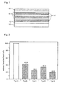
- Figur 2
- den relativen Verschleiß eines Kolbenrings mit verschiedenen Beschichtungen.
- Wie aus
fig. 1 hervorgeht, ist auf dem Grundwerkstoff 10 des Kolbenrings zunächst eine Chrom-Haftschicht 12 aufgebracht. Darauf sind von innen nach außen alternierend mehrere CrN-Schichten 14 und a-C:H:Me-Schichten 16 aufgebracht. Die äußerste Schicht wird durch eine a-C:H-Schicht gebildet. Bei dem gezeigten Beispiel ist diese auf einer DLC-Schicht aufgebracht, sie kann jedoch ebenso auf einer CrN-Schicht aufgetragen werden. - Mit einem derartigen Aufbau wurden Versuche mit Vergleichsbeispielen durchgeführt. Die Tabelle zeigt die verwendeten Schichtsysteme.
Variante Schichtaufbau Substrat ← → Lauffläche Haftschicht Unterbau Zwischenschicht Topschicht A Unbeschichtet - - - - B DLC double layer 01 Cr - a-C:H-01 C DLC double layer 02 Cr - Me(CN)x a-C:H-02 D DLC double layer 3 Cr CrN Cr a-C:H E Multilayer DLC Cr CrN / a-C:H:W alternierend a-C:H - Diese Schichtsysteme wurden auf einen Kolbenring aufgebracht, und es wurde das tribologische Verhalten in Kombination mit einer gehonten Grauguss-Zylinderlaufbuchse in geschmiertem Zustand untersucht. Das Schichtsystem, das den größten Verschleiß aufweist, wird mit 100 % definiert. Aus
Fig. 2 wird zum einen deutlich, dass durch eine DLC-Beschichtung, verglichen mit einer unbeschichteten Oberfläche, der Verschleiß um über 50 % reduziert wird. Das erfindungsgemäße Schichtsystem (Typ E) weist den geringsten relativen Verschleiß auf. Dies wird nach ersten Erkenntnissen durch den stabileren Aufbau des Mehrschichtsystems und das dadurch optimierte Reib- und Verschleißverhalten erreicht.
Claims (10)
- Kolbenring, bevorzugt aus Gusseisen oder Stahl, mit einer Beschichtung, die alternierend mehrere Lagen von CrN-(14) und a-C:H:Me-Schichten (16) aufweist.
- Kolbenring nach Anspruch 1, dadurch gekennzeichnet, dass auf ein Substrat (10) des Kolbenrings eine Haftschicht aus Chrom (12) aufgebracht ist, die vorzugsweise 0,01 bis 1,0 µm dick ist.
- Kolbenring nach Anspruch 1 oder 2, dadurch gekennzeichnet, dass die innerste der alternierenden Lagen eine CrN-Schicht (14) ist.
- Kolbenring nach einem der vorangehenden Ansprüche, dadurch gekennzeichnet, dass die äusserste Schicht der Beschichtung eine a-C:H-Schicht (18) bevorzugt mit einer Dicke von 0,1 bis 5,0 µm ist.
- Kolbenring nach einem der vorangehenden Ansprüche, dadurch gekennzeichnet, dass die CrN- und/oder a-C:H:Me-Lagen eine Dicke von jeweils 50 nm bis 400 nm aufweisen.
- Kolbenring nach einem der vorangehenden Ansprüche, dadurch gekennzeichnet, dass die Beschichtung insgesamt eine Dicke von 2 bis 40 µm aufweist.
- Kolbenring nach einem der vorangehenden Ansprüche, dadurch gekennzeichnet, dass die Härte der CrN-Schicht bei 800-1900 HV 0,002 und/oder die Härte der metallfreien DLC-Schicht bei 1700-2900 HV 0,002 und/oder die Härte der metallhaltigen DLC-Schicht bei 800-1600 HV 0,002 liegt.
- Kolbenring nach einem der vorangehenden Ansprüche, dadurch gekennzeichnet, dass zumindest eine DLC-Schicht metallisch aufgedampft und/oder die metallhaltige und/oder die metallfreie DLC-Schicht mittels PA-CVD-Verfahren hergestellt ist.
- Verfahren zur Beschichtung eines Kolbenrings, bevorzugt aus Gusseisen oder Stahl, bei dem mehrere Lagen von CrN-und a-C:H:Me-Schichten alternierend aufgebracht werden.
- Verfahren nach Anspruch 9, dadurch gekennzeichnet, dass die Beschichtung durch eine Kombination aus Sputtern und PA-CVD erzeugt wird.
Applications Claiming Priority (2)
| Application Number | Priority Date | Filing Date | Title |
|---|---|---|---|
| DE201010002686 DE102010002686A1 (de) | 2010-03-09 | 2010-03-09 | Gleitelement, insbesondere Kolbenring, und Verfahren zur Beschichtung eines Gleitelements |
| PCT/EP2011/052345 WO2011110413A1 (de) | 2010-03-09 | 2011-02-17 | Gleitelement, insbesondere kolbenring, und verfahren zur beschichtung eines gleitelements |
Publications (2)
| Publication Number | Publication Date |
|---|---|
| EP2545202A1 EP2545202A1 (de) | 2013-01-16 |
| EP2545202B1 true EP2545202B1 (de) | 2014-09-03 |
Family
ID=44025838
Family Applications (1)
| Application Number | Title | Priority Date | Filing Date |
|---|---|---|---|
| EP11704223.4A Active EP2545202B1 (de) | 2010-03-09 | 2011-02-17 | Kolbenring, und verfahren zur beschichtung eines kolbenrings |
Country Status (10)
| Country | Link |
|---|---|
| US (1) | US9103015B2 (de) |
| EP (1) | EP2545202B1 (de) |
| JP (1) | JP5901546B2 (de) |
| KR (1) | KR101711844B1 (de) |
| CN (1) | CN102770584B (de) |
| BR (1) | BR112012022007B1 (de) |
| DE (1) | DE102010002686A1 (de) |
| PT (1) | PT2545202E (de) |
| RU (1) | RU2558024C2 (de) |
| WO (1) | WO2011110413A1 (de) |
Cited By (1)
| Publication number | Priority date | Publication date | Assignee | Title |
|---|---|---|---|---|
| WO2020212582A1 (de) * | 2019-04-17 | 2020-10-22 | Oerlikon Surface Solutions Ag, Pfäffikon | Werkstückträgereinrichtung, verfahren zur beschichtung eines werkstücks und werkstück |
Families Citing this family (24)
| Publication number | Priority date | Publication date | Assignee | Title |
|---|---|---|---|---|
| DE102006046915C5 (de) * | 2006-10-04 | 2015-09-03 | Federal-Mogul Burscheid Gmbh | Kolbenring für Verbrennungskraftmaschinen |
| DE102006046917C5 (de) * | 2006-10-04 | 2014-03-20 | Federal-Mogul Burscheid Gmbh | Kolbenring für Verbrennungskraftmaschinen |
| FR2981728B1 (fr) * | 2011-10-21 | 2014-07-04 | Hydromecanique & Frottement | Piece de frottement fonctionnant en milieu lubrifie |
| BRPI1105714B1 (pt) * | 2011-12-07 | 2021-01-05 | Mahle Metal Leve S/A | componente deslizante para uso em motores de combustão interna |
| AT511605B1 (de) * | 2011-12-12 | 2013-01-15 | High Tech Coatings Gmbh | Kohlenstoffbasierende beschichtung |
| BR102012003607A2 (pt) | 2012-02-16 | 2013-10-29 | Mahle Metal Leve Sa | Componente deslizante para uso em motores de combustão interna |
| PL398554A1 (pl) * | 2012-03-21 | 2013-09-30 | Zaklad Mechaniki Maszyn Bukpol Lagodzinski Spólka Jawna | Sposób wytwarzania listwy prowadzacej i listwa prowadzaca |
| TWI513902B (zh) | 2012-06-19 | 2015-12-21 | Tai Mao Ind Corp | 活塞環之結構 |
| DE102012020757A1 (de) | 2012-10-23 | 2014-05-08 | Mahle International Gmbh | Bauteil mit einer Beschichtung und Verfahren zu seiner Herstellung |
| DE102012020756A1 (de) * | 2012-10-23 | 2014-04-24 | Mahle International Gmbh | Bauteil mit einer Beschichtung und Verfahren zu seiner Herstellung |
| DE102013200846A1 (de) * | 2013-01-21 | 2014-07-24 | Federal-Mogul Burscheid Gmbh | Gleitelement, insbesondere Kolbenring, mit einer Beschichtung |
| US9765726B2 (en) | 2013-03-13 | 2017-09-19 | Federal-Mogul | Cylinder liners with adhesive metallic layers and methods of forming the cylinder liners |
| US9968980B2 (en) * | 2013-07-19 | 2018-05-15 | Oerlikon Surface Solutions Ag, Pfäffikon | Coatings for forming tools |
| JP5965378B2 (ja) * | 2013-10-31 | 2016-08-03 | 株式会社リケン | ピストンリング及びその製造方法 |
| DE102014200607A1 (de) * | 2014-01-15 | 2015-07-16 | Federal-Mogul Burscheid Gmbh | Gleitelement, insbesondere Kolbenring |
| WO2017026043A1 (ja) * | 2015-08-10 | 2017-02-16 | 日本アイ・ティ・エフ株式会社 | ピストンリングおよびその製造方法 |
| CN106467958B (zh) * | 2015-08-21 | 2019-03-15 | 中国科学院宁波材料技术与工程研究所 | 基体表面的富碳碳化铬纳米复合超硬自润滑涂层及其制备方法 |
| JP6343266B2 (ja) * | 2015-09-09 | 2018-06-13 | 株式会社リケン | 摺動部材及びピストンリング |
| US10030773B2 (en) | 2016-03-04 | 2018-07-24 | Mahle International Gmbh | Piston ring |
| BR102016015392A2 (pt) * | 2016-06-30 | 2018-01-16 | Mahle Metal Leve S.A. | Sliding element for internal combustion engines |
| DE102017102059A1 (de) * | 2017-02-02 | 2018-08-02 | Friedrich-Alexander-Universität Erlangen | Schichtsystem und Bauteil |
| DE102017002150A1 (de) * | 2017-03-06 | 2018-09-06 | Rosenberger Hochfrequenztechnik Gmbh & Co. Kg | Elektrisches Kontaktelement |
| BR102017007599B1 (pt) * | 2017-04-12 | 2022-07-26 | Mahle Metal Leve S.A. | Anel de pistão para motores de combustão interna |
| RU2687788C1 (ru) * | 2018-12-07 | 2019-05-16 | Акционерное общество "Дальневосточная генерирующая компания" | Многослойное эрозионностойкое покрытие |
Citations (1)
| Publication number | Priority date | Publication date | Assignee | Title |
|---|---|---|---|---|
| JP2003247060A (ja) * | 2001-12-17 | 2003-09-05 | Sumitomo Electric Ind Ltd | 非晶質炭素被膜の製造方法及び非晶質炭素被覆摺動部品 |
Family Cites Families (20)
| Publication number | Priority date | Publication date | Assignee | Title |
|---|---|---|---|---|
| SE442305B (sv) * | 1984-06-27 | 1985-12-16 | Santrade Ltd | Forfarande for kemisk gasutfellning (cvd) for framstellning av en diamantbelagd sammansatt kropp samt anvendning av kroppen |
| US4619865A (en) * | 1984-07-02 | 1986-10-28 | Energy Conversion Devices, Inc. | Multilayer coating and method |
| JPH03291379A (ja) * | 1990-04-10 | 1991-12-20 | Citizen Watch Co Ltd | カーボン硬質膜の積層構造 |
| DK174241B1 (da) | 1996-12-05 | 2002-10-14 | Man B & W Diesel As | Cylinderelement, såsom en cylinderforing, et stempel, et stempelskørt eller en stempelring, i en forbrændingsmotor af dieseltypen samt en stempelring til en sådan motor. |
| JP3561611B2 (ja) * | 1997-09-25 | 2004-09-02 | 三洋電機株式会社 | 硬質炭素系被膜 |
| JPH10237627A (ja) * | 1997-02-24 | 1998-09-08 | Sumitomo Electric Ind Ltd | 硬質炭素膜被覆部材 |
| US6372303B1 (en) * | 1997-06-16 | 2002-04-16 | Robert Bosch Gmbh | Method and device for vacuum-coating a substrate |
| JP3829017B2 (ja) | 1998-08-24 | 2006-10-04 | デュポン神東・オートモティブ・システムズ株式会社 | 電着塗装方法および電着塗装装置 |
| JP3355145B2 (ja) | 1999-02-23 | 2002-12-09 | ダイカ株式会社 | 磁性粒体吸着状態検出及び報知装置 |
| DE10005614A1 (de) * | 2000-02-09 | 2001-08-16 | Hauzer Techno Coating Europ B | Verfahren zur Herstellung von Beschichtungen sowie Gegenstand |
| DE10130308B4 (de) | 2001-06-22 | 2005-05-12 | Thyssenkrupp Electrical Steel Ebg Gmbh | Kornorientiertes Elektroblech mit einer elektrisch isolierenden Beschichtung |
| JP4374153B2 (ja) * | 2001-06-29 | 2009-12-02 | 日本ピストンリング株式会社 | ピストンリング |
| WO2003091474A1 (de) | 2002-04-25 | 2003-11-06 | Unaxis Balzers Ag | Strukturiertes schichtsystem |
| CN101208461B (zh) | 2005-05-26 | 2011-07-06 | 萨尔泽曼塔普拉斯有限公司 | 具有多层硬质涂层的活塞环 |
| US7947372B2 (en) | 2005-08-18 | 2011-05-24 | Sulzer Metaplas Gmbh | Substrate coated with a layered structure comprising a tetrahedral carbon layer and a softer outer layer |
| DE102005063123B3 (de) | 2005-12-30 | 2007-05-31 | Federal-Mogul Burscheid Gmbh | Gleitelement, insbesondere Kolbenring, Verfahren zur Herstellung eines Gleitelements, Gleitsystem und Beschichtung für ein Gleitelement |
| AT503288B1 (de) * | 2006-07-26 | 2007-09-15 | Bosch Gmbh Robert | Verfahren zum aufbringen eines beschichtungsmaterials sowie beschichtung für eine metallische oberfläche |
| DE102006046917C5 (de) | 2006-10-04 | 2014-03-20 | Federal-Mogul Burscheid Gmbh | Kolbenring für Verbrennungskraftmaschinen |
| JP2008286354A (ja) * | 2007-05-21 | 2008-11-27 | Nippon Piston Ring Co Ltd | 摺動部材 |
| DE102008016864B3 (de) | 2008-04-02 | 2009-10-22 | Federal-Mogul Burscheid Gmbh | Kolbenring |
-
2010
- 2010-03-09 DE DE201010002686 patent/DE102010002686A1/de not_active Withdrawn
-
2011
- 2011-02-17 KR KR1020127025302A patent/KR101711844B1/ko active IP Right Grant
- 2011-02-17 US US13/583,690 patent/US9103015B2/en active Active
- 2011-02-17 EP EP11704223.4A patent/EP2545202B1/de active Active
- 2011-02-17 JP JP2012556432A patent/JP5901546B2/ja active Active
- 2011-02-17 PT PT117042234T patent/PT2545202E/pt unknown
- 2011-02-17 BR BR112012022007-1A patent/BR112012022007B1/pt active IP Right Grant
- 2011-02-17 WO PCT/EP2011/052345 patent/WO2011110413A1/de active Application Filing
- 2011-02-17 CN CN201180010789.3A patent/CN102770584B/zh active Active
- 2011-02-17 RU RU2012142813/02A patent/RU2558024C2/ru not_active IP Right Cessation
Patent Citations (1)
| Publication number | Priority date | Publication date | Assignee | Title |
|---|---|---|---|---|
| JP2003247060A (ja) * | 2001-12-17 | 2003-09-05 | Sumitomo Electric Ind Ltd | 非晶質炭素被膜の製造方法及び非晶質炭素被覆摺動部品 |
Cited By (1)
| Publication number | Priority date | Publication date | Assignee | Title |
|---|---|---|---|---|
| WO2020212582A1 (de) * | 2019-04-17 | 2020-10-22 | Oerlikon Surface Solutions Ag, Pfäffikon | Werkstückträgereinrichtung, verfahren zur beschichtung eines werkstücks und werkstück |
Also Published As
| Publication number | Publication date |
|---|---|
| BR112012022007B1 (pt) | 2019-06-11 |
| US9103015B2 (en) | 2015-08-11 |
| JP2013521413A (ja) | 2013-06-10 |
| PT2545202E (pt) | 2014-10-13 |
| RU2558024C2 (ru) | 2015-07-27 |
| WO2011110413A1 (de) | 2011-09-15 |
| KR101711844B1 (ko) | 2017-03-03 |
| JP5901546B2 (ja) | 2016-04-13 |
| KR20130048719A (ko) | 2013-05-10 |
| RU2012142813A (ru) | 2014-04-20 |
| CN102770584A (zh) | 2012-11-07 |
| CN102770584B (zh) | 2016-08-03 |
| EP2545202A1 (de) | 2013-01-16 |
| US20130004756A1 (en) | 2013-01-03 |
| BR112012022007A2 (pt) | 2016-07-19 |
| DE102010002686A1 (de) | 2011-09-15 |
Similar Documents
| Publication | Publication Date | Title |
|---|---|---|
| EP2545202B1 (de) | Kolbenring, und verfahren zur beschichtung eines kolbenrings | |
| DE102009046281B3 (de) | Gleitelement, insbesondere Kolbenring, und Kombination eines Gleitelements mit einem Laufpartner | |
| EP2464761B1 (de) | Kolbenring mit einer beschichtung. | |
| EP1966524B2 (de) | Gleitelement, insbesondere kolbenring, verfahren zur herstellung eines gleitelements, gleitsystem und beschichtung für ein gleitelement | |
| EP2257654B1 (de) | Kolbenring | |
| EP1774053B1 (de) | Verfahren zur erzeugung einer beschichtung auf einem kolbenring sowie kolbenring | |
| AT502546B1 (de) | Lagerelement | |
| EP2331728B1 (de) | Gleitelement in einem verbrennungsmotor, insbesondere kolbenring | |
| EP2946030B1 (de) | Gleitelement, insbesondere kolbenring, mit einer beschichtung | |
| WO2012072483A1 (de) | Gleitelement, insbesondere kolbenring, mit einer beschichtung | |
| EP3186408A1 (de) | Beschichtung für metallbauteile, verfahren zum beschichten eines metallbauteils, kolben für verbrennungskraftmaschinen und kfz | |
| EP0759519B1 (de) | Kolbenring für Verbrennungsmotoren | |
| DE112017003285T5 (de) | Gleitelement für Verbrennungsmotoren | |
| EP2545201B1 (de) | Schraubendruckfeder für einen ölabstreifring eines kolbens in einem verbrennungsmotor und verfahren zur beschichtung einer schraubendruckfeder | |
| EP2408949B1 (de) | Verfahren zur beschichtung eines gleitelements und gleitelement, insbesondere kolbenring | |
| EP3116678B1 (de) | Lichtbogendrahtgespritze schicht auf der laufbahn eines zylinderkurbelgehäuses aus einer aluminiumlegierung | |
| DE102016108088B4 (de) | Beschichteter Kolbenring mit Schutzschicht | |
| DE102012207813A1 (de) | Gleitkörper mit Beschichtung | |
| DE10212299B4 (de) | Verfahren zur Aufbringung thermischer Spritzschichten auf galvanisch beschichtete Kolbenringe sowie ein nach dem Verfahren hergestellter Kolbenring | |
| DE10014515C2 (de) | Kolbenring mit Verschleißschutzschicht sowie Verschleißschutzschicht für einen Kolbenring | |
| DE10320979B4 (de) | Kolben für einen Verbrennungsmotor und Verfahren zur Beschichtung eines Kolbens für einen Verbrennungsmotor |
Legal Events
| Date | Code | Title | Description |
|---|---|---|---|
| PUAI | Public reference made under article 153(3) epc to a published international application that has entered the european phase |
Free format text: ORIGINAL CODE: 0009012 |
|
| 17P | Request for examination filed |
Effective date: 20120810 |
|
| AK | Designated contracting states |
Kind code of ref document: A1 Designated state(s): AL AT BE BG CH CY CZ DE DK EE ES FI FR GB GR HR HU IE IS IT LI LT LU LV MC MK MT NL NO PL PT RO RS SE SI SK SM TR |
|
| DAX | Request for extension of the european patent (deleted) | ||
| 17Q | First examination report despatched |
Effective date: 20130910 |
|
| GRAP | Despatch of communication of intention to grant a patent |
Free format text: ORIGINAL CODE: EPIDOSNIGR1 |
|
| INTG | Intention to grant announced |
Effective date: 20140411 |
|
| GRAS | Grant fee paid |
Free format text: ORIGINAL CODE: EPIDOSNIGR3 |
|
| GRAA | (expected) grant |
Free format text: ORIGINAL CODE: 0009210 |
|
| AK | Designated contracting states |
Kind code of ref document: B1 Designated state(s): AL AT BE BG CH CY CZ DE DK EE ES FI FR GB GR HR HU IE IS IT LI LT LU LV MC MK MT NL NO PL PT RO RS SE SI SK SM TR |
|
| REG | Reference to a national code |
Ref country code: GB Ref legal event code: FG4D Free format text: NOT ENGLISH |
|
| REG | Reference to a national code |
Ref country code: CH Ref legal event code: EP Ref country code: AT Ref legal event code: REF Ref document number: 685674 Country of ref document: AT Kind code of ref document: T Effective date: 20140915 |
|
| REG | Reference to a national code |
Ref country code: IE Ref legal event code: FG4D Free format text: LANGUAGE OF EP DOCUMENT: GERMAN |
|
| REG | Reference to a national code |
Ref country code: PT Ref legal event code: SC4A Free format text: AVAILABILITY OF NATIONAL TRANSLATION Effective date: 20141001 |
|
| REG | Reference to a national code |
Ref country code: DE Ref legal event code: R096 Ref document number: 502011004257 Country of ref document: DE Effective date: 20141016 |
|
| REG | Reference to a national code |
Ref country code: SE Ref legal event code: TRGR |
|
| PG25 | Lapsed in a contracting state [announced via postgrant information from national office to epo] |
Ref country code: ES Free format text: LAPSE BECAUSE OF FAILURE TO SUBMIT A TRANSLATION OF THE DESCRIPTION OR TO PAY THE FEE WITHIN THE PRESCRIBED TIME-LIMIT Effective date: 20140903 Ref country code: GR Free format text: LAPSE BECAUSE OF FAILURE TO SUBMIT A TRANSLATION OF THE DESCRIPTION OR TO PAY THE FEE WITHIN THE PRESCRIBED TIME-LIMIT Effective date: 20141204 Ref country code: FI Free format text: LAPSE BECAUSE OF FAILURE TO SUBMIT A TRANSLATION OF THE DESCRIPTION OR TO PAY THE FEE WITHIN THE PRESCRIBED TIME-LIMIT Effective date: 20140903 Ref country code: NO Free format text: LAPSE BECAUSE OF FAILURE TO SUBMIT A TRANSLATION OF THE DESCRIPTION OR TO PAY THE FEE WITHIN THE PRESCRIBED TIME-LIMIT Effective date: 20141203 Ref country code: LT Free format text: LAPSE BECAUSE OF FAILURE TO SUBMIT A TRANSLATION OF THE DESCRIPTION OR TO PAY THE FEE WITHIN THE PRESCRIBED TIME-LIMIT Effective date: 20140903 |
|
| REG | Reference to a national code |
Ref country code: NL Ref legal event code: VDEP Effective date: 20140903 |
|
| REG | Reference to a national code |
Ref country code: LT Ref legal event code: MG4D |
|
| PG25 | Lapsed in a contracting state [announced via postgrant information from national office to epo] |
Ref country code: RS Free format text: LAPSE BECAUSE OF FAILURE TO SUBMIT A TRANSLATION OF THE DESCRIPTION OR TO PAY THE FEE WITHIN THE PRESCRIBED TIME-LIMIT Effective date: 20140903 Ref country code: CY Free format text: LAPSE BECAUSE OF FAILURE TO SUBMIT A TRANSLATION OF THE DESCRIPTION OR TO PAY THE FEE WITHIN THE PRESCRIBED TIME-LIMIT Effective date: 20140903 Ref country code: LV Free format text: LAPSE BECAUSE OF FAILURE TO SUBMIT A TRANSLATION OF THE DESCRIPTION OR TO PAY THE FEE WITHIN THE PRESCRIBED TIME-LIMIT Effective date: 20140903 Ref country code: HR Free format text: LAPSE BECAUSE OF FAILURE TO SUBMIT A TRANSLATION OF THE DESCRIPTION OR TO PAY THE FEE WITHIN THE PRESCRIBED TIME-LIMIT Effective date: 20140903 |
|
| PG25 | Lapsed in a contracting state [announced via postgrant information from national office to epo] |
Ref country code: NL Free format text: LAPSE BECAUSE OF FAILURE TO SUBMIT A TRANSLATION OF THE DESCRIPTION OR TO PAY THE FEE WITHIN THE PRESCRIBED TIME-LIMIT Effective date: 20140903 |
|
| PG25 | Lapsed in a contracting state [announced via postgrant information from national office to epo] |
Ref country code: EE Free format text: LAPSE BECAUSE OF FAILURE TO SUBMIT A TRANSLATION OF THE DESCRIPTION OR TO PAY THE FEE WITHIN THE PRESCRIBED TIME-LIMIT Effective date: 20140903 Ref country code: RO Free format text: LAPSE BECAUSE OF FAILURE TO SUBMIT A TRANSLATION OF THE DESCRIPTION OR TO PAY THE FEE WITHIN THE PRESCRIBED TIME-LIMIT Effective date: 20140903 Ref country code: CZ Free format text: LAPSE BECAUSE OF FAILURE TO SUBMIT A TRANSLATION OF THE DESCRIPTION OR TO PAY THE FEE WITHIN THE PRESCRIBED TIME-LIMIT Effective date: 20140903 Ref country code: SK Free format text: LAPSE BECAUSE OF FAILURE TO SUBMIT A TRANSLATION OF THE DESCRIPTION OR TO PAY THE FEE WITHIN THE PRESCRIBED TIME-LIMIT Effective date: 20140903 Ref country code: IS Free format text: LAPSE BECAUSE OF FAILURE TO SUBMIT A TRANSLATION OF THE DESCRIPTION OR TO PAY THE FEE WITHIN THE PRESCRIBED TIME-LIMIT Effective date: 20150103 |
|
| PG25 | Lapsed in a contracting state [announced via postgrant information from national office to epo] |
Ref country code: PL Free format text: LAPSE BECAUSE OF FAILURE TO SUBMIT A TRANSLATION OF THE DESCRIPTION OR TO PAY THE FEE WITHIN THE PRESCRIBED TIME-LIMIT Effective date: 20140903 |
|
| REG | Reference to a national code |
Ref country code: DE Ref legal event code: R097 Ref document number: 502011004257 Country of ref document: DE |
|
| PG25 | Lapsed in a contracting state [announced via postgrant information from national office to epo] |
Ref country code: BE Free format text: LAPSE BECAUSE OF NON-PAYMENT OF DUE FEES Effective date: 20150228 |
|
| PLBE | No opposition filed within time limit |
Free format text: ORIGINAL CODE: 0009261 |
|
| STAA | Information on the status of an ep patent application or granted ep patent |
Free format text: STATUS: NO OPPOSITION FILED WITHIN TIME LIMIT |
|
| PG25 | Lapsed in a contracting state [announced via postgrant information from national office to epo] |
Ref country code: DK Free format text: LAPSE BECAUSE OF FAILURE TO SUBMIT A TRANSLATION OF THE DESCRIPTION OR TO PAY THE FEE WITHIN THE PRESCRIBED TIME-LIMIT Effective date: 20140903 |
|
| 26N | No opposition filed |
Effective date: 20150604 |
|
| PG25 | Lapsed in a contracting state [announced via postgrant information from national office to epo] |
Ref country code: LU Free format text: LAPSE BECAUSE OF FAILURE TO SUBMIT A TRANSLATION OF THE DESCRIPTION OR TO PAY THE FEE WITHIN THE PRESCRIBED TIME-LIMIT Effective date: 20150217 |
|
| REG | Reference to a national code |
Ref country code: CH Ref legal event code: PL |
|
| PG25 | Lapsed in a contracting state [announced via postgrant information from national office to epo] |
Ref country code: LI Free format text: LAPSE BECAUSE OF NON-PAYMENT OF DUE FEES Effective date: 20150228 Ref country code: CH Free format text: LAPSE BECAUSE OF NON-PAYMENT OF DUE FEES Effective date: 20150228 Ref country code: MC Free format text: LAPSE BECAUSE OF FAILURE TO SUBMIT A TRANSLATION OF THE DESCRIPTION OR TO PAY THE FEE WITHIN THE PRESCRIBED TIME-LIMIT Effective date: 20140903 |
|
| REG | Reference to a national code |
Ref country code: IE Ref legal event code: MM4A |
|
| PG25 | Lapsed in a contracting state [announced via postgrant information from national office to epo] |
Ref country code: SI Free format text: LAPSE BECAUSE OF FAILURE TO SUBMIT A TRANSLATION OF THE DESCRIPTION OR TO PAY THE FEE WITHIN THE PRESCRIBED TIME-LIMIT Effective date: 20140903 |
|
| REG | Reference to a national code |
Ref country code: FR Ref legal event code: PLFP Year of fee payment: 6 |
|
| PG25 | Lapsed in a contracting state [announced via postgrant information from national office to epo] |
Ref country code: IE Free format text: LAPSE BECAUSE OF NON-PAYMENT OF DUE FEES Effective date: 20150217 |
|
| PG25 | Lapsed in a contracting state [announced via postgrant information from national office to epo] |
Ref country code: MT Free format text: LAPSE BECAUSE OF FAILURE TO SUBMIT A TRANSLATION OF THE DESCRIPTION OR TO PAY THE FEE WITHIN THE PRESCRIBED TIME-LIMIT Effective date: 20140903 |
|
| REG | Reference to a national code |
Ref country code: FR Ref legal event code: PLFP Year of fee payment: 7 |
|
| PG25 | Lapsed in a contracting state [announced via postgrant information from national office to epo] |
Ref country code: BG Free format text: LAPSE BECAUSE OF FAILURE TO SUBMIT A TRANSLATION OF THE DESCRIPTION OR TO PAY THE FEE WITHIN THE PRESCRIBED TIME-LIMIT Effective date: 20140903 Ref country code: HU Free format text: LAPSE BECAUSE OF FAILURE TO SUBMIT A TRANSLATION OF THE DESCRIPTION OR TO PAY THE FEE WITHIN THE PRESCRIBED TIME-LIMIT; INVALID AB INITIO Effective date: 20110217 Ref country code: SM Free format text: LAPSE BECAUSE OF FAILURE TO SUBMIT A TRANSLATION OF THE DESCRIPTION OR TO PAY THE FEE WITHIN THE PRESCRIBED TIME-LIMIT Effective date: 20140903 |
|
| PG25 | Lapsed in a contracting state [announced via postgrant information from national office to epo] |
Ref country code: TR Free format text: LAPSE BECAUSE OF FAILURE TO SUBMIT A TRANSLATION OF THE DESCRIPTION OR TO PAY THE FEE WITHIN THE PRESCRIBED TIME-LIMIT Effective date: 20140903 |
|
| REG | Reference to a national code |
Ref country code: FR Ref legal event code: PLFP Year of fee payment: 8 |
|
| PG25 | Lapsed in a contracting state [announced via postgrant information from national office to epo] |
Ref country code: MK Free format text: LAPSE BECAUSE OF FAILURE TO SUBMIT A TRANSLATION OF THE DESCRIPTION OR TO PAY THE FEE WITHIN THE PRESCRIBED TIME-LIMIT Effective date: 20140903 |
|
| PG25 | Lapsed in a contracting state [announced via postgrant information from national office to epo] |
Ref country code: AL Free format text: LAPSE BECAUSE OF FAILURE TO SUBMIT A TRANSLATION OF THE DESCRIPTION OR TO PAY THE FEE WITHIN THE PRESCRIBED TIME-LIMIT Effective date: 20140903 |
|
| PGFP | Annual fee paid to national office [announced via postgrant information from national office to epo] |
Ref country code: IT Payment date: 20190213 Year of fee payment: 9 Ref country code: GB Payment date: 20190128 Year of fee payment: 9 |
|
| PGFP | Annual fee paid to national office [announced via postgrant information from national office to epo] |
Ref country code: FR Payment date: 20200124 Year of fee payment: 10 |
|
| REG | Reference to a national code |
Ref country code: AT Ref legal event code: MM01 Ref document number: 685674 Country of ref document: AT Kind code of ref document: T Effective date: 20200217 |
|
| GBPC | Gb: european patent ceased through non-payment of renewal fee |
Effective date: 20200217 |
|
| PG25 | Lapsed in a contracting state [announced via postgrant information from national office to epo] |
Ref country code: AT Free format text: LAPSE BECAUSE OF NON-PAYMENT OF DUE FEES Effective date: 20200217 |
|
| PG25 | Lapsed in a contracting state [announced via postgrant information from national office to epo] |
Ref country code: GB Free format text: LAPSE BECAUSE OF NON-PAYMENT OF DUE FEES Effective date: 20200217 |
|
| PG25 | Lapsed in a contracting state [announced via postgrant information from national office to epo] |
Ref country code: IT Free format text: LAPSE BECAUSE OF NON-PAYMENT OF DUE FEES Effective date: 20200217 |
|
| PG25 | Lapsed in a contracting state [announced via postgrant information from national office to epo] |
Ref country code: FR Free format text: LAPSE BECAUSE OF NON-PAYMENT OF DUE FEES Effective date: 20210228 |
|
| PGFP | Annual fee paid to national office [announced via postgrant information from national office to epo] |
Ref country code: SE Payment date: 20230119 Year of fee payment: 13 Ref country code: PT Payment date: 20230123 Year of fee payment: 13 Ref country code: DE Payment date: 20230119 Year of fee payment: 13 |
|
| P01 | Opt-out of the competence of the unified patent court (upc) registered |
Effective date: 20230528 |
|
| PGFP | Annual fee paid to national office [announced via postgrant information from national office to epo] |
Ref country code: DE Payment date: 20240123 Year of fee payment: 14 Ref country code: PT Payment date: 20240124 Year of fee payment: 14 |