EP2544210A1 - Fusible électrique avec bornes de restriction de couple - Google Patents
Fusible électrique avec bornes de restriction de couple Download PDFInfo
- Publication number
- EP2544210A1 EP2544210A1 EP12174689A EP12174689A EP2544210A1 EP 2544210 A1 EP2544210 A1 EP 2544210A1 EP 12174689 A EP12174689 A EP 12174689A EP 12174689 A EP12174689 A EP 12174689A EP 2544210 A1 EP2544210 A1 EP 2544210A1
- Authority
- EP
- European Patent Office
- Prior art keywords
- fuse
- fuse element
- electrical
- housing
- electrical fuse
- Prior art date
- Legal status (The legal status is an assumption and is not a legal conclusion. Google has not performed a legal analysis and makes no representation as to the accuracy of the status listed.)
- Withdrawn
Links
Images
Classifications
-
- H—ELECTRICITY
- H01—ELECTRIC ELEMENTS
- H01H—ELECTRIC SWITCHES; RELAYS; SELECTORS; EMERGENCY PROTECTIVE DEVICES
- H01H85/00—Protective devices in which the current flows through a part of fusible material and this current is interrupted by displacement of the fusible material when this current becomes excessive
- H01H85/02—Details
- H01H85/04—Fuses, i.e. expendable parts of the protective device, e.g. cartridges
- H01H85/05—Component parts thereof
- H01H85/143—Electrical contacts; Fastening fusible members to such contacts
-
- H—ELECTRICITY
- H01—ELECTRIC ELEMENTS
- H01H—ELECTRIC SWITCHES; RELAYS; SELECTORS; EMERGENCY PROTECTIVE DEVICES
- H01H85/00—Protective devices in which the current flows through a part of fusible material and this current is interrupted by displacement of the fusible material when this current becomes excessive
- H01H85/0013—Means for preventing damage, e.g. by ambient influences to the fuse
-
- H—ELECTRICITY
- H01—ELECTRIC ELEMENTS
- H01H—ELECTRIC SWITCHES; RELAYS; SELECTORS; EMERGENCY PROTECTIVE DEVICES
- H01H85/00—Protective devices in which the current flows through a part of fusible material and this current is interrupted by displacement of the fusible material when this current becomes excessive
- H01H85/02—Details
- H01H85/04—Fuses, i.e. expendable parts of the protective device, e.g. cartridges
- H01H85/05—Component parts thereof
- H01H85/143—Electrical contacts; Fastening fusible members to such contacts
- H01H85/15—Screw-in contacts
-
- H—ELECTRICITY
- H01—ELECTRIC ELEMENTS
- H01H—ELECTRIC SWITCHES; RELAYS; SELECTORS; EMERGENCY PROTECTIVE DEVICES
- H01H85/00—Protective devices in which the current flows through a part of fusible material and this current is interrupted by displacement of the fusible material when this current becomes excessive
- H01H85/02—Details
- H01H85/04—Fuses, i.e. expendable parts of the protective device, e.g. cartridges
- H01H85/05—Component parts thereof
- H01H85/165—Casings
-
- H—ELECTRICITY
- H01—ELECTRIC ELEMENTS
- H01H—ELECTRIC SWITCHES; RELAYS; SELECTORS; EMERGENCY PROTECTIVE DEVICES
- H01H85/00—Protective devices in which the current flows through a part of fusible material and this current is interrupted by displacement of the fusible material when this current becomes excessive
- H01H85/02—Details
- H01H85/04—Fuses, i.e. expendable parts of the protective device, e.g. cartridges
- H01H85/05—Component parts thereof
- H01H85/055—Fusible members
- H01H85/08—Fusible members characterised by the shape or form of the fusible member
- H01H85/10—Fusible members characterised by the shape or form of the fusible member with constriction for localised fusing
Definitions
- the field of the invention relates generally to electrical fuses, and more specifically to electrical fuses having terminals that are bolted to electrical circuit conductors.
- Fuses are overcurrent protection devices for electrical circuitry, and are widely used to protect electrical power systems and prevent damage to circuitry and associated components when specified circuit conditions occur.
- a fusible element or assembly is coupled between terminal elements of the fuse, and when specified current conditions occur, the fusible element or assembly, disintegrates, melts or otherwise structurally fails and opens a current path between the fuse terminals.
- Line side circuitry may therefore be electrically isolated from load side circuitry through the fuse, preventing possible damage to load side circuitry from overcurrent conditions.
- improvements in electrical fuses are desired.
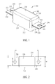
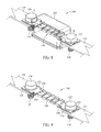
- Figure 1 is a perspective view of an exemplary embodiment of an electrical fuse.
- Figure 2 is a top view of the exemplary electrical fuse shown in Figure 1 .
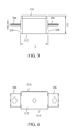
- Figure 3 is a side elevational view of the exemplary electrical fuse shown in Figures 1 and 2 .
- Figure 4 is a bottom view of the exemplary electrical fuse shown in Figures 1-3 .
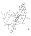
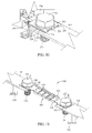
- Figure 5 is an exploded view of the electrical fuse shown in Figure 1 .
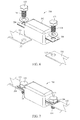
- Figure 6 illustrates the electrical fuse shown in Figure 1 being installed to circuit conductors with bolted connections.
- Figure 7 shows the electrical fuse of Figure 6 installed to the conductors.
- Figure 8 illustrates the installed electrical fuse of Figure 7 with internal components shown.
- Figure 9 illustrates a portion of the installed electrical fuse shown in Figure 7 .
- Figure 10 is a magnified view of a portion of the electrical fuse shown in Figure 7 .
- Figure 11 illustrates a connection of a fuse element to circuit conductors.
- the electrical fuses are preferably bolted directly to circuit conductors in the power system.
- This connection method provides the best condition for any heating of the fuse in operation to be liberated into the circuit conductors and connectors.
- the bolting of the fuse directly to the circuit conductors can pose mechanical damage to the fragile features of the fuse element.
- bolt torque as the fuse is mechanically connected to the circuit conductors can damage, the fragile, current-limiting features of the fuse element at a location internal to the fuse. As such damage that may occur can be difficult to predict or detect from the perspective of an installer or person servicing the electrical power system in use.
- FIG 11 illustrates an exemplary fuse element 100 capable of satisfactorily operating at higher voltages of, for example, an electrical power system associated with an electric powered vehicle.
- the fuse element 100 is fabricated from a generally elongated conductor body 102 having opposite ends 104 and 106.
- the ends 104 and 106 in the exemplary embodiment shown are generally planar elements that define connection tabs extending longitudinally from either side of a fuse element portion 108.
- the fuse element portion 108 include a number of openings 110 formed therethrough that define current-limiting areas of reduced cross sectional area, sometimes referred to as weak spots.
- the number and arrangement of the weak spots may be varied in other embodiments, but are strategically selected such that the fuse element portion 110 melts, disintegrates, breaks or otherwise structurally fails when electrical current flowing through the fuse element portion 108 reaches a predetermined limit. This is referred to an "opening" of the fuse because the conductive path through the fuse element portion 110 can no longer conduct current and an open circuit condition results.
- the fuse element can reliably open in response to a specified current condition (e.g., an overcurrent condition) at one or more locations in the fuse element portion 108, typically at one or more locations adjacent to the weak spots.
- a specified current condition e.g., an overcurrent condition
- the weak spot openings 110 therefore affect not only the amount of current that the fuse element portion 108 can withstand, but to a large extent determine the most likely location(s) that the fuse element portion 108 will actually open in response to current conditions. While an exemplary arrangement of weak spot openings 110 is shown, other arrangements are, of course possible.
- the fuse element 100 may be fabricated from a substantially planar strip of conductive material according to known techniques. Additionally, and as shown in Figure 11 , the fuse element portion 108 may be formed with a first edge 112 that is bent out of the plane of the conductive body 102. In the exemplary embodiment illustrated, the first edge 112 extends substantially perpendicularly or normal to the plane of the conductor body 102, and extends in first direction shown in Figure 11 as an upward direction. The fuse element portion 108 may likewise be formed with a second edge 114 that is also bent out of the plane of the conductive body 102.
- the second edge 114 extends substantially perpendicularly or normal to the plane of the conductor body 102, and extends in second direction shown in Figure 11 as a downward direction.
- the edges 112, 114 extend in opposite directions from one another.
- the formed edges 112, 114 increase the capacity of the fuse element 100 while reducing its size measured from lateral edge 112 to lateral edge 114.
- Other geometric variations of the fuse element portion 108 are, of course, possible with similar effect to increase the capacity of the fuse element while still providing a relatively compact size that facilitates a reduction in the size of the fuse.
- the fuse element portions 108 may be entirely planar if desired.
- the weak spot openings 110 reside in part on the planar surface of the conductive body 102 and in part on the respective out of plane edges 112, 114. That is, the out of plane edges 112, 114 are also provided with weak spot openings 110.
- the weak spot openings in the edges 112, 114 shown are a continuation of the pattern provided on the planar surface of the conductive body 102. This need not be the case in other embodiments, however.
- the side edges 112, 114 need not include weak spot openings at all, or could include weak spot openings that are differently arranged from those in the main, planar surface of the conductive body 102.
- fuse element portion 108 Further features may be provided in the fuse element portion 108 as desired. For example, time delay features, m-spot features, and other features familiar to those in the art may be provided to enhance the interruption characteristics as the fuse element 100 opens in response to selected circuit conditions.
- the current capacity of the fuse element 100 is determined principally by the thickness of the conductor body 102 used to fabricate the fuse element 100, the number and arrangement of the weak spot openings 110, and the dimensions of the formed edges 112 and 114.
- the embodiment of the fuse element 100 shown in Figure 11 is suitable for use with an electrical power system for an electric powered vehicle operating at, for example, a voltage of about 450VDC, and can easily withstand relatively high electrical current associated therewith while reliably providing desirable opening characteristics, in response to overcurrent conditions, to isolate load side circuitry 126 and associated power-receiving devices from the line side circuitry 124 and power supply devices.
- the ends 104 and 106 of the fuse element 100 extend in the plane of the conductor body 102 and define connection tabs attachable to respective circuit conductors 116, 118 via fasteners such as bolts 120, 122.
- the conductor 116 may extend to and establish electrical connection with the line side power supply or circuitry 124
- the conductor 118 may extend to and establish electrical connection with the load side power receiving device or circuitry 126.
- electrical current flows from the line side circuitry 124 to and through the circuit conductor 116, from the conductor 116 to and through the fuse element 100, and from the fuse element 100 to and through the conductor 118 to the load side circuitry 126.
- the conductors 116 and 118 are shown as flat conductor bars, a variety of alternative conductors and connectors are possible to make the line and load side electrical connections. Additionally, either of the circuit conductors 116, 118 may be configured as a bus bar and receive electrical power from multiple sources (e.g. multiple batteries of the vehicle), or supply electrical power to multiple loads. In such an embodiment, a single fuse element 100 may provide fusible circuit protection to multiple loads and/or may supply power to a load or loads from more than one power supply source such as multiple storage batteries in an electrical vehicle power system.
- the fragile fuse element portion 108 is highly susceptible to twisting, deformation, and/or fracture that will alter its operating conditions and opening characteristics. Suboptimal fuse operation will result if such damage occurs, and in the unfortunate case wherein the fuse element portion 108 completely breaks so as to sever the conductive path through the fuse element 102 altogether, the fuse element 100 would be rendered completely inoperable.
- a careful installer would perhaps be able to avoid damaging the fuse element 100 via limiting the amount of torque applied to the bolts 120, 122 as the electrical fuse is installed, but considering the potential number of different persons that may at some point install or remove a fuse in a vehicle (e.g., a manufacturer, a dealer, a service technician, and a vehicle owner all having varying amounts of training and experience) human error in advertently applying too much torque to the bolts 120, 122 seems to be inevitable across a large number of vehicles to be manufactured and periodically serviced and maintained.
- a vehicle e.g., a manufacturer, a dealer, a service technician, and a vehicle owner all having varying amounts of training and experience
- the fuse element 100 is typically contained in a housing (not shown in Figure 11 ), if the fuse element 100 is advertently damaged when the fuse is installed, or perhaps even removed, it is unlikely to be detected. Because fuses can be in service (i.e., connected to energized electrical circuitry) for indefinite and lengthy periods of time (e.g., years or even decades) before an overcurrent condition occurs that is sufficient to open the fuse, a suboptimal fuse can result in suboptimal circuit protection for an extended period of time. Considering the expense and sophistication of modem electric vehicles, and the many computerized controls, adequate circuit protection is paramount.
- Figures 1-10 illustrate exemplary embodiments of an electrical fuse assembly that overcome torque related problems as discussed above when connecting the fuse to circuit conductors with fasteners such as bolts.
- this is achieved with terminal elements, separately provided from the fuse element, that are movable relative to the ends of the fuse element, and therefore restrict, if not eliminate, torsional forces from reaching the delicate fuse element portion that is vulnerable to damage.
- terminal elements separately provided from the fuse element, that are movable relative to the ends of the fuse element, and therefore restrict, if not eliminate, torsional forces from reaching the delicate fuse element portion that is vulnerable to damage.
- inventive concepts described below may accrue to other end use applications.
- the benefits of the invention generally accrue to any type of fuse or fuse application that is bolted to circuit conductors, and the electric powered vehicle environment is one such example that is described for the sake of illustration rather than limitation.
- Figures 1-10 illustrate various views of an exemplary embodiment of an electrical fuse 200 including a housing 202 and terminal elements 204, 206 projecting from the housing 200 for bolted connection to circuit conductors such as the conductors 116, 118 described above in relation to Figure 11 .
- the terminal elements 204, 206 in the exemplary embodiments shown are coupled to the fuse element connection tabs 104, 106 ( Figures 5 and 8-10 ) and thus provide electrical connections to the fuse element 100 and the fuse element portion 108 thereof when the bolts 120, 122 are tightened to clamp the terminal elements 204, 206 to the circuit conductors 116, 118.
- Figures 1-4 illustrate the electrical fuse 200 apart from the circuit conductors 116 and 118
- Figure 5 illustrates the electrical fuse 200 in exploded view
- Figures 6-10 illustrate various aspects of connecting the fuse 200 to the circuit conductors 116, 118.
- the fuse housing 202 is fabricated from a generally insulating or nonconductive material, such as heavy duty plastic according to known techniques or another suitable material known in the art.
- the housing 202 is formed into a generally rectangular shape as shown, and includes a top wall 210, a bottom wall 212 opposite the top wall 210, side walls 214 and 216 interconnecting the bottom and top walls 210, and end walls 218, 220 interconnecting the top and bottom walls 210 and 212 and also the side walls 214 and 216.
- the housing 102 therefore defines a box-like enclosure for the fuse element 100 as seen in Figure 5 .
- the exemplary housing 202 shown in Figures 1-4 is relatively compact in size, and has a length L ( Figure 3 ) of about 1.65 inches (42.01 mm), a width W ( Figure 2 ) of about 0.79 inches (20 mm) and a height H ( Figure 3 ) of about 0.79 inches (20 mm).
- the fuse housing 202 advantageously provides a compact package size, and is noticeably smaller than conventional, high voltage fuses that are similarly bolted in place with respect to electrical conductors. It is contemplated, however, that the dimensions of the fuse 200 may be varied for different purposes and as desired. Additionally, while the height H and width W of the housing 202 in the example shown in the Figures is the same, these dimensions need not be the same in other embodiments. For that matter, the housing 202 need not be rectangular in other embodiments. Similar benefits to those described herein can be achieved with non-rectangular housings, included but not limited to cylindrical housings.
- the terminal elements 204 and 206 are generally planar conductive elements formed as sleeves that slip over the fuse element ends 104, 106. That is, in an exemplary embodiment, the terminal elements 204, 206 may be formed from a conductive strip of material that is folded upon itself to form a sleeve that accepts the respective ends 104, 106 of the fuse element 100 as best shown in Figure 5 .
- the terminal elements 204, 206 each accordingly have an upper side 222 and a lower side 224 joined with hinge like connecting sections 226.
- the upper and lower sides 222, 224 are spaced apart by an amount slightly greater than the thickness of the fuse element ends 104, 106 such that the terminal elements 204, 206 may be slipped over the ends 104, 106 of the fuse element 100 with a leading end 228 receiving the fuse element ends 104, 106.
- the upper side 222 overlies an upper surface of the respective fuse element end
- the lower side 224 underlies the lower surface of the respective fuse element end. That is, each fuse element end 104, 106 is sandwiched between the upper side 222 and the lower side 224 of each terminal element 204, 206.
- the terminal elements 204, 206 are substantially identically constructed but are reversed in a mirror-image arrangement on the fuse element ends 104, 106.
- Each terminal element 204, 206 includes a pair of notches 230 formed adjacent the leading end 228, and a fastener opening or through hole 232 extending completely therethrough.
- the notches 230 When assembled as shown in Figures 1-4 and 6-10 , the notches 230 generally align with shoulders 130 ( Figure 5 ) formed in the fuse element ends 104, 106.
- the through hole 232 of each terminal element 204, 206 is aligned with and substantially coincides with a complementary opening or though hole 132 in each end 104, 106 of the fuse element 100.
- the through holes 132, 232 When the through holes 132, 232 are aligned in the assembly, they collectively receive a shank 134 ( Figures 6-10 ) of one to the bolts 120, 122 as the electrical fuse 100 is installed to the circuit conductor 116, 118. Because the terminal elements 204, 206 are only slip-fit to the fuse element ends 104, 106 they are movable relative to the terminal ends 204, and 206. That is, the terminal elements 204, 206 are not fixedly mounted to the fuse elements 104, 106 via soldering, brazing, welding or other techniques commonly used in electrical fuse constructions to connect the fuse element to connecting terminal structure.
- FIG. 5 shows additional details of the housing 202 in an exemplary embodiment.
- the housing 202 may be fabricated from two parts, namely a base 240 and a cover 250.
- the base 240 may define the generally planar bottom wall 212, and end walls 242 may project upwardly from the bottom walls 212.
- the cover 250 is formed with the top wall 210, the side walls 214 and 216, and the end walls 218 and 220.
- the walls 210, 214, 216, 218 and 220 define a hollow, box like interior enclosure 152 that surround and protect the fuse element portion 108.
- the ends walls 218, 220 of the cover 250 include cut outs or openings 254 that receive the end walls 242 of the base 240.
- the terminal elements 204, 206 are coupled to the fuse element ends 104, 106.
- the fuse element 100 including the terminal elements 204, 206 is then placed to extend over the end walls 242 of the base 240 with the notches 230 aligned with the base end walls 242.
- the cover 250 is then placed over the fuse element 200, and the edges of the opening 254 in the cover 250 extend into the notches and capture the terminal elements 204 in place longitudinally.
- the cover openings 254 are dimensioned to receive the end walls 242 of the base and provide a closed, sealed enclosure around the fuse element portion 108 when the base 240 and cover 250 are joined.
- the openings 254 in combination with the notches 230 of the terminal elements 204, 206, creates a clearance that allows the terminal elements 204, 206 to move relative to respective fuse element ends 104, 106. More specifically, the terminal elements 204, 206 may rotate relative to the fuse element ends 104, 106 and also relative to the housing end walls 218, 220 and 242 as the fuse 200 is installed. The notches 230 and the edges of the housing openings 254, however, prevent the terminal elements 204, 206 from being removed from the housing 200.
- the base 240 is formed with a through hole opening 262 that may be used to fill the housing enclosure 152 with an arc quenching media such as silica sand.
- a plug 260 may be provided to plug and seal the opening 262 when the arc quenching media has been introduced in a sufficient amount.
- the assembled fuse 200 may be installed to the circuit conductors 116, 118 as shown in Figures 6-10 .
- the through holes 232 of the terminal elements 204, 206 may be aligned with corresponding through holes 117, 119 in the circuit conductors 116, 118.
- the shanks 134 of the bolts 120, 122 may then be inserted through the holes 232 and 117, 119.
- An optional washer may be utilized to facilitate the connection as shown.
- a nut (not shown) may be applied to the shank 134 of each bolt 120, 122 to clamp the terminal elements 204, 206 to the conductor.
- the bolt shanks 134 may engage the chassis of an electrical powered vehicle, or other supporting structure, as the fuse 102 is mounted.
- any further application of the forces F on the terminal elements 204, 206 is generally applied to the housing 200 at the side edges of the cover openings 254, and is not transmitted to the fuse element portion 108 that is susceptible of being damaged.
- the structurally fragile fuse element portion 108 is largely mechanically isolated from the torque forces F and unlikely to be damaged because of the movable terminal elements 204, 206.
- the torque stresses are distributed more evenly during slippage between the terminal elements 204, 206 and the ends 104, 106 of the fuse element 100.
- the slip fit of the terminal elements 204 and 206 over the fuse element ends 104, 106 effectively acts as a washer to distribute the load evenly and to provide some degree of torque slippage to minimize damage of the fuse element portion 108 during the bolt down installation.
- any torque forces associated with the loosening of the bolts 120, 122 in an opposite direction to arrow F may also be restricted. That is, the terminal elements 204, 206 may also rotate in the opposite direction when the bolts 120, 122 are loosened as when they are tightened, and similarly operate to mechanically isolate the fuse element portion 108 from torsional force.
- An embodiment of an electrical fuse comprising: a housing; a fuse element within the housing and having an end; and a terminal element coupled to the fuse element at the end, the terminal element projecting from the housing and configured to be fastened to a circuit conductor; wherein the terminal element is rotatable relative to the end of the fuse element.
- the end of the fuse element is substantially planar; the terminal element defines a sleeve fitted over the end of the fuse element; the housing defines a clearance, the terminal element rotatable in the clearance; the housing is generally rectangular; the housing comprises a base and a substantially rectangular cover; the base comprises a substantially planar bottom wall, and at least one wall projecting upwardly from the bottom wall, the fuse element extending over the at least one wall; and the cover includes at least one wall formed with an opening therein, and the at least one wall of the base receivable in the opening.
- the housing comprises opposing top and bottom walls and an end wall interconnecting the top and bottom wall, wherein the terminal element projects from the end wall of the housing at a location spaced from the top wall and the bottom wall; the terminal element comprises at least one notch, and the housing defines a clearance adjacent the at least on notch, wherein the at least one notch is rotatable within the clearance; the end of the fuse element includes a first opening and the terminal element includes a second opening, wherein the first and second openings substantially coincide; and at least one of the first and second openings is a circular opening.
- the fuse element comprises an elongated conductor having a plurality of openings formed therein; wherein the elongated conductor is fabricated from a substantially planar conductive body; wherein the elongated conductor is formed with a first side edge extending substantially perpendicular to the body in a first direction; wherein the elongated conductor is further formed with a second side edge extending substantially perpendicular to the body in a second direction, wherein the second direction is opposite to the first direction; and wherein the terminal element is configured to be fastened to the circuit conductor with a bolt.
- an electrical fuse comprising: a housing; a fuse element within the housing and having opposing first and second ends; and a first and second terminal element coupled to the fuse element at the respective first and second ends, the first and second terminal element projecting from the housing and each having freedom to move relative to the respective first and second end and also the housing, thereby restricting a transmission of an applied torque on the first or second terminal element to the first or second end of the fuse element.
- first and second terminal elements are sleeves fitted over the respective first and second ends; wherein the first and second terminal elements each include a pair of notches, and wherein the housing defines a clearance adjacent the respective notches of the first and second terminal elements; wherein the housing comprises a base and a substantially rectangular cover.; wherein the base comprises a substantially planar bottom wall, and spaced apart end walls projecting upwardly from the bottom wall, the fuse element extending over the spaced apart end walls and the first and second ends of the fuse element projecting beyond the respective spaced apart end walls; wherein the cover includes opposite end walls having openings therein, and the end walls of the base receivable in the openings of the end walls of the cover; and wherein the housing is substantially rectangular and includes opposing top and bottom walls and opposing end walls interconnecting the top and bottom walls, wherein each the first and second terminal elements project from one of the end walls at a location spaced from the top wall and the bottom wall.
- each first and second ends of the fuse element include a first opening, wherein the first and second terminal elements each include a second opening, and wherein the first and second openings substantially coincide; the first and second openings are concentric circular openings; the fuse element comprises an elongated conductor having a plurality of openings formed therein; the elongated conductor is fabricated from a substantially planar conductive body; the elongated conductor further is formed with a first side edge extending substantially perpendicular to the body in a first direction; the elongated conductor is further formed with a second side edge extending substantially perpendicular to the body in a second direction, wherein the second direction is opposite to the first direction; the first and second terminal elements are each configured to be clamped to a circuit conductor with a bolt.
- an electrical fuse comprising: a substantially rectangular housing comprising a top wall, a bottom wall, opposing side walls, and opposing end walls; a fuse element within the housing and having opposing first and second ends; and a first and second terminal element coupled to the fuse element at the respective first and second ends, the first and second terminal element projecting from the respective one of the end walls of the housing and each having a degree of freedom to move relative to the respective first and second end and also the respective end wall of the housing, thereby restricting a transmission of an applied torque on the first or second terminal element to the first or second end of the fuse element.
- first and second terminal elements are sleeves fitted over the terminal end; wherein the first and second terminal elements each include a pair of notches, and wherein each end wall of the housing defines a clearance adjacent the respective notches of the first and second terminal elements; wherein each of the first and second terminal elements project from one of the end walls at a location spaced from the top wall and the bottom wall; wherein each first and second ends of the fuse element include a first opening, wherein the first and second terminal elements each include a second opening, and wherein the first and second openings substantially coincide; and wherein the first and second terminal elements are each configured to be clamped to a conductor with a bolt.
Applications Claiming Priority (1)
| Application Number | Priority Date | Filing Date | Title |
|---|---|---|---|
| US13/176,478 US9196445B2 (en) | 2011-07-05 | 2011-07-05 | Electric fuse with torque restricting terminals |
Publications (1)
| Publication Number | Publication Date |
|---|---|
| EP2544210A1 true EP2544210A1 (fr) | 2013-01-09 |
Family
ID=46582553
Family Applications (1)
| Application Number | Title | Priority Date | Filing Date |
|---|---|---|---|
| EP12174689A Withdrawn EP2544210A1 (fr) | 2011-07-05 | 2012-07-03 | Fusible électrique avec bornes de restriction de couple |
Country Status (6)
| Country | Link |
|---|---|
| US (1) | US9196445B2 (fr) |
| EP (1) | EP2544210A1 (fr) |
| JP (1) | JP6189585B2 (fr) |
| KR (1) | KR101873065B1 (fr) |
| CN (1) | CN102867713A (fr) |
| CA (1) | CA2781243C (fr) |
Cited By (2)
| Publication number | Priority date | Publication date | Assignee | Title |
|---|---|---|---|---|
| DE202016102845U1 (de) | 2016-05-30 | 2016-06-10 | Lisa Dräxlmaier GmbH | Sicherungseinrichtung |
| DE102019219631A1 (de) * | 2019-12-13 | 2021-06-17 | Robert Bosch Gmbh | Akkuvorrichtung, Verbindungseinheit, Akkupack und Verfahren zur Montage einer Akkuvorrichtung |
Families Citing this family (20)
| Publication number | Priority date | Publication date | Assignee | Title |
|---|---|---|---|---|
| JP6430380B2 (ja) * | 2012-10-03 | 2018-11-28 | インテル コーポレイション | 電子デバイス、作動方法、コンピュータプログラム及び記憶媒体 |
| JP5952751B2 (ja) * | 2013-02-05 | 2016-07-13 | 太平洋精工株式会社 | ヒューズエレメントの製造方法 |
| JP2014154284A (ja) * | 2013-02-06 | 2014-08-25 | Yazaki Corp | ヒューズ及びヒューズの作製方法 |
| KR101667524B1 (ko) * | 2014-01-24 | 2016-10-19 | 주식회사 엘지화학 | 퓨즈 장치 |
| US11075047B2 (en) * | 2014-05-28 | 2021-07-27 | Eaton Intelligent Power Limited | Compact high voltage power fuse and methods of manufacture |
| US9697976B2 (en) * | 2015-03-20 | 2017-07-04 | Cooper Technologies Company | Compact dual element fuse unit, module and fusible disconnect switch |
| CN105047498A (zh) * | 2015-08-20 | 2015-11-11 | 武汉标迪电子科技有限公司 | 电动汽车电池组铝壳电池保护用熔断器 |
| CN105047497B (zh) * | 2015-08-20 | 2018-02-13 | 武汉标迪电子科技有限公司 | 电动汽车电池组单体电芯保护用熔断器 |
| JP6699749B2 (ja) * | 2016-10-31 | 2020-05-27 | 株式会社オートネットワーク技術研究所 | 配線モジュール |
| JP7002955B2 (ja) * | 2017-02-28 | 2022-01-20 | デクセリアルズ株式会社 | ヒューズ素子 |
| CN106997834B (zh) * | 2017-05-27 | 2020-04-21 | 杨光 | 一种填充式高电压熔断器及其制作方法 |
| CN107230604A (zh) * | 2017-06-07 | 2017-10-03 | 曹键 | 一种保险丝装置 |
| JP1594365S (fr) * | 2017-07-21 | 2018-01-09 | ||
| US10325745B2 (en) | 2017-09-25 | 2019-06-18 | Littelfuse, Inc. | Multiple element fuse |
| KR102461378B1 (ko) * | 2018-03-16 | 2022-11-02 | 한국단자공업 주식회사 | 퓨즈용 엘리먼트 |
| JP7018382B2 (ja) * | 2018-12-28 | 2022-02-10 | 太平洋精工株式会社 | ヒューズ |
| US11101093B2 (en) * | 2019-01-21 | 2021-08-24 | Littelfuse, Inc. | Fuses and methods of forming fuses |
| KR20210139001A (ko) * | 2020-05-13 | 2021-11-22 | 주식회사 엘지에너지솔루션 | 단락 방지용 퓨즈박스 브라켓이 구비된 배터리 팩 |
| EP4148764A4 (fr) * | 2021-03-05 | 2023-07-26 | Soc Corporation | Fusible |
| CN115265880B (zh) * | 2022-09-27 | 2022-12-09 | 广东电网有限责任公司广州供电局 | 一种熔断片安装和性能测试装置 |
Citations (5)
| Publication number | Priority date | Publication date | Assignee | Title |
|---|---|---|---|---|
| US1277045A (en) * | 1918-03-28 | 1918-08-27 | Pratt Johns Co | Electric-fuse link. |
| US1401004A (en) * | 1921-03-12 | 1921-12-20 | Snodgrass Hascal | Electrical fuse |
| US2171864A (en) * | 1937-03-08 | 1939-09-05 | Pierce Renewable Fuses Inc | Fuse link |
| JP2002329456A (ja) * | 2001-05-02 | 2002-11-15 | Taiheiyo Seiko Kk | 限流ヒューズ |
| US20060055497A1 (en) * | 2004-09-15 | 2006-03-16 | Harris Edwin J | High voltage/high current fuse |
Family Cites Families (19)
| Publication number | Priority date | Publication date | Assignee | Title |
|---|---|---|---|---|
| US2794097A (en) * | 1956-06-04 | 1957-05-28 | Chase Shawmut Co | Fuse with minimized i2-r losses |
| US3654696A (en) * | 1970-01-29 | 1972-04-11 | Bernard Wechsler | Method for manufacturing electric fuses |
| US4101860A (en) * | 1976-05-20 | 1978-07-18 | Mcgraw-Edison Company | Protector for electric circuits |
| US4216457A (en) * | 1978-08-08 | 1980-08-05 | Gould Inc. | Electric fuse having folded fusible element and heat dams |
| US4260215A (en) * | 1979-05-11 | 1981-04-07 | General Electric Company | Electrical fuseholder |
| US4320376A (en) * | 1980-07-16 | 1982-03-16 | Panaro Robert J | Stress relieving weld joint for composite fusible element |
| US4972170A (en) * | 1989-04-24 | 1990-11-20 | Cooper Industries, Inc. | High speed fuse |
| US5229739A (en) * | 1992-02-21 | 1993-07-20 | Littelfuse, Inc. | Automotive high current fuse |
| US5357234A (en) * | 1993-04-23 | 1994-10-18 | Gould Electronics Inc. | Current limiting fuse |
| IT1282131B1 (it) * | 1996-04-24 | 1998-03-12 | Codognese Meccanotec | Fusibile per correnti elevate,di tipo automobilistico. |
| US5736918A (en) * | 1996-06-27 | 1998-04-07 | Cooper Industries, Inc. | Knife blade fuse having an electrically insulative element over an end cap and plastic rivet to plug fill hole |
| JP3242842B2 (ja) * | 1996-07-09 | 2001-12-25 | 矢崎総業株式会社 | ヒュージブルリンク |
| JP2000113803A (ja) * | 1998-10-01 | 2000-04-21 | Yazaki Corp | 自動車用大電流ヒューズ |
| US6157287A (en) | 1999-03-03 | 2000-12-05 | Cooper Technologies Company | Touch safe fuse module and holder |
| US6507265B1 (en) * | 1999-04-29 | 2003-01-14 | Cooper Technologies Company | Fuse with fuse link coating |
| US8242874B2 (en) * | 2005-08-23 | 2012-08-14 | Lear Corporation | Electrical connector housing |
| US7808362B2 (en) * | 2007-08-13 | 2010-10-05 | Littlefuse, Inc. | Moderately hazardous environment fuse |
| JP2010015715A (ja) * | 2008-07-01 | 2010-01-21 | Taiheiyo Seiko Kk | ヒューズ |
| US8203420B2 (en) * | 2009-06-26 | 2012-06-19 | Cooper Technologies Company | Subminiature fuse with surface mount end caps and improved connectivity |
-
2011
- 2011-07-05 US US13/176,478 patent/US9196445B2/en active Active
-
2012
- 2012-06-27 CA CA2781243A patent/CA2781243C/fr active Active
- 2012-06-28 KR KR1020120069883A patent/KR101873065B1/ko active IP Right Grant
- 2012-06-29 JP JP2012147202A patent/JP6189585B2/ja active Active
- 2012-07-03 EP EP12174689A patent/EP2544210A1/fr not_active Withdrawn
- 2012-07-04 CN CN2012102306277A patent/CN102867713A/zh active Pending
Patent Citations (5)
| Publication number | Priority date | Publication date | Assignee | Title |
|---|---|---|---|---|
| US1277045A (en) * | 1918-03-28 | 1918-08-27 | Pratt Johns Co | Electric-fuse link. |
| US1401004A (en) * | 1921-03-12 | 1921-12-20 | Snodgrass Hascal | Electrical fuse |
| US2171864A (en) * | 1937-03-08 | 1939-09-05 | Pierce Renewable Fuses Inc | Fuse link |
| JP2002329456A (ja) * | 2001-05-02 | 2002-11-15 | Taiheiyo Seiko Kk | 限流ヒューズ |
| US20060055497A1 (en) * | 2004-09-15 | 2006-03-16 | Harris Edwin J | High voltage/high current fuse |
Cited By (2)
| Publication number | Priority date | Publication date | Assignee | Title |
|---|---|---|---|---|
| DE202016102845U1 (de) | 2016-05-30 | 2016-06-10 | Lisa Dräxlmaier GmbH | Sicherungseinrichtung |
| DE102019219631A1 (de) * | 2019-12-13 | 2021-06-17 | Robert Bosch Gmbh | Akkuvorrichtung, Verbindungseinheit, Akkupack und Verfahren zur Montage einer Akkuvorrichtung |
Also Published As
| Publication number | Publication date |
|---|---|
| US20130009744A1 (en) | 2013-01-10 |
| JP6189585B2 (ja) | 2017-08-30 |
| US9196445B2 (en) | 2015-11-24 |
| CN102867713A (zh) | 2013-01-09 |
| KR20130005229A (ko) | 2013-01-15 |
| CA2781243C (fr) | 2019-09-17 |
| JP2013016487A (ja) | 2013-01-24 |
| KR101873065B1 (ko) | 2018-06-29 |
| CA2781243A1 (fr) | 2013-01-05 |
Similar Documents
| Publication | Publication Date | Title |
|---|---|---|
| CA2781243C (fr) | Fusible avec terminaux de restriction du couple | |
| US6396380B1 (en) | Electrical fuse box for motor vehicles | |
| EP1884977B1 (fr) | Système de fusible doté de connexions en état de service | |
| US7568921B2 (en) | Fuse cassette | |
| US5412526A (en) | Surge arrester circuit and housing therefor | |
| CA2396075C (fr) | Ensemble fusible et barre omnibus pour batterie | |
| US20100118463A1 (en) | Surge arrester with mounting bracket | |
| JP6581958B2 (ja) | 電圧検出構造および電圧検出モジュール | |
| KR102399621B1 (ko) | 배터리 시스템 | |
| EP3381092B1 (fr) | Module électrique | |
| US7429906B2 (en) | Overcurrent device feed through junction block | |
| EP1646063B1 (fr) | Ensemble de fusible | |
| CA2647666C (fr) | Fusible haute tension a bornes universelles | |
| EP2685480A2 (fr) | Ensemble moteur dýun disjoncteur | |
| KR20100084891A (ko) | 퓨즈박스 | |
| KR20080038993A (ko) | 멀티퓨즈를 구비한 퓨즈박스 | |
| EP3121832A1 (fr) | Ensemble de protection de circuit | |
| JP3301531B2 (ja) | 過電流に対する回路保護装置 | |
| JP7260710B1 (ja) | コンセント装置 | |
| KR200488017Y1 (ko) | 안전 누전 차단기 | |
| KR101435205B1 (ko) | 퓨즈 및 이를 포함한 볼트 어셈블리 | |
| JP5753426B2 (ja) | ヒューズユニット | |
| JP2004213906A (ja) | ヒュージブルリンクユニット | |
| KR200407763Y1 (ko) | 퓨즈 용단시험장치 | |
| KR200409940Y1 (ko) | 휴즈 릴레이박스의 링터미널 고정구조 |
Legal Events
| Date | Code | Title | Description |
|---|---|---|---|
| PUAI | Public reference made under article 153(3) epc to a published international application that has entered the european phase |
Free format text: ORIGINAL CODE: 0009012 |
|
| AK | Designated contracting states |
Kind code of ref document: A1 Designated state(s): AL AT BE BG CH CY CZ DE DK EE ES FI FR GB GR HR HU IE IS IT LI LT LU LV MC MK MT NL NO PL PT RO RS SE SI SK SM TR |
|
| AX | Request for extension of the european patent |
Extension state: BA ME |
|
| STAA | Information on the status of an ep patent application or granted ep patent |
Free format text: STATUS: THE APPLICATION IS DEEMED TO BE WITHDRAWN |
|
| 18D | Application deemed to be withdrawn |
Effective date: 20130710 |