EP2544078B1 - Dispositif d'affichage avec dalle tactile capacitive adaptive - Google Patents
Dispositif d'affichage avec dalle tactile capacitive adaptive Download PDFInfo
- Publication number
- EP2544078B1 EP2544078B1 EP11750370.6A EP11750370A EP2544078B1 EP 2544078 B1 EP2544078 B1 EP 2544078B1 EP 11750370 A EP11750370 A EP 11750370A EP 2544078 B1 EP2544078 B1 EP 2544078B1
- Authority
- EP
- European Patent Office
- Prior art keywords
- pnd
- touch panel
- switch
- display device
- operator
- Prior art date
- Legal status (The legal status is an assumption and is not a legal conclusion. Google has not performed a legal analysis and makes no representation as to the accuracy of the status listed.)
- Active
Links
- 230000003044 adaptive effect Effects 0.000 title 1
- 238000001514 detection method Methods 0.000 claims description 254
- 210000003811 finger Anatomy 0.000 description 98
- 238000010586 diagram Methods 0.000 description 44
- 230000006870 function Effects 0.000 description 28
- 210000004247 hand Anatomy 0.000 description 28
- 238000012545 processing Methods 0.000 description 20
- 238000013459 approach Methods 0.000 description 10
- 239000004973 liquid crystal related substance Substances 0.000 description 5
- 101000878457 Macrocallista nimbosa FMRFamide Proteins 0.000 description 3
- 230000007423 decrease Effects 0.000 description 3
- 238000013461 design Methods 0.000 description 3
- 230000009977 dual effect Effects 0.000 description 3
- 238000013500 data storage Methods 0.000 description 2
- 230000000694 effects Effects 0.000 description 2
- 230000009931 harmful effect Effects 0.000 description 2
- 238000009434 installation Methods 0.000 description 2
- 230000005236 sound signal Effects 0.000 description 2
- 230000001133 acceleration Effects 0.000 description 1
- 230000004913 activation Effects 0.000 description 1
- 239000012141 concentrate Substances 0.000 description 1
- 239000013078 crystal Substances 0.000 description 1
- 230000001419 dependent effect Effects 0.000 description 1
- 239000011521 glass Substances 0.000 description 1
- 238000005259 measurement Methods 0.000 description 1
- 210000003205 muscle Anatomy 0.000 description 1
- 230000010287 polarization Effects 0.000 description 1
- 239000000758 substrate Substances 0.000 description 1
- 210000003813 thumb Anatomy 0.000 description 1
- 238000012546 transfer Methods 0.000 description 1
Images


Classifications
-
- G—PHYSICS
- G06—COMPUTING; CALCULATING OR COUNTING
- G06F—ELECTRIC DIGITAL DATA PROCESSING
- G06F1/00—Details not covered by groups G06F3/00 - G06F13/00 and G06F21/00
- G06F1/16—Constructional details or arrangements
- G06F1/1613—Constructional details or arrangements for portable computers
- G06F1/1626—Constructional details or arrangements for portable computers with a single-body enclosure integrating a flat display, e.g. Personal Digital Assistants [PDAs]
-
- G—PHYSICS
- G06—COMPUTING; CALCULATING OR COUNTING
- G06F—ELECTRIC DIGITAL DATA PROCESSING
- G06F1/00—Details not covered by groups G06F3/00 - G06F13/00 and G06F21/00
- G06F1/16—Constructional details or arrangements
- G06F1/1613—Constructional details or arrangements for portable computers
- G06F1/1632—External expansion units, e.g. docking stations
-
- G—PHYSICS
- G06—COMPUTING; CALCULATING OR COUNTING
- G06F—ELECTRIC DIGITAL DATA PROCESSING
- G06F1/00—Details not covered by groups G06F3/00 - G06F13/00 and G06F21/00
- G06F1/16—Constructional details or arrangements
- G06F1/1613—Constructional details or arrangements for portable computers
- G06F1/1633—Constructional details or arrangements of portable computers not specific to the type of enclosures covered by groups G06F1/1615 - G06F1/1626
- G06F1/1637—Details related to the display arrangement, including those related to the mounting of the display in the housing
- G06F1/1643—Details related to the display arrangement, including those related to the mounting of the display in the housing the display being associated to a digitizer, e.g. laptops that can be used as penpads
-
- G—PHYSICS
- G06—COMPUTING; CALCULATING OR COUNTING
- G06F—ELECTRIC DIGITAL DATA PROCESSING
- G06F3/00—Input arrangements for transferring data to be processed into a form capable of being handled by the computer; Output arrangements for transferring data from processing unit to output unit, e.g. interface arrangements
- G06F3/01—Input arrangements or combined input and output arrangements for interaction between user and computer
- G06F3/03—Arrangements for converting the position or the displacement of a member into a coded form
- G06F3/041—Digitisers, e.g. for touch screens or touch pads, characterised by the transducing means
- G06F3/044—Digitisers, e.g. for touch screens or touch pads, characterised by the transducing means by capacitive means
-
- G—PHYSICS
- G06—COMPUTING; CALCULATING OR COUNTING
- G06F—ELECTRIC DIGITAL DATA PROCESSING
- G06F3/00—Input arrangements for transferring data to be processed into a form capable of being handled by the computer; Output arrangements for transferring data from processing unit to output unit, e.g. interface arrangements
- G06F3/01—Input arrangements or combined input and output arrangements for interaction between user and computer
- G06F3/048—Interaction techniques based on graphical user interfaces [GUI]
- G06F3/0487—Interaction techniques based on graphical user interfaces [GUI] using specific features provided by the input device, e.g. functions controlled by the rotation of a mouse with dual sensing arrangements, or of the nature of the input device, e.g. tap gestures based on pressure sensed by a digitiser
- G06F3/0488—Interaction techniques based on graphical user interfaces [GUI] using specific features provided by the input device, e.g. functions controlled by the rotation of a mouse with dual sensing arrangements, or of the nature of the input device, e.g. tap gestures based on pressure sensed by a digitiser using a touch-screen or digitiser, e.g. input of commands through traced gestures
Definitions
- the present invention relates to a display device in which a touch panel for receiving a predetermined input from operator's touch operation is arranged in front of an image display unit to display predetermined content.
- the present invention relates to a display device having a touch panel applied to mobile devices such as a PND and a portable multimedia player that are often operated while being carried.
- a display device having a touch panel is widely used in, for example, an in-vehicle display device or mobile devices such as a PND and a portable multimedia player, and the touch panel is arranged in front of a display unit such as a liquid crystal display or an organic EL display such that, by touching its surface, information corresponding to the touched part can be input as a signal.
- a display unit such as a liquid crystal display or an organic EL display
- a capacitive touch panel that detects a capacitance change caused by operator's finger touch is widely used.
- a capacitive touch switch that enables high touch detection accuracy of a touch panel, in which a touch operation is detected by recognizing a change in output from a plurality of electrodes (or sensors).
- a sensor signal or capacitance
- the capacitive touch switch updates a sensor output threshold to a value suitable for the drift thereby increases the detection accuracy (for example, see Patent Literature 1).
- US 2004/0119484 A1 relates to a capacitance based human touch activation and switching device.
- US2007/279332 A1 relates to a display Activated by the presence of a user.
- JP2008217704A relates to a display device and a portable information equipment.
- US6466036B1 relates to a charge transfer capacitance measurement circuit.
- US6452514B1 relates to a capacitive sensor.
- CA 2 820 737 A1 relates to a display device having a capacitive touch panel in front of an image display unit, the touch panel detecting a capacitance change, the display device comprising a switch to detect that the display device is held by an operator.
- US 2009/219175 A1 relates to an electronic device having: a capacitive touch panel detecting a capacitance change; a control unit that sets a threshold to be compared to a variation of a capacitance detected by the touch panel to determine whether the touch panel is operated; a switch that causes the control unit to distinguish if the display device is held by an operator wearing gloves or not wearing gloves; wherein the control unit sets the threshold to a different value according to a detection result using the switch.
- Patent Literature 1 Japanese Patent Laid-Open No. 2009-181232
- a display device having a conventional touch panel it is possible to increase the detection accuracy by changing a threshold in a case where a sensor signal (or capacitance) drifts due to a temperature change or humidity change in a usage environment, that is, it is possible to adapt to an environment change. Instead of the environment change, however, it is not possible to adapt to a change in a sensor signal output when operator's finger stays near the touch panel before touching the touch panel.
- a display device having a conventional touch panel requires a plurality of electrodes (or sensors) and needs to continuously compare outputs of these sensors with a threshold, the configuration and control become complicated in the event that the touch panel size is enlarged and find accurate detection positions are required because of increase in the number of required electrodes (or sensors) and wires for the sensors.
- the present invention is made in view of the above. It is an object of the present invention to provide a display device having a touch panel that can increase the detection accuracy in a simple configuration even in a touch operation after operator's finger stays near the touch panel before touching the touch panel.
- One aspect of the present invention is a display device according to claim 1.
- Another aspect of the present invention is a display device according to claim 12. Further advantageous embodiments are defined in the dependent claims.
- the present invention includes other aspects. Therefore, the disclosure of the present invention intends to provide part of aspects of the present invention and does not intend to limit the scope of the present invention described and claimed herein.
- a display device of the present invention having a capacitive touch panel in front of an image display unit, the touch panel detecting a capacitance change, including: a control unit that sets a threshold to be compared to a variation of a capacitance detected by the touch panel to determine whether the touch panel is operated; and a switch that causes the control unit to detect that the display device is held by an operator, where the control unit sets the threshold to a different value according to a detection result using the switch; and wherein the control unit sets a threshold for a case where it is detected by the switch that the operator holds the display device to a value lower than a threshold for a case where it is not detected that the operator holds the display device.
- a switch for detecting the operator's attitude detects that the device is held by one hand and a touch detection threshold of the touch panel is controlled to change by the use of the detection result. It is therefore possible to simplify a configuration of the device and the operator can operate the touch panel more reliably by a finger of the hand holding the display device having the touch panel.
- the switch includes a first switch and a second switch
- the control unit sets the threshold to a first threshold when it is detected that the first switch and the second switch are turned off, sets the threshold to a second threshold when it is detected that only the first switch is turned on, and sets the threshold to a third threshold when it is detected that both of the first switch and the second switch are turned on, where the third threshold is a value lower than the second threshold and the second threshold is a value lower than the first threshold.
- the display device of the present invention has a storage unit that stores several kinds of icon layouts, in which the control unit sets the threshold to a different value according to the detection result using the switch and displays the icon layout corresponding to the detection result using the switch on the image display unit.
- a switch for detecting the operator's attitude detects that the device is held by one hand and a detection threshold of the touch panel is controlled to change by the use of the detection result. It is therefore possible to simplify a configuration of the device and the operator can operate the touch panel more reliably by a finger of the hand holding the display device having the touch panel.
- a display device of the present invention having a capacitive touch panel in front of an image display unit, the touch panel detecting a capacitance change, including: a control unit that sets a threshold to be compared to a variation of a capacitance detected by the touch panel to determine whether the touch panel is operated; and a switch that causes the control unit to detect that the display device is attached to a stand, where the control unit sets the threshold to a different value according to a detection result using the switch, and wherein the control unit sets a threshold for a case where it is detected by the switch that the display device is attached to the stand to a value greater than a threshold for a case where it is not detected that the display device is attached to the stand.
- a display device having a touch panel will be explained using the drawings.
- a PND Portable Navigation Device or Personal Navigation Device
- the PND according to the present embodiment has a navigation function of routing assistance, an AV playback function including a playback of music and video recorded in a storage unit or a recording medium such as a memory card, and so on.
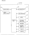
- FIG 1 is a block diagram showing a display device having a touch panel according to Embodiment 1 of the present invention.
- a PND 10 is provided with a storage unit 11, an external input unit 12, a speaker 13, an image display unit 17, a touch panel 18, a control unit 20, a GPS receiver 23, a gyro 25, a memory card slot 30 and a switch 31.
- GPS receiver 23, the gyro 25 and the speaker 13 need not be integrally provided in the PND 10 and may be configured to be electrically connectable to and detachable from the PND 10.
- the storage unit 11 is a data storage device such as an HDD, an SD card and a flash memory mounted on a printed circuit board in a PND in-vehicle device, and may adopt one kind or multiple kinds of them.
- the storage unit 11 stores data related to a shape of an icon displayed in the image display unit 17 or a basic program required to control operations of the PND, and, furthermore, stores various programs and databases such as a program to control the image display unit or an image display, application software used to perform a navigation function or a playback function of a moving image and music stored in a memory card inserted in a memory card slot, and a database related to a map for navigation or a telephone number database.
- the storage unit 11 is provided with an area for expanding various kinds of programs and data and an area for expanding an image.
- the external input unit 12 is an interface such as a connector provided to input a signal output from an external device connectable to the PND 10 and a level shifter for an input signal level, and can input video signals and sound signals acquired by reproducing media such as DVD and CD or video signals and sound signals from a digital television or the like.
- the speaker 13 is provided to output: sound effects to communicate to an operator that the PND 10 accepts an operation for the PND 10; sound input from an external device to the external input unit 12; and music or sound stored in a memory card inserted in the memory card slot 30.
- the image display unit 17 is provided to display on a screen: an opening screen or menu screen stored in the storage unit 11; a video or still image input from the external device to the external input unit 12; and various kinds of data such as moving images and still images stored in a memory card inserted in the memory card slot 30, and, in the present embodiment, a general liquid crystal display is used.
- the image display unit 17 is configured including: a liquid crystal panel including a polarization filter, a liquid crystal and a glass substrate; a component used as a light source for a cold cathode tube or a crystal panel such as an LED and a light guide board; an electronic component such as an IC to control various signals for image display; and a power supply unit to drive the liquid crystal, the light source and the electronic component.
- the power supply unit may be separately provided from the image display unit 17.
- the touch panel 18 is a transparent panel provided on a surface of the image display unit 17, and, when an operator operates a corresponding part (such as a position of an icon displayed on the image display unit in the case of icon display and an arbitrary place in the case of map display) of the touch panel 18 (i.e. when the operator touches or approaches to a corresponding part), the touch panel 18 outputs information of the operated position and information of capacitance variation caused by the operation to the control unit 20. By this means, an input operation to the PND 10 is performed.
- a corresponding part such as a position of an icon displayed on the image display unit in the case of icon display and an arbitrary place in the case of map display
- the control unit 20 includes a microprocessor and an electric circuit to operate the microprocessor, executes a control program stored in the storage unit 11 and performs various kinds of control processing. Further, the control unit 20 performs control processing so as to display image data, which is acquired as a result of control processing, on the display unit 17.
- control unit 20 acquires signals (i.e. information of the operated position and information of the capacitance variation caused by the operation) from the touch panel 18, calculates a position touched by the operator's finger on the touch panel based on these signals and checks information of the calculated position against information of a touch area of the touch panel 18 stored in the storage unit 11. After that, the control unit 20 executes a function defined by, for example, an icon, menu or switch associated in advance with a touch area corresponding to the position touched by the operator's finger.
- signals i.e. information of the operated position and information of the capacitance variation caused by the operation
- control unit 20 changes a touch detection threshold of the touch panel 18 by a signal from the switch 31.
- the touch detection threshold is a value compared with the capacitance variation detected in the touch panel 18 so as to determine whether the operator touches (i.e. operates) the touch panel 18.
- the number of microprocessors used for the control unit 20 may be one or a plurality of microprocessors may be used for a function of calculating a position touched by the operator's finger on the touch panel or a navigation function.
- the GPS receiver 23 is provided to receive a signal from a GPS satellite.
- the gyro 25 is provided to detect the rotation amount, variation in vertical directions or acceleration of the PND 10.
- the memory card slot 30 is provided to insert a memory card.
- the switch 31 is provided to detect that the operator performs an operation by one hand and is arranged in a position to which the operator's hand touches or approaches when the operator holds the PND 10.
- the switch 31 may be configured as, for example, a mechanic type of generating different signals according to whether the switch 31 is held down (or pressed), a type using a transmissive photo interrupter for generating different signals according to whether light is interrupted, or a type using a reflective photo sensor that detects whether the operator's hand is found by reflecting light to the operator's hand.
- Figure 2 is a simple configuration diagram for explaining usage patterns of the PND 10 according to Embodiment 1 of the present invention.
- the PND 10 serves dual purposes of a navigation device for pedestrians and an in-vehicle navigation device. That is, both cases are considered where the PND 10 is used by a user (or operator) while walking and where the PND 10 is taken to a vehicle, fixed to a predetermined place in the vehicle and used while the vehicle is moving.
- the PND 10 when the PND 10 is used by a user while walking, the user directly holds the PND 10 in a palm side of a hand and operates the PND 10.
- the touch panel 18 of the PND 10 is a capacitive touch panel, an operator's finger may cover the touch panel 18 when operating the PND 10, and, at that time, the capacitance value detected by the PND 10 slightly changes.
- the user when the user takes the PND 10 to a vehicle, normally, after the PND 10 is fixed to a dashboard or the like in the vehicle, the user operates or views the PND 10.
- the PND 10 is configured to separately recognize a state where the user directly holds the PND 10 in a palm side of a hand and uses the PND 10 (hereinafter an operation mode of the PND 10 in this state is referred to as "one-hand operation mode”) and a state where the user fixes (or simply places) the PND 10 to a specific position and uses the PND 10 (hereinafter an operation mode of the PND 10 in this state is referred to as "stationary operation mode").
- the switch 31 provided in the PND 10 is provided to identify the above two modes and switches signals between a state where the switch 31 is pressed (i.e. "ON” state) and a state where the switch 31 is not pressed (i.e. "OFF” state), and the control unit 20 recognizes this changeover, determines whether the current mode is the one-hand operation mode or the stationary operation mode, and performs control processing based on the determination result.
- the switch 31 is provided in an outer margin of the PND 10 in a state where the PND 10 is viewed from the front (i.e. anterior view) when using the PND 10 (see Figure 2 ), and, especially in the example shown in Figure 2 , the switch 31 is provided in the lower left in a state where the PND 10 is viewed from the front when the user operates the PND 10 by one hand (see Figure 2(b) ).
- the outer margin denotes an external margin of the device (i.e. PND 10) outside the display unit 17, including an outer part in the side or rear surface of the device.
- control unit 20 recognizes the one-hand operation mode in a period during which the switch 31 is pressed and the stationary operation mode in other periods (i.e. a period during which the switch 31 is not pressed).
- Figure 2(a) shows a configuration of the PND 10 alone according to Embodiment 1 and shows a state where the PND 10 has the image display unit 17 and the touch panel 18 is provided in front of the image display unit 17. Further, the figure shows that the switch 31 to detect a one-hand operation is provided on the PND 10.
- Figure 2(b) shows one example of the one-hand operation mode and is used for explaining that the PND 10 is held by one hand and operated by a finger of the holding hand. Further, Figure 2(b) shows that the operator holds the PND 10 by one hand so that it is possible to turn on the switch 31 of the PND 10 and touch and operate the touch panel 18 by a finger 71 of the holding hand.
- Figure 2(c) shows one example of the stationary operation mode and is a diagram for explaining a case where the PND 10 is installed and used in a vehicle interior or living space. Further, Figure 2(c) shows that, in a case where the PND 10 is attached to a stand 81, the operator can touch and operate the touch panel 18 of the PND 10 attached to the stand 81 by a finger 72.
- a capacitive touch panel detects a capacitance change caused by a finger approaching the touch panel and recognizes that the operator touches the touch panel when the capacitance change is equal to or greater than a touch detection threshold.
- the touch detection threshold denotes a value whereby the control unit recognizes that the operator operates the touch panel when a capacitance caused by a finger approaching the touch panel exceeds this touch detection threshold.
- this touch detection threshold by changing this touch detection threshold between the one-hand operation mode and the stationary operation mode, it is possible to prevent a false operation caused by covering the touch panel 18 with an operator's finger at the time of the one-hand operation mode.
- a touch detection threshold used for control in the stationary operation mode is TH1 and a touch detection threshold used for control in the one-hand operation mode is TH2.
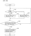
- step S1 The operations start from a state where nothing touches the touch panel 18 (corresponding to a start state in Figure 3 ).
- the control unit 20 determines an operation mode (step S1), that is, in a case where the PND 10 is attached to the stand 81, the control unit 20 detects that the switch 31 is turned off since the switch 31 is not pressed, and the control unit 20 determines that the PND 10 is not in the one-hand operation mode but in the stationary operation mode (step S1: NO).
- the control unit 20 sets a touch detection threshold to TH1 (step S3).
- step 4 determines this excess (step 4: YES), calculates a coordinate at which the operator touches the touch panel 18, and reads a function assigned to the coordinate from the storage unit 11 to execute the function (step S5).
- a capacitance detection value i.e. capacitance variation
- step S4 NO
- the flow returns to determination processing as to whether the operation mode is the one-hand operation mode (step S1).
- the operations start from a state where nothing touches the touch panel 18 (corresponding to a start state in Figure 3 ).
- the switch 31 is pressed and turned on and the control unit 20 detects a state of the switch 31 and determines that the PND 10 is in the one-hand operation mode (step S1: YES).
- control unit 20 determines that the operation mode is the one-hand operation mode, the control unit 20 sets the touch detection threshold to TH2.
- step S4 determines this (step S4: YES), calculates a coordinate at which the operator touches the touch panel 18, reads a function assigned to the coordinate from the storage unit 11 and executes the function (step S5).
- step S4 NO
- step S1 determines the one-hand operation mode as the operation mode and sets the touch detection threshold to TH2
- step S4: NO whether the operation mode is the one-hand operation mode is determined
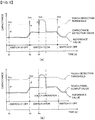
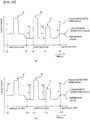
- the touch detection threshold TH1 at time t0 is set to a value obtained by adding a constant value ⁇ to a reference value in the control unit 20.
- the capacitance detection value slightly and gradually drifts by a usage environment change of the capacitive touch panel such as a temperature change and humidity change. Therefore, the control unit 20 sets the reference value in advance so as to change according to a gradual drift by a usage environment change of the capacitive touch panel.
- the drift occurrence time is set to t1 and the control unit 20 performs control so as to set the touch detection threshold TH1 at time t1 to a value obtained by adding the constant value ⁇ to the reference value and gradually change the touch detection value TH1 according to a change of the reference value at the time of drift occurrence.
- the time at which the operator touches the touch panel 18 is set to t2 and the time at which the operator lifts an operator's finger off the touch panel 18 is set to t3.
- the capacitance detection value largely changes in a short period of time compared to a drift change caused by an environment change.
- the control unit 20 does not change the reference value, the capacitance detection value exceeds the touch detection threshold TH1 and the control unit 20 determines this.
- control unit 20 determines that the capacitance detection value exceeds the touch detection threshold TH1, the control unit 20 does not change the reference value.
- the capacitance detection value largely changes in a short period of time compared to a drift change caused by an environment change and becomes smaller than the touch detection threshold.
- control unit 20 After the control unit 20 determines that the capacitance detection value becomes smaller than the touch detection value, the control unit 20 performs control again so as to change the touch detection threshold TH1 according to a change of the reference value.
- Figure 5(a) is a diagram showing a case where the touch detection threshold TH1 is constant and Figure 5(b) is a diagram showing a case where the touch detection threshold is changed to one of two values of the touch detection threshold TH1 and a touch detection threshold TH2.
- the PND 10 changes the touch detection threshold to one of the values TH1 and TH2 at the time of the one-hand operation mode, for ease of understanding, first, a harmful effect that can be caused in a case where the touch detection threshold is not changed but is fixed to TH1, will be explained using Figure 5(a) .
- the switch 31 when the operator holds the PND 10 by one hand and tries to operate the PND 10 by the finger 71 of the holding hand, the switch 31 is turned on, the capacitance detection value increases by the capacitance of the finger 71 of the holding hand and the control unit 20 changes the reference value according to the change of the capacitance detection value.
- the control unit 20 similarly changes the touch detection threshold TH1 adding ⁇ to the reference value.
- the PND 10 performs control while increasing the detection accuracy.
- the details are as follows.
- Figure 5(b) shows a case where the touch detection threshold is switched from the TH1 to TH2.
- the control unit 20 sets a value obtained by adding ⁇ , which is lower than ⁇ , to the reference value, as the touch detection value TH2.
- the capacitance detection value when the touch switch 31 is turned on, although the capacitance detection value increases according to an influence of the finger 71 of the hand holding the PND, this is caused by the operator's intended operation. Therefore, by switching touch detection thresholds between modes and setting a small difference between the reference value and the touch detection threshold, the capacitance detection value reliably exceeds the touch detection threshold, and therefore it is possible to perform a touch operation as intended by the operator.
- the present embodiment is provided with a capacitive touch panel, a switch for detecting a one-hand operation, a storage unit to store a touch detection threshold and a control unit to control the touch detection threshold, and, by changing the touch detection threshold according to an output of the switch that can detect the one-hand operation, the operator can operate the touch panel more reliably by the finger 71 of the hand holding a PND including a display device having the touch panel.
- an installation location of the switch 31 in the present embodiment may be the lower right side of the PND (i.e. the lower right side of the PND in the direction shown in Figure 2(b) ), and, in a case where the switch 31 is installed in the lower right, it is possible to hold the PND 10 by the right hand and operate the touch panel by a finger of the holding right hand.
- a plurality of the switches 31 may be provided and, in a case where the switches 31 are provided in the right and left parts, it is possible to operate the PND 10 by the right hand as well as the left hand as the operator likes.
- the PND 10 since it is generally expected to operate a portable device such as the PND 10 by one hand, although a one-hand operation has been exemplified and explained in the present embodiment, the PND 10 is not necessarily operated only by one hand, and it may be possible to press the switch 31 by one hand and perform an operation by the other hand.
- a display device having a conventional capacitive touch panel provides different sensor signal outputs in the vicinity of the touch panel between the case of holding the device by one hand and the case of holding the device by both hands, and therefore corresponding touch operations cannot be distinguished
- a display device according to this Embodiment 2 has a touch panel such that, even in a touch operation after an operator's finger stays near the touch panel before touching the touch panel, it is possible to increase the detection accuracy in a simple configuration and distinguish touch operations corresponding to the case of holding the device by one hand and the case of holding the device by both hands.
- Figure 6 is a block diagram of a display device having a touch panel according to Embodiment 2. It should be noted that, when the same members as in above Embodiment 1 are used in the following explanation, the same reference numerals will be assigned to the members and their explanation will be omitted.
- a PND 40 is provided with the storage unit 11, the external input unit 12, the speaker 13, the image display unit 17, the touch panel 18, the control unit 20, the GPS receiver 23, the gyro 25, the memory card slot 30, a switch 41a as a first switch and a switch 41b as a second switch.
- the switches 41a and 41b are provided to detect whether the operator holds (or holds and operates) the PND 40 by one hand or the operator holds (or holds and operates) the PND 40 by both hands, and are arranged in positions to which the operator's hand touches or approaches when the operator holds the PND 40.
- the switches 41a and 41b may be configured as, for example, a mechanic type of generating different signals according to whether the switches 41a and 41b are held down (or pressed), a type using a transmissive photo interrupter for generating different signals according to whether light is interrupted, or a type using a reflective photo sensor that detects whether the operator's hand is found by reflecting light to the operator's hand.
- the control unit 20 changes a touch detection threshold of the touch panel 18 by signals from the switches 41a and 41b.
- Figure 7 is a simple configuration diagram for explaining usage patterns of the PND 40 according to Embodiment 2 of the present invention.
- the PND 40 serves dual purposes of a navigation device for pedestrians and an in-vehicle navigation device. That is, both cases are considered where the PND 40 is used by a user (or operator) while walking and where the PND 40 is taken to a vehicle, fixed to a predetermined place in the vehicle and used while the vehicle is moving.
- the PND 40 when the PND 40 is used by the user while walking, the user directly holds the PND 10 in a palm side of a hand and operates the PND 40.
- the touch panel 18 of the PND 40 is a capacitive touch panel
- an operator's finger may cover the touch panel 18 when operating the PND 40, and, at that time, the capacitance value detected by the PND 40 slightly changes.
- the capacitance value variation is different between these cases.
- the user takes the PND 40 to a vehicle
- the PND 40 is fixed to a dashboard or the like in the vehicle
- the user operates or views the PND 40.
- the PND 40 is fixed to a specific position such as a dashboard, except for when the operator intentionally operates the PND 40, a situation does not arise in operations of the PND 40 where an operator's finger covers the PND 40.
- the PND 40 is configured to separately recognize: a state where the user directly holds the PND 40 in a palm side of a hand and uses the PND 40 (hereinafter an operation mode of the PND 40 in this state is referred to as "one-hand operation mode”); a state where the user directly holds the PND 40 in a palm side of hands and uses the PND 40 (hereinafter an operation mode of the PND 40 in this state is referred to as “both-hands operation mode”); and a state where the user fixes (or simply places) the PND 40 to a specific position and uses the PND 40 (hereinafter an operation mode of the PND 40 in this state is referred to as "stationary operation mode").
- the switch 41 (i.e. 41a and 41b) provided in the PND 40 is provided to identify the above two modes and switches signals between a state where the switch 41 is pressed (i.e. "ON” state) and a state where the switch 41 is not pressed (i.e. "OFF” state), and the control unit 20 recognizes this changeover, determines in which of the one-hand operation mode, the both-hands operation mode and the stationary operation mode the current mode is, and performs control processing based on the determination result.
- the switch 41 is provided in an outer margin of the PND 40 in a state where the PND 40 is viewed from the front (i.e. anterior view) when using the PND 40 (see Figure 7 ), and, especially in the example shown in Figure 7 , the switches 41a and 41b are provided in the lower left and the lower right, respectively, in a state where the PND 40 is viewed from the front when the user operates the PND 40 by one hand (see Figure 7(b) ) .
- the outer margin denotes an external margin of the device (i.e. PND 40) outside the display unit 17, including an outer part in the side or rear surface of the device.
- control unit 20 recognizes the one-hand operation mode in a period during which the switch 41a or 41b is pressed, the both-hands operation mode in a period during which the switches 41a and 41b are both pressed, and the stationary operation mode in other periods (i.e. a period during which the switch 41 is not pressed).
- Figure 7(a) shows a configuration of the PND 40 alone according to Embodiment 1 and shows a state where the PND 40 has the image display unit 17 and the touch panel 18 is provided in front of the image display unit 17. Further, the figure shows that the switch 41 to detect a one-hand operation is provided on the PND 40.
- Figure 7(b) shows one example of the one-hand operation mode and is used for explaining that the PND 40 is held by one hand and operated by a finger of the holding hand. Further, Figure 7(b) shows that the operator holds the PND 40 by one hand so that it is possible to turn on the switch 41a (or 41b) of the PND 40 and touch and operate the touch panel 18 by the finger 71 of the holding hand.
- Figure 7(c) shows one example of the both-hands operation mode and is used for explaining that the PND 40 is held by both hands and operated by fingers of the holding hands. Further, Figure 7(c) shows that the operator holds the PND 40 by both hands so that it is possible to turn on the switches 41a and 41b of the PND 40 and touch and operate the touch panel 18 by a finger 71a or 71b of the holding hands.
- Figure 7(d) shows one example of the stationary operation mode and is a diagram for explaining a case where the PND 40 is installed and used in a vehicle interior or living space. Further, Figure 7(d) shows that, in a case where the PND 40 is attached to the stand 81, the operator can touch and operate the touch panel 18 of the PND 40 attached to the stand 81 by the finger 72.
- a capacitive touch panel detects a capacitance change caused by a finger approaching the touch panel and recognizes that the operator touches the touch panel when the capacitance change is equal to or greater than a touch detection threshold.
- the touch detection threshold denotes a value whereby the control unit recognizes that the operator operates the touch panel when a capacitance caused by a finger approaching the touch panel exceeds this touch detection threshold.
- this touch detection threshold by changing this touch detection threshold between the one-hand operation mode, the both-hands operation mode and the stationary operation mode, it is possible to prevent a false operation caused by covering the touch panel 18 with an operator's finger at the time of each operation mode.
- a touch detection threshold used for control in the stationary operation mode is TH1
- a touch detection threshold used for control in the one-hand operation mode is TH2
- a touch detection threshold used for control in the both-hands operation mode is TH3.
- the operations start from a state where nothing touches the touch panel 18 (corresponding to a start state in Figure 8 ).
- the control unit 20 determines an operation mode.
- control unit 20 detects states of the switches 41a and 41b and determines whether the operator performs an operation (or holds the PND) by both hands (step S11).
- step S11 when it is determined that both the switches 41a and 41b are pressed (i.e. the switches 41 are turned on), this shows a state where the user operates (or holds) the PND by both hands (step S11: YES), and the flow proceeds to the next processing.
- the control unit 20 sets the touch detection threshold to TH3 (step S12) and determines an operation mode of the PND as the both-hands operation mode.
- step S11 when it is determined that one of the switches 41a and 41b is not pressed (i.e. one of the switches 41 is turned off), this shows a state where the user does not operate (or hold) the PND by both hands (step S11: NO), and the flow proceeds to the next processing.
- step S11 the control unit 20 determines whether the operator performs an operation (or holds the PND) by one hand (step S13).
- step S13 when it is determined that only one of the switches 41a and 41b is pressed (i.e. only one of the switches 41 is turned on), this shows a state where the user operates (or holds) the PND by one hand (step S13: YES), and the flow proceeds to the next processing.
- the control unit 20 sets the touch detection threshold to TH2 (step S14) and determines an operation mode of the PND as the one-hand operation mode.
- step S13 when it is determined that none of the switches 41a and 41b is pressed, since this shows a state where the user does not operate (or hold) the PND by one hand or both hands (step S13: NO), the control unit 20 sets the touch detection threshold to the normal value TH1 (step S15) and determines an operation mode of the PND as the stationary operation mode.
- a capacitance of the touch panel 18 is detected in the state and it is determined whether the detected capacitance value exceeds the touch detection threshold set in each step (step S16).
- the control unit 20 determines this excess, calculates a coordinate at which the operator touches the touch panel 18, and reads a function assigned to the coordinate from the storage unit 11 to execute the function (step S17).
- step S16 NO
- the flow returns to determination processing as to whether the operation mode is the both-hands operation mode (step S11).
- Figure 9(a) is a diagram showing a state where the touch detection threshold is constant (TH1 in this case)
- Figure 9(b) is a diagram showing a case where the touch detection threshold is changed to one of two values of the touch detection threshold TH1 and a touch detection threshold TH 2.
- Figure 9(c) is a diagram showing a case where the touch detection threshold is changed to one of the touch detection threshold TH1, the touch detection threshold TH2 and a touch detection threshold T3.
- the PND 40 sets the touch detection threshold to one of TH1, TH2 and TH3 in a switched manner for each operation mode.
- Figure 9(a) shows that, when the operator holds the PND 40 by one hand in a case where the touch detection threshold is not changed and is fixed to TH1, the operation becomes invalid even if the operator touches the touch panel 18, since the touch detection value does not exceed the touch detection threshold (TH1). This is the same as described in Embodiment 1 ( Figure 5(a) ) and therefore explanation will be omitted.
- a trouble that an operation becomes invalid because the touch detection value does not exceed the touch detection threshold (TH1) occurs not only in a case where the operator holds the PND by one hand but also in a case where the operator holds the PND by both hands. Further, even if the touch detection thresholds are set to a constant value (e.g. TH2) in both of the case of holding and using the PND by one hand and the case of holding and using the PND by both hands, the same trouble may occur.
- the PND 40 performs control while increasing the detection accuracy.
- the details are as follows. First, a case will be explained using Figure 9(b) where the touch detection value is changed from TH1 to TH2.
- the control unit 20 sets a value obtained by adding ⁇ , which is lower than ⁇ , to the reference value, as the touch detection value TH2.
- a touch panel output value gradually increases. After that, when the operator holds the PND by one hand and tries to operate the PND by the finger 71 of the holding hand, the capacitance detection value increases by the capacitance of the finger 71a of the holding hand.
- control unit 20 changes the reference value according to the change of the capacitance detection value. After that, at time “th" the switch 41a (or 41b) of the PND 40 is pressed by the operator and therefore the switch 41a (or 41b) is turned on.
- control unit 20 continues the processing flow shown in Figure 8 and therefore sets a value obtained by adding ⁇ , which is lower than ⁇ , to the reference value, as the touch detection value TH2.
- Figure 9(c) supplementary shows waveforms in a case where the operator performs a touch operation in a state before changing the touch detection value to TH3 after changing the touch detection value from TH1 to TH2. However, in this state, the operator needs not necessarily perform the touch operation.
- the capacitance detection value increases by the capacitance of the finger 71a of the holding hands.
- the control unit 20 changes the reference value according to the change of the capacitance detection value. After that, at time “tk” the switch 41b (or switch 41a) of the PND 10 is pressed by the operator and therefore the switch 41b (or switch 41a) is turned on. At this time, as described above, the control unit 20 continues the processing flow shown in Figure 8 and therefore sets a value obtained by adding ⁇ , which is lower than ⁇ , to the reference value, as the touch detection value TH3.
- the capacitance detection value when the switch 41 is turned on, although the capacitance detection value increases according to an influence of the finger 71 of the hand holding the PND, this is caused by the operator's intended operation. Therefore, by switching touch detection thresholds between modes and setting a small difference between the reference value and the touch detection threshold, the capacitance detection value reliably exceeds the touch detection threshold, and therefore it is possible to perform a touch operation as intended by the operator.
- the present embodiment is provided with a capacitive touch panel, a switch for detecting a one-hand operation, a storage unit to store a touch detection threshold and a control unit to control the touch detection threshold, and, by changing the touch detection threshold according to an output of the switch that can detect the one-hand operation, the operator can operate the touch panel more reliably by the finger 71 of the hand holding a PND including a display device having the touch panel.
- a display device having a conventional capacitive touch panel provides different sensor signal outputs in the vicinity of the touch panel between the case of holding the device by one hand and the case of holding the device by both hands, and therefore corresponding touch operations cannot be distinguished.
- two switches 41a and 41b in the outer margin of the display device it is possible to reliably determine whether the operator holds the display device by one hand, and, by changing the touch detection threshold according to this determination result, it is possible to reliably distinguish between the case of holding the device by one hand and the case of holding the device by both hands.
- the display device has a large size
- a person of muscle holds and operates the device by one hand while a powerless person holds and operates the device by both hands, that is, it is possible to use the device according to user preferences.
- Embodiment 3 of the present invention will be explained.
- a display device according to the present embodiment has a touch panel such that, even in a touch operation after an operator's finger stays near the touch panel before touching the touch panel, it is possible to increase the detection accuracy in a simple configuration and improve the operability especially when holding and operating a small or portable display device by one hand.
- FIG 10 is a block diagram of a display device having a touch panel according to Embodiment 3 of the present invention.
- a PND 50 is provided with a storage unit 51, the external input unit 12, the speaker 13, the image display unit 17, the touch panel 18, the control unit 20, the GPS receiver 23, the gyro 25, the memory card slot 30 and the switch 31.
- the storage unit 51 is a data storage device such as an HDD, an SD card and a flash memory mounted on a printed circuit board in a PND in-vehicle device, and may adopt one kind or multiple kinds of them.
- the storage unit 51 stores data related to a shape of an icon displayed in the image display unit 17 or a basic program required to control operations of the PND, and, furthermore, stores various programs and databases such as a program to control the image display unit or an image display, application software used to perform a navigation function or a playback function of a moving image and music stored in a memory card inserted in the memory card slot 30, and a database related to a map for navigation or a telephone number database.
- the storage unit 51 is provided with an area for expanding various kinds of programs and data and an area for expanding an image.
- the storage unit 51 stores icon layouts corresponding to a plurality of operation modes which will be described later in detail.
- the icon layout denotes an arrangement pattern in which icons for an input operation by an operator are arranged to execute each function of the PND 50 such as a periphery search and a point registration.
- the PND 50 according to Embodiment 3 is configured to separately recognize a state where the user directly holds the PND 50 in a palm side of a hand and uses the PND 50 (i.e. one-hand operation mode) and a state where the user fixes (or simply places) the PND 10 to a specific position and uses the PND (i.e. stationary operation mode), according to whether the switch 31 is pressed. It should be noted that usage patterns of the PND 50 are the same as explained in Embodiment 1 (see Figure 2 ) and therefore specific explanation will be omitted.
- display layouts of operation icons to improve the operability especially at the time of the one-hand operation mode are common in that operation icons are arranged in positions near the switch 31 on the image display unit (i.e. within a range in which the operator's finger 71 is touchable) such that the operator handily operates (e.g. touch operation or input operation) the PND 50 by the finger 71 (especially, indicating a thumb in the present embodiment) of the hand holding the PND 50 while maintaining a state where the operator holds the PND 50 by one hand and the switch 31 is turned on.
- operation icons are arranged in positions near the switch 31 on the image display unit (i.e. within a range in which the operator's finger 71 is touchable) such that the operator handily operates (e.g. touch operation or input operation) the PND 50 by the finger 71 (especially, indicating a thumb in the present embodiment) of the hand holding the PND 50 while maintaining a state where the operator holds the PND 50 by one hand and the switch 31 is turned on.
- Figure 11 is a diagram showing a display layout (or one-hand operation layout) example of operation icons at the time of the one-hand operation mode of the PND 50 according to the present embodiment.
- a display layout shown in Figure 11(a) denotes a layout in which operation icons A to C are linearly arranged in tandem in the lower left of the image display unit 17 of the PND 50 in a state where the operator holds the PND 50 vertically and the switch 31 is turned on by a palm of the operator's left hand.
- a display layout shown in Figure 11(b) denotes a layout in which operation icons D to F are arranged in parallel in addition to the layout in which the operation icons A to C are linearly arranged in tandem in the lower left of the image display unit 17 of the PND 50 (i.e. the display layout as Example 1), in a state where the operator holds the PND 50 vertically and the switch 31 is turned on by the palm of the operator's left hand.
- a display layout shown in Figure 11(c) denotes a layout in which operation icons G to J are arranged in an arc-like manner on the lower left side in the image display unit 17 of the PND 50, in a state where the operator holds the PND 50 vertically and the switch 31 is turned on by the palm of the operator's left hand.
- This arc i.e. the ark shown by dash line in Figure 11(c)
- dash line is added for the purpose of explanation and is not actually displayed in the image display unit 17.
- the motion of the finger 71 is limited when moving the finger 71 for operation, and, taking into account that the finger 71 is naturally moved in a state where the switch 31 is turned on, it is generally considered that the trajectory described by this fingertip becomes arc-like, so that it is possible to move the operator's finger 71 smoothly at the time of operation.
- the above arc is not limited to an arc as part of a true circle, and, taking into account further improvement of the operability by the operator, it may be possible to arrange operation icons K to N on an arc that is part of an ellipse as shown in Figure 11(d) as Example 4.
- the number of operation icons is not limited to the above number and may be one or two. Furthermore, within a range in which the operator's finger is touchable, it is possible to arrange operation icons corresponding to the number equal to or greater than the above exemplified numbers.
- operation icons arranged near the switch 31 are determined by a manufacturer of the PND 50 or selected by the user of the PND 50 with due consideration of features of the one-hand operation mode, an operation icon of less use frequency is arranged in a position apart from the operator's finger 71.
- an operation icon to search surrounding facilities of the operator is given.
- this operation icon it is possible to search surrounding facilities of the operator who operates the PND in the one-hand mode, and therefore the operation icon is useful to search surrounding stations, restaurants or the like.
- the control unit 20 calls icons related to stations, restaurants or the like in the storage unit 51 and displays these icons on the image display unit 17. By touching the touch panel 18, the operator can search an intended facility.
- a neighboring station icon or neighboring toilet icon to search a station or toilet of high use frequency at one touch of the button may be arranged near the switch 31.
- an operation icon for point registration is given. This operation icon is provided to register a curious place while walking, and, when this operation icon is operated, information (e.g. latitude and longitude) showing the place is registered (or stored) in the PND 50.
- an operation icon to register a note is given. This operation icon is provided to record what is curious while walking, and, when this operation icon is operated, the location is registered and the operator can record a note.
- a capacitive touch panel detects a capacitance change caused by a finger approaching the touch panel and recognizes that the operator touches the touch panel when the capacitance change is equal to or greater than a touch detection threshold.
- the touch detection threshold denotes a value whereby the control unit recognizes that the operator operates the touch panel when a capacitance caused by a finger approaching the touch panel exceeds this touch detection threshold.
- this touch detection threshold by changing this touch detection threshold between the one-hand operation mode and the stationary operation mode, it is possible to prevent a false operation caused by covering the touch panel 18 with an operator's finger at the time of the one-hand operation mode.
- a touch detection threshold used for control in the stationary operation mode is TH1 and a touch detection threshold used for control in the one-hand operation mode is TH2.
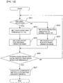
- the operations start from a state where nothing touches the touch panel 18 (corresponding to a start state in Figure 12 ).
- the control unit 20 determines an operation mode (step S21), that is, in a case where the PND 50 is attached to the stand 81, the control unit 20 detects that the switch 31 is turned off since the switch 31 is not pressed, and the control unit 20 determines that the PND 50 is not in the one-hand operation mode but in the stationary operation mode (step S21: NO).
- the control unit 20 sets a touch detection threshold to TH1 (step S22).
- control unit 20 calls an icon layout corresponding to the stationary operation mode from the storage unit 51 and sets the icon layout to be displayed on the image display unit 17 (step S23).
- the icon layout corresponding to the stationary operation mode may denote a general icon layout and specific explanation will be omitted.
- step S23 when the operator touches the touch panel 18 and a capacitance detection value (i.e. capacitance variation) exceeds the touch detection threshold (or TH1 in this case), the control unit 20 determines this excess (step 26: YES), calculates a coordinate at which the operator touches the touch panel 18, and reads a function assigned to the coordinate from the storage unit 51 to execute the function (step S27).
- a capacitance detection value i.e. capacitance variation
- step S26 NO
- the flow returns to determination processing as to whether the operation mode is the one-hand operation mode (step S21).
- the operations start from a state where nothing touches the touch panel 18 (corresponding to a start state in Figure 12 ).
- the switch 31 is pressed and turned on and the control unit 20 detects a state of the switch 31 and determines that the PND 10 is in the one-hand operation mode (step S21: YES).
- control unit 20 determines that the operation mode is the one-hand operation mode, the control unit 20 sets the touch detection threshold to TH2 (step S24).
- control unit 20 calls an icon layout corresponding to the one-hand operation mode from the storage unit 51 and sets the icon layout to be displayed on the image display unit 17 (step S25).
- the icon layout corresponding to the one-hand operation mode denotes an icon layout in which main operation icons are arranged near the switch 31, and specific explanation will be omitted.
- step S26 determines this (step S26: YES), calculates a coordinate at which the operator touches the touch panel 18, reads a function assigned to the coordinate from the storage unit 51 and executes the function (step S27).
- control unit 20 determines the one-hand operation mode as the operation mode and sets the touch detection threshold to TH2, when the capacitance detection value does not exceed the touch detection threshold (or TH2 in this case) (step S26: NO), whether the operation mode is the one-hand operation mode is determined (step S21).
- an installation location of the switch 31 in the present embodiment may be the lower right side of the PND, and, in a case where the switch 31 is installed in the lower right, it is possible to hold the PND 50 by the right hand and operate the touch panel by a finger of the holding right hand.
- a plurality of the switches 31 may be provided and, in a case where the switches 31 are provided in the right and left parts, it is possible to operate the PND 50 by the right hand as well as the left hand as the operator likes.
- the PND 50 since it is generally expected to operate a portable device such as the PND 50 by one hand, although a one-hand operation has been exemplified and explained in the present embodiment, the PND 50 is not necessarily operated only by one hand, and it may be possible to press the switch 31 by one hand and perform an operation by the other hand.
- Embodiment 4 of the present invention will be explained.
- a display device having a touch panel when a display device having a touch panel is applied to an in-vehicle device, since operation devices with respect to other in-vehicle devices than this display device concentrate around the driving seat or dashboard, the user's hand or arm often crosses near the display device having the touch panel, and therefore it is concerned that a capacitance near the touch panel changes significantly and many false operations of the display device are caused.
- a display device according to the present embodiment has a touch panel such that, even in a touch operation after an operator's finger stays near the touch panel before touching the touch panel, it is possible to increase the detection accuracy in a simple configuration and reduce a false operation especially when the display device is applied to an in-vehicle device.
- FIG 13 is a block diagram of a display device having a touch panel according to Embodiment 3 of the present invention.
- a PND 60 is provided with the storage unit 11, the external input unit 12, the speaker 13, the image display unit 17, the touch panel 18, the control unit 20, the GPS receiver 23, the gyro 25, the memory card slot 30 and a switch 61.
- the switch 61 is turned on when the PND 60 is attached to the stand 82 to fix the PND 60 in a specific position in a case where the PND 60 is used as a so-called in-vehicle device (e.g. in a case where the PND 60 is used in a car).
- the switch 61 may be configured as, for example, a mechanic type of generating different signals according to whether the switch 61 is held down (or pressed), a type using a transmissive photo interrupter for generating different signals according to whether light is interrupted, or a type using a reflective photo sensor to detect that the PND 60 is attached to the stand 82 by reflecting light to the stand 82.
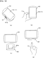
- Figure 14 is a simple configuration diagram for explaining usage patterns of the PND 60 according to Embodiment 4 of the present invention.
- the PND 60 serves dual purposes of a navigation device for pedestrians and an in-vehicle navigation device.
- both cases are considered where the PND 60 is used by a user (or operator) while walking and where the PND 60 is taken to a vehicle, fixed to a predetermined place in the vehicle and used while the vehicle is moving.
- Figure 14(b) is a diagram showing an example case where the PND is used by the user (or operator) while walking. As shown in Figure 14(b) , the PND 60 is small to the extent that it is possible to hold and operate the PND 60 by one hand.
- Figure 14(c) and Figure 14(d) are diagrams showing an example case where the PND is used as an in-vehicle PND, and Figure 14(c) shows a state before the PND 60 is attached to the stand 82 to fix the PND 60 in an intended position in the vehicle, and Figure 14(d) shows a state where the PND 10 is moved down from the state shown in Figure 14(c) and fixed to the stand 82.
- the PND 60 when the PND 60 is used by a user while walking, the user directly holds the PND 60 in a palm side of a hand and operates the PND 60.
- the touch panel 18 of the PND 60 is a capacitive touch panel, an operator's finger may cover the touch panel 18 when operating the PND 60, and, at that time, the capacitance value detected by the PND 60 slightly changes.
- the user when the user takes the PND 60 to a vehicle, normally, after the PND 60 is fixed to a dashboard or the like in the vehicle, the user operates or views the PND 60.
- the PND 60 is operated limitedly in a specific position such as a dashboard, operation devices to operate other devices provided in advance such as an air conditioner, a blinker and a head light are installed in the vehicle, where most of these operation devices are arranged in operable positions from the driving seat.
- operation devices to operate other devices provided in advance such as an air conditioner, a blinker and a head light are installed in the vehicle, where most of these operation devices are arranged in operable positions from the driving seat.
- the PND 60 is arranged in an operable position from the driving seat in many cases, even in other cases than a case where the operator intentionally operates the PND 60, a state often occurs where an operator's arm or finger may cross or cover the vicinity of the PND 60 (specifically, the touch panel 18).
- the PND 60 is configured to separately recognize a state where the user directly holds the PND 60 in a palm side of a hand and uses the PND 60 (hereinafter an operation mode of the PND 60 in this state is referred to as "one-hand operation mode”) and a state where the user fixes (or simply places) the PND 60 to a specific position and uses the PND 60 (hereinafter an operation mode of the PND 60 in this state is referred to as "stationary operation mode").
- the switch 61 provided in the PND 60 is provided to identify the above two modes and switches signals between a state where the switch 61 is pressed (i.e. "ON” state) and a state where the switch 61 is not pressed (i.e. "OFF” state), and the control unit 20 recognizes this changeover, determines whether the current mode is the one-hand operation mode or the stationary operation mode, and performs control processing based on the determination result.
- the switch 61 is provided such that the switch 61 is switched to the "ON" state only when the PND 60 is attached to the stand 82 fixed in the vehicle.
- a concavity portion 61a hollowed to the main body side of the PND 60 is provided in an outer margin of the PND 60 in a state where the PND 60 is viewed from the front (i.e. anterior view), and the switch 61 is provided in the center part of the concavity portion 61a.
- the outer margin denotes an external margin of the device (i.e. PND 60) outside the display unit 17, including an outer part in the side or rear surface of the device.
- the stand 82 is provided with a convexity portion 82a fitting the concavity portion 61a in a state where the PND 60 is attached to the stand 82. That is, by inserting the convexity portion 82a of the stand 82 in the concavity portion 32a of the PND 60, the convexity portion 82a presses the switch 61.
- the concavity portion 61a and the convexity portion 82a are fitted so that it is possible to stabilize relative positions of the PND 60 and the stand 82.
- control unit 20 recognizes the one-hand operation mode in a period during which the switch 61 is not pressed and the stationary operation mode in other periods (i.e. a period during which the switch 61 is pressed).
- Figure 14(a) shows a configuration of the PND 60 alone according to Embodiment 4 and shows a state where the PND 60 has the image display unit 17 and the touch panel 18 is provided in front of the image display unit 17. Further, the figure shows that the switch 61 to detect the PND 60 fixed into a vehicle is provided on the PND 60.
- Figure 14(b) shows one example of the one-hand operation mode and is used for explaining that the PND 60 is held by one hand and operated by a finger of the holding hand. Further, Figure 14(b) shows that the operator holds the PND 60 by one hand so that it is possible to operate the touch panel 18 by the finger 71 of the holding hand.
- the operator may operate the PND 60 by both hands at the time of this one-hand operation mode.
- Figure 14(c) and Figure 14(d) show one example of the stationary operation mode and are diagrams for explaining a case where the PND 60 is installed and used in a vehicle. Further, these figures show that, in a case where the PND 60 is attached to a stand 82, the operator can touch and operate the touch panel 18 of the PND 60 attached to the stand 82 by the finger 72.
- a capacitive touch panel detects a capacitance change caused by a finger approaching the touch panel and recognizes that the operator touches the touch panel when the capacitance change is equal to or greater than a touch detection threshold.
- the touch detection threshold denotes a value whereby the control unit recognizes that the operator operates the touch panel when a capacitance caused by a finger approaching the touch panel exceeds this touch detection threshold.
- this touch detection threshold by changing this touch detection threshold between the one-hand operation mode and the stationary operation mode, it is possible to prevent a false operation caused by covering the touch panel 18 with an operator's finger at the time of the one-hand operation mode.
- a touch detection threshold used for control in the one-hand operation mode is TH1 and a touch detection threshold used for control in the stationary operation mode is TH2.
- the operations start from a state where nothing touches the touch panel 18 (corresponding to a start state in Figure 15 ).
- the control unit 20 determines an operation mode (step S31). That is, in a case where the PND 60 is not attached to the stand 82, the control unit 20 detects that the switch 61 is turned off since the switch 61 is not pressed, and the control unit 20 determines that the PND 60 is not in the stationary operation mode but in the one-hand operation mode (step S31: NO).
- the control unit 20 sets a touch detection threshold to TH1 (step S33).
- step 34 determines this excess (step 34: YES), calculates a coordinate at which the operator touches the touch panel 18, and reads a function assigned to the coordinate from the storage unit 11 to execute the function (step S35).
- a capacitance detection value i.e. capacitance variation
- step S34 NO
- the flow returns to determination processing as to whether the operation mode is the one-hand operation mode (step S31).
- the operations start from a state where nothing touches the touch panel 18 (corresponding to a start state in Figure 15 ).
- the switch 61 is pressed and turned on and the control unit 20 detects a state of the switch 61 and determines that the PND 60 is in the stationary operation mode (step S31: YES) .
- control unit 20 determines that the operation mode is the stationary operation mode, the control unit 20 sets the touch detection threshold to TH2 (step S32).
- step S34 determines this (step S34: YES), calculates a coordinate at which the operator touches the touch panel 18, reads a function assigned to the coordinate from the storage unit 11 and executes the function (step S35).
- step S34 NO
- whether the operation mode is the one-hand operation mode is determined (step S31).
- Figure 16(a) is a diagram showing a state where the touch detection threshold TH1 is constant
- Figure 16(b) is a diagram showing a case where the touch detection threshold is changed to one of two values of the touch detection threshold TH1 and the touch detection threshold TH2.
- the PND 60 changes the touch detection threshold to one of the values TH1 and TH2 at the time of the one-hand operation mode, for ease of understanding, first, a harmful effect that can be caused in a case where the touch detection threshold is not changed but is fixed to TH1, will be explained using Figure 16(a) .
- the control unit 20 changes the reference value according to the capacitance detection value change.
- the control unit 20 similarly changes the touch detection threshold TH1 adding ⁇ to the reference value.
- the capacitance detection value can exceed the touch detection threshold TH1, which results in executing a function set in a position corresponding to the coordinate at which this capacitance is detected.
- touch detection threshold TH1 adding ⁇ to the reference value in a simple manner is set as a touch detection threshold without taking into account the increment, even if the operator does not touch the touch panel 18, the touch detection value exceeds the touch detection threshold (or the touch detection threshold TH1 in this case) when a finger or arm of the operator temporarily approaches the touch panel 18, and therefore the operation becomes valid.
- the PND 60 performs control while increasing the detection accuracy.
- the details are as follows.
- the present embodiment is provided with a capacitive touch panel, a switch for detecting a stand attachment, a storage unit to store a touch detection threshold and a control unit to control the touch detection threshold, and, by changing the touch detection threshold according to an output of the switch that can detect the stand attachment, it is possible to reduce a false operation even in a case where a PND including a display device having the touch panel is mounted on a vehicle and tried out by the operator.
- a display device having a touch panel relates to a display device having a touch panel that performs a predetermined input by operator's touch operation in front of an image display unit that displays predetermined content, and is useful as a display device having a touch panel applied to mobile devices such as a PND and portable multimedia player that are often operated while walking.
Claims (12)
- Dispositif d'affichage ayant un panneau tactile capacitif (18) devant une unité d'affichage d'image (17), le panneau tactile (18) détectant un changement de capacité, le dispositif d'affichage comprenant :une unité de commande (20) qui définit un seuil à comparer à une variation d'une capacité détectée par le panneau tactile (18) pour déterminer si le panneau tactile (18) fonctionne ; etun commutateur (31, 41, 61) qui amène l'unité de commande (20) à détecter que le dispositif d'affichage est tenu par un opérateur,dans lequel l'unité de commande (20) règle le seuil à une valeur différente en fonction d'un résultat de détection en utilisant le commutateur (31, 41, 61), etdans lequel l'unité de commande (20) règle un seuil pour le cas où il est détecté par le commutateur (31, 41, 61) que l'opérateur tient le dispositif d'affichage à une valeur inférieure à un seuil pour le cas où il n'est pas détecté que l'opérateur tient le dispositif d'affichage.
- Dispositif d'affichage selon la revendication 1, dans lequel le commutateur (31, 41, 61) est prévu dans une marge du dispositif d'affichage et dans un côté inférieur gauche de l'unité d'affichage d'image (17) dans une vue de face.
- Dispositif d'affichage selon la revendication 1, dans lequel le commutateur (31, 41, 61) est prévu dans une marge du dispositif d'affichage et dans un côté inférieur droit de l'unité d'affichage d'image (17) dans une vue de face.
- Dispositif d'affichage selon la revendication 1, dans lequel le commutateur (31, 41, 61) est prévu dans une marge du dispositif d'affichage et à droite et à gauche en dessous de l'unité d'affichage d'image (17) dans une vue de face.
- Dispositif d'affichage selon l'une quelconque des revendications 1 à 4, dans lequel :le commutateur comprend un premier commutateur (41a) et un deuxième commutateur (41b) ;l'unité de commande (20) règle le seuil à un premier seuil lorsqu'il est détecté que le premier commutateur (41a) et le deuxième commutateur (41b) sont désactivés, règle le seuil à un deuxième seuil lorsqu'il est détecté que seul le premier commutateur (41a) est activé et règle le seuil à un troisième seuil lorsqu'il est détecté que le premier commutateur (41a) et le deuxième commutateur (41b) sont tous deux activés ; etle troisième seuil est une valeur inférieure au deuxième seuil et le deuxième seuil est une valeur inférieure au premier seuil.
- Dispositif d'affichage selon la revendication 5, dans lequel le premier commutateur (41a) est prévu dans une marge du dispositif d'affichage et dans l'un d'un côté inférieur droit et d'un côté inférieur gauche de l'unité d'affichage d'image (17) dans une vue de face, et le deuxième commutateur (41b) est prévu dans l'autre côté de l'unité d'affichage d'image (17).
- Dispositif d'affichage selon l'une quelconque des revendications 1 à 4, comprenant en outre une unité de stockage (11, 51) qui stocke plusieurs types de dispositions d'icônes,
dans lequel l'unité de commande (20) règle le seuil à une valeur différente en fonction du résultat de détection en utilisant le commutateur (31, 41, 61) et affiche la disposition d'icônes correspondant au résultat de détection en utilisant le commutateur (31, 41, 61) sur l'unité d'affichage d'image (17). - Dispositif d'affichage selon la revendication 7, dans lequel l'unité de commande (20) affiche une disposition de fonctionnement à une seule main sur l'unité d'affichage d'image (17) lorsqu'il est détecté que l'opérateur tient le dispositif d'affichage, la disposition de fonctionnement à une seule main étant une disposition d'icônes dans laquelle des icônes de fonctionnement sont agencées à proximité du commutateur (31, 41, 61).
- Dispositif d'affichage selon la revendication 8, dans lequel les icônes de fonctionnement sont agencées en ligne dans la disposition de fonctionnement à une seule main.
- Dispositif d'affichage selon la revendication 8, dans lequel les icônes de fonctionnement sont agencées en une pluralité de lignes dans la disposition de fonctionnement à une seule main.
- Dispositif d'affichage selon la revendication 8, dans lequel les icônes de fonctionnement sont agencées en forme d'arc dans la disposition de fonctionnement à une seule main.
- Dispositif d'affichage ayant un panneau tactile capacitif (18) qui détecte un changement de capacité, devant une unité d'affichage d'image (17), le dispositif d'affichage comprenant :une unité de commande (20) qui règle un seuil à comparer à une variation d'une capacité détectée par le panneau tactile (18) pour déterminer si le panneau tactile (18) fonctionne ; etun commutateur (31, 41, 61) qui amène l'unité de commande (20) à détecter que le dispositif d'affichage est fixé à un support (81, 82),dans lequel l'unité de commande (20) règle le seuil à une valeur différente en fonction d'un résultat de détection en utilisant le commutateur (31, 41, 61), etdans lequel l'unité de commande (20) règle un seuil pour le cas où il est détecté par le commutateur (31, 41, 61) que le dispositif d'affichage est fixé au support (81, 82) à une valeur supérieure à un seuil pour le cas où il n'est pas détecté que le dispositif d'affichage est fixé au support (81, 82).
Applications Claiming Priority (5)
| Application Number | Priority Date | Filing Date | Title |
|---|---|---|---|
| JP2010043934 | 2010-03-01 | ||
| JP2010103323 | 2010-04-28 | ||
| JP2010119077 | 2010-05-25 | ||
| JP2010132675 | 2010-06-10 | ||
| PCT/JP2011/001187 WO2011108257A1 (fr) | 2010-03-01 | 2011-03-01 | Dispositif d'affichage |
Publications (3)
| Publication Number | Publication Date |
|---|---|
| EP2544078A1 EP2544078A1 (fr) | 2013-01-09 |
| EP2544078A4 EP2544078A4 (fr) | 2016-02-10 |
| EP2544078B1 true EP2544078B1 (fr) | 2021-02-17 |
Family
ID=44541927
Family Applications (1)
| Application Number | Title | Priority Date | Filing Date |
|---|---|---|---|
| EP11750370.6A Active EP2544078B1 (fr) | 2010-03-01 | 2011-03-01 | Dispositif d'affichage avec dalle tactile capacitive adaptive |
Country Status (5)
| Country | Link |
|---|---|
| US (1) | US20130021293A1 (fr) |
| EP (1) | EP2544078B1 (fr) |
| JP (1) | JP5581376B2 (fr) |
| CN (1) | CN102782623B (fr) |
| WO (1) | WO2011108257A1 (fr) |
Families Citing this family (36)
| Publication number | Priority date | Publication date | Assignee | Title |
|---|---|---|---|---|
| US10048860B2 (en) | 2006-04-06 | 2018-08-14 | Google Technology Holdings LLC | Method and apparatus for user interface adaptation |
| WO2010095255A1 (fr) * | 2009-02-23 | 2010-08-26 | 富士通株式会社 | Dispositif de traitement d'informations, procédé et programme de commande d'affichage |
| JP5329681B2 (ja) * | 2012-01-06 | 2013-10-30 | シャープ株式会社 | タッチパネルシステムおよび電子機器 |
| JP2013109636A (ja) * | 2011-11-22 | 2013-06-06 | Nec Saitama Ltd | 入力装置およびその制御方法 |
| US9367085B2 (en) | 2012-01-26 | 2016-06-14 | Google Technology Holdings LLC | Portable electronic device and method for controlling operation thereof taking into account which limb possesses the electronic device |
| US9377900B1 (en) * | 2012-06-18 | 2016-06-28 | Amazon Technologies, Inc. | Optical touch sensor |
| JP5812951B2 (ja) * | 2012-08-02 | 2015-11-17 | 三菱電機株式会社 | 冷蔵庫及び操作装置 |
| CN102830874B (zh) * | 2012-08-10 | 2015-12-09 | 广东欧珀移动通信有限公司 | 一种改善电容式触摸屏抗静电性能的方法 |
| CN102880409B (zh) * | 2012-08-17 | 2016-06-15 | 惠州Tcl云创科技有限公司 | 根据持机方式动态调整操作界面的方法、系统及移动终端 |
| JP2014041497A (ja) * | 2012-08-23 | 2014-03-06 | Sanyo Electric Co Ltd | 通信端末装置 |
| JP6006591B2 (ja) * | 2012-09-13 | 2016-10-12 | キヤノン株式会社 | 電子機器 |
| CN103309604A (zh) * | 2012-11-16 | 2013-09-18 | 中兴通讯股份有限公司 | 一种终端及终端屏幕显示信息控制方法 |
| JP5565598B1 (ja) * | 2013-02-01 | 2014-08-06 | パナソニック インテレクチュアル プロパティ コーポレーション オブ アメリカ | 電子機器、入力処理方法、およびプログラム |
| US10203815B2 (en) * | 2013-03-14 | 2019-02-12 | Apple Inc. | Application-based touch sensitivity |
| JP6060034B2 (ja) * | 2013-04-30 | 2017-01-11 | 株式会社ユーシン | タッチスイッチおよび操作パネル |
| JP6177026B2 (ja) * | 2013-06-28 | 2017-08-09 | キヤノン株式会社 | タッチパネルの制御装置、タッチパネルの制御方法、及びプログラム |
| CN104427122B (zh) * | 2013-09-09 | 2017-08-29 | 联想(北京)有限公司 | 便携式电子设备及其对象选择方法 |
| JP6261930B2 (ja) * | 2013-10-01 | 2018-01-17 | シャープ株式会社 | 携帯端末、制御方法 |
| US9821713B2 (en) * | 2013-10-07 | 2017-11-21 | Jet Optoelectronics Co., Ltd. | In-vehicle lighting device and operating method |
| KR102186393B1 (ko) * | 2014-01-02 | 2020-12-03 | 삼성전자주식회사 | 입력 처리 방법 및 그 전자 장치 |
| FR3019331A1 (fr) * | 2014-03-27 | 2015-10-02 | Bilal Etahraouane | Combinaison nouvelle de moyens connus pour utiliser instinctivement un smartphone a l'aide d'une seule main |
| CN103995666B (zh) * | 2014-04-30 | 2018-10-02 | 小米科技有限责任公司 | 一种设置工作模式的方法和装置 |
| FR3021739B1 (fr) * | 2014-06-03 | 2016-06-24 | Continental Automotive France | Procede d'adaptation d'un seuil de detection d'un capteur de vilebrequin pour vehicule automobile |
| US9971496B2 (en) * | 2014-08-04 | 2018-05-15 | Google Technology Holdings LLC | Method and apparatus for adjusting a graphical user interface on an electronic device |
| US20160162149A1 (en) * | 2014-12-05 | 2016-06-09 | Htc Corporation | Mobile electronic device, method for displaying user interface, and recording medium thereof |
| TWI543058B (zh) * | 2014-12-15 | 2016-07-21 | 創為精密材料股份有限公司 | 位置偵測方法及應用該方法的感測裝置 |
| CN104898923A (zh) * | 2015-05-14 | 2015-09-09 | 深圳市万普拉斯科技有限公司 | 移动终端中通知内容预览控制方法和装置 |
| CN105511611A (zh) * | 2015-11-30 | 2016-04-20 | 广东欧珀移动通信有限公司 | 控制方法、控制装置及电子装置 |
| CN105549701B (zh) * | 2015-12-09 | 2019-05-14 | Oppo广东移动通信有限公司 | 用于移动终端的温度补偿方法、装置和移动终端 |
| KR102605470B1 (ko) * | 2016-01-06 | 2023-11-23 | 엘지전자 주식회사 | 이동 단말기 및 그 제어방법 |
| JP2017146927A (ja) * | 2016-02-19 | 2017-08-24 | ソニーモバイルコミュニケーションズ株式会社 | 制御装置、制御方法及びプログラム |
| JP6704754B2 (ja) * | 2016-02-29 | 2020-06-03 | アルプスアルパイン株式会社 | 判定装置及び判定方法 |
| CN106603835A (zh) * | 2016-12-05 | 2017-04-26 | 北京小米移动软件有限公司 | 调整目标对象位置的方法及装置 |
| JP6879130B2 (ja) * | 2017-08-31 | 2021-06-02 | オムロン株式会社 | 操作装置およびx線撮影ユニット |
| EP3614244B1 (fr) * | 2018-06-29 | 2023-07-12 | Shenzhen Goodix Technology Co., Ltd. | Procédé de réglage d'écran tactile, puce tactile et terminal électronique |
| TWI712928B (zh) * | 2019-05-15 | 2020-12-11 | 友達光電股份有限公司 | 觸控顯示裝置 |
Citations (2)
| Publication number | Priority date | Publication date | Assignee | Title |
|---|---|---|---|---|
| CA2820737A1 (fr) * | 2005-03-04 | 2006-09-08 | Apple Inc. | Dispositif portatif multi-fonctions |
| US20090219175A1 (en) * | 2008-03-03 | 2009-09-03 | Sony Corporation | Input device and electronic apparatus using the same |
Family Cites Families (19)
| Publication number | Priority date | Publication date | Assignee | Title |
|---|---|---|---|---|
| US4255802A (en) * | 1977-11-29 | 1981-03-10 | Citizen Watch Company Limited | Electronic timepiece |
| DE69721355T2 (de) * | 1996-02-09 | 2003-10-30 | Seiko Instr Inc | Anzeigeeinheit mit einem transparenten Berührungsschalter und einer Flüssigkristallanzeige, und Verfahren zur Herstellung |
| JPH10301695A (ja) * | 1997-04-25 | 1998-11-13 | Hitachi Ltd | 状態検出方法及び携帯端末装置 |
| US6466036B1 (en) * | 1998-11-25 | 2002-10-15 | Harald Philipp | Charge transfer capacitance measurement circuit |
| EP1153404B1 (fr) * | 1999-01-26 | 2011-07-20 | QRG Limited | Capteur capacitif et montage |
| US6963487B2 (en) * | 2001-10-25 | 2005-11-08 | Hewlett-Packard Development Company, L.P. | Pedestal computer docking station |
| US7656393B2 (en) * | 2005-03-04 | 2010-02-02 | Apple Inc. | Electronic device having display and surrounding touch sensitive bezel for user interface and control |
| AU2003257332A1 (en) * | 2002-08-16 | 2004-03-03 | Intelligent Mechatronic Systems, Inc. | Capacitance based human touch activation and switching device |
| GB2411278B (en) * | 2004-02-20 | 2008-05-07 | Pelikon Ltd | Improved displays |
| JP4419992B2 (ja) * | 2006-07-31 | 2010-02-24 | 三菱自動車工業株式会社 | タッチパネル装置 |
| JP4876982B2 (ja) * | 2007-03-07 | 2012-02-15 | 日本電気株式会社 | 表示装置および携帯情報機器 |
| US8395589B2 (en) * | 2007-11-02 | 2013-03-12 | Cypress Semiconductor Corporation | Press on power-up detection for a touch-sensor device |
| US9372576B2 (en) * | 2008-01-04 | 2016-06-21 | Apple Inc. | Image jaggedness filter for determining whether to perform baseline calculations |
| JP4881331B2 (ja) * | 2008-01-29 | 2012-02-22 | 株式会社東海理化電機製作所 | タッチスイッチ |
| JP4600501B2 (ja) * | 2008-03-26 | 2010-12-15 | ブラザー工業株式会社 | 画像処理装置 |
| JP2010039772A (ja) * | 2008-08-05 | 2010-02-18 | Sharp Corp | 入力操作装置 |
| KR101021440B1 (ko) * | 2008-11-14 | 2011-03-15 | 한국표준과학연구원 | 터치입력장치, 이를 이용한 휴대기기 및 그 제어방법 |
| US8368658B2 (en) * | 2008-12-02 | 2013-02-05 | At&T Mobility Ii Llc | Automatic soft key adaptation with left-right hand edge sensing |
| US9632622B2 (en) * | 2009-07-16 | 2017-04-25 | Apple Inc. | Ground detection for touch sensitive device |
-
2011
- 2011-03-01 US US13/581,654 patent/US20130021293A1/en not_active Abandoned
- 2011-03-01 JP JP2012503011A patent/JP5581376B2/ja active Active
- 2011-03-01 EP EP11750370.6A patent/EP2544078B1/fr active Active
- 2011-03-01 CN CN201180011377.1A patent/CN102782623B/zh active Active
- 2011-03-01 WO PCT/JP2011/001187 patent/WO2011108257A1/fr active Application Filing
Patent Citations (2)
| Publication number | Priority date | Publication date | Assignee | Title |
|---|---|---|---|---|
| CA2820737A1 (fr) * | 2005-03-04 | 2006-09-08 | Apple Inc. | Dispositif portatif multi-fonctions |
| US20090219175A1 (en) * | 2008-03-03 | 2009-09-03 | Sony Corporation | Input device and electronic apparatus using the same |
Also Published As
| Publication number | Publication date |
|---|---|
| US20130021293A1 (en) | 2013-01-24 |
| JP5581376B2 (ja) | 2014-08-27 |
| WO2011108257A1 (fr) | 2011-09-09 |
| JPWO2011108257A1 (ja) | 2013-06-20 |
| EP2544078A1 (fr) | 2013-01-09 |
| CN102782623B (zh) | 2015-12-02 |
| EP2544078A4 (fr) | 2016-02-10 |
| CN102782623A (zh) | 2012-11-14 |
Similar Documents
| Publication | Publication Date | Title |
|---|---|---|
| EP2544078B1 (fr) | Dispositif d'affichage avec dalle tactile capacitive adaptive | |
| US8570290B2 (en) | Image display device | |
| US9475390B2 (en) | Method and device for providing a user interface in a vehicle | |
| JP4900824B2 (ja) | 入力表示装置 | |
| US20150015521A1 (en) | Gesture input operation processing device | |
| US20140365928A1 (en) | Vehicle's interactive system | |
| US20120068948A1 (en) | Character Input Device and Portable Telephone | |
| JP6144501B2 (ja) | 表示装置、および、表示方法 | |
| EP2560076A1 (fr) | Dispositif d'affichage | |
| EP2835722A1 (fr) | Dispositif d'entrée | |
| JP2018025916A (ja) | 車載用操作装置 | |
| US20190150308A1 (en) | Electronic apparatus cover | |
| JP2018018205A (ja) | 表示手段の画面上の位置を決定する入力システム、検知装置、制御装置、プログラム及び方法 | |
| JP6177660B2 (ja) | 入力装置 | |
| US20130201126A1 (en) | Input device | |
| US20140320430A1 (en) | Input device | |
| JP2014149589A (ja) | 入力操作装置、表示装置、および、コマンド選択方法 | |
| US20180292924A1 (en) | Input processing apparatus | |
| WO2017169264A1 (fr) | Dispositif de traitement d'informations et programme de traitement d'informations | |
| EP2835721A1 (fr) | Dispositif d'entrée | |
| WO2015093005A1 (fr) | Système d'affichage | |
| JP2022142849A (ja) | 入力支援装置、制御方法及びプログラム | |
| JP2013142943A (ja) | タッチ入力装置 | |
| JP2014191818A (ja) | 操作支援システム、操作支援方法及びコンピュータプログラム | |
| JP5921698B2 (ja) | 表示装置 |
Legal Events
| Date | Code | Title | Description |
|---|---|---|---|
| PUAI | Public reference made under article 153(3) epc to a published international application that has entered the european phase |
Free format text: ORIGINAL CODE: 0009012 |
|
| 17P | Request for examination filed |
Effective date: 20120928 |
|
| AK | Designated contracting states |
Kind code of ref document: A1 Designated state(s): AL AT BE BG CH CY CZ DE DK EE ES FI FR GB GR HR HU IE IS IT LI LT LU LV MC MK MT NL NO PL PT RO RS SE SI SK SM TR |
|
| DAX | Request for extension of the european patent (deleted) | ||
| RAP1 | Party data changed (applicant data changed or rights of an application transferred) |
Owner name: PANASONIC INTELLECTUAL PROPERTY MANAGEMENT CO., LT |
|
| RAP1 | Party data changed (applicant data changed or rights of an application transferred) |
Owner name: PANASONIC INTELLECTUAL PROPERTY MANAGEMENT CO., LT |
|
| RA4 | Supplementary search report drawn up and despatched (corrected) |
Effective date: 20160111 |
|
| RIC1 | Information provided on ipc code assigned before grant |
Ipc: G06F 3/0488 20130101ALI20160104BHEP Ipc: G06F 1/16 20060101ALI20160104BHEP Ipc: G06F 3/044 20060101AFI20160104BHEP Ipc: G06F 3/041 20060101ALI20160104BHEP |
|
| STAA | Information on the status of an ep patent application or granted ep patent |
Free format text: STATUS: EXAMINATION IS IN PROGRESS |
|
| 17Q | First examination report despatched |
Effective date: 20191128 |
|
| GRAP | Despatch of communication of intention to grant a patent |
Free format text: ORIGINAL CODE: EPIDOSNIGR1 |
|
| STAA | Information on the status of an ep patent application or granted ep patent |
Free format text: STATUS: GRANT OF PATENT IS INTENDED |
|
| INTG | Intention to grant announced |
Effective date: 20201117 |
|
| GRAS | Grant fee paid |
Free format text: ORIGINAL CODE: EPIDOSNIGR3 |
|
| GRAA | (expected) grant |
Free format text: ORIGINAL CODE: 0009210 |
|
| STAA | Information on the status of an ep patent application or granted ep patent |
Free format text: STATUS: THE PATENT HAS BEEN GRANTED |
|
| AK | Designated contracting states |
Kind code of ref document: B1 Designated state(s): AL AT BE BG CH CY CZ DE DK EE ES FI FR GB GR HR HU IE IS IT LI LT LU LV MC MK MT NL NO PL PT RO RS SE SI SK SM TR |
|
| REG | Reference to a national code |
Ref country code: GB Ref legal event code: FG4D |
|
| REG | Reference to a national code |
Ref country code: CH Ref legal event code: EP |
|
| REG | Reference to a national code |
Ref country code: DE Ref legal event code: R096 Ref document number: 602011070129 Country of ref document: DE |
|
| REG | Reference to a national code |
Ref country code: AT Ref legal event code: REF Ref document number: 1362332 Country of ref document: AT Kind code of ref document: T Effective date: 20210315 |
|
| REG | Reference to a national code |
Ref country code: IE Ref legal event code: FG4D |
|
| REG | Reference to a national code |
Ref country code: LT Ref legal event code: MG9D |
|
| REG | Reference to a national code |
Ref country code: NL Ref legal event code: MP Effective date: 20210217 |
|
| PG25 | Lapsed in a contracting state [announced via postgrant information from national office to epo] |
Ref country code: HR Free format text: LAPSE BECAUSE OF FAILURE TO SUBMIT A TRANSLATION OF THE DESCRIPTION OR TO PAY THE FEE WITHIN THE PRESCRIBED TIME-LIMIT Effective date: 20210217 Ref country code: GR Free format text: LAPSE BECAUSE OF FAILURE TO SUBMIT A TRANSLATION OF THE DESCRIPTION OR TO PAY THE FEE WITHIN THE PRESCRIBED TIME-LIMIT Effective date: 20210518 Ref country code: FI Free format text: LAPSE BECAUSE OF FAILURE TO SUBMIT A TRANSLATION OF THE DESCRIPTION OR TO PAY THE FEE WITHIN THE PRESCRIBED TIME-LIMIT Effective date: 20210217 Ref country code: PT Free format text: LAPSE BECAUSE OF FAILURE TO SUBMIT A TRANSLATION OF THE DESCRIPTION OR TO PAY THE FEE WITHIN THE PRESCRIBED TIME-LIMIT Effective date: 20210617 Ref country code: LT Free format text: LAPSE BECAUSE OF FAILURE TO SUBMIT A TRANSLATION OF THE DESCRIPTION OR TO PAY THE FEE WITHIN THE PRESCRIBED TIME-LIMIT Effective date: 20210217 Ref country code: BG Free format text: LAPSE BECAUSE OF FAILURE TO SUBMIT A TRANSLATION OF THE DESCRIPTION OR TO PAY THE FEE WITHIN THE PRESCRIBED TIME-LIMIT Effective date: 20210517 Ref country code: NO Free format text: LAPSE BECAUSE OF FAILURE TO SUBMIT A TRANSLATION OF THE DESCRIPTION OR TO PAY THE FEE WITHIN THE PRESCRIBED TIME-LIMIT Effective date: 20210517 |
|
| REG | Reference to a national code |
Ref country code: AT Ref legal event code: MK05 Ref document number: 1362332 Country of ref document: AT Kind code of ref document: T Effective date: 20210217 |
|
| PG25 | Lapsed in a contracting state [announced via postgrant information from national office to epo] |
Ref country code: SE Free format text: LAPSE BECAUSE OF FAILURE TO SUBMIT A TRANSLATION OF THE DESCRIPTION OR TO PAY THE FEE WITHIN THE PRESCRIBED TIME-LIMIT Effective date: 20210217 Ref country code: LV Free format text: LAPSE BECAUSE OF FAILURE TO SUBMIT A TRANSLATION OF THE DESCRIPTION OR TO PAY THE FEE WITHIN THE PRESCRIBED TIME-LIMIT Effective date: 20210217 Ref country code: PL Free format text: LAPSE BECAUSE OF FAILURE TO SUBMIT A TRANSLATION OF THE DESCRIPTION OR TO PAY THE FEE WITHIN THE PRESCRIBED TIME-LIMIT Effective date: 20210217 Ref country code: NL Free format text: LAPSE BECAUSE OF FAILURE TO SUBMIT A TRANSLATION OF THE DESCRIPTION OR TO PAY THE FEE WITHIN THE PRESCRIBED TIME-LIMIT Effective date: 20210217 Ref country code: RS Free format text: LAPSE BECAUSE OF FAILURE TO SUBMIT A TRANSLATION OF THE DESCRIPTION OR TO PAY THE FEE WITHIN THE PRESCRIBED TIME-LIMIT Effective date: 20210217 |
|
| PG25 | Lapsed in a contracting state [announced via postgrant information from national office to epo] |
Ref country code: IS Free format text: LAPSE BECAUSE OF FAILURE TO SUBMIT A TRANSLATION OF THE DESCRIPTION OR TO PAY THE FEE WITHIN THE PRESCRIBED TIME-LIMIT Effective date: 20210617 |
|
| PG25 | Lapsed in a contracting state [announced via postgrant information from national office to epo] |
Ref country code: SM Free format text: LAPSE BECAUSE OF FAILURE TO SUBMIT A TRANSLATION OF THE DESCRIPTION OR TO PAY THE FEE WITHIN THE PRESCRIBED TIME-LIMIT Effective date: 20210217 Ref country code: AT Free format text: LAPSE BECAUSE OF FAILURE TO SUBMIT A TRANSLATION OF THE DESCRIPTION OR TO PAY THE FEE WITHIN THE PRESCRIBED TIME-LIMIT Effective date: 20210217 Ref country code: EE Free format text: LAPSE BECAUSE OF FAILURE TO SUBMIT A TRANSLATION OF THE DESCRIPTION OR TO PAY THE FEE WITHIN THE PRESCRIBED TIME-LIMIT Effective date: 20210217 Ref country code: CZ Free format text: LAPSE BECAUSE OF FAILURE TO SUBMIT A TRANSLATION OF THE DESCRIPTION OR TO PAY THE FEE WITHIN THE PRESCRIBED TIME-LIMIT Effective date: 20210217 |
|
| REG | Reference to a national code |
Ref country code: CH Ref legal event code: PL |
|
| REG | Reference to a national code |
Ref country code: DE Ref legal event code: R097 Ref document number: 602011070129 Country of ref document: DE |
|
| PG25 | Lapsed in a contracting state [announced via postgrant information from national office to epo] |
Ref country code: SK Free format text: LAPSE BECAUSE OF FAILURE TO SUBMIT A TRANSLATION OF THE DESCRIPTION OR TO PAY THE FEE WITHIN THE PRESCRIBED TIME-LIMIT Effective date: 20210217 Ref country code: MC Free format text: LAPSE BECAUSE OF FAILURE TO SUBMIT A TRANSLATION OF THE DESCRIPTION OR TO PAY THE FEE WITHIN THE PRESCRIBED TIME-LIMIT Effective date: 20210217 Ref country code: DK Free format text: LAPSE BECAUSE OF FAILURE TO SUBMIT A TRANSLATION OF THE DESCRIPTION OR TO PAY THE FEE WITHIN THE PRESCRIBED TIME-LIMIT Effective date: 20210217 Ref country code: ES Free format text: LAPSE BECAUSE OF FAILURE TO SUBMIT A TRANSLATION OF THE DESCRIPTION OR TO PAY THE FEE WITHIN THE PRESCRIBED TIME-LIMIT Effective date: 20210217 Ref country code: RO Free format text: LAPSE BECAUSE OF FAILURE TO SUBMIT A TRANSLATION OF THE DESCRIPTION OR TO PAY THE FEE WITHIN THE PRESCRIBED TIME-LIMIT Effective date: 20210217 |
|
| REG | Reference to a national code |
Ref country code: BE Ref legal event code: MM Effective date: 20210331 |
|
| PLBE | No opposition filed within time limit |
Free format text: ORIGINAL CODE: 0009261 |
|
| STAA | Information on the status of an ep patent application or granted ep patent |
Free format text: STATUS: NO OPPOSITION FILED WITHIN TIME LIMIT |
|
| 26N | No opposition filed |
Effective date: 20211118 |
|
| GBPC | Gb: european patent ceased through non-payment of renewal fee |
Effective date: 20210517 |
|
| PG25 | Lapsed in a contracting state [announced via postgrant information from national office to epo] |
Ref country code: IE Free format text: LAPSE BECAUSE OF NON-PAYMENT OF DUE FEES Effective date: 20210301 Ref country code: FR Free format text: LAPSE BECAUSE OF NON-PAYMENT OF DUE FEES Effective date: 20210417 Ref country code: CH Free format text: LAPSE BECAUSE OF NON-PAYMENT OF DUE FEES Effective date: 20210331 Ref country code: AL Free format text: LAPSE BECAUSE OF FAILURE TO SUBMIT A TRANSLATION OF THE DESCRIPTION OR TO PAY THE FEE WITHIN THE PRESCRIBED TIME-LIMIT Effective date: 20210217 Ref country code: LU Free format text: LAPSE BECAUSE OF NON-PAYMENT OF DUE FEES Effective date: 20210301 Ref country code: LI Free format text: LAPSE BECAUSE OF NON-PAYMENT OF DUE FEES Effective date: 20210331 |
|
| PG25 | Lapsed in a contracting state [announced via postgrant information from national office to epo] |
Ref country code: SI Free format text: LAPSE BECAUSE OF FAILURE TO SUBMIT A TRANSLATION OF THE DESCRIPTION OR TO PAY THE FEE WITHIN THE PRESCRIBED TIME-LIMIT Effective date: 20210217 |
|
| PG25 | Lapsed in a contracting state [announced via postgrant information from national office to epo] |
Ref country code: IT Free format text: LAPSE BECAUSE OF FAILURE TO SUBMIT A TRANSLATION OF THE DESCRIPTION OR TO PAY THE FEE WITHIN THE PRESCRIBED TIME-LIMIT Effective date: 20210217 Ref country code: GB Free format text: LAPSE BECAUSE OF NON-PAYMENT OF DUE FEES Effective date: 20210517 |
|
| PG25 | Lapsed in a contracting state [announced via postgrant information from national office to epo] |
Ref country code: IS Free format text: LAPSE BECAUSE OF FAILURE TO SUBMIT A TRANSLATION OF THE DESCRIPTION OR TO PAY THE FEE WITHIN THE PRESCRIBED TIME-LIMIT Effective date: 20210617 |
|
| PG25 | Lapsed in a contracting state [announced via postgrant information from national office to epo] |
Ref country code: BE Free format text: LAPSE BECAUSE OF NON-PAYMENT OF DUE FEES Effective date: 20210331 |
|
| PG25 | Lapsed in a contracting state [announced via postgrant information from national office to epo] |
Ref country code: HU Free format text: LAPSE BECAUSE OF FAILURE TO SUBMIT A TRANSLATION OF THE DESCRIPTION OR TO PAY THE FEE WITHIN THE PRESCRIBED TIME-LIMIT; INVALID AB INITIO Effective date: 20110301 Ref country code: CY Free format text: LAPSE BECAUSE OF FAILURE TO SUBMIT A TRANSLATION OF THE DESCRIPTION OR TO PAY THE FEE WITHIN THE PRESCRIBED TIME-LIMIT Effective date: 20210217 |
|
| PGFP | Annual fee paid to national office [announced via postgrant information from national office to epo] |
Ref country code: DE Payment date: 20220609 Year of fee payment: 13 |
|
| REG | Reference to a national code |
Ref country code: DE Ref legal event code: R081 Ref document number: 602011070129 Country of ref document: DE Owner name: PANASONIC AUTOMOTIVE SYSTEMS CO., LTD., YOKOHA, JP Free format text: FORMER OWNER: PANASONIC INTELLECTUAL PROPERTY MANAGEMENT CO., LTD, OSAKA-SHI, OSAKA, JP |