EP2543900A2 - Agencement de roulement de roue - Google Patents
Agencement de roulement de roue Download PDFInfo
- Publication number
- EP2543900A2 EP2543900A2 EP20120172862 EP12172862A EP2543900A2 EP 2543900 A2 EP2543900 A2 EP 2543900A2 EP 20120172862 EP20120172862 EP 20120172862 EP 12172862 A EP12172862 A EP 12172862A EP 2543900 A2 EP2543900 A2 EP 2543900A2
- Authority
- EP
- European Patent Office
- Prior art keywords
- support element
- hub body
- unit
- wheel bearing
- hub
- Prior art date
- Legal status (The legal status is an assumption and is not a legal conclusion. Google has not performed a legal analysis and makes no representation as to the accuracy of the status listed.)
- Granted
Links
Images

Classifications
-
- F—MECHANICAL ENGINEERING; LIGHTING; HEATING; WEAPONS; BLASTING
- F16—ENGINEERING ELEMENTS AND UNITS; GENERAL MEASURES FOR PRODUCING AND MAINTAINING EFFECTIVE FUNCTIONING OF MACHINES OR INSTALLATIONS; THERMAL INSULATION IN GENERAL
- F16C—SHAFTS; FLEXIBLE SHAFTS; ELEMENTS OR CRANKSHAFT MECHANISMS; ROTARY BODIES OTHER THAN GEARING ELEMENTS; BEARINGS
- F16C33/00—Parts of bearings; Special methods for making bearings or parts thereof
- F16C33/30—Parts of ball or roller bearings
- F16C33/58—Raceways; Race rings
- F16C33/64—Special methods of manufacture
-
- B—PERFORMING OPERATIONS; TRANSPORTING
- B60—VEHICLES IN GENERAL
- B60B—VEHICLE WHEELS; CASTORS; AXLES FOR WHEELS OR CASTORS; INCREASING WHEEL ADHESION
- B60B27/00—Hubs
- B60B27/0078—Hubs characterised by the fixation of bearings
-
- F—MECHANICAL ENGINEERING; LIGHTING; HEATING; WEAPONS; BLASTING
- F16—ENGINEERING ELEMENTS AND UNITS; GENERAL MEASURES FOR PRODUCING AND MAINTAINING EFFECTIVE FUNCTIONING OF MACHINES OR INSTALLATIONS; THERMAL INSULATION IN GENERAL
- F16C—SHAFTS; FLEXIBLE SHAFTS; ELEMENTS OR CRANKSHAFT MECHANISMS; ROTARY BODIES OTHER THAN GEARING ELEMENTS; BEARINGS
- F16C19/00—Bearings with rolling contact, for exclusively rotary movement
- F16C19/22—Bearings with rolling contact, for exclusively rotary movement with bearing rollers essentially of the same size in one or more circular rows, e.g. needle bearings
- F16C19/34—Bearings with rolling contact, for exclusively rotary movement with bearing rollers essentially of the same size in one or more circular rows, e.g. needle bearings for both radial and axial load
- F16C19/38—Bearings with rolling contact, for exclusively rotary movement with bearing rollers essentially of the same size in one or more circular rows, e.g. needle bearings for both radial and axial load with two or more rows of rollers
- F16C19/383—Bearings with rolling contact, for exclusively rotary movement with bearing rollers essentially of the same size in one or more circular rows, e.g. needle bearings for both radial and axial load with two or more rows of rollers with tapered rollers, i.e. rollers having essentially the shape of a truncated cone
- F16C19/385—Bearings with rolling contact, for exclusively rotary movement with bearing rollers essentially of the same size in one or more circular rows, e.g. needle bearings for both radial and axial load with two or more rows of rollers with tapered rollers, i.e. rollers having essentially the shape of a truncated cone with two rows, i.e. double-row tapered roller bearings
- F16C19/386—Bearings with rolling contact, for exclusively rotary movement with bearing rollers essentially of the same size in one or more circular rows, e.g. needle bearings for both radial and axial load with two or more rows of rollers with tapered rollers, i.e. rollers having essentially the shape of a truncated cone with two rows, i.e. double-row tapered roller bearings in O-arrangement
-
- F—MECHANICAL ENGINEERING; LIGHTING; HEATING; WEAPONS; BLASTING
- F16—ENGINEERING ELEMENTS AND UNITS; GENERAL MEASURES FOR PRODUCING AND MAINTAINING EFFECTIVE FUNCTIONING OF MACHINES OR INSTALLATIONS; THERMAL INSULATION IN GENERAL
- F16C—SHAFTS; FLEXIBLE SHAFTS; ELEMENTS OR CRANKSHAFT MECHANISMS; ROTARY BODIES OTHER THAN GEARING ELEMENTS; BEARINGS
- F16C33/00—Parts of bearings; Special methods for making bearings or parts thereof
- F16C33/30—Parts of ball or roller bearings
- F16C33/58—Raceways; Race rings
- F16C33/60—Raceways; Race rings divided or split, e.g. comprising two juxtaposed rings
-
- F—MECHANICAL ENGINEERING; LIGHTING; HEATING; WEAPONS; BLASTING
- F16—ENGINEERING ELEMENTS AND UNITS; GENERAL MEASURES FOR PRODUCING AND MAINTAINING EFFECTIVE FUNCTIONING OF MACHINES OR INSTALLATIONS; THERMAL INSULATION IN GENERAL
- F16C—SHAFTS; FLEXIBLE SHAFTS; ELEMENTS OR CRANKSHAFT MECHANISMS; ROTARY BODIES OTHER THAN GEARING ELEMENTS; BEARINGS
- F16C35/00—Rigid support of bearing units; Housings, e.g. caps, covers
- F16C35/04—Rigid support of bearing units; Housings, e.g. caps, covers in the case of ball or roller bearings
- F16C35/06—Mounting or dismounting of ball or roller bearings; Fixing them onto shaft or in housing
- F16C35/067—Fixing them in a housing
-
- B—PERFORMING OPERATIONS; TRANSPORTING
- B60—VEHICLES IN GENERAL
- B60B—VEHICLE WHEELS; CASTORS; AXLES FOR WHEELS OR CASTORS; INCREASING WHEEL ADHESION
- B60B2310/00—Manufacturing methods
- B60B2310/30—Manufacturing methods joining
- B60B2310/316—Manufacturing methods joining by press-fitting, shrink-fitting
-
- B—PERFORMING OPERATIONS; TRANSPORTING
- B60—VEHICLES IN GENERAL
- B60B—VEHICLE WHEELS; CASTORS; AXLES FOR WHEELS OR CASTORS; INCREASING WHEEL ADHESION
- B60B2380/00—Bearings
- B60B2380/30—Cage
-
- B—PERFORMING OPERATIONS; TRANSPORTING
- B60—VEHICLES IN GENERAL
- B60B—VEHICLE WHEELS; CASTORS; AXLES FOR WHEELS OR CASTORS; INCREASING WHEEL ADHESION
- B60B2380/00—Bearings
- B60B2380/90—Casings or housings specially adapted to receive bearings
-
- B—PERFORMING OPERATIONS; TRANSPORTING
- B60—VEHICLES IN GENERAL
- B60B—VEHICLE WHEELS; CASTORS; AXLES FOR WHEELS OR CASTORS; INCREASING WHEEL ADHESION
- B60B27/00—Hubs
- B60B27/001—Hubs with roller-bearings
-
- B—PERFORMING OPERATIONS; TRANSPORTING
- B60—VEHICLES IN GENERAL
- B60B—VEHICLE WHEELS; CASTORS; AXLES FOR WHEELS OR CASTORS; INCREASING WHEEL ADHESION
- B60B2900/00—Purpose of invention
- B60B2900/30—Increase in
- B60B2900/325—Reliability
-
- B—PERFORMING OPERATIONS; TRANSPORTING
- B60—VEHICLES IN GENERAL
- B60B—VEHICLE WHEELS; CASTORS; AXLES FOR WHEELS OR CASTORS; INCREASING WHEEL ADHESION
- B60B2900/00—Purpose of invention
- B60B2900/70—Adaptation for
- B60B2900/711—High loads, e.g. by reinforcements
-
- F—MECHANICAL ENGINEERING; LIGHTING; HEATING; WEAPONS; BLASTING
- F16—ENGINEERING ELEMENTS AND UNITS; GENERAL MEASURES FOR PRODUCING AND MAINTAINING EFFECTIVE FUNCTIONING OF MACHINES OR INSTALLATIONS; THERMAL INSULATION IN GENERAL
- F16C—SHAFTS; FLEXIBLE SHAFTS; ELEMENTS OR CRANKSHAFT MECHANISMS; ROTARY BODIES OTHER THAN GEARING ELEMENTS; BEARINGS
- F16C2220/00—Shaping
- F16C2220/02—Shaping by casting
- F16C2220/06—Shaping by casting in situ casting or moulding
-
- F—MECHANICAL ENGINEERING; LIGHTING; HEATING; WEAPONS; BLASTING
- F16—ENGINEERING ELEMENTS AND UNITS; GENERAL MEASURES FOR PRODUCING AND MAINTAINING EFFECTIVE FUNCTIONING OF MACHINES OR INSTALLATIONS; THERMAL INSULATION IN GENERAL
- F16C—SHAFTS; FLEXIBLE SHAFTS; ELEMENTS OR CRANKSHAFT MECHANISMS; ROTARY BODIES OTHER THAN GEARING ELEMENTS; BEARINGS
- F16C2326/00—Articles relating to transporting
- F16C2326/01—Parts of vehicles in general
- F16C2326/02—Wheel hubs or castors
Definitions
- the present invention relates to a wheel bearing assembly, in particular for commercial vehicles according to the preamble of claim 1.
- Wheel bearing arrangements of the type in question are well known from the prior art.
- a wheel hub is usually rotatably mounted at one point via a rolling bearing and fixed to the wheel hub of a wheel of the commercial vehicle.
- a disadvantage of such bearing arrangements that the outer ring of the bearing must be pressed into the hub and this connection there is a risk that the rolling bearing outer ring displaced relative to the wheel hub, in particular twisted. The consequence of such a rotational movement of the bearing outer ring relative to the wheel hub can lead to excessive heating and damage to the rolling bearing outer ring or the wheel hub.
- the object of the present invention is to provide a wheel bearing arrangement in which a rotational movement of the bearing outer ring is avoided and which has a small radial cross section and a high load capacity.
- the wheel bearing assembly comprises a hub unit, wherein the hub unit has a hub body with a recess and a support element, wherein the support member is annular and arranged in the recess of the hub body and fixed in a form-fitting manner on the inside of the hub body.
- the hub body according to the invention has a recess, so is preferably a tubular or sleeve-shaped body.
- an annular support member is arranged in the recess of the hub body according to the invention.
- the support element and the hub body are rotationally symmetrical about an axis of rotation A, and more preferably the support element is arranged parallel to a plane oriented perpendicular to the axis of rotation.
- the support element can be described as a rotatory about a rotation axis discharged profile.
- the support element is preferably rotationally symmetrical.
- the support element is arranged on the inside of the recess of the hub body and positively fixed thereto.
- the inside of the hub body is preferably defined by the recess cut or exposed surface within the hub body, said surface having suitable projections or recesses to receive or fix the support member positively.
- a circumferential groove may be provided on the inside of the hub body, in which the support element is positively received or fixed.
- the support element is fixed to the hub body with the aid of an undercut form fit on the inside of the hub body.
- the undercut on the hub body preferably prevents the support element from shifting along the axis of rotation relative to the hub body.
- an undercut can prevent a displacement in only one direction, along the axis of rotation, wherein preferably at least two undercuts are provided on both sides of the support element along the axis of rotation.
- the undercut of the hub body is a cross-sectional change running along the axis of rotation, wherein the support element is arranged in the region of the larger cross-section and through the region of the smaller cross-section in a direction against displacement along the axis of rotation is secured.
- the undercut is thus defined by a region of larger diameter, in which the support element is arranged, and a region of smaller diameter, which the support element against displacement along the Rotation axis in one direction.
- the support element on a tread wherein a thickness profile of the support element is formed such that upon application of force to the tread a certain stress distribution in the support element is adjustable.
- the running surface of the support element, the inwardly facing preferably rotationally symmetrical about the axis of rotation curved surface of the support element.
- the running surface of the support element serves to hold rolling elements of a rolling bearing arranged inside the support element on a preferably circular path running around the axis of rotation. These rolling elements transmit forces to the running surface and thus to the support element at the contact surface between the rolling element and the running surface of the support element.
- the thickness of the support element is preferably designed such that at the high expected and only selectively transferred from the rolling elements on the tread, the stresses arising in the support element as uniformly as possible Material are distributed and in particular voltage spikes are avoided.
- the thickness of the support element can be defined as the material thickness in the direction of the resultant force introduced onto the tread.
- the thickness of the support element is preferably defined as the material thickness of the support element perpendicular to the tread.
- the thickness of the support element can also be defined as the material thickness of the support element in the radial direction, ie perpendicular to the axis of rotation. It is particularly preferred that the Thickness of the support element is greater at the points at which a higher voltage is expected to occur. Furthermore, it is known and should only be mentioned in the case of the present invention, possibly occurring notch effect and resulting stress peaks by rounding of body edges, or groove edges and projections to reduce. Particular attention should be paid to the Hertz surface pressure which occurs, inter alia, in ball bearings, in which a maximum stress occurs at the center of the contact surface between the running surface of the support element and the rolling element. These stress peaks can preferably be reduced by a favorable material distribution or thickness distribution on the support element.
- the support member at its contact surface to the hub body at least partially projections and / or recesses, which are in engagement with corresponding, provided on the hub body recesses and / or projections to secure the support member positively against displacement relative to the hub body.
- the contact surface of the support element to the hub body the outer surface of the support element is preferably defined, which is in contact with an inner surface or with a plurality of inner surfaces of the hub body and is fixed to this / this.
- both recesses and projections which are provided on the contact surface of the support element, have no sharp edges, but only strongly rounded edges and thus notch effect and spikes are avoided or reduced.
- the positive connection between projections or recesses on the support element and hub body secures the support element in particular against rotation relative to the hub body.
- the hub body is shrunk onto the carrier element such that a non-positive connection is formed between the hub body and the carrier element.
- a non-positive connection is preferred.
- This frictional connection is particularly preferably produced by utilizing the thermal expansion of the preferably metallic production material of the hub body.
- the hub body is cast around the support element around, wherein the hub body contracts after cooling and a press fit between the hub body and the support element is formed.
- the support element is preferably used as part of the casting core, which is integrated into the casting mold in which the hub body is cast, and it is preferably also formed during the casting a cohesive connection between the support element and the hub body.
- the hub body is sufficiently expanded in the heated state, so that its narrowest cross section or the narrowest cross section of the undercut on the inside of the hub body, can be slipped over the support member and the hub body contracts on subsequent cooling and turn a Press Association or enters a non-positive connection with the support element.
- the support element is cast into the hub body by means of a centrifugal casting process
- the hub body preferably contracts more strongly, or shrinks stronger than the support element, and there is a press fit between the hub body and support element.
- the cross section of the support element on the side facing the hub body on a cutting edge with a convex curvature and the cutting edge of the tread is a straight line.
- the running surface is thus particularly suitable for guiding cylindrical rolling bodies, that is to say in particular for receiving a cylindrical roller bearing.
- the convex curvature of the outside of the support element avoids the omission of sharp edges, or only slightly rounded edges, particularly preferably notch effect and thus prevents the occurrence of stress peaks in the material of the support element.
- a maximum may also be provided for the thickness of the support element off-center, ie in front of or behind the center of the support element in the direction of the axis of rotation.
- the cross section of the support element on the side facing the hub body on a cutting edge with a round, preferably circular or semicircular curvature and the cutting edge of the tread is concavely curved.
- the concavely curved running surface of the support element is preferably suitable for guiding barrel-shaped rolling elements or spherical rolling elements on the running surface of the support element. Since in these barrel-shaped or spherical rolling elements, the maximum surface pressure on the running surface of the support element is usually expected in the middle of the tread along the axis of rotation, it is preferred to reinforce the support member in this area.
- the reinforcement of the support element is made possible in particular by a spherical or semicircular curvature of the outer surface of the support element.
- the annular support element preferably has a convex outer surface.
- the cross section of the support element on the side facing the hub body has a cut edge with a concave curvature, in which case the Thickness of the support element in the course along the axis of rotation initially decreases to a minimum, which is arranged in the preferred center of the support element along the axis of rotation, and then increases again, the two sections of greater thickness are preferably rounded to the outside.
- the support element is formed of a material of higher strength than the hub body.
- the material of the support element must in particular be suitable to absorb the dynamically swelling and decongesting loads that are selectively transferred by the overflow or the rolling of individual rolling elements of the rolling elements on the support member.
- this material preferably has a high strength, or a higher toughness in combination with a high hardness, the hardness in particular affects the life of the support element. Higher hardness generally results in a longer service life, as wear is reduced by abrasion, but the hardness must not be too high, in order to avoid excessive brittleness, which in turn can lead to spontaneous bearing damage.
- the hub body is made of a lighter and therefore less stable or less solid material than the support element. In particular, it may be preferable to produce the hub body from an aluminum alloy or from a plastic.
- an axle unit is mounted rotatably about a rotation axis via a bearing unit in the recess of the hub body, wherein the bearing unit secures the axle unit against displacement relative to the hub unit and wherein the bearing unit is supported on the support element.
- the hub body is rotatably mounted relative to an axle unit, wherein the axle unit is preferably a rotationally symmetrical and substantially along the axis of rotation propagating or extending component, in particular preferred the axis of a vehicle, in particular a commercial vehicle.
- Commercial vehicles differ from other vehicles, such as passenger cars, by a significantly higher vehicle mass and payload and resulting higher loads, such as the axle suspensions.
- the bearing of the hub body on the axle unit is produced by means of a bearing unit, wherein the bearing unit is particularly preferably arranged in the recess of the hub body.
- the bearing unit on a bearing inner ring and rolling elements, wherein the rolling elements roll on the running surface of the support member and on an outer surface of the bearing inner ring to support the bearing inner ring against the support member and rotatably support.
- the bearing unit is a conventional rolling bearing, wherein, however, the outer ring of the rolling bearing is omitted and its function is instead taken over by the support member. Since the support element due to its load or stress-optimized design can be designed much thinner than a conventional bearing outer ring, results in this point, both a material savings on expensive bearing outer ring manufacturing material, as well as a weight saving, which can achieve the support element compared to a bearing outer ring.
- the rolling elements are held by a rolling element cage known from the prior art.
- a rolling element cage known from the prior art.
- projections are provided on the axle unit against which the bearing unit or the bearing inner ring abuts, whereby further fastening means or spacer sleeves and bearing nuts are provided, which contact the bearing inner ring Press the corresponding stop and secure against displacement along the axis of rotation.
- the rolling elements may be preferably spherical, barrel-shaped, cylindrical or conical, with tapered rolling elements being particularly preferred.
- Taper-shaped rolling elements can be arranged obliquely to the axis of rotation, ie with an angular offset of the own axis of rotation of the rolling body to the axis of rotation, in the bearing unit, and both forces in radial Direction, ie transverse to the axis of rotation, ie forces in the axial direction, ie transmitted along the axis of rotation.
- the running surfaces on the support element and the roller bearing inner ring must have the form of lateral surfaces of a truncated cone.
- the cut edges of the running surfaces in the sectional view in each case have an angular offset from the axis of rotation and are preferably straight lines.
- the wheel bearing assembly comprises two support members and two bearing units, each pairing of support member and bearing unit secures the axle unit against displacement along the axis of rotation in a first direction and the respective second pair of support member and bearing unit, the axle unit against displacement in the first direction opposite direction ensures.
- the axle unit relative to the hub body so by means of two mirror-symmetrical aligned pairings of each support member and a bearing unit both against displacement in the radial direction, and against displacement in the axial direction, ie along the axis of rotation, are stored and rotatably supported.
- bearing units which use tapered roller bearings as rolling elements are again particularly preferred.
- a ball bearing wherein a ball bearing can transmit both forces in the radial direction and forces along the axis of rotation in both directions.
- Pendulum bearings may also be used which can likewise transmit forces both in the radial direction and in both directions along the axis of rotation.
- Fig. 1 shows a preferred embodiment of the wheel bearing assembly according to the invention, comprising a hub unit 2 and a bearing unit 4.
- the hub unit 2 has a hub body 22, which is preferably rotationally symmetrical about a rotation axis A and has a recess which is also rotationally symmetrical to the axis of rotation A in the hub body 22 is.
- the hub unit 2 has two support elements 24, which are each arranged along the axis of rotation offset from one another on the inside of the hub body 22 and each have a running surface 25.
- the running surfaces 25 of the support elements 24 are each preferably funnel-shaped, ie in the sectional view, the cut edges of the treads 25 have an angular offset from the axis of rotation A.
- the support elements 24 have a thickness which initially increases along the axis of rotation A and then decreases again. In the preferred embodiment shown in the figure, the thickness of the support elements 24 is therefore less in the edge region than in the middle of the support element 24, with this material distribution preferably in the middle of the support member 24 higher forces than in the edge area can be absorbed and from these Forces resulting stresses in the material of the support member 24 are distributed uniformly over the entire support member 24 can be kept at a low level or at a level without voltage spikes.
- a respective bearing unit 4 On the inside of the support elements 24 is a respective bearing unit 4 is arranged, wherein the bearing unit 4 each preferably has rolling elements 44 and a bearing inner ring 42.
- the rolling elements 44 of the bearing unit 4 are each supported, pointing radially outwards, on the support element 24 and radially, ie, pointing transversely to the axis of rotation A inwards, on the bearing inner ring 42.
- the hub body 22 via the support member 24 and the rolling elements 44 against displacement in the radial direction, that is secured transversely to the axis of rotation A, relative to the bearing inner ring 42.
- the running surface 25, the rolling elements 44 and the running surface of the bearing inner ring 42 are each obliquely compared to the axis of rotation A.
- the bearing inner ring 42 shown on the left relative to the hub body 22 moves to the right and prevent the rolling elements 44 shown in the figure to the right that the bearing inner ring 42 shown in the figure to the right relative to the hub body 22 shifted to the left.
- the two bearing elements 4 preferably secure an axle unit, not shown in the figure, against displacement both in the radial and in the axial direction, or transversely and along the axis of rotation A, relative to the hub unit 2.
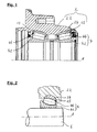
- FIG. 2 a preferred embodiment of the wheel bearing assemblies according to the invention is shown, wherein an axle unit 6 via a bearing unit 4 and a support member 24 is fixed to the hub body 22.
- the bearing unit 4 has a bearing inner ring 42 and rolling elements 44, wherein the rolling element 44 shown is barrel-shaped.
- the support element 24 is also shown, wherein the running surface 25 facing towards the rolling body 44 has a concave shape and the outer surface of the support element 24 facing towards the hub body 22 has a convex shape in the sectional view.
- the outer surface of the support element 24 also be circular or ball-shaped geometries or more complex, the voltage curve in the support member 24 adapted geometries of the outer surface, in which provided in the sectional view, for example, first a cross-sectional increase with subsequent decrease and then turn following increase in the thickness of the support member 24 be. Not shown in the figure are possibly to be provided stops or fasteners to set the bearing inner ring 42 against displacement relative to the axle unit 6.
- FIG. 3 shows a partially sectioned perspective view of an embodiment of the wheel bearing assembly according to the invention, in particular, the recesses or projections, which are provided on the contact surface between the support member 24 and hub body 22 can be seen.
- These recesses or projections 26, in Fig. 1 shown by dashed lines, serve primarily to secure the support member 24 against displacement or rotation relative to the hub body 22.
- the storage unit 4 Further shown in the figure is the storage unit 4, but the view of the rolling elements 44 by a at the front of the storage unit 4 existing seal is blocked.
Landscapes
- Engineering & Computer Science (AREA)
- General Engineering & Computer Science (AREA)
- Mechanical Engineering (AREA)
- Manufacturing & Machinery (AREA)
- Rolling Contact Bearings (AREA)
Applications Claiming Priority (1)
| Application Number | Priority Date | Filing Date | Title |
|---|---|---|---|
| DE201110078713 DE102011078713B4 (de) | 2011-07-06 | 2011-07-06 | Radlageranordnung |
Publications (3)
| Publication Number | Publication Date |
|---|---|
| EP2543900A2 true EP2543900A2 (fr) | 2013-01-09 |
| EP2543900A3 EP2543900A3 (fr) | 2013-05-15 |
| EP2543900B1 EP2543900B1 (fr) | 2015-10-07 |
Family
ID=46465038
Family Applications (1)
| Application Number | Title | Priority Date | Filing Date |
|---|---|---|---|
| EP12172862.0A Not-in-force EP2543900B1 (fr) | 2011-07-06 | 2012-06-21 | Agencement de roulement de roue |
Country Status (2)
| Country | Link |
|---|---|
| EP (1) | EP2543900B1 (fr) |
| DE (1) | DE102011078713B4 (fr) |
Cited By (1)
| Publication number | Priority date | Publication date | Assignee | Title |
|---|---|---|---|---|
| US20160031259A1 (en) * | 2014-07-30 | 2016-02-04 | Honeywell International Inc. | Wheel hub bearing bore |
Families Citing this family (1)
| Publication number | Priority date | Publication date | Assignee | Title |
|---|---|---|---|---|
| ITTO20131001A1 (it) | 2013-12-05 | 2015-06-06 | Skf Ab | Gruppo cuscinetto-mozzo per uso agricolo |
Family Cites Families (4)
| Publication number | Priority date | Publication date | Assignee | Title |
|---|---|---|---|---|
| US2556412A (en) * | 1948-10-15 | 1951-06-12 | Dodge Mfg Corp | Ball-bearing shifter collar |
| FR1350297A (fr) * | 1963-03-06 | 1964-01-24 | Roues libres pour cycles ou motocycles à roulements indéréglables | |
| JP2003120691A (ja) * | 2001-10-12 | 2003-04-23 | Viv Engineering Kk | スタッドローラおよびローラの成形方法 |
| DE102009031625B4 (de) * | 2009-07-03 | 2011-06-01 | Aktiebolaget Skf | Wälzlageranordnung und Kraftfahrzeug-Radnabe |
-
2011
- 2011-07-06 DE DE201110078713 patent/DE102011078713B4/de active Active
-
2012
- 2012-06-21 EP EP12172862.0A patent/EP2543900B1/fr not_active Not-in-force
Non-Patent Citations (1)
| Title |
|---|
| None |
Cited By (4)
| Publication number | Priority date | Publication date | Assignee | Title |
|---|---|---|---|---|
| US20160031259A1 (en) * | 2014-07-30 | 2016-02-04 | Honeywell International Inc. | Wheel hub bearing bore |
| CN105317852A (zh) * | 2014-07-30 | 2016-02-10 | 霍尼韦尔国际公司 | 轮毂轴承孔 |
| US10300740B2 (en) * | 2014-07-30 | 2019-05-28 | Honeywell International Inc. | Wheel hub bearing bore |
| CN105317852B (zh) * | 2014-07-30 | 2019-11-19 | 霍尼韦尔国际公司 | 轮毂轴承孔 |
Also Published As
| Publication number | Publication date |
|---|---|
| EP2543900A3 (fr) | 2013-05-15 |
| DE102011078713B4 (de) | 2014-10-30 |
| EP2543900B1 (fr) | 2015-10-07 |
| DE102011078713A1 (de) | 2013-01-10 |
Similar Documents
| Publication | Publication Date | Title |
|---|---|---|
| WO2012019799A1 (fr) | Unité roulement de roue | |
| WO2007087775A1 (fr) | Palier à roulement asymétrique à trois rangées | |
| EP3509872B1 (fr) | Roue ferroviaire élastique en plusieurs parties | |
| DE102009042941A1 (de) | Schrägrollenlager ohne Führungsbord am Innenring | |
| DE112009002345T5 (de) | Verarbeitung von Videodaten in Geräten mit eingeschränkten Ressourcen | |
| WO2011064062A1 (fr) | Palier à roulement muni de saillies du type bosse appliquées sur la bague extérieure de palier | |
| EP2126388B1 (fr) | Palier a roulement | |
| DE102012004329A1 (de) | Anordnung zur Lagerung von gegeneinander verdrehbaren Teilen einer Energieanlage | |
| WO2006119738A1 (fr) | Roulement a galets coniques a quatre rangees | |
| EP1837536A2 (fr) | Roulement à rouleaux à contact oblique | |
| DE102017205537A1 (de) | Radlagereinheit mit Rotornabe | |
| WO2009129769A2 (fr) | Palier à roulement présentant des surfaces de contact courbes | |
| DE2306650C3 (de) | Schienenrad mit einer Radscheibe | |
| EP1806517A1 (fr) | Articulation en métal et élastomère, en particulier articulation centrale d'un bras de suspension triangulaire d'un axe pour connecter un corps d'axe à une carrosserie de véhicule | |
| EP2543900B1 (fr) | Agencement de roulement de roue | |
| DE102009005389A1 (de) | Pendelrollenlager mit Rollen und Verfahren zum Einbau der Rollen in das Pendelrollenlager | |
| DE102007009918A1 (de) | Radlager mit mehreren Wälzkörperreihen | |
| EP3212436B1 (fr) | Roue ferroviaire et véhicule ferroviaire | |
| DE102010034618A1 (de) | Wälzlager, Wälzkörper und Herstellungsverfahren für die Wälzkörper | |
| DE102010042849A1 (de) | Lagerkäfig und Verfahren zur Herstellung desselben | |
| DE102013215128A1 (de) | Wälzkörper | |
| DE102010011462A1 (de) | Kegelrollenlager mit profilierter Laufbahn | |
| WO2007088144A2 (fr) | Palier à bagues minces | |
| DE102013222833A1 (de) | Stützlageranordnung für ein Planetendifferential | |
| DE102007001799A1 (de) | Radlagervorrichtung |
Legal Events
| Date | Code | Title | Description |
|---|---|---|---|
| PUAI | Public reference made under article 153(3) epc to a published international application that has entered the european phase |
Free format text: ORIGINAL CODE: 0009012 |
|
| AK | Designated contracting states |
Kind code of ref document: A2 Designated state(s): AL AT BE BG CH CY CZ DE DK EE ES FI FR GB GR HR HU IE IS IT LI LT LU LV MC MK MT NL NO PL PT RO RS SE SI SK SM TR |
|
| AX | Request for extension of the european patent |
Extension state: BA ME |
|
| PUAL | Search report despatched |
Free format text: ORIGINAL CODE: 0009013 |
|
| AK | Designated contracting states |
Kind code of ref document: A3 Designated state(s): AL AT BE BG CH CY CZ DE DK EE ES FI FR GB GR HR HU IE IS IT LI LT LU LV MC MK MT NL NO PL PT RO RS SE SI SK SM TR |
|
| AX | Request for extension of the european patent |
Extension state: BA ME |
|
| RIC1 | Information provided on ipc code assigned before grant |
Ipc: F16C 33/60 20060101AFI20130409BHEP Ipc: F16C 35/067 20060101ALI20130409BHEP Ipc: F16C 19/38 20060101ALI20130409BHEP Ipc: B60B 27/00 20060101ALI20130409BHEP Ipc: F16D 3/16 20060101ALI20130409BHEP Ipc: F16C 33/64 20060101ALI20130409BHEP |
|
| 17P | Request for examination filed |
Effective date: 20130917 |
|
| RBV | Designated contracting states (corrected) |
Designated state(s): AL AT BE BG CH CY CZ DE DK EE ES FI FR GB GR HR HU IE IS IT LI LT LU LV MC MK MT NL NO PL PT RO RS SE SI SK SM TR |
|
| 17Q | First examination report despatched |
Effective date: 20140729 |
|
| GRAP | Despatch of communication of intention to grant a patent |
Free format text: ORIGINAL CODE: EPIDOSNIGR1 |
|
| RIC1 | Information provided on ipc code assigned before grant |
Ipc: F16C 33/64 20060101ALI20150409BHEP Ipc: F16C 19/38 20060101ALI20150409BHEP Ipc: F16C 35/067 20060101ALI20150409BHEP Ipc: F16C 33/60 20060101AFI20150409BHEP Ipc: F16D 3/16 20060101ALI20150409BHEP Ipc: B60B 27/00 20060101ALI20150409BHEP |
|
| INTG | Intention to grant announced |
Effective date: 20150505 |
|
| GRAS | Grant fee paid |
Free format text: ORIGINAL CODE: EPIDOSNIGR3 |
|
| GRAA | (expected) grant |
Free format text: ORIGINAL CODE: 0009210 |
|
| AK | Designated contracting states |
Kind code of ref document: B1 Designated state(s): AL AT BE BG CH CY CZ DE DK EE ES FI FR GB GR HR HU IE IS IT LI LT LU LV MC MK MT NL NO PL PT RO RS SE SI SK SM TR |
|
| REG | Reference to a national code |
Ref country code: GB Ref legal event code: FG4D Free format text: NOT ENGLISH |
|
| REG | Reference to a national code |
Ref country code: AT Ref legal event code: REF Ref document number: 753943 Country of ref document: AT Kind code of ref document: T Effective date: 20151015 Ref country code: CH Ref legal event code: EP |
|
| REG | Reference to a national code |
Ref country code: IE Ref legal event code: FG4D Free format text: LANGUAGE OF EP DOCUMENT: GERMAN |
|
| REG | Reference to a national code |
Ref country code: DE Ref legal event code: R096 Ref document number: 502012004806 Country of ref document: DE |
|
| REG | Reference to a national code |
Ref country code: NL Ref legal event code: MP Effective date: 20151007 |
|
| REG | Reference to a national code |
Ref country code: LT Ref legal event code: MG4D |
|
| PG25 | Lapsed in a contracting state [announced via postgrant information from national office to epo] |
Ref country code: IS Free format text: LAPSE BECAUSE OF FAILURE TO SUBMIT A TRANSLATION OF THE DESCRIPTION OR TO PAY THE FEE WITHIN THE PRESCRIBED TIME-LIMIT Effective date: 20160207 Ref country code: NO Free format text: LAPSE BECAUSE OF FAILURE TO SUBMIT A TRANSLATION OF THE DESCRIPTION OR TO PAY THE FEE WITHIN THE PRESCRIBED TIME-LIMIT Effective date: 20160107 Ref country code: HR Free format text: LAPSE BECAUSE OF FAILURE TO SUBMIT A TRANSLATION OF THE DESCRIPTION OR TO PAY THE FEE WITHIN THE PRESCRIBED TIME-LIMIT Effective date: 20151007 Ref country code: LT Free format text: LAPSE BECAUSE OF FAILURE TO SUBMIT A TRANSLATION OF THE DESCRIPTION OR TO PAY THE FEE WITHIN THE PRESCRIBED TIME-LIMIT Effective date: 20151007 Ref country code: ES Free format text: LAPSE BECAUSE OF FAILURE TO SUBMIT A TRANSLATION OF THE DESCRIPTION OR TO PAY THE FEE WITHIN THE PRESCRIBED TIME-LIMIT Effective date: 20151007 Ref country code: IT Free format text: LAPSE BECAUSE OF FAILURE TO SUBMIT A TRANSLATION OF THE DESCRIPTION OR TO PAY THE FEE WITHIN THE PRESCRIBED TIME-LIMIT Effective date: 20151007 Ref country code: NL Free format text: LAPSE BECAUSE OF FAILURE TO SUBMIT A TRANSLATION OF THE DESCRIPTION OR TO PAY THE FEE WITHIN THE PRESCRIBED TIME-LIMIT Effective date: 20151007 |
|
| PG25 | Lapsed in a contracting state [announced via postgrant information from national office to epo] |
Ref country code: PT Free format text: LAPSE BECAUSE OF FAILURE TO SUBMIT A TRANSLATION OF THE DESCRIPTION OR TO PAY THE FEE WITHIN THE PRESCRIBED TIME-LIMIT Effective date: 20160208 Ref country code: GR Free format text: LAPSE BECAUSE OF FAILURE TO SUBMIT A TRANSLATION OF THE DESCRIPTION OR TO PAY THE FEE WITHIN THE PRESCRIBED TIME-LIMIT Effective date: 20160108 Ref country code: PL Free format text: LAPSE BECAUSE OF FAILURE TO SUBMIT A TRANSLATION OF THE DESCRIPTION OR TO PAY THE FEE WITHIN THE PRESCRIBED TIME-LIMIT Effective date: 20151007 Ref country code: FI Free format text: LAPSE BECAUSE OF FAILURE TO SUBMIT A TRANSLATION OF THE DESCRIPTION OR TO PAY THE FEE WITHIN THE PRESCRIBED TIME-LIMIT Effective date: 20151007 Ref country code: SE Free format text: LAPSE BECAUSE OF FAILURE TO SUBMIT A TRANSLATION OF THE DESCRIPTION OR TO PAY THE FEE WITHIN THE PRESCRIBED TIME-LIMIT Effective date: 20151007 Ref country code: LV Free format text: LAPSE BECAUSE OF FAILURE TO SUBMIT A TRANSLATION OF THE DESCRIPTION OR TO PAY THE FEE WITHIN THE PRESCRIBED TIME-LIMIT Effective date: 20151007 Ref country code: RS Free format text: LAPSE BECAUSE OF FAILURE TO SUBMIT A TRANSLATION OF THE DESCRIPTION OR TO PAY THE FEE WITHIN THE PRESCRIBED TIME-LIMIT Effective date: 20151007 |
|
| REG | Reference to a national code |
Ref country code: FR Ref legal event code: PLFP Year of fee payment: 5 |
|
| REG | Reference to a national code |
Ref country code: DE Ref legal event code: R097 Ref document number: 502012004806 Country of ref document: DE |
|
| PG25 | Lapsed in a contracting state [announced via postgrant information from national office to epo] |
Ref country code: CZ Free format text: LAPSE BECAUSE OF FAILURE TO SUBMIT A TRANSLATION OF THE DESCRIPTION OR TO PAY THE FEE WITHIN THE PRESCRIBED TIME-LIMIT Effective date: 20151007 |
|
| PLBE | No opposition filed within time limit |
Free format text: ORIGINAL CODE: 0009261 |
|
| STAA | Information on the status of an ep patent application or granted ep patent |
Free format text: STATUS: NO OPPOSITION FILED WITHIN TIME LIMIT |
|
| PG25 | Lapsed in a contracting state [announced via postgrant information from national office to epo] |
Ref country code: RO Free format text: LAPSE BECAUSE OF FAILURE TO SUBMIT A TRANSLATION OF THE DESCRIPTION OR TO PAY THE FEE WITHIN THE PRESCRIBED TIME-LIMIT Effective date: 20151007 Ref country code: EE Free format text: LAPSE BECAUSE OF FAILURE TO SUBMIT A TRANSLATION OF THE DESCRIPTION OR TO PAY THE FEE WITHIN THE PRESCRIBED TIME-LIMIT Effective date: 20151007 Ref country code: SM Free format text: LAPSE BECAUSE OF FAILURE TO SUBMIT A TRANSLATION OF THE DESCRIPTION OR TO PAY THE FEE WITHIN THE PRESCRIBED TIME-LIMIT Effective date: 20151007 Ref country code: DK Free format text: LAPSE BECAUSE OF FAILURE TO SUBMIT A TRANSLATION OF THE DESCRIPTION OR TO PAY THE FEE WITHIN THE PRESCRIBED TIME-LIMIT Effective date: 20151007 Ref country code: SK Free format text: LAPSE BECAUSE OF FAILURE TO SUBMIT A TRANSLATION OF THE DESCRIPTION OR TO PAY THE FEE WITHIN THE PRESCRIBED TIME-LIMIT Effective date: 20151007 |
|
| 26N | No opposition filed |
Effective date: 20160708 |
|
| PG25 | Lapsed in a contracting state [announced via postgrant information from national office to epo] |
Ref country code: SI Free format text: LAPSE BECAUSE OF FAILURE TO SUBMIT A TRANSLATION OF THE DESCRIPTION OR TO PAY THE FEE WITHIN THE PRESCRIBED TIME-LIMIT Effective date: 20151007 |
|
| PG25 | Lapsed in a contracting state [announced via postgrant information from national office to epo] |
Ref country code: BE Free format text: LAPSE BECAUSE OF NON-PAYMENT OF DUE FEES Effective date: 20160630 |
|
| PG25 | Lapsed in a contracting state [announced via postgrant information from national office to epo] |
Ref country code: MC Free format text: LAPSE BECAUSE OF FAILURE TO SUBMIT A TRANSLATION OF THE DESCRIPTION OR TO PAY THE FEE WITHIN THE PRESCRIBED TIME-LIMIT Effective date: 20151007 |
|
| REG | Reference to a national code |
Ref country code: CH Ref legal event code: PL |
|
| REG | Reference to a national code |
Ref country code: IE Ref legal event code: MM4A |
|
| PG25 | Lapsed in a contracting state [announced via postgrant information from national office to epo] |
Ref country code: CH Free format text: LAPSE BECAUSE OF NON-PAYMENT OF DUE FEES Effective date: 20160630 Ref country code: LI Free format text: LAPSE BECAUSE OF NON-PAYMENT OF DUE FEES Effective date: 20160630 |
|
| PG25 | Lapsed in a contracting state [announced via postgrant information from national office to epo] |
Ref country code: IE Free format text: LAPSE BECAUSE OF NON-PAYMENT OF DUE FEES Effective date: 20160621 |
|
| REG | Reference to a national code |
Ref country code: FR Ref legal event code: PLFP Year of fee payment: 6 |
|
| PG25 | Lapsed in a contracting state [announced via postgrant information from national office to epo] |
Ref country code: CY Free format text: LAPSE BECAUSE OF FAILURE TO SUBMIT A TRANSLATION OF THE DESCRIPTION OR TO PAY THE FEE WITHIN THE PRESCRIBED TIME-LIMIT Effective date: 20151007 Ref country code: HU Free format text: LAPSE BECAUSE OF FAILURE TO SUBMIT A TRANSLATION OF THE DESCRIPTION OR TO PAY THE FEE WITHIN THE PRESCRIBED TIME-LIMIT; INVALID AB INITIO Effective date: 20120621 |
|
| REG | Reference to a national code |
Ref country code: FR Ref legal event code: PLFP Year of fee payment: 7 |
|
| PG25 | Lapsed in a contracting state [announced via postgrant information from national office to epo] |
Ref country code: MT Free format text: LAPSE BECAUSE OF FAILURE TO SUBMIT A TRANSLATION OF THE DESCRIPTION OR TO PAY THE FEE WITHIN THE PRESCRIBED TIME-LIMIT Effective date: 20151007 Ref country code: LU Free format text: LAPSE BECAUSE OF NON-PAYMENT OF DUE FEES Effective date: 20160621 Ref country code: MK Free format text: LAPSE BECAUSE OF FAILURE TO SUBMIT A TRANSLATION OF THE DESCRIPTION OR TO PAY THE FEE WITHIN THE PRESCRIBED TIME-LIMIT Effective date: 20151007 Ref country code: TR Free format text: LAPSE BECAUSE OF FAILURE TO SUBMIT A TRANSLATION OF THE DESCRIPTION OR TO PAY THE FEE WITHIN THE PRESCRIBED TIME-LIMIT Effective date: 20151007 |
|
| PG25 | Lapsed in a contracting state [announced via postgrant information from national office to epo] |
Ref country code: BG Free format text: LAPSE BECAUSE OF FAILURE TO SUBMIT A TRANSLATION OF THE DESCRIPTION OR TO PAY THE FEE WITHIN THE PRESCRIBED TIME-LIMIT Effective date: 20151007 |
|
| REG | Reference to a national code |
Ref country code: AT Ref legal event code: MM01 Ref document number: 753943 Country of ref document: AT Kind code of ref document: T Effective date: 20170621 |
|
| PG25 | Lapsed in a contracting state [announced via postgrant information from national office to epo] |
Ref country code: AL Free format text: LAPSE BECAUSE OF FAILURE TO SUBMIT A TRANSLATION OF THE DESCRIPTION OR TO PAY THE FEE WITHIN THE PRESCRIBED TIME-LIMIT Effective date: 20151007 |
|
| PG25 | Lapsed in a contracting state [announced via postgrant information from national office to epo] |
Ref country code: AT Free format text: LAPSE BECAUSE OF NON-PAYMENT OF DUE FEES Effective date: 20170621 |
|
| PGFP | Annual fee paid to national office [announced via postgrant information from national office to epo] |
Ref country code: FR Payment date: 20200623 Year of fee payment: 9 Ref country code: DE Payment date: 20200417 Year of fee payment: 9 |
|
| PGFP | Annual fee paid to national office [announced via postgrant information from national office to epo] |
Ref country code: GB Payment date: 20200625 Year of fee payment: 9 |
|
| REG | Reference to a national code |
Ref country code: DE Ref legal event code: R119 Ref document number: 502012004806 Country of ref document: DE |
|
| GBPC | Gb: european patent ceased through non-payment of renewal fee |
Effective date: 20210621 |
|
| PG25 | Lapsed in a contracting state [announced via postgrant information from national office to epo] |
Ref country code: GB Free format text: LAPSE BECAUSE OF NON-PAYMENT OF DUE FEES Effective date: 20210621 Ref country code: DE Free format text: LAPSE BECAUSE OF NON-PAYMENT OF DUE FEES Effective date: 20220101 |
|
| PG25 | Lapsed in a contracting state [announced via postgrant information from national office to epo] |
Ref country code: FR Free format text: LAPSE BECAUSE OF NON-PAYMENT OF DUE FEES Effective date: 20210630 |