EP2541367A2 - Ladebrücke für tragbare elektronische Vorrichtung - Google Patents
Ladebrücke für tragbare elektronische Vorrichtung Download PDFInfo
- Publication number
- EP2541367A2 EP2541367A2 EP11191015A EP11191015A EP2541367A2 EP 2541367 A2 EP2541367 A2 EP 2541367A2 EP 11191015 A EP11191015 A EP 11191015A EP 11191015 A EP11191015 A EP 11191015A EP 2541367 A2 EP2541367 A2 EP 2541367A2
- Authority
- EP
- European Patent Office
- Prior art keywords
- connector
- dock
- charging connector
- portable electronic
- electronic device
- Prior art date
- Legal status (The legal status is an assumption and is not a legal conclusion. Google has not performed a legal analysis and makes no representation as to the accuracy of the status listed.)
- Granted
Links
- 230000004044 response Effects 0.000 claims abstract description 9
- 230000008878 coupling Effects 0.000 claims description 7
- 238000010168 coupling process Methods 0.000 claims description 7
- 238000005859 coupling reaction Methods 0.000 claims description 7
- 239000000463 material Substances 0.000 claims description 7
- CWYNVVGOOAEACU-UHFFFAOYSA-N Fe2+ Chemical compound [Fe+2] CWYNVVGOOAEACU-UHFFFAOYSA-N 0.000 claims description 6
- 238000010292 electrical insulation Methods 0.000 claims description 5
- 230000013011 mating Effects 0.000 description 22
- 238000004891 communication Methods 0.000 description 15
- 238000012546 transfer Methods 0.000 description 6
- 230000003287 optical effect Effects 0.000 description 4
- 230000001413 cellular effect Effects 0.000 description 3
- 230000006870 function Effects 0.000 description 3
- 238000000034 method Methods 0.000 description 3
- 239000000853 adhesive Substances 0.000 description 2
- 230000001070 adhesive effect Effects 0.000 description 2
- 238000010586 diagram Methods 0.000 description 2
- 230000000694 effects Effects 0.000 description 2
- 239000004033 plastic Substances 0.000 description 2
- 229920003023 plastic Polymers 0.000 description 2
- 229920006311 Urethane elastomer Polymers 0.000 description 1
- 239000000654 additive Substances 0.000 description 1
- 230000000996 additive effect Effects 0.000 description 1
- 230000004075 alteration Effects 0.000 description 1
- 238000006243 chemical reaction Methods 0.000 description 1
- 239000004020 conductor Substances 0.000 description 1
- 239000007799 cork Substances 0.000 description 1
- 230000005489 elastic deformation Effects 0.000 description 1
- 239000003292 glue Substances 0.000 description 1
- 230000005484 gravity Effects 0.000 description 1
- 239000002184 metal Substances 0.000 description 1
- 238000012986 modification Methods 0.000 description 1
- 230000004048 modification Effects 0.000 description 1
- 239000002991 molded plastic Substances 0.000 description 1
- 230000002085 persistent effect Effects 0.000 description 1
- 229920002635 polyurethane Polymers 0.000 description 1
- 239000004814 polyurethane Substances 0.000 description 1
- 230000008569 process Effects 0.000 description 1
- 238000012545 processing Methods 0.000 description 1
- 230000002441 reversible effect Effects 0.000 description 1
- 229920002379 silicone rubber Polymers 0.000 description 1
- 239000004945 silicone rubber Substances 0.000 description 1
- 229910000679 solder Inorganic materials 0.000 description 1
- 238000003466 welding Methods 0.000 description 1
- 239000002023 wood Substances 0.000 description 1
Images


Classifications
-
- G—PHYSICS
- G06—COMPUTING; CALCULATING OR COUNTING
- G06F—ELECTRIC DIGITAL DATA PROCESSING
- G06F1/00—Details not covered by groups G06F3/00 - G06F13/00 and G06F21/00
- G06F1/16—Constructional details or arrangements
-
- G—PHYSICS
- G06—COMPUTING; CALCULATING OR COUNTING
- G06F—ELECTRIC DIGITAL DATA PROCESSING
- G06F1/00—Details not covered by groups G06F3/00 - G06F13/00 and G06F21/00
- G06F1/16—Constructional details or arrangements
- G06F1/1613—Constructional details or arrangements for portable computers
- G06F1/1632—External expansion units, e.g. docking stations
-
- G—PHYSICS
- G06—COMPUTING; CALCULATING OR COUNTING
- G06F—ELECTRIC DIGITAL DATA PROCESSING
- G06F1/00—Details not covered by groups G06F3/00 - G06F13/00 and G06F21/00
- G06F1/16—Constructional details or arrangements
- G06F1/1613—Constructional details or arrangements for portable computers
- G06F1/1626—Constructional details or arrangements for portable computers with a single-body enclosure integrating a flat display, e.g. Personal Digital Assistants [PDAs]
-
- G—PHYSICS
- G06—COMPUTING; CALCULATING OR COUNTING
- G06F—ELECTRIC DIGITAL DATA PROCESSING
- G06F1/00—Details not covered by groups G06F3/00 - G06F13/00 and G06F21/00
- G06F1/16—Constructional details or arrangements
- G06F1/1613—Constructional details or arrangements for portable computers
- G06F1/1633—Constructional details or arrangements of portable computers not specific to the type of enclosures covered by groups G06F1/1615 - G06F1/1626
- G06F1/1656—Details related to functional adaptations of the enclosure, e.g. to provide protection against EMI, shock, water, or to host detachable peripherals like a mouse or removable expansions units like PCMCIA cards, or to provide access to internal components for maintenance or to removable storage supports like CDs or DVDs, or to mechanically mount accessories
- G06F1/166—Details related to functional adaptations of the enclosure, e.g. to provide protection against EMI, shock, water, or to host detachable peripherals like a mouse or removable expansions units like PCMCIA cards, or to provide access to internal components for maintenance or to removable storage supports like CDs or DVDs, or to mechanically mount accessories related to integrated arrangements for adjusting the position of the main body with respect to the supporting surface, e.g. legs for adjusting the tilt angle
-
- H—ELECTRICITY
- H01—ELECTRIC ELEMENTS
- H01R—ELECTRICALLY-CONDUCTIVE CONNECTIONS; STRUCTURAL ASSOCIATIONS OF A PLURALITY OF MUTUALLY-INSULATED ELECTRICAL CONNECTING ELEMENTS; COUPLING DEVICES; CURRENT COLLECTORS
- H01R31/00—Coupling parts supported only by co-operation with counterpart
- H01R31/06—Intermediate parts for linking two coupling parts, e.g. adapter
Definitions
- the present application relates to charging and/or data transfer docks for portable electronic devices.
- Portable electronic devices include, for example, several types of mobile stations such as simple cellular telephones, smart telephones, wireless personal digital assistants (PDAs), tablets and laptop computers with wireless 802.11 or Bluetooth capabilities.
- PIM personal information manager
- Portable electronic devices such as PDAs or smart telephones are generally intended for handheld use (that is, the devices are sized and shaped to be held or carried in a human hand) and ease of portability.
- Portable electronic devices are often placed in docks for charging or data transfer including transfer of information in any form optically or electrically from dock to portable electronic device and vice versa.
- Some docks are capable of both charging and data transfer. Docks and portable electronic devices are susceptible to damage due to connection attempts when the portable electronic device and the dock are not properly aligned.
- a dock for receiving a portable electronic device including a housing comprising an aperture; a support coupled to an inner wall of the housing; and a charging connector received in the support and movable relative to the housing for charging the portable electronic device when the charging connector extends through the aperture, wiring of the charging connector for electrically communicating with a power source; wherein the charging connector is movable relative to the housing in response to a magnetic force.
- a connector assembly for a dock including: a support for coupling to an inner wall the dock; and a charging connector received in the support and movable relative to the dock in response to a magnetic force, the charging connector for charging a portable electronic device when the charging connector extends through an aperture of the dock, wiring of the charging connector for electrically communicating with a power source.
- the charging connector is in an extended position when charging and is biased toward a stowed position under the weight of the charging connector when not charging.
- FIG.1 is a simplified block diagram of components including internal components of a portable electronic device
- FIG. 2 is an isometric view of a portable electronic device received in a dock according to an example
- FIG. 3 is a side view of a portable electronic device received in the dock of FIG. 2 with a portion of a housing of the dock removed;
- FIG. 4 is a side sectional view of portions of the dock of FIG. 2 with a charging connector in a stowed position;
- FIG. 5 is a side sectional view of portions of the dock of FIG.2 with a charging connector in an extended position
- FIG. 7 is an isometric view of the dock of FIG. 6 with the charging connector in an extended position
- FIG. 8 is a front sectional view of the dock of FIG. 6 ;
- FIG. 9 is an exploded isometric view of the dock of FIG. 6 ;
- FIG. 10 is an isometric top sectional view of the dock of FIG. 6 ;
- FIG. 11 is a isometric side sectional view of the dock of FIG. 6 with the charging connector in the stowed position;
- FIG. 12 is a isometric side sectional view of the dock of FIG. 6 with the charging connector in the extended position;
- FIG. 13 is an isometric rear bottom view of the dock of FIG. 6 ;
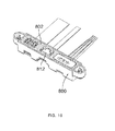
- FIG. 14 is an isometric view similar to FIG. 12 including additional components of the dock.
- the dock for receiving a portable electronic device.
- the dock includes a charging connector moveable under a magnetic force into contact with a mating connector of the portable electronic device.
- the disclosure generally relates to a dock for a portable electronic device in the embodiments described herein.
- the dock may receive portable electronic devices including: mobile, or handheld, wireless communication devices such as pagers, cellular phones, cellular smartphones, wireless organizers, tablets, global positioning system devices and personal digital assistants, for example.
- the portable electronic device may also be a portable electronic device without wireless communication capabilities, such as a handheld electronic game device, digital photograph album, digital camera, or other device.
- the portable electronic device may be, but need not be, a handheld device.
- FIG. 1 A block diagram of an example of a portable electronic device 100 is shown in FIG. 1 .
- the portable electronic device 100 includes multiple components, such as a processor 102 that controls the overall operation of the portable electronic device 100. Communication functions, including data and voice communications, are performed through a communication subsystem 104. Data received by the portable electronic device 100 is decompressed and decrypted by a decoder 106.
- the communication subsystem 104 receives messages from and sends messages to a wireless network 120.
- the wireless network 120 may be any type of wireless network, including, but not limited to, data wireless networks, voice wireless networks, and networks that support both voice and data communications.
- a power pack 122 powers the portable electronic device 100.
- a dock interface 140 may electrically communicate with a dock 150 to charge the power pack 122 and/or provide a data connection to a data port 126 of the portable electronic device 100.
- components electrically communicate with one another when the electrical activity in one component affects an electrical activity in another. Electrical communication includes direct electrical contact that enables current flow.
- the dock interface 140 may include one or more mating connectors for electrically communicating with connectors of the dock 150.
- the dock 150 may communicate with one or more of a power source 142, multimedia devices 144 such as televisions, monitors, projectors or other output devices, for example, and other electronic devices 146. In some situations, communication may be electrical or optical or a combination of electrical and optical.
- the processor 102 interacts with other components, such as Random Access Memory (RAM) 108, memory 110, a display 112, an input device 114, an auxiliary input/output (I/O) subsystem 124, the data port 126, a speaker 128, a microphone 130, short-range communications 132, and other device subsystems 134.
- RAM Random Access Memory
- I/O auxiliary input/output
- the processor 102 may interact with an orientation sensor such as an accelerometer 136 that may be utilized to detect direction of gravitational forces or gravity-induced reaction forces.
- the portable electronic device 100 uses a Subscriber Identity Module or a Removable User Identity Module (SIM/RUIM) card 138 for communication with a network, such as the wireless network 120.
- SIM/RUIM Removable User Identity Module
- user identification information may be programmed into memory 110.
- the portable electronic device 100 includes an operating system 116 and software programs or components 118 that are executed by the processor 102 and are typically stored in a persistent, updatable store such as the memory 110. Additional applications or programs may be loaded onto the portable electronic device 100 through the wireless network 120, the auxiliary I/O subsystem 124, the data port 126, the short-range communications subsystem 132, or any other suitable subsystem 134.
- a received signal such as a text message, an e-mail message, or web page download is processed by the communication subsystem 104 and input to the processor 102.
- the processor 102 processes the received signal for output to the display 112 and/or to the auxiliary I/O subsystem 124.
- a subscriber may generate data items, for example e-mail messages, which may be transmitted over the wireless network 120 through the communication subsystem 104.
- the speaker 128 outputs audible information converted from electrical signals
- the microphone 130 converts audible information into electrical signals for processing.
- the dock 150 includes a housing 200 that is shaped to receive the portable electronic device 100.
- the housing 200 includes a seat 302 and a support wall 300 for receiving the portable electronic device 100.
- the support wall 300 and the seat 302 support the weight of a received portable electronic device 100, although in some of the embodiments depicted herein, the seat 302 may support more weight than the support wall 300.
- an edge surface 304 of the portable electronic device 100 contacts the seat 302 of the housing 200 and a rear surface 306 of the portable electronic device 100 contacts the support wall 300 of the housing 200.
- the size and shape of the seat 302 and the support wall 300 and the angle between the seat 302 and the support wall 300 may be selected to accommodate different sizes and types of portable electronic devices 100.
- the housing 200 may be molded plastic, machined metal or wood, for example.
- the housing may be a single part or may be an assembly of multiple parts.
- the dock 150 includes a connector support assembly 308 that is coupled to an inner surface of the housing 200.
- components are coupled to one another when movement of one component affects movement in the other component.
- Coupling may be permanent, such as by welding for example, or may be reversible, such as connection by fasteners, for example. Coupling may include direct contact between the two components or the components may be spaced from one another with additional components being provided to achieve coupling between the two components.
- screws 310 couple lugs 312 of the support assembly 308 to screw-receiving components 314, which extend from an underside surface 316 of the seat 302, to couple the support assembly 308 to the housing 200.
- the connector support assembly 308 receives a charging connector 400.
- the charging connector 400 may be capable of charging and data transfer.
- a connecting portion of the charging connector 400 may extend through an aperture 402, which is located in the seat 302.
- the charging connector 400 electrically communicates with the portable electronic device 100 to charge the portable electronic device 100 and/or provide a data connection thereto.
- the portable electronic device 100 is received in the dock 150 when the portable electronic device 100 is generally supported thereby.
- a first component may be received in a second component when the first component is supported by the second component. The first component may or may not be coupled to the second component and may move relative to the second component.
- the connector support assembly 308 includes a support 404 including a base 406 having an opening 408 therethrough.
- the support defines a cavity for receiving the charging connector 400.
- the charging connector 400 includes electrical contacts 412 surrounded by a sleeve 414. Electrical insulation (not shown) is provided between the electrical contacts 412 and the sleeve 414.
- the sleeve 414 includes an enlarged base 416.
- the sleeve may be a ferrous material that may be attracted by a magnet on a mating connector of the portable electronic device 100 or may be a magnet for attracting a ferrous material on a mating connector of the portable electronic device 100.
- the electrical contacts 412 are coupled to the sleeve 414 by a press fit, for example. Alternatively, the electrical contacts 412 may be coupled to the sleeve 414 by snap-in parts, threads, or adhesives, for example.
- Wiring 418 extends from the charging connector 400 for electrically communicating with a power supply (not shown), such as an electrical outlet, for example.
- the charging connector 400 is movable through the cavity defined by the support 404 from a stowed position, which is shown in FIG. 4 to an extended position, which is shown in FIG. 5 .
- the charging connector 400 is in the stowed position, or starting position, in the dock 150, the enlarged base 416 of the sleeve 414 abuts an inner surface 420 of the base 406.
- the charging connector 400 is in the extended position, the sleeve 414 is received through the aperture 402 of the dock 150 and the enlarged base 416 may abut an underside of the seat 302.
- the charging connector 400 moves in response to a magnetic force generated by a magnet, which surrounds the electrical contacts of the portable electronic device 100 in one example.
- the magnet has sufficient strength to attract the charging connector 400 of the dock 150, such that charging connector 400 moves automatically from the stowed position to the extended position, and maintain the electrical contacts of the dock 150 in contact with the electrical contacts of the portable electronic device 100.
- the charging connector 400 returns to the stowed position of FIG. 3 under its own weight.
- the charging connector 400 may be biased toward the stowed position by a spring or other biasing device.
- a clearance is provided between the wall defining the aperture 402 and the charging connector 400.
- the charging connector 400 is movable in the z-direction through the aperture 402 and in the x and y directions within the aperture 402.
- a user places the portable electronic device 100 on the seat 302 leaning against support wall 300 of the dock 150 for charging.
- the sleeve 312 of the charging connector 400 is attracted to the magnet and the charging connector 400 moves toward the electrical contacts of the portable electronic device 100.
- the charging connector 400 also moves forward, backward and/or side-to-side in order to compensate for the misalignment between the electrical contacts of the dock 150 and the electrical contacts of the portable electronic device 100. In this way, there may be some automatic compensation for misalignment.
- the support assembly 308 is eliminated and a flange extends from the underside surface of the seat 302.
- the flange includes a return portion that is directed toward the charging connector 400.
- the return portion abuts the enlarged portion 416 of the sleeve 414 when the charging connector 400 is stowed in the housing 200.
- the charging connector 400 is movable from the stowed position to an extended position when a portable electronic device 100 is received in the dock 150.
- the connector extends through an aperture in the support wall or other location in order to accommodate different locations of portable electronic device mating connectors.
- the dock 150 includes apertures 600, 602, 604, which extend through the seat 302 of the housing 200.
- First and second data connectors 606 and 608 extend through apertures 600 and 602, respectively.
- a charging connector 610 extends through the aperture 604.
- the connectors 606, 608, 610 electrically or optically communicate with the portable electronic device 100 to provide data connections and charge the portable electronic device 10.
- the first data connector 606 is a micro HDMI connector for transferring data to multimedia devices and the second data connector 608 is a micro USB connector for exchanging data with other electronic devices. Other types of data connectors are also possible.
- the charging connector 610 may also transfer data.
- the connectors 606, 608, 610 are mounted in a connector support assembly 612, which is coupled to an inner surface of the housing 200.
- screws 616 couple lugs 618 of the support assembly 612 to screw-receiving components 806, which extend from an underside surface 810 of the seat 302, to couple the support assembly 612 to the housing 200.
- Other arrangements for coupling the connector support assembly to the housing 200 are also possible.
- the connector support assembly 612 includes a support tray 800, a spring component 802, which is located in the support tray 800, and a pad 804, which is disposed between a base 808 of the support tray 800 and the spring component 802.
- the spring component 802 includes tabs 620, which mate with openings 822 in front and rear walls of the support tray 800 to generally fix the spring component 802 relative to the support tray 800.
- Alterative arrangements for fixing the spring component 802 in the support tray 800 are possible including fasteners, such as screws, rivets or staples, glue, or other snap-in fastening arrangements.
- the spring component 802 may be sized so that an interference fit is provided between the spring component 802 and the connectors 606, 608.
- the spring component 802 includes passages 900, 902 and 904, which are shown in FIG. 9 .
- the passages 900, 902 and 904 receive first and second data connectors 606, 608 and charging connector 610, respectively.
- Ribs 812 extend from inner walls 814 and 816 of passages 900 and 902 of the spring component 802, respectively. The ribs 812 contact the first and second data connectors 606, 608 in order to maintain the connectors 606, 608 in a starting position within the respective passages 900, 902.
- the spring component 802 is elastically deformable to accommodate movement of the connectors 606, 608 in the x and/or y directions.
- the spring component 802 is biased toward a non-deformed shape, which is shown in FIG.
- the spring component 802 is made from a flexible material such as silicone rubber, urethane rubber or cork, for example.
- a hard plastic having flexible fingers may alternatively be used.
- the base 808 of the support tray 800 limits movement of the connectors 606, 608, 610 in the z-direction to facilitate coupling with mating connectors of the portable electronic device 10.
- the pad 804 is elastically deformable to accommodate some movement of the connector 606 and 608 in the z direction.
- the pad 804 may be interference fit with the connectors 606, 608 to bias the connectors 606, 608 toward the mating connectors of the portable electronic device 100 and absorb tolerances.
- the pad 804 is biased toward a non-deformed shape, which is shown in FIG. 8 , and is compressible in response to a downward, or axial, force on the connectors 606, 608.
- the pad 804 is two-shot or overmolded onto the support tray 800 to reduce the part count of the dock 150.
- apertures 906 extend through the pad 804.
- the apertures 906 are aligned with the through-hole leads of the connectors 606, 608, which protrude through an opposite surface of printed circuit boards (PCB), 908, 910 of the first and second data connectors 606, 608, respectively.
- the apertures 906 generally protect the leads and solder joints of the PCB 908, 910 from stress during assembly and use when the portable electronic device 100 is inserted into and removed from the dock 150.
- the charging connector 610 includes electrical contacts 1100 surrounded by a sleeve 1102.
- An electrical insulation component 1108 is located between electrical contacts 1100 and the sleeve 1102.
- the sleeve 1102 includes an enlarged base 1104.
- the sleeve 1102 may be a ferrous material that may be attracted by a magnet on a mating connector of the portable electronic device 100 or may be a magnet for attracting a ferrous material on a mating connector of the portable electronic device 100.
- the electrical contacts 1100 are coupled to the sleeve 1102 by a press fit, for example. Alternatively, the electrical contacts 1100 may be coupled to the sleeve 1102 by snap-in parts, threads, or adhesives, for example.
- a connector base 1106 is coupled adjacent to the enlarged base 1104 of the sleeve 1102.
- the connector base 1106 is slidable through passage 904.
- the connector base 1106 may be made of a PVC, a polyurethane overmold or may be a separate soft or hard plastic component.
- the support tray 800 includes openings 1300, which extend through a rear wall 1302 of the support tray 800 to allow wiring 1304 of the connectors 606, 608, 610 to extend therethrough.
- the wiring 1304 may be flexible cables, such as electrical conductors or optical cables, for example, coupled between the connectors 606, 608, 610 and an electronic device (not shown), a multimedia device (not shown) and a power source (not shown), respectively.
- the flexible cables are coupled to a connector (not shown) that is mounted on a main PCB 1400 coupled inside the housing 200, as shown in FIG. 14 .
- the flexible cables may alternatively be soldered to the main PCB 1400. When a main PCB is not included, the flexible cables may be soldered, crimped or inserted into mating pins of one or more connectors.
- Wiring for electrically communicating with the electronic device, multimedia device and power source may extend through opening 1402.
- the charging connector 610 is movable in the z direction through the passage 904 between a stowed position, which is shown in FIGS. 6 and 11 , and an extended position, which is shown in FIGS. 7 and 12 .
- the charging connector 610 is a floating connector that is biased toward the stowed position and moveable under a magnetic force to the extended position. As shown in FIGS. 6 and 8 , a clearance is provided between the wall defining the aperture 604 and the charging connector 610.
- the charging connector 610 is movable in the z-direction through the aperture 604 and in the x and y directions within the aperture 604.
- a user visually and/or tactilely aligns mating connectors of the portable electronic device 100 with the connectors 606, 608 and 610 of the dock 150 and then moves the mating connectors into engagement with the connectors 606, 608, 610.
- a force is imparted on one or both of the connectors 606, 608 by the portable electronic device 100.
- the spring component 802 elastically deforms in order to accommodate movement of the one or both of the connectors 606, 608 in response to the force. Multiple forces may be applied to the connectors 606, 608 in various different directions while the user attempts to join the connectors of the portable electronic device 100 and dock 150.
- the charging connector 610 moves toward the mating charging connector of the portable electronic device 100 when the magnet of the mating charging connector is near the charging connector 610.
- the charging connector 400 also moves in the x and y directions in order to compensate for the misalignment between the electrical contacts of the dock 150 with the electrical contacts of the portable electronic device 100.
- the connectors 606, 608 may return to the their starting positions or one or both of the connectors 606, 608 may continue to be offset from the starting position due to the additive tolerances of the mating connectors of the portable electronic device 100.
- the connector 610 remains in the extended position until the portable electronic device 100 is removed from the dock 150.
- the charging connector 610 does not extend outside of the housing 200 when in the stowed position, portable electronic devices that use a different charging arrangement may still couple to the data connectors 606, 608 of the dock 150.
- the connector support assembly and connector(s) may be provided as a single connector assembly that may be mounted in any dock.
- the connector support assembly may be manufactured to meet specifications associated with docks of different portable electronic devices.
- the dock 150 described herein may realize one or more advantages, some of which have already been described.
- the charging connector of the dock 150 facilitates quick and easy connection by allowing a user to place a portable electronic device 100 in the seat 302 and slide the portable electronic device 100 in a direction that aligns a mating connector of the portable electronic device 100 with the charging connector. When the mating connector is close to the charging connector, the charging connector will move toward the mating connector and couple thereto. The user need not locate the portable electronic device perfectly on the dock 150 because the charging connector is able to compensate for some misalignment of the mating connector. Removal of the portable electronic device 100 from the dock is similarly quick and easy.
- the dock 150 may be usable with portable electronic devices that do not support a magnetic charging connection. Because the charging connector is stowed below the seat 302, when the magnetic charging connection is unsupported, no interference between the charging connector and the portable electronic device occurs. This may be particularly useful when the dock 150 includes an additional connector, such as data connector 606, 608. Many different portable electronic devices may include multimedia output capability, for example, and dock 150 is able to connect to such devices even when the devices do not support a magnetic charging connection.
- the connector(s) and connector support assembly may be an independent unit that may be mounted in many different types of housings. In addition, different types of connectors may be mounted in the connector support assembly so that customization for different dock housings is possible.
- Housing 200 supports the portable electronic device 100 in a position that allows a user to interact with the portable electronic device 100. Other dock housings may support the portable electronic device 100 in different positions.
Applications Claiming Priority (1)
| Application Number | Priority Date | Filing Date | Title |
|---|---|---|---|
| US201161503450P | 2011-06-30 | 2011-06-30 |
Publications (3)
| Publication Number | Publication Date |
|---|---|
| EP2541367A2 true EP2541367A2 (de) | 2013-01-02 |
| EP2541367A3 EP2541367A3 (de) | 2014-12-31 |
| EP2541367B1 EP2541367B1 (de) | 2018-08-15 |
Family
ID=45217286
Family Applications (1)
| Application Number | Title | Priority Date | Filing Date |
|---|---|---|---|
| EP11191015.4A Active EP2541367B1 (de) | 2011-06-30 | 2011-11-28 | Ladebrücke für tragbare elektronische Vorrichtung |
Country Status (6)
| Country | Link |
|---|---|
| US (1) | US8853998B2 (de) |
| EP (1) | EP2541367B1 (de) |
| KR (1) | KR101398763B1 (de) |
| CN (1) | CN102854927B (de) |
| CA (1) | CA2780389C (de) |
| MX (1) | MX2012007606A (de) |
Cited By (4)
| Publication number | Priority date | Publication date | Assignee | Title |
|---|---|---|---|---|
| WO2014114020A1 (zh) * | 2013-01-22 | 2014-07-31 | 深圳感臻科技有限公司 | 一种多媒体播放设备 |
| EP2919330A1 (de) * | 2014-03-10 | 2015-09-16 | Hosiden Corporation | Steckverbinder |
| EP3595097A4 (de) * | 2017-03-29 | 2020-04-01 | Huawei Technologies Co., Ltd. | Verbinder, elektronische vorrichtung und elektronische einrichtung |
| WO2023284951A1 (en) * | 2021-07-14 | 2023-01-19 | Huawei Technologies Co., Ltd. | Detachable connection arrangement for connecting electronic devices |
Families Citing this family (21)
| Publication number | Priority date | Publication date | Assignee | Title |
|---|---|---|---|---|
| US8545247B2 (en) * | 2011-06-30 | 2013-10-01 | Blackberry Limited | Dock for a portable electronic device |
| US9045049B2 (en) * | 2011-08-28 | 2015-06-02 | Irobot Corporation | System and method for in situ charging of a remote vehicle |
| US9494976B2 (en) * | 2012-09-11 | 2016-11-15 | Logitech Europe S.A. | Protective cover for a tablet computer |
| US8721356B2 (en) * | 2012-09-11 | 2014-05-13 | Apple Inc. | Dock with compliant connector mount |
| US9093849B2 (en) * | 2013-01-07 | 2015-07-28 | Superior Communications, Inc. | Universal charging dock with a wall mount |
| US9389642B2 (en) * | 2013-04-29 | 2016-07-12 | Hewlett-Packard Development Company, L.P. | Docking connector |
| TWI511383B (zh) * | 2013-04-30 | 2015-12-01 | Acer Inc | 可攜式電子裝置組合 |
| KR101531597B1 (ko) * | 2013-12-30 | 2015-06-25 | (주)대한특수금속 | 자력 결합용 인터페이스 및 그 제조방법 |
| US10476804B2 (en) * | 2014-03-17 | 2019-11-12 | Telefonaktiebolaget Lm Ericsson (Publ) | Congestion level configuration for radio access network congestion handling |
| FR3030970B1 (fr) * | 2014-12-22 | 2018-02-02 | Legrand France | Accessoire de recharge pour telephone mobile |
| US20160218535A1 (en) * | 2015-01-27 | 2016-07-28 | Andrew F. Prete | Rapid charging device including a plurality of charging stations |
| US9727083B2 (en) * | 2015-10-19 | 2017-08-08 | Hand Held Products, Inc. | Quick release dock system and method |
| US10206658B2 (en) * | 2015-12-18 | 2019-02-19 | General Electric Company | Docking station for electrically charging and managing a thermal condition of an ultrasound probe |
| KR20170002870U (ko) | 2016-02-03 | 2017-08-11 | 전현우 | 휴대용 전자 디바이스 충전을 위한 멀티 수납대 |
| JP6511178B1 (ja) | 2018-03-02 | 2019-05-15 | 任天堂株式会社 | 通電装置 |
| US10971875B2 (en) * | 2018-11-04 | 2021-04-06 | Kien Hoe Daniel Chin | Apparatus and method of securing adapters to a mobile device |
| WO2021150292A1 (en) * | 2020-01-24 | 2021-07-29 | Leviton Manufacturing Co., Inc. | Magnet-assisted wireless charging and devices therefor |
| KR102248539B1 (ko) * | 2020-02-26 | 2021-05-06 | 주식회사 엠투아이코퍼레이션 | 밀봉성을 높인 커넥터부 및 이를 구비한 hmi 장치 |
| US11251575B2 (en) | 2020-07-09 | 2022-02-15 | Rockwell Automation Technologies, Inc. | Connector alignment and retention panel for modular based system |
| CN112018291B (zh) * | 2020-09-04 | 2022-08-30 | 重庆峘能电动车科技有限公司 | 电池箱架单元、电池箱架模组及新能源汽车 |
| CN117761960A (zh) * | 2020-11-02 | 2024-03-26 | 台达电子工业股份有限公司 | 投影装置 |
Family Cites Families (15)
| Publication number | Priority date | Publication date | Assignee | Title |
|---|---|---|---|---|
| EP0823717A3 (de) * | 1996-08-09 | 1998-04-08 | SUMITOMO WIRING SYSTEMS, Ltd. | Verbinderanordnung zum Laden eines elektrischen Fahrzeugs |
| CN1204163A (zh) * | 1997-06-26 | 1999-01-06 | 皇家菲利浦电子有限公司 | 带有可伸缩接触部件的设备 |
| FR2765409A1 (fr) * | 1997-06-26 | 1999-01-01 | Philips Electronics Nv | Dispositif a contacts retractables |
| US6988897B2 (en) | 2002-04-29 | 2006-01-24 | Focus Products Group, Llc | Detachable breakaway power supply source |
| KR20060018178A (ko) | 2004-08-23 | 2006-02-28 | 주식회사 팬택 | 접점의 단락을 방지하는 스프링핀 커넥터 구조 및 그를구비한 이동통신 단말기 |
| US7775801B2 (en) | 2005-01-05 | 2010-08-17 | Microsoft Corporation | Device interfaces with non-mechanical securement mechanisms |
| US7477039B2 (en) | 2005-05-19 | 2009-01-13 | International Business Machines Corporation | Method and apparatus for charging a portable electrical device |
| US7352567B2 (en) | 2005-08-09 | 2008-04-01 | Apple Inc. | Methods and apparatuses for docking a portable electronic device that has a planar like configuration and that operates in multiple orientations |
| US7311526B2 (en) | 2005-09-26 | 2007-12-25 | Apple Inc. | Magnetic connector for electronic device |
| KR200425162Y1 (ko) | 2006-06-22 | 2006-08-30 | 엘지전자 주식회사 | 이동통신단말기 |
| US7722358B2 (en) | 2007-06-15 | 2010-05-25 | Microsoft Corporation | Electrical connection between devices |
| KR101420876B1 (ko) | 2007-11-16 | 2014-07-17 | 삼성전자주식회사 | 휴대용 단말기의 거치대 |
| US7855529B2 (en) | 2008-07-16 | 2010-12-21 | ConvenientPower HK Ltd. | Inductively powered sleeve for mobile electronic device |
| US20110099507A1 (en) | 2009-10-28 | 2011-04-28 | Google Inc. | Displaying a collection of interactive elements that trigger actions directed to an item |
| KR101646520B1 (ko) * | 2009-11-03 | 2016-08-08 | 삼성전자주식회사 | 기기 간의 전기적 연결 구조 |
-
2011
- 2011-11-28 EP EP11191015.4A patent/EP2541367B1/de active Active
- 2011-11-28 US US13/304,911 patent/US8853998B2/en active Active
-
2012
- 2012-06-20 CA CA2780389A patent/CA2780389C/en active Active
- 2012-06-27 MX MX2012007606A patent/MX2012007606A/es active IP Right Grant
- 2012-06-29 KR KR1020120071052A patent/KR101398763B1/ko active IP Right Grant
- 2012-06-29 CN CN201210226219.4A patent/CN102854927B/zh active Active
Non-Patent Citations (1)
| Title |
|---|
| None |
Cited By (7)
| Publication number | Priority date | Publication date | Assignee | Title |
|---|---|---|---|---|
| WO2014114020A1 (zh) * | 2013-01-22 | 2014-07-31 | 深圳感臻科技有限公司 | 一种多媒体播放设备 |
| EP2919330A1 (de) * | 2014-03-10 | 2015-09-16 | Hosiden Corporation | Steckverbinder |
| US9537254B2 (en) | 2014-03-10 | 2017-01-03 | Hosiden Corporation | Connector having a floatable holder with a magnet |
| EP3595097A4 (de) * | 2017-03-29 | 2020-04-01 | Huawei Technologies Co., Ltd. | Verbinder, elektronische vorrichtung und elektronische einrichtung |
| JP2020518943A (ja) * | 2017-03-29 | 2020-06-25 | 華為技術有限公司Huawei Technologies Co.,Ltd. | コネクタ、電子コンポーネント、及び電子装置 |
| US11095071B2 (en) | 2017-03-29 | 2021-08-17 | Huawei Technologies Co., Ltd. | Connector, electronic component, and electronic device |
| WO2023284951A1 (en) * | 2021-07-14 | 2023-01-19 | Huawei Technologies Co., Ltd. | Detachable connection arrangement for connecting electronic devices |
Also Published As
| Publication number | Publication date |
|---|---|
| EP2541367A3 (de) | 2014-12-31 |
| MX2012007606A (es) | 2012-12-31 |
| CA2780389C (en) | 2016-05-31 |
| KR20130004157A (ko) | 2013-01-09 |
| CA2780389A1 (en) | 2012-12-30 |
| KR101398763B1 (ko) | 2014-05-27 |
| US8853998B2 (en) | 2014-10-07 |
| CN102854927A (zh) | 2013-01-02 |
| EP2541367B1 (de) | 2018-08-15 |
| CN102854927B (zh) | 2016-08-17 |
| US20130002193A1 (en) | 2013-01-03 |
Similar Documents
| Publication | Publication Date | Title |
|---|---|---|
| CA2780389C (en) | Dock for a portable electronic device | |
| CA2781325C (en) | Dock for a portable electronic device | |
| TWI491117B (zh) | 電連接器、托座及電連接器組件 | |
| EP3382498B1 (de) | Andockstation für elektronische vorrichtung | |
| US20160309249A1 (en) | Wearable electronic device | |
| US8568154B2 (en) | Structure for electronically connecting between two devices | |
| KR101195649B1 (ko) | 녹음기능을 갖는 휴대폰 스마트케이스 | |
| EP2453279A9 (de) | Zubehör mit Steckanschluss für elektrische und optische Datenschaltungen | |
| EP2453275A1 (de) | Steckanschluss für elektrische und optische Datenschaltungen | |
| US9239595B2 (en) | Electronic system and connecting mechanism thereof | |
| EP2453276A1 (de) | Elektronisches Zubehör mit magnetischen optischen Mattendatenanschlüssen | |
| US20110057614A1 (en) | Power Supply Adapter | |
| EP2453280A1 (de) | Zubehör mit Steckanschluss für elektrische und optische Datenschaltungen | |
| EP4087219A1 (de) | Elektronische vorrichtung | |
| WO2020145950A1 (en) | Electromagnetic connectors | |
| US9170608B2 (en) | Apparatus for electrically connecting to a portable electronic device | |
| US8890479B2 (en) | Holding platform for mobile information terminals, desktop telephone, and fixing method connector for mobile information terminals | |
| US20200382825A1 (en) | Magnetic connector attachment and heat sinking | |
| CN217768851U (zh) | 插接端口结构及电子设备系统 | |
| WO2017208224A1 (en) | A compact retractable connectors charger for mobile devices | |
| US20100304613A1 (en) | Battery unit and electronic system thereof | |
| JP2003189482A (ja) | 携帯端末用充電装置 |
Legal Events
| Date | Code | Title | Description |
|---|---|---|---|
| PUAI | Public reference made under article 153(3) epc to a published international application that has entered the european phase |
Free format text: ORIGINAL CODE: 0009012 |
|
| 17P | Request for examination filed |
Effective date: 20111128 |
|
| AK | Designated contracting states |
Kind code of ref document: A2 Designated state(s): AL AT BE BG CH CY CZ DE DK EE ES FI FR GB GR HR HU IE IS IT LI LT LU LV MC MK MT NL NO PL PT RO RS SE SI SK SM TR |
|
| AX | Request for extension of the european patent |
Extension state: BA ME |
|
| RAP1 | Party data changed (applicant data changed or rights of an application transferred) |
Owner name: BLACKBERRY LIMITED |
|
| RAP1 | Party data changed (applicant data changed or rights of an application transferred) |
Owner name: BLACKBERRY LIMITED |
|
| PUAL | Search report despatched |
Free format text: ORIGINAL CODE: 0009013 |
|
| AK | Designated contracting states |
Kind code of ref document: A3 Designated state(s): AL AT BE BG CH CY CZ DE DK EE ES FI FR GB GR HR HU IE IS IT LI LT LU LV MC MK MT NL NO PL PT RO RS SE SI SK SM TR |
|
| AX | Request for extension of the european patent |
Extension state: BA ME |
|
| RIC1 | Information provided on ipc code assigned before grant |
Ipc: G06F 1/16 20060101AFI20141121BHEP |
|
| 17Q | First examination report despatched |
Effective date: 20160923 |
|
| GRAP | Despatch of communication of intention to grant a patent |
Free format text: ORIGINAL CODE: EPIDOSNIGR1 |
|
| INTG | Intention to grant announced |
Effective date: 20180403 |
|
| GRAS | Grant fee paid |
Free format text: ORIGINAL CODE: EPIDOSNIGR3 |
|
| GRAA | (expected) grant |
Free format text: ORIGINAL CODE: 0009210 |
|
| AK | Designated contracting states |
Kind code of ref document: B1 Designated state(s): AL AT BE BG CH CY CZ DE DK EE ES FI FR GB GR HR HU IE IS IT LI LT LU LV MC MK MT NL NO PL PT RO RS SE SI SK SM TR |
|
| REG | Reference to a national code |
Ref country code: CH Ref legal event code: EP Ref country code: GB Ref legal event code: FG4D Ref country code: AT Ref legal event code: REF Ref document number: 1030496 Country of ref document: AT Kind code of ref document: T Effective date: 20180815 |
|
| REG | Reference to a national code |
Ref country code: IE Ref legal event code: FG4D |
|
| REG | Reference to a national code |
Ref country code: DE Ref legal event code: R096 Ref document number: 602011051016 Country of ref document: DE |
|
| REG | Reference to a national code |
Ref country code: NL Ref legal event code: MP Effective date: 20180815 |
|
| REG | Reference to a national code |
Ref country code: LT Ref legal event code: MG4D |
|
| REG | Reference to a national code |
Ref country code: AT Ref legal event code: MK05 Ref document number: 1030496 Country of ref document: AT Kind code of ref document: T Effective date: 20180815 |
|
| PG25 | Lapsed in a contracting state [announced via postgrant information from national office to epo] |
Ref country code: SE Free format text: LAPSE BECAUSE OF FAILURE TO SUBMIT A TRANSLATION OF THE DESCRIPTION OR TO PAY THE FEE WITHIN THE PRESCRIBED TIME-LIMIT Effective date: 20180815 Ref country code: IS Free format text: LAPSE BECAUSE OF FAILURE TO SUBMIT A TRANSLATION OF THE DESCRIPTION OR TO PAY THE FEE WITHIN THE PRESCRIBED TIME-LIMIT Effective date: 20181215 Ref country code: NL Free format text: LAPSE BECAUSE OF FAILURE TO SUBMIT A TRANSLATION OF THE DESCRIPTION OR TO PAY THE FEE WITHIN THE PRESCRIBED TIME-LIMIT Effective date: 20180815 Ref country code: RS Free format text: LAPSE BECAUSE OF FAILURE TO SUBMIT A TRANSLATION OF THE DESCRIPTION OR TO PAY THE FEE WITHIN THE PRESCRIBED TIME-LIMIT Effective date: 20180815 Ref country code: FI Free format text: LAPSE BECAUSE OF FAILURE TO SUBMIT A TRANSLATION OF THE DESCRIPTION OR TO PAY THE FEE WITHIN THE PRESCRIBED TIME-LIMIT Effective date: 20180815 Ref country code: LT Free format text: LAPSE BECAUSE OF FAILURE TO SUBMIT A TRANSLATION OF THE DESCRIPTION OR TO PAY THE FEE WITHIN THE PRESCRIBED TIME-LIMIT Effective date: 20180815 Ref country code: NO Free format text: LAPSE BECAUSE OF FAILURE TO SUBMIT A TRANSLATION OF THE DESCRIPTION OR TO PAY THE FEE WITHIN THE PRESCRIBED TIME-LIMIT Effective date: 20181115 Ref country code: GR Free format text: LAPSE BECAUSE OF FAILURE TO SUBMIT A TRANSLATION OF THE DESCRIPTION OR TO PAY THE FEE WITHIN THE PRESCRIBED TIME-LIMIT Effective date: 20181116 Ref country code: BG Free format text: LAPSE BECAUSE OF FAILURE TO SUBMIT A TRANSLATION OF THE DESCRIPTION OR TO PAY THE FEE WITHIN THE PRESCRIBED TIME-LIMIT Effective date: 20181115 Ref country code: AT Free format text: LAPSE BECAUSE OF FAILURE TO SUBMIT A TRANSLATION OF THE DESCRIPTION OR TO PAY THE FEE WITHIN THE PRESCRIBED TIME-LIMIT Effective date: 20180815 |
|
| PG25 | Lapsed in a contracting state [announced via postgrant information from national office to epo] |
Ref country code: AL Free format text: LAPSE BECAUSE OF FAILURE TO SUBMIT A TRANSLATION OF THE DESCRIPTION OR TO PAY THE FEE WITHIN THE PRESCRIBED TIME-LIMIT Effective date: 20180815 Ref country code: HR Free format text: LAPSE BECAUSE OF FAILURE TO SUBMIT A TRANSLATION OF THE DESCRIPTION OR TO PAY THE FEE WITHIN THE PRESCRIBED TIME-LIMIT Effective date: 20180815 Ref country code: LV Free format text: LAPSE BECAUSE OF FAILURE TO SUBMIT A TRANSLATION OF THE DESCRIPTION OR TO PAY THE FEE WITHIN THE PRESCRIBED TIME-LIMIT Effective date: 20180815 |
|
| PG25 | Lapsed in a contracting state [announced via postgrant information from national office to epo] |
Ref country code: EE Free format text: LAPSE BECAUSE OF FAILURE TO SUBMIT A TRANSLATION OF THE DESCRIPTION OR TO PAY THE FEE WITHIN THE PRESCRIBED TIME-LIMIT Effective date: 20180815 Ref country code: PL Free format text: LAPSE BECAUSE OF FAILURE TO SUBMIT A TRANSLATION OF THE DESCRIPTION OR TO PAY THE FEE WITHIN THE PRESCRIBED TIME-LIMIT Effective date: 20180815 Ref country code: ES Free format text: LAPSE BECAUSE OF FAILURE TO SUBMIT A TRANSLATION OF THE DESCRIPTION OR TO PAY THE FEE WITHIN THE PRESCRIBED TIME-LIMIT Effective date: 20180815 Ref country code: RO Free format text: LAPSE BECAUSE OF FAILURE TO SUBMIT A TRANSLATION OF THE DESCRIPTION OR TO PAY THE FEE WITHIN THE PRESCRIBED TIME-LIMIT Effective date: 20180815 Ref country code: CZ Free format text: LAPSE BECAUSE OF FAILURE TO SUBMIT A TRANSLATION OF THE DESCRIPTION OR TO PAY THE FEE WITHIN THE PRESCRIBED TIME-LIMIT Effective date: 20180815 Ref country code: IT Free format text: LAPSE BECAUSE OF FAILURE TO SUBMIT A TRANSLATION OF THE DESCRIPTION OR TO PAY THE FEE WITHIN THE PRESCRIBED TIME-LIMIT Effective date: 20180815 |
|
| REG | Reference to a national code |
Ref country code: DE Ref legal event code: R097 Ref document number: 602011051016 Country of ref document: DE |
|
| PG25 | Lapsed in a contracting state [announced via postgrant information from national office to epo] |
Ref country code: SM Free format text: LAPSE BECAUSE OF FAILURE TO SUBMIT A TRANSLATION OF THE DESCRIPTION OR TO PAY THE FEE WITHIN THE PRESCRIBED TIME-LIMIT Effective date: 20180815 Ref country code: DK Free format text: LAPSE BECAUSE OF FAILURE TO SUBMIT A TRANSLATION OF THE DESCRIPTION OR TO PAY THE FEE WITHIN THE PRESCRIBED TIME-LIMIT Effective date: 20180815 Ref country code: SK Free format text: LAPSE BECAUSE OF FAILURE TO SUBMIT A TRANSLATION OF THE DESCRIPTION OR TO PAY THE FEE WITHIN THE PRESCRIBED TIME-LIMIT Effective date: 20180815 |
|
| PLBE | No opposition filed within time limit |
Free format text: ORIGINAL CODE: 0009261 |
|
| STAA | Information on the status of an ep patent application or granted ep patent |
Free format text: STATUS: NO OPPOSITION FILED WITHIN TIME LIMIT |
|
| REG | Reference to a national code |
Ref country code: CH Ref legal event code: PL |
|
| 26N | No opposition filed |
Effective date: 20190516 |
|
| PG25 | Lapsed in a contracting state [announced via postgrant information from national office to epo] |
Ref country code: LU Free format text: LAPSE BECAUSE OF NON-PAYMENT OF DUE FEES Effective date: 20181128 Ref country code: MC Free format text: LAPSE BECAUSE OF FAILURE TO SUBMIT A TRANSLATION OF THE DESCRIPTION OR TO PAY THE FEE WITHIN THE PRESCRIBED TIME-LIMIT Effective date: 20180815 |
|
| REG | Reference to a national code |
Ref country code: BE Ref legal event code: MM Effective date: 20181130 |
|
| REG | Reference to a national code |
Ref country code: IE Ref legal event code: MM4A |
|
| PG25 | Lapsed in a contracting state [announced via postgrant information from national office to epo] |
Ref country code: SI Free format text: LAPSE BECAUSE OF FAILURE TO SUBMIT A TRANSLATION OF THE DESCRIPTION OR TO PAY THE FEE WITHIN THE PRESCRIBED TIME-LIMIT Effective date: 20180815 Ref country code: CH Free format text: LAPSE BECAUSE OF NON-PAYMENT OF DUE FEES Effective date: 20181130 Ref country code: LI Free format text: LAPSE BECAUSE OF NON-PAYMENT OF DUE FEES Effective date: 20181130 |
|
| PG25 | Lapsed in a contracting state [announced via postgrant information from national office to epo] |
Ref country code: IE Free format text: LAPSE BECAUSE OF NON-PAYMENT OF DUE FEES Effective date: 20181128 |
|
| PG25 | Lapsed in a contracting state [announced via postgrant information from national office to epo] |
Ref country code: BE Free format text: LAPSE BECAUSE OF NON-PAYMENT OF DUE FEES Effective date: 20181130 |
|
| PG25 | Lapsed in a contracting state [announced via postgrant information from national office to epo] |
Ref country code: MT Free format text: LAPSE BECAUSE OF NON-PAYMENT OF DUE FEES Effective date: 20181128 |
|
| PG25 | Lapsed in a contracting state [announced via postgrant information from national office to epo] |
Ref country code: TR Free format text: LAPSE BECAUSE OF FAILURE TO SUBMIT A TRANSLATION OF THE DESCRIPTION OR TO PAY THE FEE WITHIN THE PRESCRIBED TIME-LIMIT Effective date: 20180815 |
|
| PG25 | Lapsed in a contracting state [announced via postgrant information from national office to epo] |
Ref country code: PT Free format text: LAPSE BECAUSE OF FAILURE TO SUBMIT A TRANSLATION OF THE DESCRIPTION OR TO PAY THE FEE WITHIN THE PRESCRIBED TIME-LIMIT Effective date: 20180815 |
|
| PG25 | Lapsed in a contracting state [announced via postgrant information from national office to epo] |
Ref country code: MK Free format text: LAPSE BECAUSE OF NON-PAYMENT OF DUE FEES Effective date: 20180815 Ref country code: CY Free format text: LAPSE BECAUSE OF FAILURE TO SUBMIT A TRANSLATION OF THE DESCRIPTION OR TO PAY THE FEE WITHIN THE PRESCRIBED TIME-LIMIT Effective date: 20180815 Ref country code: HU Free format text: LAPSE BECAUSE OF FAILURE TO SUBMIT A TRANSLATION OF THE DESCRIPTION OR TO PAY THE FEE WITHIN THE PRESCRIBED TIME-LIMIT; INVALID AB INITIO Effective date: 20111128 |
|
| PGFP | Annual fee paid to national office [announced via postgrant information from national office to epo] |
Ref country code: GB Payment date: 20231127 Year of fee payment: 13 |
|
| PGFP | Annual fee paid to national office [announced via postgrant information from national office to epo] |
Ref country code: FR Payment date: 20231127 Year of fee payment: 13 Ref country code: DE Payment date: 20231129 Year of fee payment: 13 |