EP2541237A2 - Procédés et systèmes permettant d'inspecter des structures d'imperfections cristallographiques - Google Patents
Procédés et systèmes permettant d'inspecter des structures d'imperfections cristallographiques Download PDFInfo
- Publication number
- EP2541237A2 EP2541237A2 EP12172657A EP12172657A EP2541237A2 EP 2541237 A2 EP2541237 A2 EP 2541237A2 EP 12172657 A EP12172657 A EP 12172657A EP 12172657 A EP12172657 A EP 12172657A EP 2541237 A2 EP2541237 A2 EP 2541237A2
- Authority
- EP
- European Patent Office
- Prior art keywords
- rays
- imperfection
- diffracted
- crystallographic
- ray
- Prior art date
- Legal status (The legal status is an assumption and is not a legal conclusion. Google has not performed a legal analysis and makes no representation as to the accuracy of the status listed.)
- Withdrawn
Links
- 238000000034 method Methods 0.000 title claims abstract description 43
- 238000003491 array Methods 0.000 claims abstract description 8
- 238000005266 casting Methods 0.000 claims description 60
- 239000013078 crystal Substances 0.000 claims description 11
- 229910000601 superalloy Inorganic materials 0.000 claims description 10
- 230000000694 effects Effects 0.000 claims description 4
- 238000004891 communication Methods 0.000 claims description 3
- 230000002708 enhancing effect Effects 0.000 claims 2
- 238000007689 inspection Methods 0.000 description 14
- 230000005540 biological transmission Effects 0.000 description 8
- 238000005530 etching Methods 0.000 description 7
- 238000002441 X-ray diffraction Methods 0.000 description 5
- 238000004458 analytical method Methods 0.000 description 5
- 239000000463 material Substances 0.000 description 5
- 238000002601 radiography Methods 0.000 description 3
- 238000012360 testing method Methods 0.000 description 3
- 239000002184 metal Substances 0.000 description 2
- 239000007769 metal material Substances 0.000 description 2
- 239000003973 paint Substances 0.000 description 2
- 238000000926 separation method Methods 0.000 description 2
- 238000005162 X-ray Laue diffraction Methods 0.000 description 1
- 238000010521 absorption reaction Methods 0.000 description 1
- 239000008186 active pharmaceutical agent Substances 0.000 description 1
- 238000007743 anodising Methods 0.000 description 1
- 230000000295 complement effect Effects 0.000 description 1
- 238000012937 correction Methods 0.000 description 1
- 238000013461 design Methods 0.000 description 1
- 238000005516 engineering process Methods 0.000 description 1
- 230000001747 exhibiting effect Effects 0.000 description 1
- 238000001914 filtration Methods 0.000 description 1
- 238000005242 forging Methods 0.000 description 1
- 230000012447 hatching Effects 0.000 description 1
- 238000010438 heat treatment Methods 0.000 description 1
- 238000003384 imaging method Methods 0.000 description 1
- 239000000976 ink Substances 0.000 description 1
- 230000002452 interceptive effect Effects 0.000 description 1
- 238000011835 investigation Methods 0.000 description 1
- 238000004519 manufacturing process Methods 0.000 description 1
- 238000013507 mapping Methods 0.000 description 1
- 230000000873 masking effect Effects 0.000 description 1
- 238000005259 measurement Methods 0.000 description 1
- 238000002310 reflectometry Methods 0.000 description 1
- 239000011347 resin Substances 0.000 description 1
- 229920005989 resin Polymers 0.000 description 1
- 238000012216 screening Methods 0.000 description 1
- 238000004904 shortening Methods 0.000 description 1
- 239000013077 target material Substances 0.000 description 1
- 238000003325 tomography Methods 0.000 description 1
Images


Classifications
-
- G—PHYSICS
- G01—MEASURING; TESTING
- G01N—INVESTIGATING OR ANALYSING MATERIALS BY DETERMINING THEIR CHEMICAL OR PHYSICAL PROPERTIES
- G01N23/00—Investigating or analysing materials by the use of wave or particle radiation, e.g. X-rays or neutrons, not covered by groups G01N3/00 – G01N17/00, G01N21/00 or G01N22/00
- G01N23/20—Investigating or analysing materials by the use of wave or particle radiation, e.g. X-rays or neutrons, not covered by groups G01N3/00 – G01N17/00, G01N21/00 or G01N22/00 by using diffraction of the radiation by the materials, e.g. for investigating crystal structure; by using scattering of the radiation by the materials, e.g. for investigating non-crystalline materials; by using reflection of the radiation by the materials
- G01N23/207—Diffractometry using detectors, e.g. using a probe in a central position and one or more displaceable detectors in circumferential positions
Definitions
- the present invention relates generally to methods and systems for inspecting materials possessing a crystallographic structure, and more particularly relates to methods and systems for locating crystallographic imperfections in materials with crystallographic structures.
- etching processes have historically provided good grain contrast for revealing the external grain structure of equiaxed and polycrystalline directionally solidified superalloy castings
- these etching processes tend to be inspector dependant, are time-consuming, and may result in dimensional nonconformance due to excessive stock loss, especially given the relatively thin walls of internally cooled components.
- Stock loss can be very significant if the overall etching process has to be repeated due to insufficient 'readability' of grain.
- the etching processes may suffer issues with the presence of scale, with a lack of reflectivity, or with various confounding or masking effects such as anodizing iridescence (aka bluing), which may result in failure to reveal, identify, or locate imperfections, or in difficulty in revealing, identifying or locating imperfections.
- the methods and systems may be used to inspect or characterize the external and internal grain structure of any material possessing a crystallographic structure in which satisfying the Bragg angle geometry would cause X-rays of suitable wavelengths to be diffracted.
- Such materials include conventional (i.e., equiaxed) castings, polycrystalline directionally solidified (i.e., DS) castings, single-crystal superalloy castings, wrought material (e.g., duplex or large grain in forgings, excessive grain growth resulting from improper cold work and/or heat treatment) and crystalline non-metallic materials.
- the methods and systems reverse an important signal-to-noise relationship in conventional radiographic inspection technology. Namely, the ratio of the desired effect of relative X-ray absorption (density/thickness of sound metal versus density/thickness of discontinuities) compared to an undesirable effect called 'grain diffraction' (i.e., mottling). Mottling of an X-ray image appears as blotches corresponding to where certain grains have diverted (by diffraction) the otherwise straight-line path of the local X-ray beam.
- a grain which diverts a significant portion of the X-ray beam will tend to appear on film (or sensor image) as having a higher density (as if the diverted beam was absorbed). If the diverted X-rays happen to be superimposed on an area of sound metal, that area or blotch (receiving extra X-rays) will appear to have a lower density, which is similar in appearance to porosity. This phenomenon results in false positives for shrinkage porosity and requires great effort in conventional radiography to minimize XRD.
- the method and system herein optimize the otherwise undesirable X-ray diffraction effect, yet may retain some aspects of a conventional X-ray image of the casting to serve as a reference to assist in locating the crystallographic imperfection on a particular casting.
- the method and system can sufficiently detect some of the larger size conventional discontinuities (e.g. porosity, inclusions, separations, etc.) to serve as an early screening inspection for such conditions.
- mottling can masquerade as porosity or otherwise interfere with proper interpretation of an X-ray image
- industrial X-ray machines considered for foundry uses have special wavelength filters or are operated at voltages or with special X-ray emitting tubes to reduce mottling.
- the method and system herein do not.
- the present method ands system utilize X-rays that fan out from the X-ray source in multiple, non-parallel arrays to enable multiple opportunities to satisfy Bragg angle conditions, thus achieving efficient inspection of very large castings or possibly multiple castings.
- the analogy to conventional X-ray may suggest that only the transmission mode of capturing XRD information is used, it is envisioned that the back-reflection mode may also provide vital complementary data.
- a method for inspecting a single-crystal superalloy casting comprises the initial step of identifying an X-ray wavelength susceptible to diffraction by a crystallographic imperfection. During this step, an X-ray wavelength that exhibits significant diffraction upon encountering a crystallographic imperfection in a casting is identified.
- the diffraction of X-rays of specific wavelength by satisfying the Bragg angle crystallographic geometry is well known in the industry and needs no further discussion beyond awareness of those X-ray wavelengths likely to be most useful.
- the Laue method which may either be back-reflection mode or transmission mode enables measurement of the specific crystallographic nature of the detected grain imperfection.
- the identified wavelength may include a defined band of X-ray wavelength, or even a plurality of non-continuous bands of X-ray wavelengths. Further, distinct bands of X-ray frequencies may be identified, with each band exhibiting significant diffraction for a different type of crystallographic imperfection. The use of multiple x-ray wavelengths may shorten the inspection time or provide a diagnostic tool by which certain crystallographic imperfections may be better characterized.
- the method further provides for limiting or tuning the X-ray source so that it emits beams of X-rays within the identified wavelength or beams having a high fraction of X-rays within the identified wavelength.
- the X-ray source may be enhanced so that it emits an enhanced beam having a selected profile of X-rays in the identified X-ray wavelength, such as a selected percentage of X-rays at one wavelength and a selected percentage of X-rays at another wavelength or multiple wavelengths.
- a casting to be inspected is placed at an initial position relative to the X-ray source.
- the relative position of the casting includes both its relative location in the x-, y-, and z-directions and its relative orientation about the x-, y-, and z-axes.
- the casting is placed on a mount or nest that may be automatically moved to the initial position by a computer. More than one casting may be simultaneously inspected depending on creation of a suitable multi-nest design.
- the X-ray source directs a divergent beam or stream of X-rays in the identified X-ray wavelengths at the casting for a selected exposure time for diffraction by any crystallographic imperfection therein to create a pattern of diffracted X-rays.
- the pattern of diffracted X-rays is created behind the casting (relative to the X-ray source).
- the pattern of diffracted X-rays is created before the casting (again, relative to the X-ray source).
- the pattern of diffracted X-rays is captured by a digital image capture device.
- a capture device capable of detecting or sensing relevant X-rays to sufficient resolution is positioned behind the casting for transmission X-rays, and a capture device is positioned between the X-ray source and the casting for back-reflected X-rays.
- the capture device communicates the pattern to a computer.
- the computer causes the casting to be placed at a second position and the X-ray source directs a beam at the casting to create a second pattern of diffracted X-rays.
- the repositioning may involve 'centering' or lateral movement of part relative to the X-ray beam or may involve tilting the part in one or more planes.
- This process is repeated for sequential positions for a predetermined number of patterns or until the computer determines that an adequate number of patterns has been captured for analysis.
- the computer compares the patterns to locate any crystallographic imperfections on or within the casting. Further, the computer may identify a volume on or in the casting with possible imperfections and may thereafter control placement of the casting to focus on that volume for further inspection.
- the method can include marking the detected crystallographic imperfection with a target such as a dab of paint or outlining circle, oval, etc.
- a target such as a dab of paint or outlining circle, oval, etc.
- marking the imperfection with the target allows for a removal operator to visually observe where the imperfection is before and during the removal process.
- a surface target also may be used, along with printed depth, periphery, or location information.
- the use of X-ray Computed Aided Tomography is well known method for three-dimensional mapping of internal imperfections and would be applicable for this method as well.
- the method can provide for creation of a map of the casting including the location and three-dimensional periphery of the imperfection. This may be particularly relevant when reviewing crystallographic imperfections that are not in vital positions in the casting. In other words, while castings having imperfections in certain positions may be rendered unfit for use, castings with imperfections in other positions may be acceptable for use, depending on the imperfection size and type. Therefore, creation of the map may facilitate determination of whether a casting having an imperfection is still fit for use.
- FIG. 1 is a schematic illustration of a system for inspecting a structure for a crystallographic imperfection in accordance with an exemplary embodiment
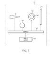
- FIG. 2 is a schematic illustration of the system of FIG. 1 shown in communication with a computer for automated operation of the system in accordance with an exemplary embodiment
- FIG. 3 is a flow chart representing the method of inspecting a structure for a crystallographic imperfection in accordance with an exemplary embodiment
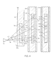
- FIG. 4 is a schematic illustration depicting the results of an inspection of a structure for a crystallographic imperfection in accordance with an exemplary embodiment.
- a system for inspecting structures such as single-crystal superalloy castings in accordance with an exemplary embodiment is shown and generally designated 10.
- the system 10 includes an X-ray source 12, such as an X-ray tube, for emitting arrays 14 of X-rays 16 along a plurality of non-parallel paths 18.
- the system 10 includes a testing area 20 for receiving a structure for inspection.
- the system 10 further includes capture devices 22, 24 that are positioned before and behind the testing area 20 (relative to the source 12) to allow for digital radiography during inspection as discussed below.
- the capture device 22 defines an opening 26 through which the arrays 14 of X-rays 16 pass along their non-parallel paths 18 (three paths are illustrated, though it is understood that arrays 14 of X-rays 16 can be emitted along hundreds of paths).
- the placement of a structure 30, such as a casting, for inspection for a crystallographic imperfection 32 may be discussed.
- the structure 30 is placed in the testing area 20 along the paths 18 at a position 31.
- the position 31 has a measurable location relative to the X-ray source 12 in the direction along the x-axis 34x, the y-axis 34y, and the z-axis 34z.
- the position 31 includes a measurable orientation of the structure 30 about the x-axis 34x, the y-axis 34y, and the z-axis 34z.
- X-rays 16 are directed at the structure 30 for diffraction by the crystallographic imperfection 32 to create diffracted X-rays 36.
- the diffracted X-rays 36 may include back-reflected X-rays 36a that are reflected back from the structure 30 to be captured by the capture device 22.
- These back-reflected X-rays 36a may be analyzed to locate an imperfection 32 on the surface of the structure 30. More specifically, an imperfection 32 on the surface of the structure 30 will diffract the oncoming X-rays 16 differently from the rest of the surface of the structure 30.
- the back-reflected X-rays 36a will create a two-dimensional pattern 38 on the capture device 22. Graphically, the pattern 38 will include lighter areas including fewer X-ray collisions per area and darker areas with more collisions per area.
- the diffracted X-rays 36 may include transmission X-rays 36b that pass through the structure 30 to be captured by the capture device 24. These transmission X-rays 36b allow for the inspection of subsurface or interior imperfections 32 in the structure 30. Similar to the discussion related to surface imperfections 32, a subsurface imperfection 32 in the interior of the structure 30 will diffract the oncoming X-rays 16 differently from the rest of the internal volume of the structure 30. As a result, the transmission X-rays 36b will create a two-dimensional pattern 38 on the capture device 24. Again, the pattern 38 will include lighter areas including fewer X-ray collisions per area and darker areas with more collisions per area.
- a plurality of patterns 38 are captured and compared with one another or otherwise analyzed to locate crystallographic imperfections 32 in the structure 30.
- a pattern 38 is captured for each of a sequence of different positions 31 of the structure 30 relative to the X-ray source 12.
- the position 31 of the structure 30 is directly related to the resulting pattern 38, and the positional data is used in the comparison of patterns 38 to locate the imperfections 32 as is understood in radiography.
- the system 10 is shown to provide for automatic operation and analysis to locate imperfections 32.
- the X-ray source 12 and capture devices 22, 24 are connected to a computer 40.
- the structure 30 is shown to be situated on a mount 42 that is connected to the computer 40.
- the computer 40 is in communication with a marking device 44 and a display device 46.
- the computer 40 is able to place the structure 30 at an initial position 31 and activate the X-ray source 12 to direct X-rays 16 at the structure 30 for a selected exposure time. After the X-rays 16 are diffracted and the diffracted X-rays 36 are captured by the capture device 22, 24, the pattern 38 of diffracted rays 36 is communicated to the computer 40 by the capture device 22, 24. The computer 40 then moves the structure 30 to a new position 31 and repeats the X-ray procedure. The computer 40 may move the structure 30 to a sequence of scripted positions or to a sequence of positions determined based on ongoing analysis of the already-received patterns 38. Because the profile of the X-rays is enhanced and the process is automated, numerous patterns 38 may be captured in a short amount of time.
- the computer 40 may instruct the marking device 44 to mark the imperfection 32 with a target of paint, ink, resin or the like, or the computer 40 may create a three dimensional map of the structure 30 and the location of the imperfection 32 for graphic display, either electronically on the display device 46 a monitor or printed via a non-illustrated printer.
- an X-ray wavelength susceptible to diffraction by a crystallographic imperfection is identified at 50.
- the wavelength may include a single monochromatic X-ray, a band of wavelengths, or a plurality of noncontiguous wavelengths.
- the X-ray source 12 is limited and/or enhanced at 52 to emit arrays 14 having a high fraction of X-rays 16 of the identified wavelength, such as over fifty percent, to produce useable diffraction imaging with a short exposure time. This is done so as to maximize diffraction by any crystallographic imperfection that may be present. By maximizing diffraction, the patterns 38 of diffracted X-rays 36 are amplified so that small imperfections are more easily located.
- the output of the X-ray source 12 may be enhanced by changing the X-ray tube target material, changing the X-ray tube voltage, filtering to remove non-interactive X-ray wavelengths, or through other methods including the use of synchrotrons. Enhancement of the array 14 of X-rays 16 will result in a shortening of the amount of time needed for capturing a proper pattern 38 of diffracted X-rays 36 as well as improved sharpness of the pattern 38.
- the structure 30 is placed at a position 31 relative to the X-ray source 12. Thereafter, the array 14 of X-rays 16 is directed toward the structure 30 along non-parallel paths 18 at 56 for diffraction by an imperfection 32 at 56.
- the diffracted X-rays 36 are captured by the capture device 22, 24 and the pattern 38 of diffracted X-rays 36 is communicated to the computer 50.
- the computer 50 compares or otherwise analyzes the patterns 38 at 60, and determines whether more data (e.g., additional patterns 38) is needed at inquiry 62. If more data is needed, then the computer 50 moves the structure 30 to a new position 31 at 54 and repeats the succeeding steps until the inquiry 62. When more data is not necessary, the location of the crystallographic imperfection 32 is performed at 64 by comparing patterns 38. Specifically, pattern elements such as the presence and position of lighter areas (indicating fewer X-ray collisions) and darker areas (indicating more X-ray collisions) are analyzed in each pattern 38 in view of the associated casting position 31.
- pattern elements such as the presence and position of lighter areas (indicating fewer X-ray collisions) and darker areas (indicating more X-ray collisions) are analyzed in each pattern 38 in view of the associated casting position 31.
- a comparison of these pattern elements for a plurality of patterns 38 indicates what pattern elements are caused by a crystallographic imperfection 32, and the location and physical characteristics of that crystallographic imperfection 32.
- the marking device 44 may mark a target on the imperfection 32 or the structure 30 at 66 and/or create a map of the structure 30 showing the location of the imperfection 32 at 68.
- an X-ray source 112 is configured to emit non-parallel beams such as exemplary beams 114, 115, 116, and 117. Beams 115, 116 and 117 are separated from perpendicular beam 114 by a divergence angle, for example the divergence angle between beams 114 and 117 identified by arrow 118. Further, each beam 114, 115, 116, and 117 is directed at a casting 130 which contains a crystallographic imperfection 132. In FIG.
- the beams are shown passing through the casting 130, and the resulting film 124 produced by a capture device positioned beyond the casting 130, although such beams may be reflected back to capture device position between the casting 130 and the source 112.
- the X-ray source 112 and casting 130 are presented in cross-section view, while the resulting film 124 is illustrated as a top view. Further, while the film 124 includes cross hatching for clarity, in actuality, shading typical of an X-ray capture would be present.
- beam 114 is diffracted from its path 164 to a diffracted path 166 which reaches the capture device 124. Further, beam 115 reaches the capture device 124 along a substantially non-diffracted or slightly diffracted path 168. As paths 166 and 168 intersect the capture device as substantially the same position, the film 124 registers a dark area in a section 125 indicative of the crystallographic imperfection 132. Further, as beam 114 is diffracted off of path 164, the film 125 registers a light area 171 at its intersection with path 164.
- beam 117 is diffracted from path 172 to path 174. Further, beam 116 is substantially non-diffracted or slightly diffracted and remains on path 176. As paths 174 and 176 strike the film 124 at substantially the same position, a dark area 178 is registered by the capture device 124. Further, as beam 117 is diffracted from its path 172, a light area 180 is registered at the intersection of path 172 and the film 124.
- dark areas 170 and light area 171 are caused by wavelength induced diffraction. Where more X-rays reach the film 124, darker areas are created, and where fewer X-rays reach the film 124, lighter areas are registered. This is repeated with dark area 178 and light area 180. Further, dark area 178 and light area 180 also exhibit divergence angle induced diffraction, as beams 116 and 117 were emitted at divergence angles from the perpendicular beam 114.
- the casting 130 may be pivoted to a new position indicated by dotted line 181 which is at a tilt angle of few degrees or more and represented by arrow 182.
- the resulting pattern of dark and light areas is changed.
- the film produced by the capture device is shown with the changed pattern as indicated by numeral 224.
- dark and light areas 170, 171, 178, 180 are moved as a result of tilting the casting 130.
- additional dark areas 184 and light areas 186 may be created, as a result of random satisfaction of Bragg angle and wavelength conditions.
- a combination of wavelength, divergence angle, and tilt angle allows for the analysis of patterns of dark and light areas that indicate the impact or absence of X-ray beams.
- the analysis results in the identification of crystallographic imperfections as well as their location and boundaries.
Landscapes
- Chemical & Material Sciences (AREA)
- Crystallography & Structural Chemistry (AREA)
- Physics & Mathematics (AREA)
- Health & Medical Sciences (AREA)
- Life Sciences & Earth Sciences (AREA)
- Analytical Chemistry (AREA)
- Biochemistry (AREA)
- General Health & Medical Sciences (AREA)
- General Physics & Mathematics (AREA)
- Immunology (AREA)
- Pathology (AREA)
- Analysing Materials By The Use Of Radiation (AREA)
Applications Claiming Priority (1)
| Application Number | Priority Date | Filing Date | Title |
|---|---|---|---|
| US13/169,902 US8605858B2 (en) | 2011-06-27 | 2011-06-27 | Methods and systems for inspecting structures for crystallographic imperfections |
Publications (1)
| Publication Number | Publication Date |
|---|---|
| EP2541237A2 true EP2541237A2 (fr) | 2013-01-02 |
Family
ID=46799985
Family Applications (1)
| Application Number | Title | Priority Date | Filing Date |
|---|---|---|---|
| EP12172657A Withdrawn EP2541237A2 (fr) | 2011-06-27 | 2012-06-19 | Procédés et systèmes permettant d'inspecter des structures d'imperfections cristallographiques |
Country Status (3)
| Country | Link |
|---|---|
| US (1) | US8605858B2 (fr) |
| EP (1) | EP2541237A2 (fr) |
| CN (1) | CN102854205A (fr) |
Cited By (1)
| Publication number | Priority date | Publication date | Assignee | Title |
|---|---|---|---|---|
| EP3545286B1 (fr) * | 2016-11-28 | 2023-11-08 | Safran | Procédé de contrôle non destructif d'une pièce de turbomachine |
Families Citing this family (8)
| Publication number | Priority date | Publication date | Assignee | Title |
|---|---|---|---|---|
| US8902428B2 (en) * | 2012-03-15 | 2014-12-02 | Applied Materials, Inc. | Process and apparatus for measuring the crystal fraction of crystalline silicon casted mono wafers |
| KR101414205B1 (ko) | 2013-09-30 | 2014-07-01 | 주식회사 엘지실트론 | 웨이퍼의 기계적 손상 깊이를 측정하는 방법 |
| US9939393B2 (en) | 2015-09-28 | 2018-04-10 | United Technologies Corporation | Detection of crystallographic properties in aerospace components |
| CN109254017B (zh) * | 2017-07-15 | 2021-05-07 | 杭州峙汇科技有限公司 | 树木内部缺陷探测器 |
| CN108254391B (zh) * | 2018-01-29 | 2020-10-16 | 中国工程物理研究院激光聚变研究中心 | 弯曲晶体检测方法及装置 |
| US11341629B2 (en) | 2020-07-02 | 2022-05-24 | Pratt & Whitney Canada Corp. | Systems and methods for generating an inspection image of an object from radiographic imaging |
| GB202014235D0 (en) * | 2020-09-10 | 2020-10-28 | Rolls Royce Plc | System and method of measuring grain orientations |
| CN112762902B (zh) * | 2020-12-24 | 2022-08-23 | 张志高 | 一种市政建设用多功能定点测绘工具 |
Family Cites Families (11)
| Publication number | Priority date | Publication date | Assignee | Title |
|---|---|---|---|---|
| DE3439471A1 (de) | 1984-10-27 | 1986-04-30 | MTU Motoren- und Turbinen-Union München GmbH, 8000 München | Verfahren und vorrichtung zum pruefen einkristalliner gegenstaende |
| JPH05113416A (ja) | 1990-07-23 | 1993-05-07 | Stiftung Deutsche Elektronen Synchrotron Desy | 単結晶材料の異質相の析出を検査する方法 |
| FR2668262B1 (fr) | 1990-10-23 | 1994-04-01 | Centre Nal Recherc Scientifique | Procede d'analyse aux rayons x de pieces monocristallines. |
| GB2288961B (en) | 1994-04-22 | 1998-10-14 | Rolls Royce Plc | An apparatus and a method for inspecting a crystal |
| JP3561738B2 (ja) | 1998-06-02 | 2004-09-02 | 株式会社リガク | Bragg反射自動選出方法および装置並びに結晶方位自動決定方法およびシステム |
| CN1187604C (zh) | 1999-03-16 | 2005-02-02 | 秦内蒂克有限公司 | 分析材料成份的方法和装置 |
| EP1430514A2 (fr) | 2001-09-18 | 2004-06-23 | Koninklijke Philips Electronics N.V. | Procede d'analyse aux rayons x de plaquette en semiconducteur |
| JP3904543B2 (ja) | 2003-10-14 | 2007-04-11 | 株式会社リガク | X線結晶方位測定装置及びx線結晶方位測定方法 |
| WO2008097345A2 (fr) | 2006-08-10 | 2008-08-14 | X-Ray Optical Systems, Inc. | Procédé et système d'imagerie à diffraction de faisceau parallèle large |
| WO2009052464A1 (fr) | 2007-10-18 | 2009-04-23 | U.S.A. As Representated By The Administrator Of The National Aeronautics And Space Administration | Matériaux et dispositifs thermoélectriques |
| US8130908B2 (en) | 2009-02-23 | 2012-03-06 | X-Ray Optical Systems, Inc. | X-ray diffraction apparatus and technique for measuring grain orientation using x-ray focusing optic |
-
2011
- 2011-06-27 US US13/169,902 patent/US8605858B2/en not_active Expired - Fee Related
-
2012
- 2012-06-19 EP EP12172657A patent/EP2541237A2/fr not_active Withdrawn
- 2012-06-26 CN CN2012102690144A patent/CN102854205A/zh active Pending
Non-Patent Citations (1)
| Title |
|---|
| None |
Cited By (1)
| Publication number | Priority date | Publication date | Assignee | Title |
|---|---|---|---|---|
| EP3545286B1 (fr) * | 2016-11-28 | 2023-11-08 | Safran | Procédé de contrôle non destructif d'une pièce de turbomachine |
Also Published As
| Publication number | Publication date |
|---|---|
| US20120328079A1 (en) | 2012-12-27 |
| CN102854205A (zh) | 2013-01-02 |
| US8605858B2 (en) | 2013-12-10 |
Similar Documents
| Publication | Publication Date | Title |
|---|---|---|
| US8605858B2 (en) | Methods and systems for inspecting structures for crystallographic imperfections | |
| EP3190402B1 (fr) | Dispositif de traitement de mesure, appareil d'inspection par rayons x, procédé de fabrication d'une structure, procédé de traitement de mesure et programme de traitement de mesure | |
| EP1777491B1 (fr) | Procédé et dispositif pour inspecter un objet | |
| EP2226609A2 (fr) | Détection non destructive de certain anomalies (corps étrangers, dimensions anomals) d'un engin par example au moyens de tomodensitométrie | |
| TWI484158B (zh) | 基板檢查系統 | |
| US20240036221A1 (en) | Setting method, inspection method, defect evaluation device and structure manufacturing method | |
| CA2829575C (fr) | Systeme d'inspection reposant sur un protocole | |
| JP2014528794A (ja) | ガスタービンを検査するための内視鏡検査システムおよび対応する方法 | |
| US9964399B2 (en) | Non-destructive mapping of surface condition to evaluate wear conditions | |
| JP2010261933A (ja) | 非破壊検査方法及びシステム | |
| US20140232857A1 (en) | Three-dimensional surface inspection system using two-dimensional images and method | |
| JP2013072788A (ja) | 基板表面欠陥検査方法および検査装置 | |
| US9222900B2 (en) | X-ray diffraction method of mapping grain structures in a crystalline material sample, and an X-ray diffraction apparatus | |
| JP2000507700A (ja) | X線回折を用いて表面下結晶構造を検知するための装置及び方法 | |
| Du Plessis | X‐ray tomography for the advancement of laser powder bed fusion additive manufacturing | |
| EP2775295B1 (fr) | Procédé de mise en correspondance de structures de grain par diffraction des rayons X dans un échantillon de matériau cristallin et appareil de diffraction des rayons X | |
| CN110192103A (zh) | 用于非破坏性控制涡轮发动机部件的方法 | |
| JP3971943B2 (ja) | 光学的検査方法及び光学的検査システム | |
| EP3351928A1 (fr) | Inspection de stratifiés à diffusion latérale de rayons x | |
| JP2007285973A (ja) | ダイカスト部品の自動欠陥検査装置 | |
| US20240070968A1 (en) | System and method of producing a computer-generated image of a component part using computed tomography | |
| US8831172B2 (en) | Method for filmless radiographic inspection of components | |
| JP4719836B2 (ja) | X線回折法によるNi基超合金の劣化診断法および余寿命評価法 | |
| JP4434116B2 (ja) | 金属箔張り積層板の検査方法 | |
| EP4155718B1 (fr) | Porosité d'une pièce |
Legal Events
| Date | Code | Title | Description |
|---|---|---|---|
| PUAI | Public reference made under article 153(3) epc to a published international application that has entered the european phase |
Free format text: ORIGINAL CODE: 0009012 |
|
| 17P | Request for examination filed |
Effective date: 20120619 |
|
| AK | Designated contracting states |
Kind code of ref document: A2 Designated state(s): AL AT BE BG CH CY CZ DE DK EE ES FI FR GB GR HR HU IE IS IT LI LT LU LV MC MK MT NL NO PL PT RO RS SE SI SK SM TR |
|
| AX | Request for extension of the european patent |
Extension state: BA ME |
|
| STAA | Information on the status of an ep patent application or granted ep patent |
Free format text: STATUS: THE APPLICATION HAS BEEN WITHDRAWN |
|
| 18W | Application withdrawn |
Effective date: 20130516 |