EP2541073B1 - Pneumatikzylinder mit selbstjustierender Endlagendämpfung - Google Patents
Pneumatikzylinder mit selbstjustierender Endlagendämpfung Download PDFInfo
- Publication number
- EP2541073B1 EP2541073B1 EP12171413.3A EP12171413A EP2541073B1 EP 2541073 B1 EP2541073 B1 EP 2541073B1 EP 12171413 A EP12171413 A EP 12171413A EP 2541073 B1 EP2541073 B1 EP 2541073B1
- Authority
- EP
- European Patent Office
- Prior art keywords
- damping
- chamber
- control valve
- pressure
- control
- Prior art date
- Legal status (The legal status is an assumption and is not a legal conclusion. Google has not performed a legal analysis and makes no representation as to the accuracy of the status listed.)
- Active
Links
Images



Classifications
-
- F—MECHANICAL ENGINEERING; LIGHTING; HEATING; WEAPONS; BLASTING
- F15—FLUID-PRESSURE ACTUATORS; HYDRAULICS OR PNEUMATICS IN GENERAL
- F15B—SYSTEMS ACTING BY MEANS OF FLUIDS IN GENERAL; FLUID-PRESSURE ACTUATORS, e.g. SERVOMOTORS; DETAILS OF FLUID-PRESSURE SYSTEMS, NOT OTHERWISE PROVIDED FOR
- F15B15/00—Fluid-actuated devices for displacing a member from one position to another; Gearing associated therewith
- F15B15/20—Other details, e.g. assembly with regulating devices
- F15B15/22—Other details, e.g. assembly with regulating devices for accelerating or decelerating the stroke
- F15B15/222—Other details, e.g. assembly with regulating devices for accelerating or decelerating the stroke having a piston with a piston extension or piston recess which throttles the main fluid outlet as the piston approaches its end position
-
- F—MECHANICAL ENGINEERING; LIGHTING; HEATING; WEAPONS; BLASTING
- F15—FLUID-PRESSURE ACTUATORS; HYDRAULICS OR PNEUMATICS IN GENERAL
- F15B—SYSTEMS ACTING BY MEANS OF FLUIDS IN GENERAL; FLUID-PRESSURE ACTUATORS, e.g. SERVOMOTORS; DETAILS OF FLUID-PRESSURE SYSTEMS, NOT OTHERWISE PROVIDED FOR
- F15B15/00—Fluid-actuated devices for displacing a member from one position to another; Gearing associated therewith
- F15B15/20—Other details, e.g. assembly with regulating devices
- F15B15/204—Control means for piston speed or actuating force without external control, e.g. control valve inside the piston
Definitions
- the invention relates to a pneumatic cylinder with a cylinder housing and a cylinder piston reciprocating therein under the action of pressure, each of which is subjected to a working pressure in its one direction of movement via a connecting line acting alternately as a pressure line and ventilation line, and on its opposite side in the cylinder interior with a Lower ventilation pressure displaces air from the cylinder interior, at least at one end of the cylinder piston path a damping arrangement is arranged with a damping chamber arranged in the cylinder interior and limited by the moving cylinder piston, which is controlled via a ventilation path with a control valve connected therein to damp the end position of the cylinder piston , wherein the pneumatically controlled control valve comprises a control piston, the control side facing away from the ventilation path from a control chamber the pneumatic pressure is applied.
- a provided with an end position damping for its cylinder piston pneumatic cylinder with the aforementioned features is from the EP 1 998 054 A2 known.
- a damping pin which extends axially into the cylinder housing and onto which the cylinder piston movable back and forth in the cylinder housing with a recess formed therein runs up.
- a connecting line for the cylinder interior extends through the damping pin, by means of which compressed air can either be supplied at a working pressure in order to cause the movement of the cylinder piston away from the damping pin, or via the movement of the cylinder piston on the damping pin to those from the cylinder interior displaced air is discharged.
- the damping phase begins EP 1 998 054 A2 Described embodiment of the damping space is formed by the annular space surrounding the damping pin.
- the damping chamber is connected to the connecting line by means of a ventilation duct that forms a ventilation path.
- a pneumatically controlled control valve with a control piston which is movable in its displacement and is acted upon on its control side by the working pressure acting on the cylinder piston is switched into the ventilation duct. It is thus achieved that at the point in time at which the pressure present in the damping chamber and increasing with increasing displacement of the cylinder piston into the damping chamber exceeds the prevailing working pressure, the control valve releases the ventilation duct, so that the air present in the damping chamber can flow out in a controlled manner and one End position damping for the cylinder piston is effected.
- the known end position damping has the disadvantage that the beginning of the venting of the damping space is determined by the working pressure applied in each case, i.e.
- the damping space is only vented when the pressure in the damping space or rising therein is or becomes greater than the working pressure. This means that only a small energy range is available for performing the damping. It should be taken into account that during the movement of the cylinder piston in the direction of the damping pin, a pressure release has already taken place in the damping chamber, since during this movement of the cylinder piston the air displaced from the cylinder interior is discharged via the associated connecting line. In this respect, there is only a significantly lower ventilation pressure in the damping room.
- the invention is therefore based on the object of improving the damping behavior in the case of a pneumatic cylinder with the generic features in the end position damping.
- the basic idea of the invention provides that the control chamber of the control valve is connected by means of a line connection to a region of the damping arrangement which is under ventilation pressure, and in the line connection a closing arrangement with a controlled one Closing element is switched on, by means of which the currently existing venting pressure in the control chamber can be included in the control chamber of the control valve at the beginning of the damping characterized by a pressure increase in the damping chamber and acts as a fixed control pressure on the control piston of the control valve and determines the opening time of the control valve to release the venting path.
- the invention is thus based on the advantageous principle that the pressure present at the beginning of the damping in the damping space, which is generally lower than the working pressure, is used as a threshold for the start of damping with a discharge of the air still present in the damping space, by this the pressure currently present at the beginning of the damping in the damping space or in the connecting line is used to control the control valve which releases the venting path for the damping space.
- the venting-side pressure is thus defined as the control pressure for the control valve via the line connection created between the control chamber of the control valve and the area of the damping arrangement that is under venting pressure, and this line connection is interrupted by the controlled movement of the closing element at the start of damping and thus the control pressure for the Control valve fixed.
- the mode of operation of the end position damping is independent of the driving style of the pneumatic cylinder, whether with fast or slow piston travel, since, according to the invention, the only thing that matters is the pressure on the venting side at the time the damping begins.
- the energy range or working range of the damping device according to the invention is significantly expanded.
- the controlled movement of the closing element can take place in different ways according to embodiments of the invention. First of all, it can be provided that the movement of the closing element is electrically controlled as a function of a control signal picked up at the start of damping. Here, the pressure increase in the damping chamber is recorded separately, and upon a corresponding signal, the closing element is brought into a position in which it closes the control chamber of the control valve.
- the movement of the closing element is controlled mechanically by the relative movement of the cylinder piston to the cylinder housing.
- a pin that mechanically acts on the closing element and moves it into its closed position with respect to the control chamber of the control valve can be arranged such that when the cylinder piston reaches a position in which damping is to begin, the pin comes into contact with the closing element and this one further movement of the cylinder piston moves.
- the movement of the closing element of the closing arrangement into its closed position closing the control chamber of the control valve is pneumatically controlled by the pressure rising in the damping chamber when the damping begins.
- the closing element is designed as a piston element that is longitudinally movable in a displacement, the pressure present in the damping chamber being applied to the pressure side of the closing element facing away from the direction of the closing movement and the pressure chamber lying on the opposite side of the closing element is connected to the control chamber of the control valve.
- the piston element can be designed as a solid piston or as a membrane.
- control valve and closing arrangement are arranged in the cylinder cover of the pneumatic cylinder.
- the line connection between the control chamber of the control valve and the region of the damping arrangement which has the venting pressure is formed by a connecting channel running between the pressure chamber of the closing arrangement connected to the control chamber and the connecting line and that the vent path from one of the damping space outgoing and over the pressure side displacement of the locking arrangement and via the control valve to the connecting line extending ventilation channel, which is blocked by the locking arrangement against the damping chamber before the start of damping.
- both the line connection to the control chamber of the control valve and the venting path are each connected to the connection line.
- a check valve with a passage direction directed from the control valve to the connection line can be switched on in the section of the ventilation path running between the control valve and the connection line.
- the line connection between the control chamber of the control valve and the damping chamber having the venting pressure before the beginning of damping is formed by a connecting channel receiving the locking arrangement, and that the venting path is made from a starting point from the damping chamber and via the control valve to the connecting line extending ventilation duct.
- the venting path is in turn connected to the connection bore, while the line connection for introducing the pressure present at the beginning of the damping into the control chamber of the control valve is now connected to the damping chamber.
- control valve and closing arrangement are arranged in the cylinder piston of the pneumatic cylinder.
- the same arrangement of control valve and closing arrangement and the same conduit paths can again be carried out as described for the above exemplary embodiment.
- the line connection between the control chamber of the control valve and the region of the damping arrangement which has the ventilation pressure is formed by a connecting channel running between the pressure chamber of the closing arrangement connected to the control chamber and the recess of the cylinder piston, and that the ventilation path is made from one of the damping chamber outgoing and over the pressure side displacement of the locking arrangement and via the control valve into the recess of the cylinder piston extending ventilation channel, which is blocked by the locking arrangement against the damping chamber before the start of damping.
- the line connection between the control chamber of the control valve and the damping chamber having the venting pressure before the start of damping is formed by a connecting channel receiving the locking arrangement, and that the venting path runs from a starting from the damping chamber and via the control valve to the recess in the cylinder piston Vent channel exists.
- control piston of the control valve is arranged in the valve housing of the control valve without a seal with respect to the ventilation path.
- This enables the damping chamber to be vented with a limited or small flow cross-section via the control valve, which is particularly important in cases in which, as a result of a very slow movement of the cylinder piston, there are only very small pressure differences between those in the damping chamber from the start of damping damping pressure and the initial final ventilation pressure fixed as the control pressure for the control piston of the control valve, so that the control piston is not moved into its position which frees the cross-section of the end ventilation duct guided via the control valve,
- control piston of the control valve and the closing element of the closing arrangement are each held in a defined starting position by associated spring arrangements before the start of damping.
- a defined starting position of the control piston and closing element can also be achieved in alternative embodiments by switching on control elements, such as check valves or the like, in the corresponding flow paths, or by adjusting the corresponding area ratios or by using differential pistons or membranes.
- control piston of the control valve and the closing element of the closing arrangement are each pressure-balanced by arranging additional line connections before the start of damping.
- FIG EP 1 998 054 A2 The basic structure of a pneumatic cylinder 10 with end position damping is shown in FIG EP 1 998 054 A2 described.
- a cylinder piston 13 In a cylinder housing 11 closed on both sides by cylinder cover 12, a cylinder piston 13 is movably guided to and fro as a carrier of mass m. For its movement to the left in the direction of arrow 14, compressed air at working pressure is introduced into the cylinder interior 16 via a connecting line 15 passing through the right cylinder cover 12.
- End position damping for the cylinder piston 13 is formed on the opposite side of the cylinder.
- a damping pin 17 protruding in the axial direction from the cylinder cover 12 into the cylinder interior 16 is formed, onto which the cylinder piston 13 moves with a recess 18 formed in it.
- a connection bore 19 extending through the damping pin 17 is provided. It is the case that to move the cylinder piston 13 in the direction of arrow 14, the left part of the cylinder interior 16 must be relieved of pressure so that the air displaced therefrom by the movement of the cylinder piston 13 can flow out via the connecting line 19. Thus, during the movement of the cylinder piston 13 in the direction of the arrow 14 in the left part of the cylinder interior, there is a venting pressure that is below the working pressure lies.
- FIG Figure 2 A first exemplary embodiment for such a ventilation path, including end position damping for the movement of the cylinder piston 13, is shown in FIG Figure 2 shown, in which the components of the end position damping in the Figure 1 apparent left cylinder cover 12 are arranged.
- a control valve 21 is arranged in the cylinder cover 12, in the piston chamber 22 of which a control piston 23 is arranged displaceably.
- the control piston On one side, the control piston has a shoulder 24 as an end stop for its movement in the piston chamber 22.
- a control chamber 25 On the opposite side of the control piston 23, a control chamber 25 is arranged as part of the piston chamber 22, which is discussed below.
- a closing arrangement 26 is formed in the cylinder cover 12, with a closing element 28 which is arranged displaceably in a displacement 27.
- a pressure chamber 29 is formed, which on the one hand has a line connection 30 to the connecting line 19 formed in the damping pin 17 connected.
- the pressure chamber 29 is also connected to the by means of a connecting bore 31 Control chamber 25 of the control valve 21 connected, wherein this connecting bore 31 can be closed in a corresponding position of the closing element 28 by means of a closing projection 32 formed on the closing element 28 and a sealing region 33 formed thereon.
- control piston 23 of the control valve 21 is biased by means of a spring 34 arranged in the control chamber 25, wherein in its neutral position the control piston 23 is biased by the spring 34 into its end position with a stop of the shoulder 24 against the wall of the piston chamber 22 is.
- the closing element 28 is also biased into its closed position, which is still to be explained, by means of a spring 35 arranged in the pressure chamber 29 of the closing arrangement 26, in which the closing extension 32 of the closing element 28 releases the connecting bore 31 between the pressure chamber 29 and the control chamber 25 of the control valve 21.
- a ventilation duct consisting of three sections 36a, b, c is formed in the cylinder cover 12.
- the first section 36a leads from the damping space 20 into the displacement 27 of the closing arrangement 26, the closing element 28 in the starting position closing the displacement 27 against the first section 36a of the ventilation duct with a sealing region 38 formed on it due to the pretension of the spring 35.
- a second section 36b of the ventilation duct then leads from the displacement 27 to the ventilation space 37 of the control valve 21 arranged opposite the control chamber 25 in such a way that the outlet of the second section 36b from the displacement 27 of the locking arrangement 26 can be released from the locking element 28 in its displaced position.
- a third section 36c of the ventilation channel leads from the ventilation space 37 of the control valve 21 to the connecting line 19 in the damping pin 17 such that in the initial position the outlet of the third section 36c of the Vent channel from the vent space 37 covered by the control piston 23, but can be released by this in the displaced position.
- the venting pressure below the working pressure is initially via the line connection 30 in the pressure chamber 29 of the locking arrangement 26 and via the between the Pressure chamber 29 and the control chamber 25 of the control valve 21 existing connection bore 31 also in the control chamber 25 of the control valve 21.
- the ventilation pressure present in the pressure chamber 29 as well as in the control chamber 25 initially ensures that the closing element 28 is supported in a pressure-balanced manner because the ventilation pressure is also present on the closing side of the closing arrangement 26 defined by the sealing region 38 of the closing element 28 via the first section 36a of the ventilation channel .
- the spring 35 ensures the closed position of the closing element 28 with respect to the first section 36a of the ventilation channel.
- a deliberately missing seal of the control piston 23 against the third section 36c of the venting channel ensures that the venting pressure in the third section 36c of the venting channel connected to the connecting line 19 is also present Venting space 37 of the control valve is present, the control piston 23 being held in the defined starting position by the spring 34 acting on it.
- damping pressure in the damping space 20 increases.
- the start of damping is characterized by this increase in pressure.
- the venting pressure still present in the system at the moment the damping begins is present in particular in the control chamber 25 of the control valve 21 and also in the pressure chamber 29 of the closing arrangement 26.
- the pressure rising in the damping chamber 20 from the start of damping now leads via the first section 36a of the venting channel to pressurizing the closing element 28, so that the closing element is moved into its closed position, in which its closing extension 32 with sealing area 33 connects the connecting bore 31 to the control chamber 25
- Control valve 21 closes.
- the ventilation pressure present in the control chamber 25 at the time of the pressure increase in the damping chamber 20 is fixed as the control pressure for the control piston 23.
- the closing movement of the closing element 28 releases the second section 36b of the ventilation channel leading away from the displacement 27 of the closing arrangement 26, so that the air displaced with increasing pressure from the damping chamber 20 via the sections 36a, b of the ventilation channel into the ventilation chamber 37 of the control valve 21 occurs and also causes a pressure increase here. If this damping pressure present in the ventilation space 37, due to the increasing pressure in the damping space 20, exceeds the ventilation pressure enclosed in the control chamber 25 of the control valve 21, the control piston 23 is displaced into the control chamber 25 and thereby gives the third section 36c of the ventilation chamber 37 Vent channel free, so that the air displaced from the damping space 20 can flow out via the now released sections 36a, b, c of the vent channel into the connecting line 19. So is a pressure controlled and thus damping discharge of the air displaced from the damping space 20.
- the arrangement of the spring 34 biasing the control piston 23 can be dispensed with, for example, when a check valve with a passage direction directed from the control valve 21 to the connecting line 19 is switched on in the third section 36c of the ventilation duct.
- a check valve with a passage direction directed from the control valve 21 to the connecting line 19 is switched on in the third section 36c of the ventilation duct.
- the illustrated embodiment differs from the previously described embodiment in that the control valve 21 and the locking arrangement 26 are arranged in the cylinder cover 12 in a modified manner, and in that the line connection 30 is connected directly to the damping space 20 between the pressure chamber 29 of the locking arrangement 26 and thus also the control chamber 25 of the control valve 21 In this case, the ventilation duct is no longer guided over the closing arrangement, rather only a section 36a of the ventilation duct leading from the damping chamber 20 to the ventilation chamber 37 of the control valve 21 and a section 36c of the damping duct leading from the ventilation chamber 37 to the connecting line 19 are provided.
- the locking arrangement 26 arranged in the cylinder cover 12 is connected to the damping space 20 via a feed line 50.
- the closing element 28 is guided in the displacement 27 of the closing arrangement 26 in a non-sealed manner so that the air present in the damping space 20 can first flow past the closing element 28 into a line section 45 connected to the control chamber 25 of the control valve 21.
- the closed position of the closing element 28 at the end of the control chamber 25 against the damping chamber 20 is due to a sealing seat 46 between the displacement 27 of the locking arrangement 26 and the line section 45 formed, on which the closing element 28 is seated in its closed position with the sealing region 38a formed on it.
- the line section 45 is connected to the section 36c of the venting channel, whereby in the area of the line section 45 between the section 36c of the venting channel and the connection of the control chamber 25 of the control valve 21, a pressure piston 48 connected to the closing element 28 via a rod 47 seals is guided, which in turn is biased by a spring 35a into a position of the closing element 28, in which the closing element 28 is lifted from the sealing seat 46 and thus releases the flow path from the damping chamber 20 into the control chamber 25 of the control valve 21.
- the venting pressure in the damping chamber 20 at the beginning of the damping (arrow 40) is present on the one hand via the section 36a of the venting channel in the venting chamber 37 of the control valve 21.
- This venting pressure is also present via the feed line 50 and the open flow path in the closing arrangement 26, also in the displacement 27 of the closing arrangement 26, the line section 45 and also in the control chamber 25 of the control valve 21, so that both the control piston 23 and the closing element 28 are arranged in a pressure-balanced manner are.
- Control pistons 23 and closing element 28 are each held in a defined starting position by means of the corresponding springs 34 and 35a.
- the closing element 28 is again moved in contact with its sealing region 38a on the sealing seat 46. so that the ventilation pressure present in the control chamber 25 of the control valve 21 at the time of the start of damping is enclosed in the control chamber 25 and acts here as a fixed control pressure for the control piston 23.
- the pressure rising in the damping chamber 20 is also present in the ventilation chamber 37 of the control valve 21 via the section 36a of the ventilation channel, and as soon as the damping pressure exceeds the control pressure of the control valve 21 characterized by the ventilation pressure, the control piston 23 is moved into its position in which it Connection of section 36c of the ventilation channel is released, so that the air present in the damping space 20 can flow out into the connecting line 19 via the ventilation path 36a, 36c.
Landscapes
- Engineering & Computer Science (AREA)
- Physics & Mathematics (AREA)
- Fluid Mechanics (AREA)
- Mechanical Engineering (AREA)
- General Engineering & Computer Science (AREA)
- Fluid-Damping Devices (AREA)
- Fluid-Pressure Circuits (AREA)
Description
- Die Erfindung betrifft einen Pneumatikzylinder mit einem Zylindergehäuse und einem darin unter Druckeinwirkung hin und her gehenden Zylinderkolben, der jeweils in seiner einen Bewegungsrichtung über eine wechselweise als Druckleitung und Entlüftungsleitung wirkende Anschlussleitung mit einem Arbeitsdruck beaufschlagt ist und auf seiner jeweils gegenüberliegenden Seite die im Zylinderinnenraum mit einem geringeren Entlüftungsdruck anstehende Luft aus dem Zylinderinnenraum verdrängt, wobei an zumindest einem Ende des Zylinderkolbenweges eine Dämpfungsanordnung mit einem im Zylinderinnenraum angeordneten und von dem sich bewegenden Zylinderkolben begrenzten Dämpfungsraum angeordnet ist, welcher zur Endlagendämpfung des Zylinderkolbens über einen Entlüftungsweg mit einem darin eingeschalteten Steuerventil gesteuert entlüftet wird, wobei das pneumatisch gesteuerte Steuerventil einen Steuerkolben umfasst, dessen dem Entlüftungsweg abgewandte Steuerseite von einem in einem Steuerraum anstehenden pneumatischen Druck beaufschlagt ist.
- Ein mit einer Endlagendämpfung für seinen Zylinderkolben versehener Pneumatikzylinder mit den vorgenannten Merkmalen ist aus der
EP 1 998 054 A2 bekannt. Hierbei ist in einem durch einen Zylinderdeckel abgeschlossenen Endbereich des Zylindergehäuses bei einem vorzugsweise kolbenstangenlosen Pneumatikzylinder ein sich axial in das Zylindergehäuse erstreckender Dämpfzapfen vorgesehen, auf den der im Zylindergehäuse hin und her bewegliche Zylinderkolben mit einer in ihm ausgebildeten Ausnehmung aufläuft. Durch den Dämpfzapfen erstreckt sich eine Anschlussleitung für den Zylinderinnenraum, mittels der entweder Druckluft mit einem Arbeitsdruck zugeführt werden kann, um die Bewegung des Zylinderkolbens von dem Dämpfzapfen weg zu bewirken, oder über die bei der Bewegung des Zylinderkolbens auf den Dämpfzapfen zu die aus dem Zylinderinnenraum verdrängte Luft abgeleitet wird. Im Augenblick des Auflaufens des Zylinderkolbens auf den Dämpfzapfen beginnt die Dämpfungsphase, wobei bei der in derEP 1 998 054 A2 beschriebenen Ausgestaltung der Dämpfungsraum von dem den Dämpfzapfen umschließenden Ringraum gebildet ist. Um die im Dämpfungsraum nach Beginn der Dämpfungsphase eingeschlossene Luft gezielt abzuleiten, ist der Dämpfungsraum mittels eines einen Entlüftungsweg ausbildenden Entlüftungskanals mit der Anschlussleitung verbunden. In den Entlüftungskanal ist ein pneumatisch gesteuertes Steuerventil mit einem in seinem Hubraum beweglichen Steuerkolben eingeschaltet, der auf seiner Steuerseite jeweils von dem auf den Zylinderkolben einwirkenden Arbeitsdruck beaufschlagt ist. Damit wird erreicht, dass in dem Zeitpunkt, in welchem der im Dämpfungsraum anstehende und mit zunehmendem Weg des Zylinderkolbens in den Dämpfungsraum hinein ansteigende Druck den anliegenden Arbeitsdruck übersteigt, das Steuerventil den Entlüftungskanal freigibt, so dass die im Dämpfungsraum anstehende Luft gesteuert abströmen kann und eine Endlagendämpfung für den Zylinderkolben bewirkt ist. - Mit der bekannten Endlagendämpfung ist der Nachteil verbunden, dass der Beginn der Entlüftung des Dämpfungsraumes durch den jeweils anliegenden Arbeitsdruck festgelegt ist, d.h. eine Entlüftung des Dämpfungsraums findet nur dann statt, wenn der im Dämpfungsraum anstehende bzw. darin ansteigende Druck größer ist bzw. wird als der Arbeitsdruck. Damit steht nur ein geringer Energiebereich für die Durchführung der Dämpfung zur Verfügung. Es ist dabei zu berücksichtigen, dass während der Bewegung des Zylinderkolbens in Richtung des Dämpfzapfens im Dämpfungsraum bereits eine Druckentspannung stattgefunden hat, da bei dieser Bewegung des Zylinderkolbens die aus dem Zylinderinnenraum verdrängte Luft über die zugehörige Anschlussleitung abgeführt wird. Insofern steht im Dämpfungsraum nur noch ein wesentlich geringerer Entlüftungsdruck an. Insbesondere bei entsprechend hohen Arbeitsdrücken oder beispielsweise aufgrund langsamer Fahrt des Zylinderkolbens im Dämpfungsraum nur allmählich ansteigendem Druck braucht es somit lange, bis ein den Arbeitsdruck übersteigender Druck im Dämpfungsraum erreicht ist, und daher reicht das Dämpfungsverhalten der bekannten Dämpfungsanordnung nicht aus.
- Der Erfindung liegt daher die Aufgabe zugrunde, bei einem Pneumatikzylinder mit den gattungsgemäßen Merkmalen dessen Dämpfungsverhalten bei der Endlagendämpfung zu verbessern.
- Die Lösung dieser Aufgabe ergibt sich einschließlich vorteilhafter Ausgestaltungen und Weiterbildungen der Erfindung aus dem Inhalt der Patentansprüche, welche dieser Beschreibung nachgestellt sind.
- Die Erfindung sieht in ihrem Grundgedanken vor, dass der Steuerraum des Steuerventils mittels einer Leitungsverbindung mit einem unter Entlüftungsdruck stehenden Bereich der Dämpfungsanordnung verbunden und in die Leitungsverbindung eine Schließanordnung mit einem gesteuerten Schließelement eingeschaltet ist, mittels dessen der im Steuerraum des Steuerventils bei dem durch einen Druckanstieg im Dämpfungsraum charakterisierten Dämpfungsbeginn jeweils aktuell anstehende Entlüftungsdruck im Steuerraum einschließbar ist und als dergestalt fixierter Steuerdruck auf den Steuerkolben des Steuerventils wirkt und den Öffnungszeitpunkt des Steuerventils zur Freigabe des Entlüftungsweges festlegt.
- Die Erfindung beruht somit auf dem vorteilhaften Prinzip, dass der jeweilig bei Dämpfungsbeginn im Dämpfungsraum anstehende Druck, der in der Regel geringer als der Arbeitsdruck ist, als Schwelle für den Beginn der Dämpfung mit einer Ableitung der noch im Dämpfungsraum anstehenden Luft herangezogen wird, indem dieser jeweils aktuell bei Dämpfungsbeginn im Dämpfungsraum bzw. in der Anschlussleitung vorhandene Druck zur Steuerung des den Entlüftungsweg für den Dämpfungsraum freigebenden Steuerventils herangezogen ist. Erfindungsgemäß wird demnach der entlüftungsseitige Druck über die zwischen dem Steuerraum des Steuerventils und dem unter Entlüftungsdruck stehenden Bereich der Dämpfungsanordnung geschaffene Leitungsverbindung als Steuerdruck für das Steuerventil festgelegt, und es wird diese Leitungsverbindung durch die gesteuerte Bewegung des Schließelements bei Dämpfungsbeginn unterbrochen und damit der Steuerdruck für das Steuerventil fixiert. Insoweit ist die Arbeitsweise der Endlagendämpfung unabhängig von der Fahrweise des Pneumatikzylinders, ob mit schneller oder mit langsamer Kolbenfahrt, da es gemäß der Erfindung ausschließlich auf den zum Zeitpunkt des Dämpfungsbeginns entlüftungsseitig anstehenden Druck ankommt. Dadurch wird der Energiebereich bzw. Arbeitsbereich der erfindungsgemäßen Dämpfungseinrichtung deutlich erweitert.
- Die gesteuerte Bewegung des Schließelements kann nach Ausführungsbeispielen der Erfindung in unterschiedlicher Weise erfolgen. Zunächst kann vorgesehen sein, dass die Bewegung des Schließelements in Abhängigkeit von einem bei Dämpfungsbeginn abgegriffenen Steuersignal elektrisch gesteuert ist. Hierbei wird der Druckanstieg im Dämpfungsraum gesondert erfasst, und auf ein entsprechendes Signal hin wird das Schließelement in eine Stellung verbracht, in der es den Steuerraum des Steuerventils abschließt.
- In einer alternativen Ausführungsform der Erfindung kann vorgesehen sein, dass die Bewegung des Schließelements mechanisch durch die Relativbewegung des Zylinderkolbens zum Zylindergehäuse gesteuert ist. Hierzu kann beispielsweise ein das Schließelement mechanisch beaufschlagender und in seine Schließstellung bezüglich des Steuerraums des Steuerventils verschiebender Stift derart angeordnet sein, dass bei Erreichen einer Stellung des Zylinderkolbens, bei der der Dämpfungsbeginn erfolgen soll, der Stift in Kontakt mit dem Schließelement kommt und dieses bei einer weiteren Bewegung des Zylinderkolbens verschiebt.
- Gemäß einer bevorzugten Ausführungsform ist vorgesehen, dass die Bewegung des Schließelements der Schließanordnung in seine den Steuerraum des Steuerventils abschließende Schließstellung pneumatisch durch den im Dämpfungsraum bei Dämpfungsbeginn ansteigenden Druck gesteuert ist. Hiermit ist der Vorteil verbunden, dass keine zusätzlichen Bauteile oder Regelungen vorzusehen sind, so dass die Steuerung der Endlagendämpfung ausschließlich durch die zum Zeitpunkt des Dämpfungsbeginns herrschenden Druckverhältnisse erfolgt.
- Hierzu kann nach einem Ausführungsbeispiel der Erfindung vorgesehen sein, dass das Schließelement als in einem Hubraum längsbewegliches Kolbenelement ausgebildet ist, wobei an der der Richtung der Schließbewegung abgewandten Druckseite des Schließelements der im Dämpfungsraum jeweils anstehende Druck anliegt und der auf der gegenüberliegenden Seite des Schließelements liegende Druckraum mit dem Steuerraum des Steuerventils verbunden ist. Das Kolbenelement kann nach Ausführungsbeispielen der Erfindung dabei als massiver Kolben oder auch als eine Membrane ausgebildet sein.
- Die konstruktive Ausbildung einer erfindungsgemäßen und ausschließlich druckgesteuerten Endlagendämpfung lässt sich in bevorzugter Weise bei einer Bauform des Pneumatikzylinders realisieren, wie sie in der gattungsbildenden
EP 1 998 054 A2 beschrieben ist, bei der im Bereich des Endanschlages des Zylinderkolbens ein sich in axialer Richtung in den Zylinderinnenraum erstreckender Dämpfzapfen mit der durch diesen hindurchgeführten Anschlussleitung angeordnet und der Zylinderkolben mit einer den Dämpfzapfen aufnehmenden Ausnehmung ausgeführt ist. - Hierbei kann gemäß einer ersten Ausführungsform der Erfindung vorgesehen sein, dass Steuerventil und Schließanordnung im Zylinderdeckel des Pneumatikzylinders angeordnet sind.
- Bei einer solchen Anordnung der Endlagendämpfung im Zylinderdeckel ist gemäß einem ersten Ausführungsbeispiel der Erfindung vorgesehen, dass die Leitungsverbindung zwischen dem Steuerraum des Steuerventils und dem den Entlüftungsdruck aufweisenden Bereich der Dämpfungsanordnung durch einen zwischen dem mit dem Steuerraum verbundenen Druckraum der Schließanordnung und der Anschlussleitung verlaufenden Verbindungskanal gebildet ist, und dass der Entlüftungsweg aus einem von dem Dämpfungsraum ausgehenden und über den druckseitigen Hubraum der Schließanordnung und über das Steuerventil bis zur Anschlussleitung verlaufenden Entlüftungskanal besteht, der vor Dämpfungsbeginn durch die Schließanordnung gegen den Dämpfungsraum gesperrt ist. In diesem Fall sind sowohl die Leitungsverbindung zum Steuerraum des Steuerventils als auch der Entlüftungsweg jeweils an die Anschlussleitung angeschlossen. Gemäß einer Weiterbildung der Erfindung kann dazu vorgesehen sein, dass in den zwischen dem Steuerventil und der Anschlussleitung verlaufenden Abschnitt des Entlüftungsweges ein Rückschlagventil mit einer vom Steuerventil zur Anschlussleitung gerichteten Durchlassrichtung eingeschaltet ist.
- Gemäß einer alternativen Ausführungsform kann vorgesehen sein, dass die Leitungsverbindung zwischen dem Steuerraum des Steuerventils und dem vor Dämpfungsbeginn den Entlüftungsdruck aufweisenden Dämpfungsraum durch einen die Schließanordnung aufnehmenden Verbindungskanal ausgebildet ist, und dass der Entlüftungsweg aus einem von dem Dämpfungsraum ausgehenden und über das Steuerventil bis zur Anschlussleitung verlaufenden Entlüftungskanal besteht. Hierbei ist der Entlüftungsweg wiederum an die Anschlussbohrung angeschlossen, während die Leitungsverbindung zur Einleitung des bei Dämpfungsbeginn anstehenden Drucks in den Steuerraum des Steuerventils nunmehr an den Dämpfungsraum angeschlossen ist.
- Gemäß einer weiteren Ausführungsform der Erfindung kann vorgesehen sein, dass Steuerventil und Schließanordnung im Zylinderkolben des Pneumatikzylinders angeordnet sind. Bei dieser Ausführungsform können wiederum die gleiche Anordnung von Steuerventil und Schließanordnung und die gleichen Leitungswege vorgenommen sein, wie zu dem vorstehenden Ausführungsbeispiel beschrieben.
- Im Einzelnen kann vorgesehen sein, dass die Leitungsverbindung zwischen dem Steuerraum des Steuerventils und dem den Entlüftungsdruck aufweisenden Bereich der Dämpfungsanordnung durch einen zwischen dem mit dem Steuerraum verbundenen Druckraum der Schließanordnung und der Ausnehmung des Zylinderkolbens verlaufenden Verbindungskanal ausgebildet ist, und dass der Entlüftungsweg aus einem von dem Dämpfungsraum ausgehenden und über den druckseitigen Hubraum der Schließanordnung und über das Steuerventil bis in die Ausnehmung des Zylinderkolbens verlaufenden Entlüftungskanal besteht, der vor Dämpfungsbeginn durch die Schließanordnung gegen den Dämpfungsraum gesperrt ist.
- Alternativ kann vorgesehen dass, die die Leitungsverbindung zwischen dem Steuerraum des Steuerventils und dem vor Dämpfungsbeginn den Entlüftungsdruck aufweisenden Dämpfungsraum durch einen die Schließanordnung aufnehmenden Verbindungskanal ausgebildet ist, und dass der Entlüftungsweg aus einem von dem Dämpfungsraum ausgehenden und über das Steuerventil bis zur Ausnehmung des Zylinderkolbens verlaufenden Entlüftungskanal besteht.
- In Weiterbildungen der Erfindung kann vorgesehen sein, dass der Steuerkolben des Steuerventils ohne eine Abdichtung gegenüber dem Entlüftungsweg im Ventilgehäuse des Steuerventils angeordnet ist. Hierdurch wird eine Entlüftung des Dämpfungsraumes mit einem begrenzten bzw. geringen Strömungsquerschnitt über das Steuerventil ermöglicht, die insbesondere in den Fällen zum Tragen kommt, in denen es in Folge einer sehr langsamen Bewegung des Zylinderkolbens nur zu sehr geringen Druckunterschieden zwischen dem ab dem Dämpfungsbeginn im Dämpfungsraum anstehenden Dämpfungsdruck und dem als Steuerdruck für den Steuerkolben des Steuerventils fixierten anfänglichen Endlüftungsdruck kommt, sodass der Steuerkolben nicht in seine dem Querschnitt des über das Steuerventil geführten Endlüftungskanals freigebende Stellung bewegt wird,
- Weiterhin kann nach einem Ausführungsbeispiel der Erfindung vorgesehen sein, dass der Steuerkolben des Steuerventils und das Schließelement der Schließanordnung vor Dämpfungsbeginn jeweils durch zugeordnete Federanordnungen in einer definierten Ausgangsstellung gehalten sind. Eine derartige definierte Ausgangsstellung von Steuerkolben und Schließelement lässt sich in alternativen Ausführungsformen auch durch die Einschaltung von Steuerelementen, wie Rückschlagventile oder dergleichen, in die entsprechenden Strömungswege, oder durch die Einstellung entsprechender Flächenverhältnisse oder den Einsatz von Differentialkolben oder Membranen erreichen.
- Gemäß einem Ausführungsbeispiel der Erfindung kann vorgesehen sein, dass der Steuerkolben des Steuerventils und das Schließelement der Schließanordnung durch Anordnung zusätzlicher Leitungsverbindungen vor Dämpfungsbeginn jeweils druckausgeglichen angeordnet sind.
- In der Zeichnung sind Ausführungsbeispiele der Erfindung wiedergegeben, welche nachstehend beschrieben sind. Es zeigen:
- Fig. 1
- einen kolbenstangenlosen Pneumatikzylinder als Beispiel für die Anwendung der erfindungsgemäßen Endlagendämpfung in einer schematischen Ausführungsform,
- Fig. 2
- den Zylinderdeckel des Pneumatikzylinders gemäß
Figur 1 mit einer darin angeordneten Endlagendämpfung, - Fig. 3
- eine andere Ausführungsform der in
Figur 2 dargestellten Endlagendämpfung, - Fig. 4
- eine Ausführungsform der Erfindung mit einer im Zylinderkolben angeordneten Endlagendämpfung,
- Fig. 5
- den Gegenstand der
Figur 4 in einer abgewandelten Ausführungsform. - Der grundsätzliche Aufbau eines Pneumatikzylinders 10 mit Endlagendämpfung ist in der
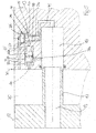
EP 1 998 054 A2 beschrieben. In einem beiderseits durch Zylinderdeckel 12 abgeschlossenen Zylindergehäuse 11 ist ein Zylinderkolben 13 als Träger einer Masse m hin und her beweglich geführt. Für seine Bewegung nach links in Richtung des Pfeils 14 wird über eine den rechten Zylinderdeckel 12 durchsetzende Anschlussleitung 15 Druckluft mit Arbeitdruck in den Zylinderinnenraum 16 eingeleitet. Auf der gegenüberliegenden Seite des Zylinders ist eine Endlagendämpfung für den Zylinderkolben 13 ausgebildet. Hierzu ist ein sich in axialer Richtung von dem Zylinderdeckel 12 in den Zylinderinnenraum 16 vorstehender Dämpfzapfen 17 ausgebildet, auf den der Zylinderkolben 13 mit einer in ihm ausgebildeten Ausnehmung 18 auffährt. Zur Entlüftung des in Fahrtrichtung des Zylinderkolbens 13 in Richtung des Pfeils 14 gelegenen Teils des Zylinderinnenraums 16 ist eine sich durch den Dämpfzapfen 17 erstreckende Anschlussbohrung 19 vorgesehen. Dabei verhält es sich so, dass zum Verfahren des Zylinderkolbens 13 in Richtung des Pfeils 14 der linke Teil des Zylinderinnenraumes 16 druckentlastet sein muss, damit die daraus durch die Bewegung des Zylinderkolbens 13 verdrängte Luft über die Anschlussleitung 19 abströmen kann. Somit herrscht während des Verfahrens des Zylinderkolbens 13 in Richtung des Pfeils 14 in dem linken Teil des Zylinderinnenraums ein Entlüftungsdruck, der unterhalb des Arbeitdruckes liegt. In gestrichelten Linien ist inFigur 1 weiterhin die Stellung des Zylinderkolbens 13 im Augenblick des Auffahrens auf den Dämpfzapfen 17 dargestellt, wobei in dieser Stellung die gewünschte Dämpfungsphase der entsprechend eingerichteten Endlagendämpfung beginnt. Dadurch wird zwischen dem Zylinderdeckel 12 und dem Zylinderkolben 13 ein Dämpfungsraum 20 abgeteilt, in welchem der zunächst herrschende Entlüftungsdruck durch die weitere Bewegung des Zylinderkolbens 13 in Richtung des Pfeils 14 ansteigt, wobei zur Ausführung der Endlagendämpfung die im Dämpfungsraum 20 anstehende Luft ebenfalls über einen noch zu beschreibenden Entlüftungsweg abzuführen ist. - Ein erstes Ausführungsbeispiel für einen derartigen Entlüftungsweg einschließlich einer Endlagendämpfung für die Bewegung des Zylinderkolbens 13 ist in
Figur 2 dargestellt, bei welchem die Bestandteile der Endlagendämpfung in dem ausFigur 1 ersichtlichen linken Zylinderdeckel 12 angeordnet sind. - Hierzu ist im Zylinderdeckel 12 ein Steuerventil 21 angeordnet, in dessen Kolbenraum 22 ein Steuerkolben 23 verschiebbar angeordnet ist. Auf seiner einen Seite weist der Steuerkolben einen Ansatz 24 als Endanschlag für seine Bewegung in dem Kolbenraum 22 auf. Auf der gegenüberliegenden Seite des Steuerkolbens 23 ist ein Steuerraum 25 als Bestandteil des Kolbenraumes 22 angeordnet, auf den nachfolgend eingegangen ist.
- Ferner ist in dem Zylinderdeckel 12 eine Schließanordnung 26 ausgebildet, mit einem in einem Hubraum 27 verschiebbar angeordneten Schließelement 28. Auf der einen Seite des Schließelements 28 ist ein Druckraum 29 ausgebildet, der einerseits über eine Leitungsverbindung 30 an die in dem Dämpfzapfen 17 ausgebildete Anschlussleitung 19 angeschlossen ist. Der Druckraum 29 ist weiterhin mittels einer Verbindungsbohrung 31 mit dem Steuerraum 25 des Steuerventils 21 verbunden, wobei diese Verbindungsbohrung 31 in einer entsprechenden Stellung des Schließelements 28 mittels eines an dem Schließelement 28 ausgebildeten Schließansatzes 32 und eines daran ausgebildeten Dichtungsbereichs 33 verschließbar ist.
- Zur Herstellung einer fixierten Ausgangsstellung ist der Steuerkolben 23 des Steuerventils 21 mittels einer in dem Steuerraum 25 angeordneten Feder 34 vorgespannt, wobei in seiner Neutralstellung der Steuerkolben 23 durch die Feder 34 in seine Endstellung mit einem Anschlag des Ansatzes 24 gegen die Wand des Kolbenraums 22 vorgespannt ist. Dementsprechend ist auch das Schließelement 28 mittels einer in dem Druckraum 29 der Schließanordnung 26 angeordneten Feder 35 in seine noch zu erläuternde Schließstellung vorgespannt, in welcher der Schließansatz 32 des Schließelements 28 die Verbindungsbohrung 31 zwischen dem Druckraum 29 und dem Steuerraum 25 des Steuerventils 21 freigibt.
- In dem Zylinderdeckel 12 ist schließlich ein aus drei Abschnitten 36a, b, c bestehender Entlüftungskanal ausgebildet. Dabei führt der erste Abschnitt 36a von dem Dämpfungsraum 20 in den Hubraum 27 der Schließanordnung 26, wobei in der Ausgangsstellung aufgrund der Vorspannung der Feder 35 das Schließelement 28 mit einem an ihm ausgebildeten Dichtungsbereich 38 den Hubraum 27 gegen den ersten Abschnitt 36a des Entlüftungskanals abschließt. Von dem Hubraum 27 führt dann ein zweiter Abschnitt 36b des Entlüftungskanals zum dem Steuerraum 25 gegenüberliegend angeordneten Entlüftungsraum 37 des Steuerventils 21 dergestalt, dass der Abgang des zweiten Abschnitts 36b vom Hubraum 27 der Schließanordnung 26 von dem Schließelement 28 in dessen verschobener Stellung freigebbar ist. Ein dritter Abschnitt 36c des Entlüftungskanals führt von dem Entlüftungsraum 37 des Steuerventils 21 zur Anschlussleitung 19 im Dämpfzapfen 17 derart, dass in der Ausgangsstellung der Abgang des dritten Abschnitts 36c des Entlüftungskanals aus dem Entlüftungsraum 37 von dem Steuerkolben 23 abgedeckt, von diesem aber in der verschobenen Stellung freigebbar ist.
- Bei der Bewegung des Zylinderkolbens 13 in Richtung des Dämpfzapfens 17 und Verdrängung der im Zylinderinnenraum 16 anstehenden Luft durch die im Dämpfzapfen 17 ausgebildete Anschlussleitung 19 steht zunächst der unterhalb des Arbeitsdruckes liegende Entlüftungsdruck über die Leitungsverbindung 30 im Druckraum 29 der Schließanordnung 26 und über die zwischen dem Druckraum 29 und dem Steuerraum 25 des Steuerventils 21 bestehende Verbindungsbohrung 31 auch im Steuerraum 25 des Steuerventils 21 an. Der im Druckraum 29 wie auch im Steuerraum 25 jeweils anstehende Entlüftungsdruck sorgt zunächst dafür, dass das Schließelement 28 druckausgeglichen gelagert ist, weil auf der durch den Dichtungsbereich 38 des Schließelements 28 definierten Schließseite der Schließanordnung 26 über den ersten Abschnitt 36a des Entlüftungskanals ebenfalls der Entlüftungsdruck ansteht. Die Feder 35 sorgt dabei für die Schließstellung des Schließelements 28 gegenüber dem ersten Abschnitt 36a des Entlüftungskanals. Soweit gleichermaßen auch im Steuerraum 25 des Steuerventils 21 der Entlüftungsdruck ansteht, ist durch eine bewusst fehlende Abdichtung des Steuerkolbens 23 gegen den dritten Abschnitt 36c des Entlüftungskanals dafür Sorge getragen, dass über den an die Anschlussleitung 19 angeschlossen dritten Abschnitt 36c des Entlüftungskanals ebenfalls der Entlüftungsdruck im Entlüftungsraum 37 des Steuerventils ansteht, wobei der Steuerkolben 23 durch die ihn beaufschlagende Feder 34 in der definierten Ausgangsstellung gehalten ist.
- Läuft nun der Zylinderkolben 13 auf den Dämpfzapfen 17 auf, wie dies mit Pfeil 40 und gestrichelter Linie in
Figur 2 angedeutet ist, so wird zunächst der Dämpfungsraum 20 gegen eine weitere Entlüftung über die Anschlussleitung 19 abgeschlossen, so dass bei einer weiteren Bewegung des Zylinderkolbens 13 der nun als Dämpfungsdruck bezeichnete Druck im Dämpfungsraum 20 ansteigt. Durch diesen Druckanstieg ist der Dämpfungsbeginn gekennzeichnet. - Wie beschrieben steht der im Augenblick des Dämpfungsbeginns noch im System anstehende Entlüftungsdruck insbesondere im Steuerraum 25 des Steuerventils 21 wie auch in dem Druckraum 29 der Schließanordnung 26 an. Der ab dem Dämpfungsbeginn im Dämpfungsraum 20 ansteigende Druck führt nun über den ersten Abschnitt 36a des Entlüftungskanals zu einer Druckbeaufschlagung des Schließelementes 28, so dass das Schließelement in seine Schließstellung bewegt wird, in welcher seiner Schließansatz 32 mit Dichtungsbereich 33 die Verbindungsbohrung 31 zum Steuerraum 25 des Steuerventils 21 verschließt. Hierdurch wird der zum Zeitpunkt des Druckanstieges im Dämpfungsraum 20 in dem Steuerraum 25 anstehende Entlüftungsdruck als Steuerdruck für den Steuerkolben 23 fixiert. Gleichzeitig wird durch die Schließbewegung des Schließelements 28 der von dem Hubraum 27 der Schließanordnung 26 wegführende zweite Abschnitt 36b des Entlüftungskanals freigegeben, so dass die mit zunehmendem Druck aus dem Dämpfungsraum 20 verdrängte Luft über die Abschnitte 36a, b des Entlüftungskanals in den Entlüftungsraum 37 des Steuerventils 21 eintritt und hier ebenfalls für einen Druckanstieg sorgt. Übersteigt dieser im Entlüftungsraum 37 jeweils anstehende, durch den anwachsenden Druck im Dämpfungsraum 20 anstehende Dämpfungsdruck den im Steuerraum 25 des Steuerventils 21 eingeschlossenen Entlüftungsdruck, so wird der Steuerkolben 23 in den Steuerraum 25 verschoben und gibt dabei den von dem Entlüftungsraum 37 abgehenden dritten Abschnitt 36c des Entlüftungskanals frei, so dass die aus dem Dämpfungsraum 20 verdrängte Luft über die nunmehr freigegebenen Abschnitte 36a, b, c des Entlüftungskanals bis in die Anschlussleitung 19 abströmen kann. Somit ist eine druckgesteuerte und damit dämpfende Ableitung der aus dem Dämpfungsraum 20 verdrängten Luft gegeben.
- Es können Fälle auftreten, in denen es aufgrund einer sehr langsamen Bewegung des Zylinderkolbens nur zu sehr geringen Druckunterschieden zwischen dem ab dem Dämpfungsbeginn im Dämpfungsraum 20 anstehenden Dämpfungsdruck und dem als Steuerdruck für den Steuerkolben 23 des Steuerventils 21 fixierten anfänglichen Entlüftungsdruck kommt, so dass der Steuerkolben nicht in seine den Querschnitt des über das Steuerventil 21 geführten Entlüftungsweges freigebende Stellung bewegt wird. Hierbei dient der schon angesprochene, durch die fehlende Abdichtung des Steuerkolbens 23 gegen den dritten Abschnitt 36c des Entlüftungskanals bedingte begrenzte offene Strömungsquerschnitt dazu, nach dem Öffnen des Schließelements 28 ein Abströmen der aus dem Dämpfungsraum 20 verdrängten Luft auch bei einer unveränderten Stellung des Steuerkolbens 23 zu ermöglichen.
- Wie nicht weiter dargestellt kann beispielsweise auf die Anordnung der den Steuerkolben 23 vorspannenden Feder 34 dann verzichtet sein, wenn in den dritten Abschnitt 36c des Entlüftungskanals ein Rückschlagventil mit einer vom Steuerventil 21 zur Anschlussleitung 19 gerichteten Durchlassrichtung eingeschaltet ist. In diesem Fall steht im Entlüftungsraum 37 des Steuerventils 21 vor Beginn der Endlagendämpfung kein Druck an, so dass der Steuerkolben 23 durch den in seinen Steuerraum 25 eingeleiteten Entlüftungsdruck in seiner definierten, zunächst den vom Entlüftungsraum 37 abgehenden dritten Abschnitt des Entlüftungskanals sperrenden Stellung gehalten ist.
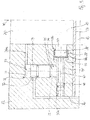
- Das in
Figur 3 dargestellte Ausführungsbeispiel unterscheidet sich von dem zuvor beschriebenen Ausführungsbeispiel durch eine geänderte Anordnung von Steuerventil 21 und Schließanordnung 26 im Zylinderdeckel 12 sowie durch den Anschluss der Leitungsverbindung 30 zwischen dem Druckraum 29 der Schließanordnung 26 und damit auch dem Steuerraum 25 des Steuerventils 21 unmittelbar an den Dämpfungsraum 20. Hierbei ist der Entlüftungskanal nicht mehr über die Schließanordnung geführt, vielmehr ist nur noch ein vom Dämpfungsraum 20 zum Entlüftungsraum 37 des Steuerventils 21 führender Abschnitt 36a des Entlüftungskanals und ein vom Entlüftungsraum 37 zur Anschlussleitung 19 führender Abschnitt 36c des Dämpfungskanals vorgesehen. Dieser Entlüftungsweg ist vor Dämpfungsbeginn durch das Steuerventil 21 bzw. dessen Steuerkolben 23 im Wesentlichen gegen den Dämpfungsraum 20 gesperrt, wobei jedoch wie zuFigur 2 beschrieben aufgrund der fehlenden Abdichtung des Steuerkolbens 23 gegen die Wandung des Kolbenraumes 22 im Bereich des Eintritts des Abschnitts 36c des Entlüftungskanals ein Abströmweg auch in den Fällen zur Verfügung steht, in denen sich bei langsamer Fahrweise des Zylinderkolbens 13 nur ein sehr geringer Druckunterschied zwischen dem Dämpfungsdruck und dem als Steuerdruck fixierten Entlüftungsdruck einstellt. - Die im Zylinderdeckel 12 angeordnete Schließanordnung 26 ist über eine Zuleitung 50 mit dem Dämpfungsraum 20 verbunden. Das Schließelement 28 ist in dem Hubraum 27 der Schließanordnung 26 in einer nicht abgedichteten Weise geführt, so dass die im Dämpfungsraum 20 anstehende Luft zunächst an dem Schließelement 28 vorbei in einen mit dem Steuerraum 25 des Steuerventils 21 verbundenen Leitungsabschnitt 45 strömen kann. Die Schließstellung des Schließelementes 28 zum Abschluss des Steuerraums 25 gegen den Dämpfungsraum 20 ist durch einen Dichtungssitz 46 zwischen dem Hubraum 27 der Schließanordnung 26 und dem Leitungsabschnitt 45 gebildet, auf dem das Schließelement 28 in seiner Schließstellung mit dem an ihm ausgebildeten Dichtungsbereich 38a aufsitzt. Weiterhin ist der Leitungsabschnitt 45 durchschlägig mit dem Abschnitt 36c des Entlüftungskanals verbunden, wobei in dem zwischen dem Abschnitt 36c des Entlüftungskanals und dem Anschluss des Steuerraums 25 des Steuerventils 21 gelegenen Bereich des Leitungsabschnitts 45 ein mit dem Schließelement 28 über eine Stange 47 verbundener Druckkolben 48 dichtend geführt ist, der seinerseits von einer Feder 35a in eine Stellung des Schließelements 28 vorspannt ist, in welcher das Schließelement 28 von dem Dichtungssitz 46 abgehoben ist und somit den Strömungsweg vom Dämpfungsraum 20 in den Steuerraum 25 des Steuerventils 21 freigibt. Aufgrund der Verbindung des Leitungsabschnitts 45 mit dem an die Anschlussleitung 19 angeschlossenen Abschnitt 36c des Entlüftungskanals ist wegen auf beiden Seiten von Schließelement 28 bzw. Druckkolben 48 vor Beginn der Dämpfung anliegenden Drucks eine druckausgeglichene Stellung des Schließelements 28 gewährleistet.
- Im Grundsatz herrschen die gleichen Funktionsverhältnisse vor, wie zu Figur 2 eingehend beschrieben. Der im Dämpfungsraum 20 zu Dämpfungsbeginn (Pfeil 40) anstehende Entlüftungsdruck steht einerseits über den Abschnitt 36a des Entlüftungskanals im Entlüftungsraum 37 des Steuerventils 21 an. Dieser Entlüftungsdruck steht weiterhin über die Zuleitung 50 und den offenen Strömungsweg in der Schließanordnung 26 auch im Hubraum 27 der Schließanordnung 26, dem Leitungsabschnitt 45 und auch im Steuerraum 25 des Steuerventils 21 an, so dass sowohl der Steuerkolben 23 wie auch das Schließelement 28 druckausgeglichen angeordnet sind. Mittels der entsprechenden Federn 34 sowie 35a sind Steuerkolben 23 und Schließelement 28 jeweils in einer definierten Ausgangsstellung gehalten. Steigt der Druck im Dämpfungsraum 20 an, so wird das Schließelement 28 wiederum in Anlage seines Dichtungsbereichs 38a am Dichtungssitz 46 verschoben, so dass der im Steuerraum 25 des Steuerventils 21 zum Zeitpunkt des Dämpfungsbeginns anstehende Entlüftungsdruck im Steuerraum 25 eingeschlossen ist und hier als fixierter Steuerdruck für den Steuerkolben 23 wirkt. Der im Dämpfungsraum 20 ansteigende Druck steht über den Abschnitt 36a des Entlüftungskanals auch im Entlüftungsraum 37 des Steuerventils 21 an, und sobald der Dämpfungsdruck den durch den Entlüftungsdruck gekennzeichneten Steuerdruck des Steuerventils 21 übersteigt, wird der Steuerkolben 23 in seine Stellung verschoben, in welcher er den Anschluss des Abschnittes 36c des Entlüftungskanals freigibt, so dass die im Dämpfungsraum 20 anstehende Luft über den Entlüftungsweg 36a, 36c in die Anschlussleitung 19 abströmen kann.
- In den
Figuren 4 und5 sind die den zuvor beschriebenen Ausführungsbeispielen gemäßFiguren 2 und3 entsprechenden Anordnungen von Steuerelement 21 und Schließanordnung 26 einschließlich der zugehörigen Leitungswege nunmehr von dem Zylinderdeckel 12 (Figuren 2, 3 ) in den Zylinderkolben 13 verlegt mit der Maßgabe, dass bei dem der Ausführungsform gemäßFigur 2 entsprechenden Ausführungsbeispiel gemäßFigur 4 die Leitungsverbindung 30 wie auch der dritte Abschnitt 36c des Entlüftungskanals jeweils in der im Zylinderkolben 13 ausgebildeten Ausnehmung 18 enden, die ab dem Dämpfungsbeginn mit Auflaufen des Zylinderkolbens 13 auf den Dämpfzapfen 17 Bestandteil der im Dämpfzapfen 17 verlaufenden Anschlussbohrung 19 wird, über die die Entlüftung des Dämpfungsraums 20 erfolgt. Ansonsten vollziehen sich die gleichen Vorgänge wie zuFigur 2 beschrieben. - Entsprechendes gilt auch für das in
Figur 5 dargestellte Ausführungsbeispiel, wobei hier zur Herstellung einer druckausgeglichenen Stellung des Schließelements 28 mit Druckkolben 48 vor Beginn der Dämpfung noch ein zusätzlicher Kanal 49 zwischen dem Leitungsabschnitt 45 und der Ausnehmung 18 ausgebildet ist.
Claims (16)
- Pneumatikzylinder (10) mit einem Zylindergehäuse (11) und einem darin unter Druckeinwirkung hin und her gehenden Zylinderkolben (13), der jeweils in seiner einen Bewegungsrichtung über eine wechselweise als Druckleitung und Entlüftungsleitung wirkende Anschlussleitung (15) mit einem Arbeitsdruck beaufschlagt ist und auf seiner jeweils gegenüberliegenden Seite die im Zylinderinnenraum (16) mit einem geringeren Entlüftungsdruck anstehende Luft aus dem Zylinderinnenraum (16) verdrängt, wobei an zumindest einem Ende des Zylinderkolbenweges eine Dämpfungsanordnung mit einem im Zylinderinnenraum (16) angeordneten und von dem sich bewegenden Zylinderkolben (13) begrenzten Dämpfungsraum (20) angeordnet ist, welcher zur Endlagendämpfung des Zylinderkolbens (13) über einen Entlüftungsweg mit einem darin eingeschalteten Steuerventil (21) gesteuert entlüftet wird, wobei das pneumatisch gesteuerte Steuerventil (21) einen Steuerkolben (23) umfasst, dessen dem Entlüftungsweg abgewandte Steuerseite von einem in einem Steuerraum (25) anstehenden pneumatischen Druck beaufschlagt ist, wobeia) der Steuerraum (25) des Steuerventils (21) mittels einer Leitungsverbindung (30; 50, 45) mit einem unter Entlüftungsdruck stehenden Bereich der Dämpfungsanordnung verbunden ist undb) in die Leitungsverbindung (30; 50, 45) eine Schließanordnung (26) mit einem gesteuerten Schließelement (28) eingeschaltet ist, dadurch gekennzeichnet, dass die Schließanordnung (26) derart ausgebildet ist, dass die Leitungsverbindung (30; 50, 45) durch eine gesteuerte Bewegung des Schließelements (28) bei Dämpfungsbeginn unterbrochen wird, so dass mittels des Schließelements (28) der im Steuerraum (25) des Steuerventils (21) jeweils aktuell anstehende Entlüftungsdruck bei dem durch einen Druckanstieg im Dämpfungsraum (20) charakterisierten Dämpfungsbeginnb1) im Steuerraum (25) einschließbar ist undb2) als dergestalt fixierter Steuerdruck auf den Steuerkolben (23) des Steuerventils (21) wirkt undb3) den Öffnungszeitpunkt des Steuerventils (21) zur Freigabe des Entlüftungsweges festlegt.
- Pneumatikzylinder nach Anspruch 1, der derart ausgebildet ist, dass die Bewegung des Schließelements in Abhängigkeit von einem bei Dämpfungsbeginn abgegriffenen Steuersignal elektrisch gesteuert ist.
- Pneumatikzylinder nach Anspruch 1, der derart ausgebildet ist, dass die Bewegung des Schließelements mechanisch durch die Relativbewegung des Zylinderkolbens zum Zylindergehäuse gesteuert ist.
- Pneumatikzylinder nach Anspruch 1, der derart ausgebildet ist, dass die Bewegung des Schließelements (28) der Schließanordnung (26) in seine den Steuerraum (25) des Steuerventils (21) abschließende Schließstellung pneumatisch durch den im Dämpfungsraum (20) bei Dämpfungsbeginn ansteigenden Druck gesteuert ist.
- Pneumatikzylinder nach Anspruch 4, dadurch gekennzeichnet, dass das Schließelement (28) als in einem Hubraum (27) längsbewegliches Kolbenelement ausgebildet ist, wobei an der der Richtung der Schließbewegung abgewandten Druckseite des Schließelementes (28) der im Dämpfungsraum (20) jeweils anstehende Druck anliegt und der auf der gegenüberliegenden Seite des Schließelements (28) liegende Druckraum (29) mit dem Steuerraum (25) des Steuerventils (21) verbunden ist.
- Pneumatikzylinder nach Anspruch 4 oder 5, dadurch gekennzeichnet, dass im Bereich des Endanschlages des Zylinderkolbens (13) ein sich in axialer Richtung in den Zylinderinnenraum (16) erstreckender Dämpfzapfen (17) mit der durch diesen hindurchgeführten Anschlussleitung (19) angeordnet und der Zylinderkolben (13) mit einer den Dämpfzapfen (17) aufnehmenden Ausnehmung (18) ausgeführt ist.
- Pneumatikzylinder nach einem der Ansprüche 4 bis 6, dadurch gekennzeichnet, dass das Steuerventil (21) und die Schließanordnung (26) im Zylinderdeckel (12) des Pneumatikzylinders (10) angeordnet sind.
- Pneumatikzylinder nach Anspruch 7, dadurch gekennzeichnet, dass die Leitungsverbindung zwischen dem Steuerraum (25) des Steuerventils (21) und dem den Entlüftungsdruck aufweisenden Bereich der Dämpfungsanordnung durch einen zwischen dem mit dem Steuerraum (25) verbundenen Druckraum (29) der Schließanordnung (26) und der Anschlussleitung (19) verlaufenden Verbindungskanal (30) gebildet ist, und dass der Entlüftungsweg aus einem von dem Dämpfungsraum (20) ausgehenden und über den druckseitigen Hubraum (27) der Schließanordnung (26) und über das Steuerventil (21) bis zur Anschlussleitung (19) verlaufenden Entlüftungskanal (36a, b, c) besteht, der vor Dämpfungsbeginn durch die Schließanordnung (26) gegen den Dämpfungsraum (20) gesperrt ist.
- Pneumatikzylinder nach Anspruch 8, dadurch gekennzeichnet, dass in den zwischen dem Steuerventil (21) und der Anschlussleitung (19) verlaufenden Abschnitt (36c) des Entlüftungsweges ein Rückschlagventil mit einer vom Steuerventil (21) zur Anschlussleitung (19) gerichteten Durchlassrichtung eingeschaltet ist.
- Pneumatikzylinder nach Anspruch 7, dadurch gekennzeichnet, dass die Leitungsverbindung zwischen dem Steuerraum (25) des Steuerventils (21) und dem vor Dämpfungsbeginn den Entlüftungsdruck aufweisenden Dämpfungsraum (20) durch einen die Schließanordnung (26) aufnehmenden Verbindungskanal (45, 50) ausgebildet ist, und dass der Entlüftungsweg aus einem von dem Dämpfungsraum (20) ausgehenden und über das Steuerventil (21) bis zur Anschlussleitung (19) verlaufenden Entlüftungskanal (36a, c) besteht.
- Pneumatikzylinder nach einem der Ansprüche 4 bis 6, dadurch gekennzeichnet, dass Steuerventil (21) und Schließanordnung (26) im Zylinderkolben (13) des Pneumatikzylinders (10) angeordnet sind.
- Pneumatikzylinder nach Anspruch 11, dadurch gekennzeichnet, dass die Leitungsverbindung zwischen dem Steuerraum (25) des Steuerventils (21) und dem den Entlüftungsdruck aufweisenden Bereich der Dämpfungsanordnung durch einen zwischen dem mit dem Steuerraum (25) verbundenen Druckraum (29) der Schließanordnung (26) und der Ausnehmung (18) des Zylinderkolbens (13) verlaufenden Verbindungskanal (30) ausgebildet ist, und dass der Entlüftungsweg aus einem von dem Dämpfungsraum (20) ausgehenden und über den druckseitigen Hubraum (27) der Schließanordnung (26) und über das Steuerventil (21) bis in die Ausnehmung (18) des Zylinderkolbens (13) verlaufenden Entlüftungskanal (36 a, b, c) besteht, der vor Dämpfungsbeginn durch die Schließanordnung (26) gegen den Dämpfungsraum (20) gesperrt ist,
- Pneumatikzylinder nach Anspruch 11, dadurch gekennzeichnet, dass die Leitungsverbindung zwischen dem Steuerraum (25) des Steuerventils (21) und dem vor Dämpfungsbeginn den Entlüftungsdruck aufweisenden Dämpfungsraum (20) durch einen die Schließanordnung (26) aufnehmenden Verbindungskanal (45, 50) ausgebildet ist, und dass der Entlüftungsweg aus einem von dem Dämpfungsraum (20) ausgehenden und über das Steuerventil (21) bis zur Ausnehmung (18) des Zylinderkolbens (13) verlaufenden Entlüftungskanal (36a, c) besteht.
- Pneumatikzylinder nach einem der Ansprüche 1 bis 13, dadurch gekennzeichnet, dass der Steuerkolben (23) des Steuerventils (21) ohne eine Abdichtung gegenüber dem Entlüftungsweg (36a, b, c) im Ventilgehäuse des Steuerventils (21) angeordnet ist.
- Pneumatikzylinder nach einem der Ansprüche 1 bis 14, dadurch gekennzeichnet, dass der Steuerkolben (23) des Steuerventils (21) und das Schließelement (28) der Schließanordnung (26) vor Dämpfungsbeginn jeweils durch zugeordnete Federanordnungen in einer definierten Ausgangsstellung gehalten sind,
- Pneumatikzylinder nach einem der Ansprüche 1 bis 15, dadurch gekennzeichnet, dass der Steuerkolben (23) des Steuerventils (21) und das Schließelement (28) der Schließanordnung (26) durch Anordnung zusätzlicher Leitungsverbindungen vor Dämpfungsbeginn jeweils druckausgeglichen angeordnet sind.
Applications Claiming Priority (1)
| Application Number | Priority Date | Filing Date | Title |
|---|---|---|---|
| DE102011051400A DE102011051400B3 (de) | 2011-06-28 | 2011-06-28 | Pneumatikzylinder mit selbstjustierender Endlagendämpfung |
Publications (3)
| Publication Number | Publication Date |
|---|---|
| EP2541073A2 EP2541073A2 (de) | 2013-01-02 |
| EP2541073A3 EP2541073A3 (de) | 2016-11-02 |
| EP2541073B1 true EP2541073B1 (de) | 2020-08-05 |
Family
ID=46083178
Family Applications (1)
| Application Number | Title | Priority Date | Filing Date |
|---|---|---|---|
| EP12171413.3A Active EP2541073B1 (de) | 2011-06-28 | 2012-06-11 | Pneumatikzylinder mit selbstjustierender Endlagendämpfung |
Country Status (3)
| Country | Link |
|---|---|
| US (1) | US9080584B2 (de) |
| EP (1) | EP2541073B1 (de) |
| DE (1) | DE102011051400B3 (de) |
Families Citing this family (3)
| Publication number | Priority date | Publication date | Assignee | Title |
|---|---|---|---|---|
| WO2016205087A1 (en) * | 2015-06-15 | 2016-12-22 | Board Of Supervisors Of Louisiana State University And Agricultural And Mechanical College | Thermoplastic cellulosic fiber granules useful as infill materials for artificial turf |
| CN109084967A (zh) * | 2017-06-14 | 2018-12-25 | 鸿富锦精密电子(天津)有限公司 | 推拉测试装置 |
| CN115095576B (zh) * | 2022-08-01 | 2025-02-11 | 泸州合成液压件有限公司 | 一种往返缓冲液压缸 |
Family Cites Families (9)
| Publication number | Priority date | Publication date | Assignee | Title |
|---|---|---|---|---|
| AT213677B (de) * | 1958-07-23 | 1961-02-27 | Hydraulik Rochlitz Veb | Hydraulische Dämpfungseinrichtung an geradlinigen Kolbengetrieben |
| GB1351958A (en) * | 1971-09-14 | 1974-05-15 | Martonair Ltd | Pneumatic actuators |
| DE2326417C3 (de) * | 1973-05-24 | 1980-01-10 | Maschinenfabrik Glueckauf Beukenberg Gmbh & Co, 4650 Gelsenkirchen | Hydraulik-Zylinder mit Endlagendämpfung |
| JP2598210B2 (ja) * | 1992-12-01 | 1997-04-09 | エスエムシー株式会社 | シリンダ装置 |
| FR2781016B1 (fr) * | 1998-07-08 | 2002-03-08 | Aro | Verin a precourse d'approche et course de travail, pour la manoeuvre d'un outil |
| US6612410B1 (en) * | 2001-10-17 | 2003-09-02 | Yevgeny Antonovsky | High frequency shock absorber and accelerator |
| DE102006041707B4 (de) * | 2006-05-10 | 2009-01-02 | Tünkers Maschinenbau Gmbh | Kolben-Zylinder-Einheit (Arbeitszylinder) zum Spannen, und/oder Pressen, und/oder Fügen, und/oder Stanzen, und/oder Prägen, und/oder Lochen und/oder Schweißen, zum Beispiel unter Zwischenschaltung einer Kniehebelgelenkanordnung |
| EP1998054B1 (de) | 2007-05-24 | 2014-08-13 | Parker Origa Holding AG | Pneumatikzylinder mit einer selbsteinstellenden Endlagendämpfung und entsprechendes Verfahren |
| WO2010096737A1 (en) * | 2009-02-23 | 2010-08-26 | Albrecht David E | Cylinder phaser valves |
-
2011
- 2011-06-28 DE DE102011051400A patent/DE102011051400B3/de active Active
-
2012
- 2012-06-11 EP EP12171413.3A patent/EP2541073B1/de active Active
- 2012-06-26 US US13/533,333 patent/US9080584B2/en active Active
Non-Patent Citations (1)
| Title |
|---|
| None * |
Also Published As
| Publication number | Publication date |
|---|---|
| US9080584B2 (en) | 2015-07-14 |
| US20130001031A1 (en) | 2013-01-03 |
| EP2541073A3 (de) | 2016-11-02 |
| DE102011051400B3 (de) | 2012-06-06 |
| EP2541073A2 (de) | 2013-01-02 |
Similar Documents
| Publication | Publication Date | Title |
|---|---|---|
| DE3434033A1 (de) | Pneumatischer zylinder mit daempfungsmechanik und verfahren zum daempfen des pneumatischen zylinders | |
| DE3323363A1 (de) | Vorgesteuertes druckreduzierventil | |
| EP1860328A1 (de) | Einrichtung zur Steuerung eines pneumatischen, insbesondere doppelwirkenden, Zylinders | |
| EP0829668B1 (de) | Magnetventil | |
| DE102015109474A1 (de) | Umschaltventil und Pleuel mit einem Umschaltventil | |
| EP1631746B1 (de) | Hydraulischer antrieb zum verlagern eines stellgliedes | |
| DE102014119592B4 (de) | Ventil | |
| DE19637291C2 (de) | Vorrichtung zur Endlagendämpfung | |
| DE102011051400B3 (de) | Pneumatikzylinder mit selbstjustierender Endlagendämpfung | |
| DE102004023255B3 (de) | Druckminderventil | |
| EP1884692A1 (de) | Pneumatikventil mit schneller Rückstellung | |
| DE1813145C2 (de) | Luftverteiler für eine druckluftbetriebene hydropneumatische Pumpe zur Förderung von Druckflüssigkeit | |
| EP2951067B1 (de) | Hubzylinder zur betätigung einer magnetschienenbremse | |
| DE2909504C2 (de) | ||
| DE10010690A1 (de) | Ventil | |
| DE4421357A1 (de) | Pneumatisches Wegeventil | |
| DE10255524B4 (de) | Elektromagnetisches 3/2-Wegesitzventil mit A-Kompensation | |
| EP2697105B1 (de) | Bremskraftverstärker mit stellungsabhängigem druckausgleich | |
| DE102018201655B4 (de) | Beschleunigungsventil für selbsttätige Druckluftbremsen von Schienenfahrzeugen | |
| DE102008060650A1 (de) | Ventil mit Endlagen-Dämpfungseinrichtung | |
| DE10147299A1 (de) | Vorrichtung zur Steuerung eines Öffnungsquerschnitts in einem Verbrennungszylinder einer Brennkraftmaschine | |
| DE29609485U1 (de) | Vorrichtung zur Verzögerung einer bewegten Masse | |
| DE102015200296A1 (de) | Dreiwegeventil | |
| DE2155706C3 (de) | Lastabhängig arbeitendes Bremsdrucksteuerventil für eine hydraulische Fahrzeugbremsanlage | |
| DE3326373A1 (de) | Bremssteuerventileinrichtung einer indirekt wirkenden druckluftbremse fuer schienenfahrzeuge |
Legal Events
| Date | Code | Title | Description |
|---|---|---|---|
| PUAI | Public reference made under article 153(3) epc to a published international application that has entered the european phase |
Free format text: ORIGINAL CODE: 0009012 |
|
| AK | Designated contracting states |
Kind code of ref document: A2 Designated state(s): AL AT BE BG CH CY CZ DE DK EE ES FI FR GB GR HR HU IE IS IT LI LT LU LV MC MK MT NL NO PL PT RO RS SE SI SK SM TR |
|
| AX | Request for extension of the european patent |
Extension state: BA ME |
|
| PUAL | Search report despatched |
Free format text: ORIGINAL CODE: 0009013 |
|
| AK | Designated contracting states |
Kind code of ref document: A3 Designated state(s): AL AT BE BG CH CY CZ DE DK EE ES FI FR GB GR HR HU IE IS IT LI LT LU LV MC MK MT NL NO PL PT RO RS SE SI SK SM TR |
|
| AX | Request for extension of the european patent |
Extension state: BA ME |
|
| RIC1 | Information provided on ipc code assigned before grant |
Ipc: F15B 15/22 20060101ALI20160926BHEP Ipc: F15B 15/20 20060101AFI20160926BHEP |
|
| STAA | Information on the status of an ep patent application or granted ep patent |
Free format text: STATUS: REQUEST FOR EXAMINATION WAS MADE |
|
| 17P | Request for examination filed |
Effective date: 20170428 |
|
| RBV | Designated contracting states (corrected) |
Designated state(s): AL AT BE BG CH CY CZ DE DK EE ES FI FR GB GR HR HU IE IS IT LI LT LU LV MC MK MT NL NO PL PT RO RS SE SI SK SM TR |
|
| STAA | Information on the status of an ep patent application or granted ep patent |
Free format text: STATUS: EXAMINATION IS IN PROGRESS |
|
| 17Q | First examination report despatched |
Effective date: 20180314 |
|
| GRAP | Despatch of communication of intention to grant a patent |
Free format text: ORIGINAL CODE: EPIDOSNIGR1 |
|
| STAA | Information on the status of an ep patent application or granted ep patent |
Free format text: STATUS: GRANT OF PATENT IS INTENDED |
|
| INTG | Intention to grant announced |
Effective date: 20200325 |
|
| GRAS | Grant fee paid |
Free format text: ORIGINAL CODE: EPIDOSNIGR3 |
|
| GRAA | (expected) grant |
Free format text: ORIGINAL CODE: 0009210 |
|
| STAA | Information on the status of an ep patent application or granted ep patent |
Free format text: STATUS: THE PATENT HAS BEEN GRANTED |
|
| AK | Designated contracting states |
Kind code of ref document: B1 Designated state(s): AL AT BE BG CH CY CZ DE DK EE ES FI FR GB GR HR HU IE IS IT LI LT LU LV MC MK MT NL NO PL PT RO RS SE SI SK SM TR |
|
| REG | Reference to a national code |
Ref country code: GB Ref legal event code: FG4D Free format text: NOT ENGLISH |
|
| REG | Reference to a national code |
Ref country code: CH Ref legal event code: EP |
|
| REG | Reference to a national code |
Ref country code: AT Ref legal event code: REF Ref document number: 1299097 Country of ref document: AT Kind code of ref document: T Effective date: 20200815 |
|
| REG | Reference to a national code |
Ref country code: DE Ref legal event code: R096 Ref document number: 502012016258 Country of ref document: DE |
|
| REG | Reference to a national code |
Ref country code: IE Ref legal event code: FG4D Free format text: LANGUAGE OF EP DOCUMENT: GERMAN |
|
| REG | Reference to a national code |
Ref country code: LT Ref legal event code: MG4D |
|
| REG | Reference to a national code |
Ref country code: NL Ref legal event code: MP Effective date: 20200805 |
|
| PG25 | Lapsed in a contracting state [announced via postgrant information from national office to epo] |
Ref country code: PT Free format text: LAPSE BECAUSE OF FAILURE TO SUBMIT A TRANSLATION OF THE DESCRIPTION OR TO PAY THE FEE WITHIN THE PRESCRIBED TIME-LIMIT Effective date: 20201207 Ref country code: GR Free format text: LAPSE BECAUSE OF FAILURE TO SUBMIT A TRANSLATION OF THE DESCRIPTION OR TO PAY THE FEE WITHIN THE PRESCRIBED TIME-LIMIT Effective date: 20201106 Ref country code: FI Free format text: LAPSE BECAUSE OF FAILURE TO SUBMIT A TRANSLATION OF THE DESCRIPTION OR TO PAY THE FEE WITHIN THE PRESCRIBED TIME-LIMIT Effective date: 20200805 Ref country code: SE Free format text: LAPSE BECAUSE OF FAILURE TO SUBMIT A TRANSLATION OF THE DESCRIPTION OR TO PAY THE FEE WITHIN THE PRESCRIBED TIME-LIMIT Effective date: 20200805 Ref country code: LT Free format text: LAPSE BECAUSE OF FAILURE TO SUBMIT A TRANSLATION OF THE DESCRIPTION OR TO PAY THE FEE WITHIN THE PRESCRIBED TIME-LIMIT Effective date: 20200805 Ref country code: HR Free format text: LAPSE BECAUSE OF FAILURE TO SUBMIT A TRANSLATION OF THE DESCRIPTION OR TO PAY THE FEE WITHIN THE PRESCRIBED TIME-LIMIT Effective date: 20200805 Ref country code: NO Free format text: LAPSE BECAUSE OF FAILURE TO SUBMIT A TRANSLATION OF THE DESCRIPTION OR TO PAY THE FEE WITHIN THE PRESCRIBED TIME-LIMIT Effective date: 20201105 Ref country code: ES Free format text: LAPSE BECAUSE OF FAILURE TO SUBMIT A TRANSLATION OF THE DESCRIPTION OR TO PAY THE FEE WITHIN THE PRESCRIBED TIME-LIMIT Effective date: 20200805 Ref country code: BG Free format text: LAPSE BECAUSE OF FAILURE TO SUBMIT A TRANSLATION OF THE DESCRIPTION OR TO PAY THE FEE WITHIN THE PRESCRIBED TIME-LIMIT Effective date: 20201105 |
|
| PG25 | Lapsed in a contracting state [announced via postgrant information from national office to epo] |
Ref country code: RS Free format text: LAPSE BECAUSE OF FAILURE TO SUBMIT A TRANSLATION OF THE DESCRIPTION OR TO PAY THE FEE WITHIN THE PRESCRIBED TIME-LIMIT Effective date: 20200805 Ref country code: NL Free format text: LAPSE BECAUSE OF FAILURE TO SUBMIT A TRANSLATION OF THE DESCRIPTION OR TO PAY THE FEE WITHIN THE PRESCRIBED TIME-LIMIT Effective date: 20200805 Ref country code: LV Free format text: LAPSE BECAUSE OF FAILURE TO SUBMIT A TRANSLATION OF THE DESCRIPTION OR TO PAY THE FEE WITHIN THE PRESCRIBED TIME-LIMIT Effective date: 20200805 Ref country code: PL Free format text: LAPSE BECAUSE OF FAILURE TO SUBMIT A TRANSLATION OF THE DESCRIPTION OR TO PAY THE FEE WITHIN THE PRESCRIBED TIME-LIMIT Effective date: 20200805 Ref country code: IS Free format text: LAPSE BECAUSE OF FAILURE TO SUBMIT A TRANSLATION OF THE DESCRIPTION OR TO PAY THE FEE WITHIN THE PRESCRIBED TIME-LIMIT Effective date: 20201205 |
|
| PG25 | Lapsed in a contracting state [announced via postgrant information from national office to epo] |
Ref country code: EE Free format text: LAPSE BECAUSE OF FAILURE TO SUBMIT A TRANSLATION OF THE DESCRIPTION OR TO PAY THE FEE WITHIN THE PRESCRIBED TIME-LIMIT Effective date: 20200805 Ref country code: DK Free format text: LAPSE BECAUSE OF FAILURE TO SUBMIT A TRANSLATION OF THE DESCRIPTION OR TO PAY THE FEE WITHIN THE PRESCRIBED TIME-LIMIT Effective date: 20200805 Ref country code: CZ Free format text: LAPSE BECAUSE OF FAILURE TO SUBMIT A TRANSLATION OF THE DESCRIPTION OR TO PAY THE FEE WITHIN THE PRESCRIBED TIME-LIMIT Effective date: 20200805 Ref country code: SM Free format text: LAPSE BECAUSE OF FAILURE TO SUBMIT A TRANSLATION OF THE DESCRIPTION OR TO PAY THE FEE WITHIN THE PRESCRIBED TIME-LIMIT Effective date: 20200805 Ref country code: RO Free format text: LAPSE BECAUSE OF FAILURE TO SUBMIT A TRANSLATION OF THE DESCRIPTION OR TO PAY THE FEE WITHIN THE PRESCRIBED TIME-LIMIT Effective date: 20200805 |
|
| REG | Reference to a national code |
Ref country code: DE Ref legal event code: R097 Ref document number: 502012016258 Country of ref document: DE |
|
| PG25 | Lapsed in a contracting state [announced via postgrant information from national office to epo] |
Ref country code: AL Free format text: LAPSE BECAUSE OF FAILURE TO SUBMIT A TRANSLATION OF THE DESCRIPTION OR TO PAY THE FEE WITHIN THE PRESCRIBED TIME-LIMIT Effective date: 20200805 |
|
| PLBE | No opposition filed within time limit |
Free format text: ORIGINAL CODE: 0009261 |
|
| STAA | Information on the status of an ep patent application or granted ep patent |
Free format text: STATUS: NO OPPOSITION FILED WITHIN TIME LIMIT |
|
| PG25 | Lapsed in a contracting state [announced via postgrant information from national office to epo] |
Ref country code: SK Free format text: LAPSE BECAUSE OF FAILURE TO SUBMIT A TRANSLATION OF THE DESCRIPTION OR TO PAY THE FEE WITHIN THE PRESCRIBED TIME-LIMIT Effective date: 20200805 |
|
| 26N | No opposition filed |
Effective date: 20210507 |
|
| PG25 | Lapsed in a contracting state [announced via postgrant information from national office to epo] |
Ref country code: SI Free format text: LAPSE BECAUSE OF FAILURE TO SUBMIT A TRANSLATION OF THE DESCRIPTION OR TO PAY THE FEE WITHIN THE PRESCRIBED TIME-LIMIT Effective date: 20200805 |
|
| PG25 | Lapsed in a contracting state [announced via postgrant information from national office to epo] |
Ref country code: MC Free format text: LAPSE BECAUSE OF FAILURE TO SUBMIT A TRANSLATION OF THE DESCRIPTION OR TO PAY THE FEE WITHIN THE PRESCRIBED TIME-LIMIT Effective date: 20200805 |
|
| REG | Reference to a national code |
Ref country code: CH Ref legal event code: PL |
|
| REG | Reference to a national code |
Ref country code: BE Ref legal event code: MM Effective date: 20210630 |
|
| PG25 | Lapsed in a contracting state [announced via postgrant information from national office to epo] |
Ref country code: LU Free format text: LAPSE BECAUSE OF NON-PAYMENT OF DUE FEES Effective date: 20210611 |
|
| PG25 | Lapsed in a contracting state [announced via postgrant information from national office to epo] |
Ref country code: LI Free format text: LAPSE BECAUSE OF NON-PAYMENT OF DUE FEES Effective date: 20210630 Ref country code: IE Free format text: LAPSE BECAUSE OF NON-PAYMENT OF DUE FEES Effective date: 20210611 Ref country code: CH Free format text: LAPSE BECAUSE OF NON-PAYMENT OF DUE FEES Effective date: 20210630 |
|
| PG25 | Lapsed in a contracting state [announced via postgrant information from national office to epo] |
Ref country code: BE Free format text: LAPSE BECAUSE OF NON-PAYMENT OF DUE FEES Effective date: 20210630 |
|
| REG | Reference to a national code |
Ref country code: AT Ref legal event code: MM01 Ref document number: 1299097 Country of ref document: AT Kind code of ref document: T Effective date: 20210611 |
|
| PG25 | Lapsed in a contracting state [announced via postgrant information from national office to epo] |
Ref country code: AT Free format text: LAPSE BECAUSE OF NON-PAYMENT OF DUE FEES Effective date: 20210611 |
|
| PG25 | Lapsed in a contracting state [announced via postgrant information from national office to epo] |
Ref country code: HU Free format text: LAPSE BECAUSE OF FAILURE TO SUBMIT A TRANSLATION OF THE DESCRIPTION OR TO PAY THE FEE WITHIN THE PRESCRIBED TIME-LIMIT; INVALID AB INITIO Effective date: 20120611 Ref country code: CY Free format text: LAPSE BECAUSE OF FAILURE TO SUBMIT A TRANSLATION OF THE DESCRIPTION OR TO PAY THE FEE WITHIN THE PRESCRIBED TIME-LIMIT Effective date: 20200805 |
|
| P01 | Opt-out of the competence of the unified patent court (upc) registered |
Effective date: 20230524 |
|
| PG25 | Lapsed in a contracting state [announced via postgrant information from national office to epo] |
Ref country code: MK Free format text: LAPSE BECAUSE OF FAILURE TO SUBMIT A TRANSLATION OF THE DESCRIPTION OR TO PAY THE FEE WITHIN THE PRESCRIBED TIME-LIMIT Effective date: 20200805 |
|
| PG25 | Lapsed in a contracting state [announced via postgrant information from national office to epo] |
Ref country code: TR Free format text: LAPSE BECAUSE OF FAILURE TO SUBMIT A TRANSLATION OF THE DESCRIPTION OR TO PAY THE FEE WITHIN THE PRESCRIBED TIME-LIMIT Effective date: 20200805 |
|
| PG25 | Lapsed in a contracting state [announced via postgrant information from national office to epo] |
Ref country code: MT Free format text: LAPSE BECAUSE OF FAILURE TO SUBMIT A TRANSLATION OF THE DESCRIPTION OR TO PAY THE FEE WITHIN THE PRESCRIBED TIME-LIMIT Effective date: 20200805 |
|
| PGFP | Annual fee paid to national office [announced via postgrant information from national office to epo] |
Ref country code: DE Payment date: 20250627 Year of fee payment: 14 |
|
| PGFP | Annual fee paid to national office [announced via postgrant information from national office to epo] |
Ref country code: GB Payment date: 20250627 Year of fee payment: 14 |
|
| PGFP | Annual fee paid to national office [announced via postgrant information from national office to epo] |
Ref country code: FR Payment date: 20250625 Year of fee payment: 14 |
|
| PGFP | Annual fee paid to national office [announced via postgrant information from national office to epo] |
Ref country code: IT Payment date: 20250619 Year of fee payment: 14 |
|
| REG | Reference to a national code |
Ref country code: DE Ref legal event code: R082 Ref document number: 502012016258 Country of ref document: DE Representative=s name: DIPAS PATENTANWALTS GMBH, DE |