EP2541073B1 - Cylindre pneumatique avec amortissement de fin de course à auto-ajustage - Google Patents
Cylindre pneumatique avec amortissement de fin de course à auto-ajustage Download PDFInfo
- Publication number
- EP2541073B1 EP2541073B1 EP12171413.3A EP12171413A EP2541073B1 EP 2541073 B1 EP2541073 B1 EP 2541073B1 EP 12171413 A EP12171413 A EP 12171413A EP 2541073 B1 EP2541073 B1 EP 2541073B1
- Authority
- EP
- European Patent Office
- Prior art keywords
- damping
- chamber
- control valve
- pressure
- control
- Prior art date
- Legal status (The legal status is an assumption and is not a legal conclusion. Google has not performed a legal analysis and makes no representation as to the accuracy of the status listed.)
- Active
Links
- 238000013016 damping Methods 0.000 claims description 171
- 238000009423 ventilation Methods 0.000 description 60
- 238000013022 venting Methods 0.000 description 32
- 238000006073 displacement reaction Methods 0.000 description 15
- 238000007789 sealing Methods 0.000 description 11
- 230000000630 rising effect Effects 0.000 description 4
- 238000011161 development Methods 0.000 description 3
- 230000018109 developmental process Effects 0.000 description 3
- 239000012528 membrane Substances 0.000 description 2
- 230000000903 blocking effect Effects 0.000 description 1
- 238000010276 construction Methods 0.000 description 1
- 238000000034 method Methods 0.000 description 1
- 230000007935 neutral effect Effects 0.000 description 1
- 239000007787 solid Substances 0.000 description 1
- 238000010025 steaming Methods 0.000 description 1
Images


Classifications
-
- F—MECHANICAL ENGINEERING; LIGHTING; HEATING; WEAPONS; BLASTING
- F15—FLUID-PRESSURE ACTUATORS; HYDRAULICS OR PNEUMATICS IN GENERAL
- F15B—SYSTEMS ACTING BY MEANS OF FLUIDS IN GENERAL; FLUID-PRESSURE ACTUATORS, e.g. SERVOMOTORS; DETAILS OF FLUID-PRESSURE SYSTEMS, NOT OTHERWISE PROVIDED FOR
- F15B15/00—Fluid-actuated devices for displacing a member from one position to another; Gearing associated therewith
- F15B15/20—Other details, e.g. assembly with regulating devices
- F15B15/22—Other details, e.g. assembly with regulating devices for accelerating or decelerating the stroke
- F15B15/222—Other details, e.g. assembly with regulating devices for accelerating or decelerating the stroke having a piston with a piston extension or piston recess which throttles the main fluid outlet as the piston approaches its end position
-
- F—MECHANICAL ENGINEERING; LIGHTING; HEATING; WEAPONS; BLASTING
- F15—FLUID-PRESSURE ACTUATORS; HYDRAULICS OR PNEUMATICS IN GENERAL
- F15B—SYSTEMS ACTING BY MEANS OF FLUIDS IN GENERAL; FLUID-PRESSURE ACTUATORS, e.g. SERVOMOTORS; DETAILS OF FLUID-PRESSURE SYSTEMS, NOT OTHERWISE PROVIDED FOR
- F15B15/00—Fluid-actuated devices for displacing a member from one position to another; Gearing associated therewith
- F15B15/20—Other details, e.g. assembly with regulating devices
- F15B15/204—Control means for piston speed or actuating force without external control, e.g. control valve inside the piston
Definitions
- the invention relates to a pneumatic cylinder with a cylinder housing and a cylinder piston reciprocating therein under the action of pressure, each of which is subjected to a working pressure in its one direction of movement via a connecting line acting alternately as a pressure line and ventilation line, and on its opposite side in the cylinder interior with a Lower ventilation pressure displaces air from the cylinder interior, at least at one end of the cylinder piston path a damping arrangement is arranged with a damping chamber arranged in the cylinder interior and limited by the moving cylinder piston, which is controlled via a ventilation path with a control valve connected therein to damp the end position of the cylinder piston , wherein the pneumatically controlled control valve comprises a control piston, the control side facing away from the ventilation path from a control chamber the pneumatic pressure is applied.
- a provided with an end position damping for its cylinder piston pneumatic cylinder with the aforementioned features is from the EP 1 998 054 A2 known.
- a damping pin which extends axially into the cylinder housing and onto which the cylinder piston movable back and forth in the cylinder housing with a recess formed therein runs up.
- a connecting line for the cylinder interior extends through the damping pin, by means of which compressed air can either be supplied at a working pressure in order to cause the movement of the cylinder piston away from the damping pin, or via the movement of the cylinder piston on the damping pin to those from the cylinder interior displaced air is discharged.
- the damping phase begins EP 1 998 054 A2 Described embodiment of the damping space is formed by the annular space surrounding the damping pin.
- the damping chamber is connected to the connecting line by means of a ventilation duct that forms a ventilation path.
- a pneumatically controlled control valve with a control piston which is movable in its displacement and is acted upon on its control side by the working pressure acting on the cylinder piston is switched into the ventilation duct. It is thus achieved that at the point in time at which the pressure present in the damping chamber and increasing with increasing displacement of the cylinder piston into the damping chamber exceeds the prevailing working pressure, the control valve releases the ventilation duct, so that the air present in the damping chamber can flow out in a controlled manner and one End position damping for the cylinder piston is effected.
- the known end position damping has the disadvantage that the beginning of the venting of the damping space is determined by the working pressure applied in each case, i.e.
- the damping space is only vented when the pressure in the damping space or rising therein is or becomes greater than the working pressure. This means that only a small energy range is available for performing the damping. It should be taken into account that during the movement of the cylinder piston in the direction of the damping pin, a pressure release has already taken place in the damping chamber, since during this movement of the cylinder piston the air displaced from the cylinder interior is discharged via the associated connecting line. In this respect, there is only a significantly lower ventilation pressure in the damping room.
- the invention is therefore based on the object of improving the damping behavior in the case of a pneumatic cylinder with the generic features in the end position damping.
- the basic idea of the invention provides that the control chamber of the control valve is connected by means of a line connection to a region of the damping arrangement which is under ventilation pressure, and in the line connection a closing arrangement with a controlled one Closing element is switched on, by means of which the currently existing venting pressure in the control chamber can be included in the control chamber of the control valve at the beginning of the damping characterized by a pressure increase in the damping chamber and acts as a fixed control pressure on the control piston of the control valve and determines the opening time of the control valve to release the venting path.
- the invention is thus based on the advantageous principle that the pressure present at the beginning of the damping in the damping space, which is generally lower than the working pressure, is used as a threshold for the start of damping with a discharge of the air still present in the damping space, by this the pressure currently present at the beginning of the damping in the damping space or in the connecting line is used to control the control valve which releases the venting path for the damping space.
- the venting-side pressure is thus defined as the control pressure for the control valve via the line connection created between the control chamber of the control valve and the area of the damping arrangement that is under venting pressure, and this line connection is interrupted by the controlled movement of the closing element at the start of damping and thus the control pressure for the Control valve fixed.
- the mode of operation of the end position damping is independent of the driving style of the pneumatic cylinder, whether with fast or slow piston travel, since, according to the invention, the only thing that matters is the pressure on the venting side at the time the damping begins.
- the energy range or working range of the damping device according to the invention is significantly expanded.
- the controlled movement of the closing element can take place in different ways according to embodiments of the invention. First of all, it can be provided that the movement of the closing element is electrically controlled as a function of a control signal picked up at the start of damping. Here, the pressure increase in the damping chamber is recorded separately, and upon a corresponding signal, the closing element is brought into a position in which it closes the control chamber of the control valve.
- the movement of the closing element is controlled mechanically by the relative movement of the cylinder piston to the cylinder housing.
- a pin that mechanically acts on the closing element and moves it into its closed position with respect to the control chamber of the control valve can be arranged such that when the cylinder piston reaches a position in which damping is to begin, the pin comes into contact with the closing element and this one further movement of the cylinder piston moves.
- the movement of the closing element of the closing arrangement into its closed position closing the control chamber of the control valve is pneumatically controlled by the pressure rising in the damping chamber when the damping begins.
- the closing element is designed as a piston element that is longitudinally movable in a displacement, the pressure present in the damping chamber being applied to the pressure side of the closing element facing away from the direction of the closing movement and the pressure chamber lying on the opposite side of the closing element is connected to the control chamber of the control valve.
- the piston element can be designed as a solid piston or as a membrane.
- control valve and closing arrangement are arranged in the cylinder cover of the pneumatic cylinder.
- the line connection between the control chamber of the control valve and the region of the damping arrangement which has the venting pressure is formed by a connecting channel running between the pressure chamber of the closing arrangement connected to the control chamber and the connecting line and that the vent path from one of the damping space outgoing and over the pressure side displacement of the locking arrangement and via the control valve to the connecting line extending ventilation channel, which is blocked by the locking arrangement against the damping chamber before the start of damping.
- both the line connection to the control chamber of the control valve and the venting path are each connected to the connection line.
- a check valve with a passage direction directed from the control valve to the connection line can be switched on in the section of the ventilation path running between the control valve and the connection line.
- the line connection between the control chamber of the control valve and the damping chamber having the venting pressure before the beginning of damping is formed by a connecting channel receiving the locking arrangement, and that the venting path is made from a starting point from the damping chamber and via the control valve to the connecting line extending ventilation duct.
- the venting path is in turn connected to the connection bore, while the line connection for introducing the pressure present at the beginning of the damping into the control chamber of the control valve is now connected to the damping chamber.
- control valve and closing arrangement are arranged in the cylinder piston of the pneumatic cylinder.
- the same arrangement of control valve and closing arrangement and the same conduit paths can again be carried out as described for the above exemplary embodiment.
- the line connection between the control chamber of the control valve and the region of the damping arrangement which has the ventilation pressure is formed by a connecting channel running between the pressure chamber of the closing arrangement connected to the control chamber and the recess of the cylinder piston, and that the ventilation path is made from one of the damping chamber outgoing and over the pressure side displacement of the locking arrangement and via the control valve into the recess of the cylinder piston extending ventilation channel, which is blocked by the locking arrangement against the damping chamber before the start of damping.
- the line connection between the control chamber of the control valve and the damping chamber having the venting pressure before the start of damping is formed by a connecting channel receiving the locking arrangement, and that the venting path runs from a starting from the damping chamber and via the control valve to the recess in the cylinder piston Vent channel exists.
- control piston of the control valve is arranged in the valve housing of the control valve without a seal with respect to the ventilation path.
- This enables the damping chamber to be vented with a limited or small flow cross-section via the control valve, which is particularly important in cases in which, as a result of a very slow movement of the cylinder piston, there are only very small pressure differences between those in the damping chamber from the start of damping damping pressure and the initial final ventilation pressure fixed as the control pressure for the control piston of the control valve, so that the control piston is not moved into its position which frees the cross-section of the end ventilation duct guided via the control valve,
- control piston of the control valve and the closing element of the closing arrangement are each held in a defined starting position by associated spring arrangements before the start of damping.
- a defined starting position of the control piston and closing element can also be achieved in alternative embodiments by switching on control elements, such as check valves or the like, in the corresponding flow paths, or by adjusting the corresponding area ratios or by using differential pistons or membranes.
- control piston of the control valve and the closing element of the closing arrangement are each pressure-balanced by arranging additional line connections before the start of damping.
- FIG EP 1 998 054 A2 The basic structure of a pneumatic cylinder 10 with end position damping is shown in FIG EP 1 998 054 A2 described.
- a cylinder piston 13 In a cylinder housing 11 closed on both sides by cylinder cover 12, a cylinder piston 13 is movably guided to and fro as a carrier of mass m. For its movement to the left in the direction of arrow 14, compressed air at working pressure is introduced into the cylinder interior 16 via a connecting line 15 passing through the right cylinder cover 12.
- End position damping for the cylinder piston 13 is formed on the opposite side of the cylinder.
- a damping pin 17 protruding in the axial direction from the cylinder cover 12 into the cylinder interior 16 is formed, onto which the cylinder piston 13 moves with a recess 18 formed in it.
- a connection bore 19 extending through the damping pin 17 is provided. It is the case that to move the cylinder piston 13 in the direction of arrow 14, the left part of the cylinder interior 16 must be relieved of pressure so that the air displaced therefrom by the movement of the cylinder piston 13 can flow out via the connecting line 19. Thus, during the movement of the cylinder piston 13 in the direction of the arrow 14 in the left part of the cylinder interior, there is a venting pressure that is below the working pressure lies.
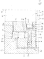
- FIG Figure 2 A first exemplary embodiment for such a ventilation path, including end position damping for the movement of the cylinder piston 13, is shown in FIG Figure 2 shown, in which the components of the end position damping in the Figure 1 apparent left cylinder cover 12 are arranged.
- a control valve 21 is arranged in the cylinder cover 12, in the piston chamber 22 of which a control piston 23 is arranged displaceably.
- the control piston On one side, the control piston has a shoulder 24 as an end stop for its movement in the piston chamber 22.
- a control chamber 25 On the opposite side of the control piston 23, a control chamber 25 is arranged as part of the piston chamber 22, which is discussed below.
- a closing arrangement 26 is formed in the cylinder cover 12, with a closing element 28 which is arranged displaceably in a displacement 27.
- a pressure chamber 29 is formed, which on the one hand has a line connection 30 to the connecting line 19 formed in the damping pin 17 connected.
- the pressure chamber 29 is also connected to the by means of a connecting bore 31 Control chamber 25 of the control valve 21 connected, wherein this connecting bore 31 can be closed in a corresponding position of the closing element 28 by means of a closing projection 32 formed on the closing element 28 and a sealing region 33 formed thereon.
- control piston 23 of the control valve 21 is biased by means of a spring 34 arranged in the control chamber 25, wherein in its neutral position the control piston 23 is biased by the spring 34 into its end position with a stop of the shoulder 24 against the wall of the piston chamber 22 is.
- the closing element 28 is also biased into its closed position, which is still to be explained, by means of a spring 35 arranged in the pressure chamber 29 of the closing arrangement 26, in which the closing extension 32 of the closing element 28 releases the connecting bore 31 between the pressure chamber 29 and the control chamber 25 of the control valve 21.
- a ventilation duct consisting of three sections 36a, b, c is formed in the cylinder cover 12.
- the first section 36a leads from the damping space 20 into the displacement 27 of the closing arrangement 26, the closing element 28 in the starting position closing the displacement 27 against the first section 36a of the ventilation duct with a sealing region 38 formed on it due to the pretension of the spring 35.
- a second section 36b of the ventilation duct then leads from the displacement 27 to the ventilation space 37 of the control valve 21 arranged opposite the control chamber 25 in such a way that the outlet of the second section 36b from the displacement 27 of the locking arrangement 26 can be released from the locking element 28 in its displaced position.
- a third section 36c of the ventilation channel leads from the ventilation space 37 of the control valve 21 to the connecting line 19 in the damping pin 17 such that in the initial position the outlet of the third section 36c of the Vent channel from the vent space 37 covered by the control piston 23, but can be released by this in the displaced position.
- the venting pressure below the working pressure is initially via the line connection 30 in the pressure chamber 29 of the locking arrangement 26 and via the between the Pressure chamber 29 and the control chamber 25 of the control valve 21 existing connection bore 31 also in the control chamber 25 of the control valve 21.
- the ventilation pressure present in the pressure chamber 29 as well as in the control chamber 25 initially ensures that the closing element 28 is supported in a pressure-balanced manner because the ventilation pressure is also present on the closing side of the closing arrangement 26 defined by the sealing region 38 of the closing element 28 via the first section 36a of the ventilation channel .
- the spring 35 ensures the closed position of the closing element 28 with respect to the first section 36a of the ventilation channel.
- a deliberately missing seal of the control piston 23 against the third section 36c of the venting channel ensures that the venting pressure in the third section 36c of the venting channel connected to the connecting line 19 is also present Venting space 37 of the control valve is present, the control piston 23 being held in the defined starting position by the spring 34 acting on it.
- damping pressure in the damping space 20 increases.
- the start of damping is characterized by this increase in pressure.
- the venting pressure still present in the system at the moment the damping begins is present in particular in the control chamber 25 of the control valve 21 and also in the pressure chamber 29 of the closing arrangement 26.
- the pressure rising in the damping chamber 20 from the start of damping now leads via the first section 36a of the venting channel to pressurizing the closing element 28, so that the closing element is moved into its closed position, in which its closing extension 32 with sealing area 33 connects the connecting bore 31 to the control chamber 25
- Control valve 21 closes.
- the ventilation pressure present in the control chamber 25 at the time of the pressure increase in the damping chamber 20 is fixed as the control pressure for the control piston 23.
- the closing movement of the closing element 28 releases the second section 36b of the ventilation channel leading away from the displacement 27 of the closing arrangement 26, so that the air displaced with increasing pressure from the damping chamber 20 via the sections 36a, b of the ventilation channel into the ventilation chamber 37 of the control valve 21 occurs and also causes a pressure increase here. If this damping pressure present in the ventilation space 37, due to the increasing pressure in the damping space 20, exceeds the ventilation pressure enclosed in the control chamber 25 of the control valve 21, the control piston 23 is displaced into the control chamber 25 and thereby gives the third section 36c of the ventilation chamber 37 Vent channel free, so that the air displaced from the damping space 20 can flow out via the now released sections 36a, b, c of the vent channel into the connecting line 19. So is a pressure controlled and thus damping discharge of the air displaced from the damping space 20.
- the arrangement of the spring 34 biasing the control piston 23 can be dispensed with, for example, when a check valve with a passage direction directed from the control valve 21 to the connecting line 19 is switched on in the third section 36c of the ventilation duct.
- a check valve with a passage direction directed from the control valve 21 to the connecting line 19 is switched on in the third section 36c of the ventilation duct.
- the illustrated embodiment differs from the previously described embodiment in that the control valve 21 and the locking arrangement 26 are arranged in the cylinder cover 12 in a modified manner, and in that the line connection 30 is connected directly to the damping space 20 between the pressure chamber 29 of the locking arrangement 26 and thus also the control chamber 25 of the control valve 21 In this case, the ventilation duct is no longer guided over the closing arrangement, rather only a section 36a of the ventilation duct leading from the damping chamber 20 to the ventilation chamber 37 of the control valve 21 and a section 36c of the damping duct leading from the ventilation chamber 37 to the connecting line 19 are provided.
- the locking arrangement 26 arranged in the cylinder cover 12 is connected to the damping space 20 via a feed line 50.
- the closing element 28 is guided in the displacement 27 of the closing arrangement 26 in a non-sealed manner so that the air present in the damping space 20 can first flow past the closing element 28 into a line section 45 connected to the control chamber 25 of the control valve 21.
- the closed position of the closing element 28 at the end of the control chamber 25 against the damping chamber 20 is due to a sealing seat 46 between the displacement 27 of the locking arrangement 26 and the line section 45 formed, on which the closing element 28 is seated in its closed position with the sealing region 38a formed on it.
- the line section 45 is connected to the section 36c of the venting channel, whereby in the area of the line section 45 between the section 36c of the venting channel and the connection of the control chamber 25 of the control valve 21, a pressure piston 48 connected to the closing element 28 via a rod 47 seals is guided, which in turn is biased by a spring 35a into a position of the closing element 28, in which the closing element 28 is lifted from the sealing seat 46 and thus releases the flow path from the damping chamber 20 into the control chamber 25 of the control valve 21.
- the venting pressure in the damping chamber 20 at the beginning of the damping (arrow 40) is present on the one hand via the section 36a of the venting channel in the venting chamber 37 of the control valve 21.
- This venting pressure is also present via the feed line 50 and the open flow path in the closing arrangement 26, also in the displacement 27 of the closing arrangement 26, the line section 45 and also in the control chamber 25 of the control valve 21, so that both the control piston 23 and the closing element 28 are arranged in a pressure-balanced manner are.
- Control pistons 23 and closing element 28 are each held in a defined starting position by means of the corresponding springs 34 and 35a.
- the closing element 28 is again moved in contact with its sealing region 38a on the sealing seat 46. so that the ventilation pressure present in the control chamber 25 of the control valve 21 at the time of the start of damping is enclosed in the control chamber 25 and acts here as a fixed control pressure for the control piston 23.
- the pressure rising in the damping chamber 20 is also present in the ventilation chamber 37 of the control valve 21 via the section 36a of the ventilation channel, and as soon as the damping pressure exceeds the control pressure of the control valve 21 characterized by the ventilation pressure, the control piston 23 is moved into its position in which it Connection of section 36c of the ventilation channel is released, so that the air present in the damping space 20 can flow out into the connecting line 19 via the ventilation path 36a, 36c.
Landscapes
- Engineering & Computer Science (AREA)
- Physics & Mathematics (AREA)
- Fluid Mechanics (AREA)
- Mechanical Engineering (AREA)
- General Engineering & Computer Science (AREA)
- Fluid-Damping Devices (AREA)
- Fluid-Pressure Circuits (AREA)
Claims (16)
- Vérin pneumatique (10) comportant un boîtier de vérin (11) et un piston de vérin (13) allant et venant dedans sous l'effet de pression et qui est sollicité respectivement dans son unique sens de mouvement par une conduite de raccordement (15) faisant alternativement office de conduite de pression et de conduite de purge d'air par une pression opérationnelle et refoule, sur sa face respectivement opposée, l'air présent dans l'espace intérieur du vérin (16) avec une pression de purge d'air plus faible hors de l'espace intérieur du vérin (16), étant disposés, à au moins une extrémité de la voie du piston de vérin, un dispositif d'amortissement comportant une chambre d'amortissement (20) disposée dans l'espace intérieur de vérin (16) et limitée par le piston de vérin (13) en mouvement et qui, pour l'amortissement de la position finale du piston de vérin (13), est purgée sur une voie de purge d'air grâce à une soupape de commande (21) qui y est incorporée, la soupape de commande à contrôle pneumatique (21) comprenant un piston de commande (23) dont le côté de commande détourné de la voie de purge d'air est sollicité par une pression pneumatique intervenant dans une chambre de commande (25),a) la chambre de commande (25) de la soupape de commande (21) étant connectée au moyen d'une liaison par canalisation (30 ; 50, 45) à une zone se trouvant sous pression de purge d'air du dispositif d'amortissement etb) un dispositif de fermeture (26) à élément de fermeture contrôlé (28) étant intégré dans la liaison par canalisation (30 ; 50, 45),
caractérisé en ce que le dispositif de fermeture (26) est conçu pour que la liaison par canalisation (30 ; 50, 45) soit interrompue par un mouvement contrôlé de l'élément de fermeture (28) au début de l'amortissement, de sorte que,
au moyen de l'élément de fermeture (28), la pression de purge d'air respectivement actuellement présente dans la chambre de commande (25) de la soupape de commande (21) au début de l'amortissement caractérisé par une hausse de pression dans la chambre d'amortissement (20)b1) peut être renfermée dans la chambre de commande (25) etb2) agit en tant que pression de commande ainsi fixée sur le piston de commande (23) de la soupape de commande (21) etb3) établit le moment d'ouverture de la soupape de commande (21) pour libérer la voie de purge d'air. - Vérin pneumatique selon la revendication 1, qui est conçu pour que le mouvement de l'élément de fermeture soit contrôlé électriquement en fonction d'un signal de commande capté lors du début de l'amortissement.
- Vérin pneumatique selon la revendication 1, qui est conçu pour que le mouvement de l'élément de fermeture soit contrôlé par le mouvement relatif du piston de vérin par rapport au boîtier de vérin.
- Vérin pneumatique selon la revendication 1, qui est conçu pour que le mouvement de l'élément de fermeture (28) du dispositif de fermeture (26) dans la chambre de commande (25) de la soupape de commande (21) soit contrôlé par système pneumatique par la pression augmentant dans la chambre d'amortissement (20) au début de l'amortissement.
- Vérin pneumatique selon la revendication 4, caractérisé en ce que l'élément de fermeture (28) est réalisé sous forme d'un élément piston mobile en longueur dans une cylindrée (27), dans lequel, au niveau du côté pression détourné du sens de mouvement de fermeture de l'élément de fermeture (28),
la pression respectivement présente dans la chambre d'amortissement (20) est respectivement appliquée et la chambre de pression (29) se trouvant sur la face opposée de l'élément de fermeture (28) est connectée à la chambre de commande (25) de la soupape de commande (21). - Vérin pneumatique selon la revendication 4 ou 5, caractérisé en ce que, au niveau de la butée terminale du piston de vérin (13), un tourillon d'amortissement (17) s'étendant dans le sens axial dans la chambre intérieure de piston (16) est disposé avec la conduite de raccordement (19) en traversant celle-ci et le piston de vérin (13) est réalisé avec un évidement (18) recevant le tourillon d'amortissement (17).
- Vérin pneumatique selon une des revendications 4 à 6, caractérisé en ce que la soupape de commande (21) et le dispositif de fermeture (26) sont disposés dans le couvercle de vérin (12) du vérin pneumatique (10).
- Vérin pneumatique selon la revendication 7, caractérisé en ce que la liaison par canalisation entre la chambre de commande (25) de la soupape de commande (21) et la zone présentant la pression de purge d'air du dispositif d'amortissement est constituée par un canal de liaison (30) s'étendant entre la chambre de pression (29) connectée à la chambre de commande (25) du dispositif de fermeture (26) et la conduite de raccordement (19), et que la voie de purge d'air est composée d'un canal de purge d'air (36a, b, c) partant de la chambre d'amortissement (20) et s'étendant en passant par la cylindrée côté pression (27) du dispositif de fermeture et par la soupape de commande (21) jusqu'à la conduite de raccordement (19) et qui est barré avant le début de l'amortissement par le dispositif de fermeture (26) vis-à-vis de la chambre d'amortissement (20).
- Vérin pneumatique selon la revendication 8, caractérisé en ce que, dans la section (36c) s'étendant entre la soupape de commande (21) et la conduite de raccordement (19) de la voie de purge d'air, une soupape antiretour ayant un sens de passage dirigé par la soupape de commande (21) vers la conduite de raccordement (19) est intégrée.
- Vérin pneumatique selon la revendication 7, caractérisé en ce que la liaison par canalisation entre la chambre de commande (25) de la soupape de commande (21) et la chambre d'amortissement (20) présentant la pression de purge d'air avant le début de l'amortissement est constituée par un canal de liaison (45,50) recevant le dispositif de fermeture (26), et que la voie de purge d'air est composée d'un canal de purge d'air (36a, c) partant de la chambre d'amortissement (20) et passant par la soupape de commande (21) pour aller jusqu'à la conduite de raccordement (19).
- Vérin pneumatique selon une des revendications 4 à 6, caractérisé en ce que la soupape de commande (21) et le dispositif de fermeture (26) sont disposés dans le piston de vérin (13) du vérin pneumatique (10).
- Vérin pneumatique selon la revendication 11, caractérisé en ce que la liaison par canalisation entre la chambre de commande (25) de la soupape de commande (21) et la zone présentant la pression de purge d'air du dispositif d'amortissement est constituée par un canal de liaison (30) s'étendant entre la chambre de pression (29) connectée à la chambre de commande (25) du dispositif de fermeture (26) et l'évidement (18) du piston de vérin (13), et que la voie de purge d'air est composée d'un canal de purge d'air (36a, b, c) partant de la chambre d'amortissement (20) et passant par la cylindrée côté pression (27) du dispositif de fermeture (26) et par la soupape de commande (21) jusque dans l'évidement (18) du piston de vérin (13) et qui est barré avant le
début de l'amortissement par le dispositif de fermeture (26) vis-à-vis de la chambre d'amortissement (20). - Vérin pneumatique selon la revendication 11, caractérisé en ce que la liaison par canalisation entre la chambre de commande (25) de la soupape de commande (21) et la chambre d'amortissement (20) présentant la pression de purge d'air avant le début de l'amortissement est constituée par un canal de liaison (45,50) recevant le dispositif de fermeture (26), et que la voie de purge d'air est composée d'un canal de purge d'air (36a, c) partant de la chambre d'amortissement (20) et passant par la soupape de commande (21) pour aller jusqu'à l'évidement (18) du piston de vérin (13).
- Vérin pneumatique selon une des revendications 1 à 13, caractérisé en ce que le piston de commande (23) de la soupape de commande (21) est disposé sans étanchéité entre la voie de purge d'air (36a, b, c) dans le boîtier de soupape de la soupape de commande (21).
- Vérin pneumatique selon une des revendications 1 à 14, caractérisé en ce que le piston de commande (23) de la soupape de commande (21) et l'élément de fermeture (28) du dispositif de fermeture (26) sont respectivement maintenus dans une position de départ définie avant le début de l'amortissement respectivement par des dispositifs à ressort associés.
- Vérin pneumatique selon une des revendications 1 à 15, caractérisé en ce que le piston de commande (23) de la soupape de commande (21) et l'élément de fermeture (28) du dispositif de fermeture (26) sont disposés respectivement avec un équilibrage de pression par la disposition de liaisons par canalisation supplémentaires avant le début de l'amortissement.
Applications Claiming Priority (1)
| Application Number | Priority Date | Filing Date | Title |
|---|---|---|---|
| DE102011051400A DE102011051400B3 (de) | 2011-06-28 | 2011-06-28 | Pneumatikzylinder mit selbstjustierender Endlagendämpfung |
Publications (3)
| Publication Number | Publication Date |
|---|---|
| EP2541073A2 EP2541073A2 (fr) | 2013-01-02 |
| EP2541073A3 EP2541073A3 (fr) | 2016-11-02 |
| EP2541073B1 true EP2541073B1 (fr) | 2020-08-05 |
Family
ID=46083178
Family Applications (1)
| Application Number | Title | Priority Date | Filing Date |
|---|---|---|---|
| EP12171413.3A Active EP2541073B1 (fr) | 2011-06-28 | 2012-06-11 | Cylindre pneumatique avec amortissement de fin de course à auto-ajustage |
Country Status (3)
| Country | Link |
|---|---|
| US (1) | US9080584B2 (fr) |
| EP (1) | EP2541073B1 (fr) |
| DE (1) | DE102011051400B3 (fr) |
Families Citing this family (2)
| Publication number | Priority date | Publication date | Assignee | Title |
|---|---|---|---|---|
| WO2016205087A1 (fr) * | 2015-06-15 | 2016-12-22 | Board Of Supervisors Of Louisiana State University And Agricultural And Mechanical College | Granulés en fibres cellulosiques thermoplastiques utiles comme matériaux de remplissage pour gazon artificiel |
| CN109084967A (zh) * | 2017-06-14 | 2018-12-25 | 鸿富锦精密电子(天津)有限公司 | 推拉测试装置 |
Family Cites Families (9)
| Publication number | Priority date | Publication date | Assignee | Title |
|---|---|---|---|---|
| AT213677B (de) * | 1958-07-23 | 1961-02-27 | Hydraulik Rochlitz Veb | Hydraulische Dämpfungseinrichtung an geradlinigen Kolbengetrieben |
| GB1351958A (en) | 1971-09-14 | 1974-05-15 | Martonair Ltd | Pneumatic actuators |
| DE2326417C3 (de) * | 1973-05-24 | 1980-01-10 | Maschinenfabrik Glueckauf Beukenberg Gmbh & Co, 4650 Gelsenkirchen | Hydraulik-Zylinder mit Endlagendämpfung |
| JP2598210B2 (ja) * | 1992-12-01 | 1997-04-09 | エスエムシー株式会社 | シリンダ装置 |
| FR2781016B1 (fr) * | 1998-07-08 | 2002-03-08 | Aro | Verin a precourse d'approche et course de travail, pour la manoeuvre d'un outil |
| US6612410B1 (en) * | 2001-10-17 | 2003-09-02 | Yevgeny Antonovsky | High frequency shock absorber and accelerator |
| DE102006041707B4 (de) * | 2006-05-10 | 2009-01-02 | Tünkers Maschinenbau Gmbh | Kolben-Zylinder-Einheit (Arbeitszylinder) zum Spannen, und/oder Pressen, und/oder Fügen, und/oder Stanzen, und/oder Prägen, und/oder Lochen und/oder Schweißen, zum Beispiel unter Zwischenschaltung einer Kniehebelgelenkanordnung |
| EP1998054B1 (fr) | 2007-05-24 | 2014-08-13 | Parker Origa Holding AG | Cylindre pneumatique avec amortissement à réglage automatique en position finale et procédé |
| WO2010096737A1 (fr) * | 2009-02-23 | 2010-08-26 | Albrecht David E | Clapets déphaseurs pour cylindre |
-
2011
- 2011-06-28 DE DE102011051400A patent/DE102011051400B3/de active Active
-
2012
- 2012-06-11 EP EP12171413.3A patent/EP2541073B1/fr active Active
- 2012-06-26 US US13/533,333 patent/US9080584B2/en active Active
Non-Patent Citations (1)
| Title |
|---|
| None * |
Also Published As
| Publication number | Publication date |
|---|---|
| DE102011051400B3 (de) | 2012-06-06 |
| EP2541073A2 (fr) | 2013-01-02 |
| US20130001031A1 (en) | 2013-01-03 |
| US9080584B2 (en) | 2015-07-14 |
| EP2541073A3 (fr) | 2016-11-02 |
Similar Documents
| Publication | Publication Date | Title |
|---|---|---|
| EP3080461B1 (fr) | Valve | |
| DE3434033A1 (de) | Pneumatischer zylinder mit daempfungsmechanik und verfahren zum daempfen des pneumatischen zylinders | |
| EP1860328A1 (fr) | Dispositif de contrôle de vérin pneumatique à double effet | |
| DE3323363A1 (de) | Vorgesteuertes druckreduzierventil | |
| EP0829668B1 (fr) | Vanne électromagnétique | |
| DE102015109474A1 (de) | Umschaltventil und Pleuel mit einem Umschaltventil | |
| DE102014119592B4 (de) | Ventil | |
| EP1631746B1 (fr) | Entrainement hydraulique servant a deplacer un actionneur | |
| EP2541073B1 (fr) | Cylindre pneumatique avec amortissement de fin de course à auto-ajustage | |
| DE19637291C2 (de) | Vorrichtung zur Endlagendämpfung | |
| DE102004023255B3 (de) | Druckminderventil | |
| EP2951067B1 (fr) | Vérin hydraulique d'actionnement d'un frein électromagnétique sur rails | |
| DE1813145C2 (de) | Luftverteiler für eine druckluftbetriebene hydropneumatische Pumpe zur Förderung von Druckflüssigkeit | |
| DE2909504C2 (fr) | ||
| DE102006035175B4 (de) | Pneumatikventil mit schneller Rückstellung | |
| DE10010690A1 (de) | Ventil | |
| DE4421357A1 (de) | Pneumatisches Wegeventil | |
| DE102018201655B4 (de) | Beschleunigungsventil für selbsttätige Druckluftbremsen von Schienenfahrzeugen | |
| EP2697105B1 (fr) | Servofrein à compensation de pression dépendant de la position | |
| DE10255524B4 (de) | Elektromagnetisches 3/2-Wegesitzventil mit A-Kompensation | |
| DE102008060650A1 (de) | Ventil mit Endlagen-Dämpfungseinrichtung | |
| DE2915505C2 (fr) | ||
| DE10147299A1 (de) | Vorrichtung zur Steuerung eines Öffnungsquerschnitts in einem Verbrennungszylinder einer Brennkraftmaschine | |
| DE29609485U1 (de) | Vorrichtung zur Verzögerung einer bewegten Masse | |
| DE2155706C3 (de) | Lastabhängig arbeitendes Bremsdrucksteuerventil für eine hydraulische Fahrzeugbremsanlage |
Legal Events
| Date | Code | Title | Description |
|---|---|---|---|
| PUAI | Public reference made under article 153(3) epc to a published international application that has entered the european phase |
Free format text: ORIGINAL CODE: 0009012 |
|
| AK | Designated contracting states |
Kind code of ref document: A2 Designated state(s): AL AT BE BG CH CY CZ DE DK EE ES FI FR GB GR HR HU IE IS IT LI LT LU LV MC MK MT NL NO PL PT RO RS SE SI SK SM TR |
|
| AX | Request for extension of the european patent |
Extension state: BA ME |
|
| PUAL | Search report despatched |
Free format text: ORIGINAL CODE: 0009013 |
|
| AK | Designated contracting states |
Kind code of ref document: A3 Designated state(s): AL AT BE BG CH CY CZ DE DK EE ES FI FR GB GR HR HU IE IS IT LI LT LU LV MC MK MT NL NO PL PT RO RS SE SI SK SM TR |
|
| AX | Request for extension of the european patent |
Extension state: BA ME |
|
| RIC1 | Information provided on ipc code assigned before grant |
Ipc: F15B 15/22 20060101ALI20160926BHEP Ipc: F15B 15/20 20060101AFI20160926BHEP |
|
| STAA | Information on the status of an ep patent application or granted ep patent |
Free format text: STATUS: REQUEST FOR EXAMINATION WAS MADE |
|
| 17P | Request for examination filed |
Effective date: 20170428 |
|
| RBV | Designated contracting states (corrected) |
Designated state(s): AL AT BE BG CH CY CZ DE DK EE ES FI FR GB GR HR HU IE IS IT LI LT LU LV MC MK MT NL NO PL PT RO RS SE SI SK SM TR |
|
| STAA | Information on the status of an ep patent application or granted ep patent |
Free format text: STATUS: EXAMINATION IS IN PROGRESS |
|
| 17Q | First examination report despatched |
Effective date: 20180314 |
|
| GRAP | Despatch of communication of intention to grant a patent |
Free format text: ORIGINAL CODE: EPIDOSNIGR1 |
|
| STAA | Information on the status of an ep patent application or granted ep patent |
Free format text: STATUS: GRANT OF PATENT IS INTENDED |
|
| INTG | Intention to grant announced |
Effective date: 20200325 |
|
| GRAS | Grant fee paid |
Free format text: ORIGINAL CODE: EPIDOSNIGR3 |
|
| GRAA | (expected) grant |
Free format text: ORIGINAL CODE: 0009210 |
|
| STAA | Information on the status of an ep patent application or granted ep patent |
Free format text: STATUS: THE PATENT HAS BEEN GRANTED |
|
| AK | Designated contracting states |
Kind code of ref document: B1 Designated state(s): AL AT BE BG CH CY CZ DE DK EE ES FI FR GB GR HR HU IE IS IT LI LT LU LV MC MK MT NL NO PL PT RO RS SE SI SK SM TR |
|
| REG | Reference to a national code |
Ref country code: GB Ref legal event code: FG4D Free format text: NOT ENGLISH |
|
| REG | Reference to a national code |
Ref country code: CH Ref legal event code: EP |
|
| REG | Reference to a national code |
Ref country code: AT Ref legal event code: REF Ref document number: 1299097 Country of ref document: AT Kind code of ref document: T Effective date: 20200815 |
|
| REG | Reference to a national code |
Ref country code: DE Ref legal event code: R096 Ref document number: 502012016258 Country of ref document: DE |
|
| REG | Reference to a national code |
Ref country code: IE Ref legal event code: FG4D Free format text: LANGUAGE OF EP DOCUMENT: GERMAN |
|
| REG | Reference to a national code |
Ref country code: LT Ref legal event code: MG4D |
|
| REG | Reference to a national code |
Ref country code: NL Ref legal event code: MP Effective date: 20200805 |
|
| PG25 | Lapsed in a contracting state [announced via postgrant information from national office to epo] |
Ref country code: PT Free format text: LAPSE BECAUSE OF FAILURE TO SUBMIT A TRANSLATION OF THE DESCRIPTION OR TO PAY THE FEE WITHIN THE PRESCRIBED TIME-LIMIT Effective date: 20201207 Ref country code: GR Free format text: LAPSE BECAUSE OF FAILURE TO SUBMIT A TRANSLATION OF THE DESCRIPTION OR TO PAY THE FEE WITHIN THE PRESCRIBED TIME-LIMIT Effective date: 20201106 Ref country code: FI Free format text: LAPSE BECAUSE OF FAILURE TO SUBMIT A TRANSLATION OF THE DESCRIPTION OR TO PAY THE FEE WITHIN THE PRESCRIBED TIME-LIMIT Effective date: 20200805 Ref country code: SE Free format text: LAPSE BECAUSE OF FAILURE TO SUBMIT A TRANSLATION OF THE DESCRIPTION OR TO PAY THE FEE WITHIN THE PRESCRIBED TIME-LIMIT Effective date: 20200805 Ref country code: LT Free format text: LAPSE BECAUSE OF FAILURE TO SUBMIT A TRANSLATION OF THE DESCRIPTION OR TO PAY THE FEE WITHIN THE PRESCRIBED TIME-LIMIT Effective date: 20200805 Ref country code: HR Free format text: LAPSE BECAUSE OF FAILURE TO SUBMIT A TRANSLATION OF THE DESCRIPTION OR TO PAY THE FEE WITHIN THE PRESCRIBED TIME-LIMIT Effective date: 20200805 Ref country code: NO Free format text: LAPSE BECAUSE OF FAILURE TO SUBMIT A TRANSLATION OF THE DESCRIPTION OR TO PAY THE FEE WITHIN THE PRESCRIBED TIME-LIMIT Effective date: 20201105 Ref country code: ES Free format text: LAPSE BECAUSE OF FAILURE TO SUBMIT A TRANSLATION OF THE DESCRIPTION OR TO PAY THE FEE WITHIN THE PRESCRIBED TIME-LIMIT Effective date: 20200805 Ref country code: BG Free format text: LAPSE BECAUSE OF FAILURE TO SUBMIT A TRANSLATION OF THE DESCRIPTION OR TO PAY THE FEE WITHIN THE PRESCRIBED TIME-LIMIT Effective date: 20201105 |
|
| PG25 | Lapsed in a contracting state [announced via postgrant information from national office to epo] |
Ref country code: RS Free format text: LAPSE BECAUSE OF FAILURE TO SUBMIT A TRANSLATION OF THE DESCRIPTION OR TO PAY THE FEE WITHIN THE PRESCRIBED TIME-LIMIT Effective date: 20200805 Ref country code: NL Free format text: LAPSE BECAUSE OF FAILURE TO SUBMIT A TRANSLATION OF THE DESCRIPTION OR TO PAY THE FEE WITHIN THE PRESCRIBED TIME-LIMIT Effective date: 20200805 Ref country code: LV Free format text: LAPSE BECAUSE OF FAILURE TO SUBMIT A TRANSLATION OF THE DESCRIPTION OR TO PAY THE FEE WITHIN THE PRESCRIBED TIME-LIMIT Effective date: 20200805 Ref country code: PL Free format text: LAPSE BECAUSE OF FAILURE TO SUBMIT A TRANSLATION OF THE DESCRIPTION OR TO PAY THE FEE WITHIN THE PRESCRIBED TIME-LIMIT Effective date: 20200805 Ref country code: IS Free format text: LAPSE BECAUSE OF FAILURE TO SUBMIT A TRANSLATION OF THE DESCRIPTION OR TO PAY THE FEE WITHIN THE PRESCRIBED TIME-LIMIT Effective date: 20201205 |
|
| PG25 | Lapsed in a contracting state [announced via postgrant information from national office to epo] |
Ref country code: EE Free format text: LAPSE BECAUSE OF FAILURE TO SUBMIT A TRANSLATION OF THE DESCRIPTION OR TO PAY THE FEE WITHIN THE PRESCRIBED TIME-LIMIT Effective date: 20200805 Ref country code: DK Free format text: LAPSE BECAUSE OF FAILURE TO SUBMIT A TRANSLATION OF THE DESCRIPTION OR TO PAY THE FEE WITHIN THE PRESCRIBED TIME-LIMIT Effective date: 20200805 Ref country code: CZ Free format text: LAPSE BECAUSE OF FAILURE TO SUBMIT A TRANSLATION OF THE DESCRIPTION OR TO PAY THE FEE WITHIN THE PRESCRIBED TIME-LIMIT Effective date: 20200805 Ref country code: SM Free format text: LAPSE BECAUSE OF FAILURE TO SUBMIT A TRANSLATION OF THE DESCRIPTION OR TO PAY THE FEE WITHIN THE PRESCRIBED TIME-LIMIT Effective date: 20200805 Ref country code: RO Free format text: LAPSE BECAUSE OF FAILURE TO SUBMIT A TRANSLATION OF THE DESCRIPTION OR TO PAY THE FEE WITHIN THE PRESCRIBED TIME-LIMIT Effective date: 20200805 |
|
| REG | Reference to a national code |
Ref country code: DE Ref legal event code: R097 Ref document number: 502012016258 Country of ref document: DE |
|
| PG25 | Lapsed in a contracting state [announced via postgrant information from national office to epo] |
Ref country code: AL Free format text: LAPSE BECAUSE OF FAILURE TO SUBMIT A TRANSLATION OF THE DESCRIPTION OR TO PAY THE FEE WITHIN THE PRESCRIBED TIME-LIMIT Effective date: 20200805 |
|
| PLBE | No opposition filed within time limit |
Free format text: ORIGINAL CODE: 0009261 |
|
| STAA | Information on the status of an ep patent application or granted ep patent |
Free format text: STATUS: NO OPPOSITION FILED WITHIN TIME LIMIT |
|
| PG25 | Lapsed in a contracting state [announced via postgrant information from national office to epo] |
Ref country code: SK Free format text: LAPSE BECAUSE OF FAILURE TO SUBMIT A TRANSLATION OF THE DESCRIPTION OR TO PAY THE FEE WITHIN THE PRESCRIBED TIME-LIMIT Effective date: 20200805 |
|
| 26N | No opposition filed |
Effective date: 20210507 |
|
| PG25 | Lapsed in a contracting state [announced via postgrant information from national office to epo] |
Ref country code: SI Free format text: LAPSE BECAUSE OF FAILURE TO SUBMIT A TRANSLATION OF THE DESCRIPTION OR TO PAY THE FEE WITHIN THE PRESCRIBED TIME-LIMIT Effective date: 20200805 |
|
| PG25 | Lapsed in a contracting state [announced via postgrant information from national office to epo] |
Ref country code: MC Free format text: LAPSE BECAUSE OF FAILURE TO SUBMIT A TRANSLATION OF THE DESCRIPTION OR TO PAY THE FEE WITHIN THE PRESCRIBED TIME-LIMIT Effective date: 20200805 |
|
| REG | Reference to a national code |
Ref country code: CH Ref legal event code: PL |
|
| REG | Reference to a national code |
Ref country code: BE Ref legal event code: MM Effective date: 20210630 |
|
| PG25 | Lapsed in a contracting state [announced via postgrant information from national office to epo] |
Ref country code: LU Free format text: LAPSE BECAUSE OF NON-PAYMENT OF DUE FEES Effective date: 20210611 |
|
| PG25 | Lapsed in a contracting state [announced via postgrant information from national office to epo] |
Ref country code: LI Free format text: LAPSE BECAUSE OF NON-PAYMENT OF DUE FEES Effective date: 20210630 Ref country code: IE Free format text: LAPSE BECAUSE OF NON-PAYMENT OF DUE FEES Effective date: 20210611 Ref country code: CH Free format text: LAPSE BECAUSE OF NON-PAYMENT OF DUE FEES Effective date: 20210630 |
|
| PG25 | Lapsed in a contracting state [announced via postgrant information from national office to epo] |
Ref country code: BE Free format text: LAPSE BECAUSE OF NON-PAYMENT OF DUE FEES Effective date: 20210630 |
|
| REG | Reference to a national code |
Ref country code: AT Ref legal event code: MM01 Ref document number: 1299097 Country of ref document: AT Kind code of ref document: T Effective date: 20210611 |
|
| PG25 | Lapsed in a contracting state [announced via postgrant information from national office to epo] |
Ref country code: AT Free format text: LAPSE BECAUSE OF NON-PAYMENT OF DUE FEES Effective date: 20210611 |
|
| PG25 | Lapsed in a contracting state [announced via postgrant information from national office to epo] |
Ref country code: HU Free format text: LAPSE BECAUSE OF FAILURE TO SUBMIT A TRANSLATION OF THE DESCRIPTION OR TO PAY THE FEE WITHIN THE PRESCRIBED TIME-LIMIT; INVALID AB INITIO Effective date: 20120611 Ref country code: CY Free format text: LAPSE BECAUSE OF FAILURE TO SUBMIT A TRANSLATION OF THE DESCRIPTION OR TO PAY THE FEE WITHIN THE PRESCRIBED TIME-LIMIT Effective date: 20200805 |
|
| P01 | Opt-out of the competence of the unified patent court (upc) registered |
Effective date: 20230524 |
|
| PGFP | Annual fee paid to national office [announced via postgrant information from national office to epo] |
Ref country code: IT Payment date: 20230620 Year of fee payment: 12 |
|
| PG25 | Lapsed in a contracting state [announced via postgrant information from national office to epo] |
Ref country code: MK Free format text: LAPSE BECAUSE OF FAILURE TO SUBMIT A TRANSLATION OF THE DESCRIPTION OR TO PAY THE FEE WITHIN THE PRESCRIBED TIME-LIMIT Effective date: 20200805 |
|
| PG25 | Lapsed in a contracting state [announced via postgrant information from national office to epo] |
Ref country code: TR Free format text: LAPSE BECAUSE OF FAILURE TO SUBMIT A TRANSLATION OF THE DESCRIPTION OR TO PAY THE FEE WITHIN THE PRESCRIBED TIME-LIMIT Effective date: 20200805 |
|
| PGFP | Annual fee paid to national office [announced via postgrant information from national office to epo] |
Ref country code: GB Payment date: 20240627 Year of fee payment: 13 |
|
| PGFP | Annual fee paid to national office [announced via postgrant information from national office to epo] |
Ref country code: DE Payment date: 20240627 Year of fee payment: 13 |
|
| PGFP | Annual fee paid to national office [announced via postgrant information from national office to epo] |
Ref country code: FR Payment date: 20240625 Year of fee payment: 13 |