EP2540589A2 - Verfahren und Steuereinrichtung zur Steuerung oder Regelung von Fahrzeugsystemen - Google Patents
Verfahren und Steuereinrichtung zur Steuerung oder Regelung von Fahrzeugsystemen Download PDFInfo
- Publication number
- EP2540589A2 EP2540589A2 EP12002413A EP12002413A EP2540589A2 EP 2540589 A2 EP2540589 A2 EP 2540589A2 EP 12002413 A EP12002413 A EP 12002413A EP 12002413 A EP12002413 A EP 12002413A EP 2540589 A2 EP2540589 A2 EP 2540589A2
- Authority
- EP
- European Patent Office
- Prior art keywords
- vehicle
- delta
- distance
- front vehicle
- time duration
- Prior art date
- Legal status (The legal status is an assumption and is not a legal conclusion. Google has not performed a legal analysis and makes no representation as to the accuracy of the status listed.)
- Granted
Links
Images

Classifications
-
- B—PERFORMING OPERATIONS; TRANSPORTING
- B60—VEHICLES IN GENERAL
- B60W—CONJOINT CONTROL OF VEHICLE SUB-UNITS OF DIFFERENT TYPE OR DIFFERENT FUNCTION; CONTROL SYSTEMS SPECIALLY ADAPTED FOR HYBRID VEHICLES; ROAD VEHICLE DRIVE CONTROL SYSTEMS FOR PURPOSES NOT RELATED TO THE CONTROL OF A PARTICULAR SUB-UNIT
- B60W30/00—Purposes of road vehicle drive control systems not related to the control of a particular sub-unit, e.g. of systems using conjoint control of vehicle sub-units
- B60W30/14—Adaptive cruise control
- B60W30/16—Control of distance between vehicles, e.g. keeping a distance to preceding vehicle
-
- B—PERFORMING OPERATIONS; TRANSPORTING
- B60—VEHICLES IN GENERAL
- B60W—CONJOINT CONTROL OF VEHICLE SUB-UNITS OF DIFFERENT TYPE OR DIFFERENT FUNCTION; CONTROL SYSTEMS SPECIALLY ADAPTED FOR HYBRID VEHICLES; ROAD VEHICLE DRIVE CONTROL SYSTEMS FOR PURPOSES NOT RELATED TO THE CONTROL OF A PARTICULAR SUB-UNIT
- B60W10/00—Conjoint control of vehicle sub-units of different type or different function
- B60W10/04—Conjoint control of vehicle sub-units of different type or different function including control of propulsion units
- B60W10/06—Conjoint control of vehicle sub-units of different type or different function including control of propulsion units including control of combustion engines
-
- B—PERFORMING OPERATIONS; TRANSPORTING
- B60—VEHICLES IN GENERAL
- B60W—CONJOINT CONTROL OF VEHICLE SUB-UNITS OF DIFFERENT TYPE OR DIFFERENT FUNCTION; CONTROL SYSTEMS SPECIALLY ADAPTED FOR HYBRID VEHICLES; ROAD VEHICLE DRIVE CONTROL SYSTEMS FOR PURPOSES NOT RELATED TO THE CONTROL OF A PARTICULAR SUB-UNIT
- B60W10/00—Conjoint control of vehicle sub-units of different type or different function
- B60W10/04—Conjoint control of vehicle sub-units of different type or different function including control of propulsion units
- B60W10/08—Conjoint control of vehicle sub-units of different type or different function including control of propulsion units including control of electric propulsion units, e.g. motors or generators
-
- B—PERFORMING OPERATIONS; TRANSPORTING
- B60—VEHICLES IN GENERAL
- B60W—CONJOINT CONTROL OF VEHICLE SUB-UNITS OF DIFFERENT TYPE OR DIFFERENT FUNCTION; CONTROL SYSTEMS SPECIALLY ADAPTED FOR HYBRID VEHICLES; ROAD VEHICLE DRIVE CONTROL SYSTEMS FOR PURPOSES NOT RELATED TO THE CONTROL OF A PARTICULAR SUB-UNIT
- B60W10/00—Conjoint control of vehicle sub-units of different type or different function
- B60W10/30—Conjoint control of vehicle sub-units of different type or different function including control of auxiliary equipment, e.g. air-conditioning compressors or oil pumps
-
- B—PERFORMING OPERATIONS; TRANSPORTING
- B60—VEHICLES IN GENERAL
- B60W—CONJOINT CONTROL OF VEHICLE SUB-UNITS OF DIFFERENT TYPE OR DIFFERENT FUNCTION; CONTROL SYSTEMS SPECIALLY ADAPTED FOR HYBRID VEHICLES; ROAD VEHICLE DRIVE CONTROL SYSTEMS FOR PURPOSES NOT RELATED TO THE CONTROL OF A PARTICULAR SUB-UNIT
- B60W20/00—Control systems specially adapted for hybrid vehicles
-
- B—PERFORMING OPERATIONS; TRANSPORTING
- B60—VEHICLES IN GENERAL
- B60W—CONJOINT CONTROL OF VEHICLE SUB-UNITS OF DIFFERENT TYPE OR DIFFERENT FUNCTION; CONTROL SYSTEMS SPECIALLY ADAPTED FOR HYBRID VEHICLES; ROAD VEHICLE DRIVE CONTROL SYSTEMS FOR PURPOSES NOT RELATED TO THE CONTROL OF A PARTICULAR SUB-UNIT
- B60W30/00—Purposes of road vehicle drive control systems not related to the control of a particular sub-unit, e.g. of systems using conjoint control of vehicle sub-units
- B60W30/14—Adaptive cruise control
- B60W30/143—Speed control
-
- B—PERFORMING OPERATIONS; TRANSPORTING
- B60—VEHICLES IN GENERAL
- B60W—CONJOINT CONTROL OF VEHICLE SUB-UNITS OF DIFFERENT TYPE OR DIFFERENT FUNCTION; CONTROL SYSTEMS SPECIALLY ADAPTED FOR HYBRID VEHICLES; ROAD VEHICLE DRIVE CONTROL SYSTEMS FOR PURPOSES NOT RELATED TO THE CONTROL OF A PARTICULAR SUB-UNIT
- B60W30/00—Purposes of road vehicle drive control systems not related to the control of a particular sub-unit, e.g. of systems using conjoint control of vehicle sub-units
- B60W30/18—Propelling the vehicle
- B60W30/18009—Propelling the vehicle related to particular drive situations
- B60W30/18072—Coasting
-
- B—PERFORMING OPERATIONS; TRANSPORTING
- B60—VEHICLES IN GENERAL
- B60W—CONJOINT CONTROL OF VEHICLE SUB-UNITS OF DIFFERENT TYPE OR DIFFERENT FUNCTION; CONTROL SYSTEMS SPECIALLY ADAPTED FOR HYBRID VEHICLES; ROAD VEHICLE DRIVE CONTROL SYSTEMS FOR PURPOSES NOT RELATED TO THE CONTROL OF A PARTICULAR SUB-UNIT
- B60W30/00—Purposes of road vehicle drive control systems not related to the control of a particular sub-unit, e.g. of systems using conjoint control of vehicle sub-units
- B60W30/18—Propelling the vehicle
- B60W30/182—Selecting between different operative modes, e.g. comfort and performance modes
-
- B—PERFORMING OPERATIONS; TRANSPORTING
- B60—VEHICLES IN GENERAL
- B60W—CONJOINT CONTROL OF VEHICLE SUB-UNITS OF DIFFERENT TYPE OR DIFFERENT FUNCTION; CONTROL SYSTEMS SPECIALLY ADAPTED FOR HYBRID VEHICLES; ROAD VEHICLE DRIVE CONTROL SYSTEMS FOR PURPOSES NOT RELATED TO THE CONTROL OF A PARTICULAR SUB-UNIT
- B60W30/00—Purposes of road vehicle drive control systems not related to the control of a particular sub-unit, e.g. of systems using conjoint control of vehicle sub-units
- B60W30/18—Propelling the vehicle
- B60W30/184—Preventing damage resulting from overload or excessive wear of the driveline
- B60W30/186—Preventing damage resulting from overload or excessive wear of the driveline excessive wear or burn out of friction elements, e.g. clutches
-
- B—PERFORMING OPERATIONS; TRANSPORTING
- B60—VEHICLES IN GENERAL
- B60W—CONJOINT CONTROL OF VEHICLE SUB-UNITS OF DIFFERENT TYPE OR DIFFERENT FUNCTION; CONTROL SYSTEMS SPECIALLY ADAPTED FOR HYBRID VEHICLES; ROAD VEHICLE DRIVE CONTROL SYSTEMS FOR PURPOSES NOT RELATED TO THE CONTROL OF A PARTICULAR SUB-UNIT
- B60W50/00—Details of control systems for road vehicle drive control not related to the control of a particular sub-unit, e.g. process diagnostic or vehicle driver interfaces
- B60W50/0097—Predicting future conditions
-
- B—PERFORMING OPERATIONS; TRANSPORTING
- B60—VEHICLES IN GENERAL
- B60W—CONJOINT CONTROL OF VEHICLE SUB-UNITS OF DIFFERENT TYPE OR DIFFERENT FUNCTION; CONTROL SYSTEMS SPECIALLY ADAPTED FOR HYBRID VEHICLES; ROAD VEHICLE DRIVE CONTROL SYSTEMS FOR PURPOSES NOT RELATED TO THE CONTROL OF A PARTICULAR SUB-UNIT
- B60W30/00—Purposes of road vehicle drive control systems not related to the control of a particular sub-unit, e.g. of systems using conjoint control of vehicle sub-units
- B60W30/18—Propelling the vehicle
- B60W30/18009—Propelling the vehicle related to particular drive situations
- B60W30/18072—Coasting
- B60W2030/18081—With torque flow from driveshaft to engine, i.e. engine being driven by vehicle
-
- B—PERFORMING OPERATIONS; TRANSPORTING
- B60—VEHICLES IN GENERAL
- B60W—CONJOINT CONTROL OF VEHICLE SUB-UNITS OF DIFFERENT TYPE OR DIFFERENT FUNCTION; CONTROL SYSTEMS SPECIALLY ADAPTED FOR HYBRID VEHICLES; ROAD VEHICLE DRIVE CONTROL SYSTEMS FOR PURPOSES NOT RELATED TO THE CONTROL OF A PARTICULAR SUB-UNIT
- B60W30/00—Purposes of road vehicle drive control systems not related to the control of a particular sub-unit, e.g. of systems using conjoint control of vehicle sub-units
- B60W30/18—Propelling the vehicle
- B60W30/18009—Propelling the vehicle related to particular drive situations
- B60W30/18072—Coasting
- B60W2030/1809—Without torque flow between driveshaft and engine, e.g. with clutch disengaged or transmission in neutral
-
- B—PERFORMING OPERATIONS; TRANSPORTING
- B60—VEHICLES IN GENERAL
- B60W—CONJOINT CONTROL OF VEHICLE SUB-UNITS OF DIFFERENT TYPE OR DIFFERENT FUNCTION; CONTROL SYSTEMS SPECIALLY ADAPTED FOR HYBRID VEHICLES; ROAD VEHICLE DRIVE CONTROL SYSTEMS FOR PURPOSES NOT RELATED TO THE CONTROL OF A PARTICULAR SUB-UNIT
- B60W2520/00—Input parameters relating to overall vehicle dynamics
- B60W2520/10—Longitudinal speed
- B60W2520/105—Longitudinal acceleration
-
- B—PERFORMING OPERATIONS; TRANSPORTING
- B60—VEHICLES IN GENERAL
- B60W—CONJOINT CONTROL OF VEHICLE SUB-UNITS OF DIFFERENT TYPE OR DIFFERENT FUNCTION; CONTROL SYSTEMS SPECIALLY ADAPTED FOR HYBRID VEHICLES; ROAD VEHICLE DRIVE CONTROL SYSTEMS FOR PURPOSES NOT RELATED TO THE CONTROL OF A PARTICULAR SUB-UNIT
- B60W2554/00—Input parameters relating to objects
- B60W2554/80—Spatial relation or speed relative to objects
- B60W2554/801—Lateral distance
-
- B—PERFORMING OPERATIONS; TRANSPORTING
- B60—VEHICLES IN GENERAL
- B60W—CONJOINT CONTROL OF VEHICLE SUB-UNITS OF DIFFERENT TYPE OR DIFFERENT FUNCTION; CONTROL SYSTEMS SPECIALLY ADAPTED FOR HYBRID VEHICLES; ROAD VEHICLE DRIVE CONTROL SYSTEMS FOR PURPOSES NOT RELATED TO THE CONTROL OF A PARTICULAR SUB-UNIT
- B60W2554/00—Input parameters relating to objects
- B60W2554/80—Spatial relation or speed relative to objects
- B60W2554/804—Relative longitudinal speed
-
- B—PERFORMING OPERATIONS; TRANSPORTING
- B60—VEHICLES IN GENERAL
- B60W—CONJOINT CONTROL OF VEHICLE SUB-UNITS OF DIFFERENT TYPE OR DIFFERENT FUNCTION; CONTROL SYSTEMS SPECIALLY ADAPTED FOR HYBRID VEHICLES; ROAD VEHICLE DRIVE CONTROL SYSTEMS FOR PURPOSES NOT RELATED TO THE CONTROL OF A PARTICULAR SUB-UNIT
- B60W2556/00—Input parameters relating to data
- B60W2556/10—Historical data
-
- B—PERFORMING OPERATIONS; TRANSPORTING
- B60—VEHICLES IN GENERAL
- B60W—CONJOINT CONTROL OF VEHICLE SUB-UNITS OF DIFFERENT TYPE OR DIFFERENT FUNCTION; CONTROL SYSTEMS SPECIALLY ADAPTED FOR HYBRID VEHICLES; ROAD VEHICLE DRIVE CONTROL SYSTEMS FOR PURPOSES NOT RELATED TO THE CONTROL OF A PARTICULAR SUB-UNIT
- B60W2556/00—Input parameters relating to data
- B60W2556/45—External transmission of data to or from the vehicle
- B60W2556/50—External transmission of data to or from the vehicle of positioning data, e.g. GPS [Global Positioning System] data
-
- B—PERFORMING OPERATIONS; TRANSPORTING
- B60—VEHICLES IN GENERAL
- B60W—CONJOINT CONTROL OF VEHICLE SUB-UNITS OF DIFFERENT TYPE OR DIFFERENT FUNCTION; CONTROL SYSTEMS SPECIALLY ADAPTED FOR HYBRID VEHICLES; ROAD VEHICLE DRIVE CONTROL SYSTEMS FOR PURPOSES NOT RELATED TO THE CONTROL OF A PARTICULAR SUB-UNIT
- B60W2720/00—Output or target parameters relating to overall vehicle dynamics
- B60W2720/10—Longitudinal speed
- B60W2720/106—Longitudinal acceleration
-
- B—PERFORMING OPERATIONS; TRANSPORTING
- B60—VEHICLES IN GENERAL
- B60W—CONJOINT CONTROL OF VEHICLE SUB-UNITS OF DIFFERENT TYPE OR DIFFERENT FUNCTION; CONTROL SYSTEMS SPECIALLY ADAPTED FOR HYBRID VEHICLES; ROAD VEHICLE DRIVE CONTROL SYSTEMS FOR PURPOSES NOT RELATED TO THE CONTROL OF A PARTICULAR SUB-UNIT
- B60W2754/00—Output or target parameters relating to objects
- B60W2754/10—Spatial relation or speed relative to objects
- B60W2754/30—Longitudinal distance
-
- B—PERFORMING OPERATIONS; TRANSPORTING
- B60—VEHICLES IN GENERAL
- B60Y—INDEXING SCHEME RELATING TO ASPECTS CROSS-CUTTING VEHICLE TECHNOLOGY
- B60Y2300/00—Purposes or special features of road vehicle drive control systems
- B60Y2300/18—Propelling the vehicle
- B60Y2300/18008—Propelling the vehicle related to particular drive situations
- B60Y2300/18066—Coasting
Definitions
- the invention relates to a method and a control device for controlling or regulating vehicle systems.
- the method and the control device can serve, in particular, as system management for setting and possibly regulating different devices and components of the vehicle.
- Such vehicle systems include vehicle dynamics controls for control in the vehicle longitudinal direction. These may, on the one hand, be speed controls for setting a constant driving speed, which is also referred to as cruise control or cruise control, or a distance control for setting a desired distance to a preceding vehicle, also referred to as ACC (Adaptive Cruise Control) ,
- ACC Adaptive Cruise Control
- a fuel-saving operating mode can be set by setting an acceleration phase and a subsequent coasting phase of the vehicle.
- Such a coasting phase is achieved when the engine is interrupted by its operative connection to the wheels, ie by actuation of the clutch and / or adjustment of an idling of the transmission.
- the combustion engine can be switched off in the coasting phase.
- the lower speed threshold of the coasting phase is reached, the internal combustion engine is first started before changing the driving gear. The decision as to whether the internal combustion engine is switched off can depend on the time that the vehicle is up to reach the lower speed threshold is estimated to be needed. With a shorter required time this is only disengaged or switched the gearbox in neutral position.
- the DE 2008 029 453 A1 describes a method for setting a so-called sailing mode in a motor vehicle, in which no torque transmission takes place, ie in particular a disengaged state without braking effect.
- the sailing mode can be set via a cruise control or ACC control.
- the setting in the sailing mode can be done when it is detected by a suitable sensor that the current power or speed requirement is met even without motor.
- the WO 2009/060241 A1 describes a vehicle system in which the position of a vehicle is displayed in map data, wherein for fuel saving, a freewheeling mode is adjustable and designated for this purpose track areas are displayed in the map.
- the EP 1 702 152 B1 describes a method and an apparatus for operating a drive unit of a vehicle in overrun operation.
- it is provided to set a manipulated variable of the drive unit, wherein this manipulated variable is the ignition angle and / or a gear ratio.
- this manipulated variable is the ignition angle and / or a gear ratio.
- Threshold values of the distance to the vehicle in front can be defined here.
- the DE 10 2008 005 328 A1 describes a method for energy-efficient operation of a motor vehicle, in which a distance control and a vehicle environment detection are provided. In this case, in particular, the speed of a preceding object can also be detected become. Furthermore, it is provided to completely shut off the engine in a roll condition of the vehicle.
- the DE 10 2007 035 424 A1 describes an operating method for a vehicle with vehicle surroundings sensor system and ACC.
- a sail condition of the vehicle with the clutch open automatically activated.
- the system management of a vehicle further relates to the switching on and off of ancillary units, ie power devices or auxiliary machines in the vehicle, which do not directly cause the vehicle to move.
- ancillaries are driven by the engine and in particular comprise one or more generators, a compressor for a compressed air system, which is provided in commercial vehicles for example the brake system and air suspension system, optionally a compressor of the air conditioner and eg a hydraulic pump of a power steering or a hybrid drive, coolant pump of the engine , Cooling fan, Coolant pump Continuous brakes or power take-offs for assembly units.
- ancillaries when a braking operation is active, for example when pressing the wheel brakes.
- ancillaries can be switched to use the kinetic energy of the vehicle to drive the ancillaries.
- the invention has for its object to provide a method and a control device for controlling or regulating vehicle systems that allow low fuel consumption and energy consumption.
- the invention is based on the idea of maximizing the duration of the sailing or load-free rolling state by switching off ancillary units in order to reduce energy consumption while at the same time minimizing and preventing the number of unnecessary switching on and off operations.
- a connection of ancillary components during braking operations may indeed be meaningful in that no driving engine operation takes place during the braking process and therefore no energy of the vehicle can be used to operate the auxiliary unit.
- the duration of the braking process may be short, if necessary, and be replaced by a phase with a positive engine nominal torque.
- the auxiliary unit for example, air compressor
- the temporal extent of the accessory operation beyond braking situations is usually advantageous.
- the probable time duration of a rolling condition or sailing condition of the vehicle is determined; This determination can be made in particular by estimation.
- a threshold can be set, with which the determined estimated time duration is compared.
- ancillaries that are otherwise permanently switched on, can be switched off according to the invention in order to maintain the rolling phase long.
- various calculation methods are provided for the estimated time duration of the roll state.
- a differentiation between different calculation methods can initially be carried out for this calculation, wherein this differentiation can depend in particular on the own driving state and the driving state of a front (preceding) vehicle.
- a first situation for which a first calculation method is applied, an ACC-controlled approach maneuver is set to the front vehicle (target vehicle) and the estimated time period that can be set for the roll state is set as the time of approach to the target vehicle.
- the actual distance is greater than the target distance
- the own vehicle speed is greater than the vehicle speed of the front vehicle.
- the second calculation method it is considered that the current actual distance is too small and thus an ACC-controlled distance from the front vehicle is to be set, e.g. after a dense Einschervorgang.
- a mathematical description of the time profile of the drive desired torque predetermined by the vehicle dynamics control devices is considered, and from this the time duration is projected until the vehicle leaves the roll state again.
- the third evaluation method thus preferably performs a temporal extrapolation based on the previous states without considering the motion quantities of the own or the front vehicle.
- the third evaluation method is therefore also relevant in particular for cruise control functions (CC), furthermore for distance control methods (ACC).
- the energy consumption can be reduced, a comfortable driving without unnecessary inputs and shutdowns or inputs and decoupling of ancillaries can be achieved and also the wear of the ancillaries or their clutches are kept low.
- supplemental e.g. also data of the vehicle environment, e.g. Map data or consumption values stored from map data or previous trips of e.g. Data on inclines and gradients of the route are included, also includes additional measurement data on the vehicle environment.
- the control device according to the invention is thus controlled or regulated by a method according to the invention; For this purpose, it will set a switching state of an accessory, in particular as a function of the determined probable time duration.
- a vehicle 1 according to the invention travels behind a front vehicle 2 on a roadway 3.
- the vehicle 1 is equipped with an ACC control system (Adaptive Cruise Control) for regulating the distance to the front vehicle 2.
- the vehicle 1 has an internal combustion engine 4 (or also a hybrid engine 4) with a motor control unit 5 and a control device 6 for longitudinal control and spacing function, wherein the control device 6 of a speed sensor 7 receives a speed signal S1, which reflects the own speed v1 of the vehicle 1, and further a distance measuring signal S2 of a distance sensor eighth receives, is directly dx the actual distance measures of the own vehicle 1 to the front vehicle 2, eg by means of radar, ultrasound, laser, or optionally stereo camera.
- ACC control system Adaptive Cruise Control
- the speed signal S1 can be derived in a manner known per se from the rotational speed of the output shaft and / or from ABS rotational speed sensors or a reference speed determined from the ABS rotational speeds.
- the vehicle 1 may also have a longitudinal acceleration sensor for determining the longitudinal acceleration a1.
- the longitudinal acceleration a1 can also be determined by the control device 6 by the time derivative of the speed v1.
- the control device 6 calculates a desired drive torque, which can be positive or negative, in order to determine therefrom individual desired torques for the engine and the continuous brakes.
- the controller 6 of the distance control picks up data from the engine control unit 5 and outputs data corresponding thereto, in particular a desired drive torque signal S3 with the requested, indicated drive train torque, which thus also includes the engine setpoint torque.
- control device 6 of the ACC output torques to the endurance brakes, and a control signal S4 to a brake control device 10 of a brake system not shown here in detail, and a control signal S6 to a transmission control 18 (automatic transmission actuator) a schematically drawn, the motor 4 downstream clutch - Gear unit 20, z. B. for disengaging or setting an idle for a rolling condition.
- the control device 6 On cessation of engine operation, actuation of the auxiliary brakes, gear position and brake actuation, the control device 6 performs the distance control, is to dx a desired distance in the example, depending on the own vehicle speed V1, the longitudinal acceleration a1 and the speed v2 of the front vehicle 2 determined and the measured actual distance dx dx to the desired distance is adjusted.
- the vehicle 1 further comprises one or more accessories 12, e.g. a generator (in a vehicle with an internal combustion engine or for hybrid drives), a coolant pump of the engine, a coolant pump a retarder, an air conditioner or an air compressor, or a compressor or a power take-off for construction units of the designed as a utility vehicle 1, and / or a Pump for a power steering.
- the auxiliary unit 12 is connected via an operative connection 4a with a clutch 16 to the engine 4 directly or indirectly connectable.
- the connection and disconnection can be made at e.g. a compressor as an accessory 12 instead of via the clutch 16 also by switching off the electric power unit 12, switching the auxiliary unit 12 between a power-saving operation or idle and a load running done. Subsequently, the control of the clutch 16 will be further described by way of example.
- the control device 6 of the ACC can switch the clutch 16 directly or indirectly by means of control signals S5 or open and close the active connection 4a.
- the switching signals can also not be output directly from the control device 6, but instead of a further control device of the clutch 16 connected to the control device 6, so that the control device 6 outputs the control signals S5 to this control device of the clutch 16.
- All signals S1 to S6 can in particular be transmitted via one or more in-vehicle CAN buses.
- the controller 6 of the ACC determined from the calculated Antriebssollmoment- signal S3 or engine target torque signal, whether currently a load-free operation of the engine 4 and idle the engine 4 is provided, in which thus the clutch transmission unit 20 is in neutral position or open , Such information may optionally be output from the transmission control 18 to the control device 6 instead of from the desired drive torque.
- control device 6 of the ACC determines over which period of time delta-t this load-free operation of the internal combustion engine 4 should or will presumably be set.
- This period of time delta-t thus represents an estimated value due to e.g. unpredictable events such as a braking operation or acceleration of the front vehicle 2 or by the driver's request due to operation of the accelerator pedal or the brake pedal, the later actually reached period may differ from the value delta-t in general.
- the current driving situation of the vehicle 1 is roughly classified behind the vehicle 2 and, depending on this, different calculation methods BV1, BV2, BV3 are used:
- Calculation method BV1 uses the mathematical description of an ACC-controlled approach maneuver of the vehicle 1 to the front vehicle 2.
- the time duration delta-t of the (predicted) load-free rolling state is estimated as the time duration in which the setpoint distance dx soll to the front vehicle 2 will have set.
- a target distance dx soll is specified, for example, in particular dependent on v1, and for dx , a target distance range is defined by a lower limit dx su and an upper limit dx so , for example with +/- 2m by dx should . around
- the target distance dx soll presumably falls short of the current driving condition data of the vehicles 1 and 2, so that the own vehicle 1 after the reduction of the differential speed dv the target distance dx soll to the front vehicle 1 only has to regulate again;
- BV2 A removal of the own vehicle 1 from the front vehicle 2 is set during the rolling state, eg after a dense shearing operation, in which dx is ⁇ dx soll .
- the mathematical description of ACC-controlled removal of the own vehicle 1 from the front vehicle 2 will be described, and the time duration delta-t will determine the time duration in which the target distance dx set to the front vehicle 1 will have.
- a temporal gradient i. determines the first derivative after the time t. According to this third calculation method, the time duration delta-t is thus estimated.
- the drive setpoint torque signal S3 can be extrapolated linearly, ie its current time gradient is considered constant and a linear extrapolation is made in time t, so that according to BV3 a continuous, linear change (increase or decrease) of the drive setpoint torque signal S3 is accepted.
- the second time derivative can also be used, ie an extrapolation in the first and second time derivation can be made.
- delta-t After delta-t is determined, it may be compared to a threshold delta-ts that determines whether it is worthwhile shutting off the accessory 12, i. Delta-t> Delta-ts or Delta-t ⁇ Delta-ts is checked.
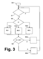
- step St1 is continuously checked whether a load-free rolling condition exists.
- a load-free rolling state is detected when the drive desired torque signal S3 is to be set smaller than a threshold and continues to be required by the brake control device 10 and optionally a retarder control device no use of permanent and wheel brakes. If it is detected in the decision step St1 that there is no such no-load roll state, the process is reset according to branch n before St1.
- step St2 Upon detection of such a load-free roll state, according to the branch y, a differentiation is subsequently made in step St2, which of the calculation methods BV1, BV2, BV3, and in each of the three cases subsequently in the process step St3a, St3b or St3c determines the time duration delta-t (At). Subsequently, according to step St4, it is determined whether delta-t is greater than or equal to the threshold delta-ts ( ⁇ ts), according to which it is worth switching off a secondary unit 12, which may normally be switched on permanently, in order to achieve the energetically favorable phase of the free Roll state (sailing condition) as long as possible to be able to maintain.
- ⁇ ts threshold delta-ts
- step St5a a control signal S5 is output to the clutch 16 for disengaging, and in the case of branch n, according to which delta-t is not greater than / equal to delta-ts, no such control signal S5 is output in step St5b, so that the clutch 16 is further in operative engagement. In both cases, the method is again reset before step St1.
Landscapes
- Engineering & Computer Science (AREA)
- Transportation (AREA)
- Mechanical Engineering (AREA)
- Automation & Control Theory (AREA)
- Chemical & Material Sciences (AREA)
- Combustion & Propulsion (AREA)
- Human Computer Interaction (AREA)
- Control Of Driving Devices And Active Controlling Of Vehicle (AREA)
- Control Of Vehicle Engines Or Engines For Specific Uses (AREA)
- Control Of Transmission Device (AREA)
Abstract
wobei ein lastfreier Rollzustand des Fahrzeugs (1) einstellbar ist und eine voraussichtliche Zeitdauer (Delta-t) des lastfreien Rollzustandes ermittelt wird,
in Abhängigkeit der ermittelten voraussichtlichen Zeitdauer (Delta-t) ein Schaltzustand eines Nebenaggregates (12) eingestellt wird.
Description
- Die Erfindung betrifft ein Verfahren und eine Steuereinrichtung zur Steuerung oder Regelung von Fahrzeugsystemen. Das Verfahren und die Steuereinrichtung können insbesondere als Systemmanagement zur Einstellung und gegebenenfalls Regelung unterschiedlicher Einrichtungen und Komponenten des Fahrzeugs dienen.
- Derartige Fahrzeugsysteme sind unter anderem Fahrdynamikregelungen zur Regelung in Fahrzeuglängsrichtung. Diese können zum einen Geschwindigkeitsregelungen zur Einstellung einer konstanten Fahrgeschwindigkeit sein, die auch als Tempomatfunktion oder CC (Cruise Control)- Regelung bezeichnet wird oder eine Abstandsregelung zur Einstellung eines Wunschabstandes zu einem vorausfahrenden Fahrzeugs sein, die auch als ACC (Adaptive Cruise Control) bezeichnet wird.
- Die
DE 10 2004 017 115 A1 beschreibt derartige Verfahren. Hierbei kann eine Kraftstoff sparende Betriebsart eingestellt werden, indem eine Beschleunigungsphase und eine sich anschließende Ausrollphase des Fahrzeugs eingestellt werden. Eine derartige Ausrollphase wird erreicht, wenn der Motor von seiner Wirkverbindung zu den Rädern unterbrochen wird, d.h. durch Betätigung der Kupplung und/oder Einstellung eines Leerlaufs des Getriebes. In der Ausrollphase kann ergänzend der Verbrennungsmotor ausgeschaltet werden. Bei Erreichen der unteren Geschwindigkeits- Schwelle der Ausrollphase wird vor dem Wechsel der Fahrstufe dann zunächst der Verbrennungsmotor gestartet. Die Entscheidung, ob der Verbrennungsmotor abgeschaltet wird, kann von der Zeit abhängig sein, die das Fahrzeug bis zum Erreichen der unteren Geschwindigkeits- Schwelle schätzungsweise benötigen wird. Bei einer kürzeren benötigten Zeit wird hierbei lediglich ausgekuppelt bzw. das Getriebe in neutrale Position geschaltet. - Die
DE 2008 029 453 A1 beschreibt ein Verfahren zum Einstellen eines so genannten Segelmodus bei einem Kraftfahrzeug, in dem keine Drehmomentübertragung erfolgt, d.h. insbesondere eines ausgekuppelten Zustandes ohne Bremswirkung. Hierbei kann der Segelmodus über einen Tempomat oder eine ACC-Regelung eingestellt werden. Die Einstellung in den Segelmodus kann erfolgen, wenn über eine geeignete Sensorik erkannt wird, dass die momentane Leistungs- bzw. Geschwindigkeitsanforderung auch ohne Motor erfüllbar ist. - Die
WO 2009/060241 A1 beschreibt ein Fahrzeugsystem, bei dem die Position eines Fahrzeugs in Kartendaten angezeigt wird, wobei zur Treibstoffeinsparung ein Freilauf-Modus einstellbar ist und hierfür vorgesehene Streckenbereiche in der Karte angezeigt werden. - Die
EP 1 702 152 B1 beschreibt ein Verfahren und eine Vorrichtung zum Betreiben einer Antriebseinheit eines Fahrzeuges im Schubbetrieb. Hierbei ist vorgesehen, eine Stellgröße der Antriebseinheit einzustellen, wobei diese Stellgröße der Zündwinkel und/oder eine Getriebeübersetzung ist. Hierzu wird eine Fahrsituation ermittelt, bei der die Fahrgeschwindigkeit des eigenen Fahrzeugs oder eines vorausfahrenden Fahrzeugs ausgewertet wird. Hierbei können Schwellwerte des Abstandes zum vorausfahrenden Fahrzeug festgelegt werden. - Die
DE 10 2008 005 328 A1 beschreibt ein Verfahren zum energieeffizienten Betrieb eines Kraftfahrzeuges, bei dem eine Abstandsregelung und eine Fahrzeugumgebungserfassung vorgesehen sind. Hierbei kann insbesondere auch die Geschwindigkeit eines vorausfahrenden Objektes erfasst werden. Weiterhin ist es vorgesehen, in einem Rollzustand des Fahrzeuges den Motor ganz abzuschalten. - Die
DE 10 2007 035 424 A1 beschreibt ein Betriebsverfahren für ein Fahrzeug mit Fahrzeugumfeldsensorik und ACC. Hierbei ist ein Segelzustand des Fahrzeugs mit geöffneter Kupplung automatisch aktivierbar. - Durch derartige Segelfunktionen bzw. Rollzustände des Fahrzeugs, in denen keine Drehmomentübertragung auf die Abtriebswelle (von dem Verbrennungsmotor oder einem Retarder) übertragen wird und weiterhin keine Drehmomentübertragung durch Reibungsbremsen erfolgt, kann eine deutliche Energieeinsparung erreicht werden. Eine derartige Funktion wird im Allgemeinen im Längsregler des ACC oder CC als Regelalgorithmus realisiert. Somit liegt im Längsregler die Information vor, welches Antriebssollmoment (Motor, Dauerbremsen, Radbremsen) anzufordern ist.
- Das Systemmanagement eines Fahrzeugs betrifft weiterhin das Zu- und Abschalten von Nebenaggregaten, d.h. Leistungseinrichtungen bzw. Hilfsmaschinen im Fahrzeug, die nicht unmittelbar die Fortbewegung des Fahrzeugs bewirken. Derartige Nebenaggregate werden vom Motor angetrieben und umfassen insbesondere ein oder mehrere Generatoren, einen Kompressor für ein Druckluftsystem, das in Nutzfahrzeugen für z.B. das Bremssystem und Luftfederungssystem vorgesehen ist, gegebenenfalls einen Kompressor der Klimaanlage und z.B. eine Hydraulikpumpe einer Servolenkung oder eines Hybridantriebes, Kühlmittelpumpe des Motors, Kühlventilator, Kühlmittelpumpe Dauerbremsen oder Nebenabtriebe für Aufbauaggregate. Hierbei ist es bekannt, Nebenaggregate zuzuschalten, wenn ein Bremsvorgang aktiv ist, z.B. bei Betätigen der Radbremsen. Weiterhin können zur Ausnutzung einer Motorbremswirkung Nebenaggregate zugeschaltet werden, um die kinetische Energie des Fahrzeugs zum Antrieb der Nebenaggregate zu nutzen.
- Der Erfindung liegt die Aufgabe zugrunde, ein Verfahren und eine Steuereinrichtung zur Steuerung oder Regelung von Fahrzeugsystemen zu schaffen, die einen geringen Kraftstoffverbrauch bzw. Energieverbrauch ermöglichen.
- Diese Aufgabe wird durch ein Verfahren nach Anspruch 1 und eine Steuereinrichtung nach Anspruch 13 gelöst. Die Unteransprüche beschreiben bevorzugte Weiterbildungen.
- Der Erfindung liegt der Gedanke zugrunde, die Dauer des Segel- oder lastfreien Rollzustandes durch Abschalten von Nebenaggregaten zu maximieren, um den Energieverbrauch zu reduzieren, gleichzeitig aber die Anzahl der unnötigen Zu- und Abschaltvorgänge zu minimieren und zu verhindern. Ein Zuschalten von Nebenaggregaten während Bremsvorgängen kann zwar dahingehend sinnvoll sein, dass während des Bremsvorgangs kein antreibender Motorbetrieb erfolgt und daher keine Energie des Fahrzeugs zum Betrieb des Nebenaggregats genutzt werden kann. Die Zeitdauer des Bremsvorgangs kann jedoch gegebenenfalls kurz sein und von einer Phase mit positivem Motorsollmoment, abgelöst werden. Bei einer Zuschaltung von Nebenaggregaten nur im Bremsbetrieb kann das Nebenaggregat (z.B. Luftkompressor) seine eigentliche Aufgabe nicht oder nur unzureichend erfüllen. Daher ist die zeitliche Ausdehnung des Nebenaggregatbetriebes über Bremssituationen hinaus in der Regel vorteilhaft.
- Erfindungsgemäß wird die voraussichtliche Zeitdauer eines Rollzustandes bzw. Segelzustandes des Fahrzeugs ermittelt; diese Ermittlung kann insbesondere durch Abschätzung erfolgen. Auf Grundlage der so ermittelten voraussichtlichen Zeitdauer des Rollzustandes kann dann entschieden werden, ob ein oder mehrere Nebenaggregate abgeschaltet werden, um hierdurch den Schaltzustand eines Nebenaggregates festzulegen, d.h. ob das Nebenaggregat an den Motor angekoppelt oder ausgekoppelt (bzw. im Leerlaufbetrieb) ist. Hierbei kann insbesondere entschieden werden, ob eine ermittelte voraussichtliche Zeitdauer des Rollzustandes hinreichend groß ist, so dass ein Abschalten des Nebenaggregates als vorteilhaft bzw. lohnenswert bewertet wird, um den energetisch günstigen Zustand zeitlich zu verlängern. Hierzu kann ein Schwellwert angesetzt werden, mit dem die ermittelte voraussichtliche Zeitdauer verglichen wird.
- Somit können Nebenaggregate, die sonst dauerhaft zugeschaltet sind, erfindungsgemäß abgeschaltet werden, um die Rollphase lange aufrecht zu erhalten.
- Gemäß einer bevorzugten Ausführungsform sind verschiedene Berechnungsverfahren für die voraussichtliche Zeitdauer des Rollzustandes vorgesehen. Somit kann für diese Berechnung zunächst eine Differenzierung zwischen verschiedenen Berechnungsverfahren erfolgen, wobei diese Differenzierung insbesondere von dem eigenen Fahrzustand und dem Fahrzustand eines vorderen (vorausfahrenden) Fahrzeugs abhängen kann.
- Hierbei kann insbesondere zwischen drei grundsätzlichen Situationen unterschieden werden. Gemäß einer ersten Situation, für die ein erstes Berechnungsverfahren angesetzt wird, wird ein ACC-geregelte Annäherungsmanöver an das vordere Fahrzeug (Zielfahrzeug) angesetzt und die voraussichtliche Zeitdauer, die für den Rollzustand angesetzt werden kann, als Zeitdauer der Annäherung an das Zielfahrzeug angesetzt. Somit ist für dieses erste Berechnungsverfahren der Ist-Abstand größer als der Soll-Abstand, und die eigene Fahrgeschwindigkeit größer als die Fahrgeschwindigkeit des vorderen Fahrzeugs. Bei diesem ersten Berechnungsverfahren kann weiterhin zwischen zwei Unterverfahren bzw. Situationsprädiktionen unterschieden werden, nämlich dass der Soll-Abstand in der Rollphase exakt mit dv = 0 erreicht wird, d.h. das ausrollende Fahrzeug den Soll-Abstand innerhalb eines Toleranzbereichs bzw. zulässigen Bereichs erreicht. Oder dieser Soll-Abstand wird voraussichtlich unterschritten, so dass das eigene Fahrzeug nach Abbau der Differenzgeschwindigkeit den Soll-Abstand zunächst wieder einzuregeln hat.
- Gemäß dem zweiten Berechnungsverfahren wird angesetzt, dass der derzeitige Ist-Abstand zu gering ist und somit ein ACC-geregeltes Entfernen von dem vorderen Fahrzeug einzustellen ist, z.B. nach einem dichten Einschervorgang.
- Gemäß einem dritten Verfahren wird eine mathematische Beschreibung des zeitlichen Verlaufs des von den Fahrdynamikregelgeräten vorgegebenen Antriebssollmomentes betrachtet und hieraus die zeitliche Dauer projiziert, bis das Fahrzeug den Rollzustand wieder verlassen wird. Das dritte Bewertungsverfahren führt somit vorzugsweise eine zeitliche Extrapolation aufgrund der vorherigen Zustände ohne eine Betrachtung der Bewegungsgrößen des eigenen oder vorderen Fahrzeugs durch. Das dritte Bewertungsverfahren ist somit insbesondere auch für Tempomatfunktionen (CC) relevant, weiterhin für Abstandsregelverfahren (ACC).
- Grundsätzlich sind auch Kombinationen dieser drei Bewertungsverfahren möglich, z.B. die Verwendung des dritten Bewertungsverfahrens mit Einschränkungen bzw. Ausschlusskriterien, dass z.B. ein Minimalabstand zum vorderen Fahrzeug nicht unterschritten wird.
- Erfindungsgemäß werden einige Vorteile erreicht. Es kann aufgrund der im Fahrzeug vorhandenen Daten, insbesondere Daten aus einem CC- oder ACC-System, eine Zeitdauer eines Rollzustandes abgeschätzt werden, um auf Grundlage dieser Abschätzung bzw. Bewertung zu entscheiden, Nebenaggregate zeitweise abzuschalten bzw. ein Zuschalten zu unterdrücken. Dies ist insbesondere für Nebenaggregate sinnvoll, die nur zeitweise anzutreiben sind, z.B. einen Generator.
- Somit kann der Energieverbrauch verringert werden, ein komfortables Fahrverhalten ohne unnötige Zu- und Abschaltungen bzw. Ein- und Auskupplungen von Nebenaggregaten erreicht werden und auch der Verschleiß der Nebenaggregate bzw. von deren Kupplungen gering gehalten werden.
- In das erfindungsgemäße Verfahren können ergänzend z.B. auch Daten der Fahrzeugumgebung, z.B. Kartendaten oder aus Kartendaten oder vorherigen Fahrten gespeicherte Verbrauchswerte von z.B. Daten über Steigungen und Gefälle der Fahrstrecke mit einbezogen werden, weiterhin auch zusätzliche Messdaten über die Fahrzeugumgebung.
- Die erfindungsgemäße Steuereinrichtung wird somit nach einem erfindungsgemäßen Verfahren gesteuert oder geregelt; hierzu wird sie insbesondere in Abhängigkeit der ermittelten voraussichtlichen Zeitdauer einen Schaltzustand eines Nebenaggregates einstellen.
- Die Erfindung wird im Folgenden anhand der beiliegenden Zeichnungen an einigen Ausführungsformen erläutert. Es zeigen:
- Fig. 1
- eine Straßenszene bzw. Fahrsituation auf einer Straße;
- Fig. 2
- das Fahrzeug 1 aus
Fig. 1 mit seinen wesentlichen Funktionseinrichtungen als Blockschaltbild; - Fig. 3
- ein Flussdiagramm eines erfindungsgemäßen Verfahrens.
- Ein erfindungsgemäßes Fahrzeug 1 fährt hinter einem vorderen Fahrzeug 2 auf einer Fahrbahn 3. Das Fahrzeug 1 ist mit einem ACC- Regelsystem (Adaptive Cruise Control) zur Abstandsregelung zu dem vorderen Fahrzeug 2 ausgestattet. Das Fahrzeug 1 weist einen Verbrennungsmotor 4 (oder auch einen Hybridmotor 4) mit einem Motorsteuergerät 5 sowie eine Steuereinrichtung 6 zur Längsregelung und Abstandshaltefunktion auf, wobei die Steuereinrichtung 6 von einem Geschwindigkeitssensor 7 ein Geschwindigkeitssignal S1 aufnimmt, das die eigene Geschwindigkeit v1 des Fahrzeugs 1 wiedergibt, und weiterhin ein Abstandsmesssignal S2 eines Abstandssensors 8 aufnimmt, der direkt den Ist-Abstand dxist des eigenen Fahrzeugs 1 zu dem vorderen Fahrzeug 2 misst, z.B. mittels Radar, Ultraschall, Laser oder gegebenenfalls Stereo-Kamera.
- Das Geschwindigkeitssignal S1 kann in an sich bekannter Weise aus der Drehzahl der Abtriebswelle und/oder aus ABS-Drehzahlsensoren bzw. einer aus den ABS-Drehzahlen ermittelten Referenzgeschwindigkeit abgeleitet werden. Ergänzend kann das Fahrzeug 1 auch einen Längsbeschleunigungssensor zur Ermittlung der Längsbeschleunigung a1 aufweisen. Die Längsbeschleunigung a1 kann jedoch auch von der Steuereinrichtung 6 durch die zeitliche Ableitung der Geschwindigkeit v1 ermittelt werden. Die Steuereinrichtung 6 berechnet ein Antriebssollmoment, das positiv oder negativ sein kann, um daraus einzelne Sollmomente für Motor und Dauerbremsen zu bestimmen. Die Steuereinrichtung 6 der Abstandshalteregelung nimmt Daten von dem Motorsteuergerät 5 auf und gibt entsprechend Daten an dieses aus, insbesondere ein Antriebssollmoment- Signal S3 mit dem angeforderten, indizierten Antriebsstrangmoment, das somit das Motorsollmoment mit umfasst. Weiterhin gibt die Steuereinrichtung 6 des ACC Sollmomente an die Dauerbremsen aus, sowie ein Steuersignal S4 an eine Bremssteuereinrichtung 10 eines hier nicht detaillierter gezeigten Bremssystems aus, und ein Steuersignal S6 an eine Getriebesteuerung 18 (automatischer Getriebesteller) einer schematisiert gezeichneten, dem Motor 4 nachgeschalteten Kupplungs- Getriebeeinheit 20, z. B. zum Auskuppeln bzw. Einstellung eines Leerlaufs für einen Rollzustand.
- Über die Einstellung der Motorfunktion, Betätigung der Dauerbremsen, Getriebestellung und Bremsbetätigung führt die Steuereinrichtung 6 die Abstandsregelung durch, bei der z.B. in Abhängigkeit der eigenen Fahrgeschwindigkeit v1, der Längsbeschleunigung a1 sowie der Geschwindigkeit v2 des vorderen Fahrzeugs 2 ein Soll-Abstand dxsoll ermittelt und der gemessene Istabstand dxist auf den Soll-Abstand dxsoll eingestellt wird.
- Das Fahrzeug 1 weist weiterhin ein oder mehrere Nebenaggregate 12 auf, z.B. einen Generator ( bei einem Fahrzeug mit Verbrennungsmotor oder auch für Hybridantriebe), eine Kühlmittelpumpe des Motors, eine Kühlmittelpumpe einer Dauerbremse, eine Klimaanlage bzw. einen Klimakompressor, oder ein Kompressor oder ein Nebenabtrieb für Aufbauaggregate des als Nutzfahrzeug ausgebildeten Fahrzeugs 1, und/oder eine Pumpe für eine Servolenkung. Das Nebenaggregat 12 ist über eine Wirkverbindung 4a mit einer Kupplung 16 an den Verbrennungsmotor 4 direkt oder indirekt zuschaltbar. Die Zu- und Abschaltung kann bei z.B. einem Kompressor als Nebenaggregat 12 statt über die Kupplung 16 auch durch elektrisches Abschalten des Nebenaggregates 12 , Umschalten des Nebenaggregates 12 zwischen einem Energiesparbetrieb bzw. Leerlauf und einem Lastlauf erfolgen. Nachfolgend wird beispielhaft weiter die Ansteuerung der Kupplung 16 beschrieben.
- Die Steuereinrichtung 6 des ACC kann direkt oder indirekt durch Steuersignale S5 die Kupplung 16 schalten bzw. die Wirkverbindung 4a öffnen und schließen. Hierbei können die Schaltsignale auch nicht direkt von der Steuereinrichtung 6, sondern einer mit der Steuereinrichtung 6 verbundenen weiteren Steuereinrichtung der Kupplung 16 ausgegeben werden, so dass die Steuereinrichtung 6 die Steuersignale S5 an diese Steuereinrichtung der Kupplung 16 ausgibt.
- Sämtliche Signale S1 bis S6 können insbesondere über ein oder mehrere fahrzeuginterne CAN-Busse übertragen werden.
- Die Steuereinrichtung 6 des ACC ermittelt aus dem berechneten Antriebssollmoment- Signal S3 bzw. Motorsollmoment-Signal, ob derzeit ein lastfreier Betrieb des Verbrennungsmotors 4 bzw. Leerlauf des Verbrennungsmotors 4 vorgesehen ist, bei dem somit die Kupplungs- Getriebeeinheit 20 in Leerlaufstellung bzw. offen ist. Derartige Informationen können statt aus dem Antriebssollmoment gegebenenfalls auch von der Getriebesteuerung 18 an die Steuereinrichtung 6 ausgegeben werden.
- Weiterhin ermittelt die Steuereinrichtung 6 des ACC, über welchen Zeitraum Delta-t dieser lastfreie Betrieb des Verbrennungsmotors 4 voraussichtlich eingestellt sein soll bzw. werden wird. Diese Zeitdauer Delta-t stellt somit einen Schätzwert dar, da aufgrund z.B. nicht vorhersehbarer Ereignisse wie einer Bremsbetätigung oder Beschleunigung des vorderen Fahrzeugs 2 oder auch durch den Fahrerwunsch aufgrund Betätigung des Gaspedals oder des Bremspedals der später tatsächlich erreichte Zeitraum von dem Wert Delta-t im Allgemeinen abweichen kann.
- Zur Abschätzung des Zeitraums Delta-t werden gemäß einer bevorzugten Ausführungsform die derzeitige Fahrsituation des Fahrzeugs 1 hinter dem Fahrzeug 2 grob klassifiziert und in Abhängigkeit davon verschiedene Berechnungsverfahren BV1, BV2, BV3 eingesetzt:
- Berechnungsverfahren BV1 nutzt die mathematische Beschreibung eines ACC-geregelten Annäherungsmanövers des Fahrzeugs 1 an das vordere Fahrzeug 2. Somit ist dxist > dxsoll und v1 > v2, d.h. im derzeitigen lastfreien Rollzustand nähert sich das eigene Fahrzeug 1 dem vorderen Fahrzeug 2 an; die Differenzgeschwindigkeit dvist = v2ist - v1ist ist somit kleiner Null.
- Als Zeitdauer Delta-t des (prädizierten) lastfreien Rollzustandes wird die Zeitdauer abgeschätzt, in der sich der Soll-Abstand dxsoll zum vorderen Fahrzeug 2 eingestellt haben wird. Hierbei wird vorteilhafterweise im Detail zwischen zwei Situationsprädiktionen unterschieden:
- BV1 a: Der Soll-Abstand dxsoll wird (gemäß derzeitigen Abschätzungen der Fahrzustandsgrößen des eigenen Fahrzeugs 1 und des vorderen Fahrzeugs 2, d.h. vermutlich mit dv = 0) erreicht. Im Allgemeinen wird ein Zielabstand bzw. Soll-Abstand dxsoll angegeben, z.B. insbesondere abhängig von v1, und für dxsoll ein Ziel- Abstandsbereich definiert durch einen unteren Grenzwert dxsu sowie einen oberen Grenzwert dxso , z.B. mit +/- 2m um dxsoll. herum
- BV1a wird somit erreicht, wenn aufgrund der derzeitigen Fahrzeugbewegungen des eigenen Fahrzeugs 1 und des vorderen Fahrzeugs 2 bei Ausnutzung des Rollzustandes dieser Ziel- Abstandsbereich (dxsu, dxso) mit dv = 0 erreicht wird. Somit kann die Zeitdauer Delta-t berechnet werden über die Gleichung Delta-t = dvist/daist mit dvist als Differenzgeschwindigkeit der Istgeschwindigkeiten v1 und v2 der Fahrzeuge 1 und 2 und entsprechend daist der Differenz-Beschleunigung der Istbeschleunigungen a1 und a2 der Fahrzeuge 1 und 2.
- BV1b: gemäß der zweiten Situationsprädiktion des ersten Berechnungsverfahrens BV1 wird der Soll-Abstand dxsoll gemäß den derzeitigen Fahrzustandsdaten der Fahrzeuge 1 und 2 vermutlich unterschritten, so dass das eigene Fahrzeug 1 nach dem Abbau der Differenzgeschwindigkeit dv den Soll-Abstand dxsoll zum vorderen Fahrzeug 1 erst wieder neu einzuregeln hat; hierbei kann die Zeitdauer Delta-t berechnet werden über Delta-t = dvist/daist + (dxsoll - dxist)/dvsoll .
- Bei dem Berechnungsverfahren BV1 wird somit aufgrund der höheren eigenen ersten Geschwindigkeit v1 bzw. negativer Differenzgeschwindigkeit dvist= v2-v1 der Soll-Abstand dxsoll erreicht, entweder gemäß BV1 a direkt passend oder gemäß BV1 b mit verbleibender Restgeschwindigkeit, so dass weiter verzögert und - mit dem dazu erforderlichen Zuschalten des Motors wieder neu einzuregeln ist.
- BV2: Es wird ein Entfernen des eigenen Fahrzeugs 1 vom vorderen Fahrzeuge 2 während des Rollzustands angesetzt, z.B. nach einem dichten Einschervorgang, bei dem dxist < dxsoll ist. Gemäß dem zweiten Berechnungsverfahren BV2 wird die mathematische Beschreibung eines ACC-geregelten Entfernens des eigenen Fahrzeugs 1 von dem vorderen Fahrzeug 2 beschrieben, und als Zeitdauer Delta-t die zeitliche Dauer bestimmt, in der sich der Soll-Abstand dxsoll zum vorderen Fahrzeug 1 eingestellt haben wird. Hierbei kann die Zeitdauer Delta-t berechnet werden über Delta-t = (dxsoll - dxist)/ dvsoll.
- BV3: Bei dem dritten Berechnungsverfahren wird die mathematische Beschreibung des Verlaufs des von dem ACC oder auch einer Tempomatfunktion (CC) vorgegebenen Antriebssollmoments -Signals S3 genutzt, und mit Hilfe des aus der Signalhistorie, d.h. dem zeitlichen Verhalten S3 = S3 (t), die zukünftige Sollmoment-Entwicklung abgeschätzt, d.h. zu extrapolieren bzw. prädizieren. Vorteilhafterweise wird hierzu aus der Signalhistorie ein zeitlicher Gradient, d.h. die erste Ableitung nach der Zeit t ermittelt. Gemäß diesem dritten Berechnungsverfahren wird somit die zeitliche Dauer Delta-t abgeschätzt.
- Bei BV3 kann das Antriebssollmoment-Signal S3 linear extrapoliert werden, d.h. dessen derzeitiger zeitlicher Gradient als konstant angesehen und eine lineare Extrapolation in der Zeit t vorgenommen werden, so dass gemäß BV3 eine kontinuierliche, lineare Änderung (Erhöhung oder Absenkung) des Antriebssollmoment-Signals S3 angenommen wird. Ergänzend kann auch die zweite zeitliche Ableitung herangezogen werden, d.h. eine Extrapolation in erster und zweiter zeitlicher Ableitung vorgenommen werden.
- Zur Differenzierung zwischen den drei Berechnungsverfahren BV1, BV2 und BV3, insbesondere auch zur weiteren Unterdifferenzierung von BV1 in BV1a und BV1b, sind vorteilhafterweise Gültigkeitsbereiche definiert, die abhängen von den Bewegungsgrößen des eigenen Fahrzeugs 1 und des vorderen Fahrzeugs 2, d.h. von dxist, v1ist, v2ist, a1ist, a2ist. Hierbei kann z.B. die derzeitige Istbeschleunigung a1ist und a2ist in der Zukunft als konstant bleibend angesetzt werden, d.h. eine Bewegungsgleichung in zweiter Ordnung der Zeit angesetzt werden. Diese Gültigkeitsbereiche legen für den gesamten relevanten Betriebsbereich fest, welches der Berechnungsverfahren BV1, BV2, BV3 jeweils Anwendung findet. Erfindungsgemäß kann zwischen diesen Berechnungsverfahren bzw. Methoden bedarfsgerecht umgeschaltet werden.
- Nachdem Delta-t ermittelt ist, kann es mit einem Schwellwert Delta-ts verglichen werden, der festlegt, ob es sich lohnt, das Nebenaggregat 12 abzuschalten, d.h. es wird Delta-t>Delta-ts oder Delta-t ≥ Delta-ts überprüft.
- Das erfindungsgemäße Verfahren wird somit durch
Fig. 3 beschrieben, wonach es in einem Schritt St0 gestartet wird. Im Schritt St1 wird fortwährend überprüft, ob ein lastfreier Rollzustand vorliegt. Ein derartiger lastfreier Rollzustand wird erkannt, wenn das Antriebssollmoment -Signal S3 kleiner als eine Schwelle anzusetzen ist und weiterhin von der Bremssteuereinrichtung 10 und gegebenenfalls einer Retardersteuereinrichtung keine Nutzung von Dauer- und Radbremsen gefordert wird. Falls in dem Entscheidungsschritt St1 erkannt wird, dass kein derartiger lastfreier Rollzustand vorliegt, wird das Verfahren gemäß Verzweigung n vor St1 zurückgesetzt. Bei Erkennen eines derartigen lastfreien Rollzustandes wird gemäß der Verzweigung y nachfolgend in Schritt St2 differenziert, welche der Berechnungsverfahren BV1, BV2, BV3 anzusetzen ist, und in jedem der drei Fälle nachfolgend in dem Prozessschritt St3a, St3b oder St3c die Zeitdauer Delta-t (Δt) ermittelt. Nachfolgend wird gemäß Schritt St4 ermittelt, ob Delta-t größer/gleich dem Schwellwert Delta-ts (Δts) ist, gemäß dem es sich lohnt, ein Nebenaggregat 12, das normalerweise dauerhaft zugeschaltet sein kann, abzuschalten, um die energetisch günstige Phase des freien Rollzustandes (Segelzustandes) so lange wie möglich aufrecht erhalten zu können. - Nachfolgend wird dann gemäß Verzweigung y in Schritt St5a ein Steuersignal S5 an die Kupplung 16 zum Auskuppeln ausgegeben, und im Fall der Verzweigung n, gemäß dem Delta-t nicht größer/gleich Delta-ts ist, in Schritt St5b kein derartiges Steuersignal S5 ausgegeben, so dass die Kupplung 16 weiter in Wirkeingriff ist. In beiden Fällen wird das Verfahren wiederum vor den Schritt St1 zurückgesetzt.
-
- 1
- Fahrzeug
- 2
- vorderes Fahrzeug
- 3
- Fahrbahn
- 4
- Verbrennungsmotor
- 4a
- Wirkverbindung
- 5
- Motorsteuergerät
- 6
- Steuereinrichtung
- 7
- Geschwindigkeitssensor
- 8
- Abstandssensor
- 10
- Bremssteuereinrichtung
- 12
- Nebenaggregat
- 16
- Kupplung
- 18
- Getriebesteuerung
- 20
- Kupplungs- Getriebeeinheit
- S1
- Geschwindigkeitssignal
- S2
- Abstandsmesssignal
- S3
- Antriebssollmoment- Signal
- S4
- Steuersignal an Bremssteuereinrichtung 10
- S5
- Steuersignal an Kupplung 16
- S6
- Steuersignal an Getriebesteuerung 18
- v1
- Geschwindigkeit des Fahrzeugs 1
- vist
- Ist-Geschwindigkeit/ Ist-Wert von v1
- vsoll
- Soll-Geschwindigkeit/ Soll-Wert von v1
- v2
- Geschwindigkeit des vorderen Fahrzeugs 2
- a1
- Längsbeschleunigung des Fahrzeugs 1
- a2
- Längsbeschleunigung des vorderen Fahrzeugs 2
- dxist
- Ist-Abstand
- dxsoll
- Soll-Abstand
- dxsu , dxso
- Sollabstand-Bereiches
- dv
- Differenzgeschwindigkeit
- dvist
- Differenzgeschwindigkeit, Ist-Wert von dv
- daist
- Differenzbeschleunigung
- Delta-t
- Zeitdauer
- Delta-ts
- Schwellwert
- BV1, BV2, BV3
- Berechnungsverfahren
- BV1a, BV1 b
- Berechnungsverfahren
Claims (15)
- Verfahren zur Steuerung oder Regelung von Fahrzeugsystemen (1), bei dem eine Regelung von Fahrzustandsgrößen (v1, a1) eines Fahrzeugs (1) durchgeführt wird,
wobei ein lastfreier Rollzustand des Fahrzeugs (1) einstellbar ist und eine voraussichtliche Zeitdauer (Delta-t) des lastfreien Rollzustandes ermittelt wird,
dadurch gekennzeichnet, dass
in Abhängigkeit der ermittelten voraussichtlichen Zeitdauer (Delta-t) ein Schaltzustand eines Nebenaggregates (12) eingestellt wird. - Verfahren nach Anspruch 1, dadurch gekennzeichnet, dass die ermittelte voraussichtliche Zeitdauer (Delta-t) des lastfreien Rollzustandes mit einem vorgegebenen Schwellwert (Delta-ts) verglichen wird und in Abhängigkeit des Vergleichs entschieden wird, ob der Schaltzustand des Nebenaggregats (12) geändert wird oder nicht.
- Verfahren nach Anspruch 1 oder 2, dadurch gekennzeichnet, dass als Regelung durchgeführt wird- eine Abstandsregelung zu einem vorausfahrenden Fahrzeug (2) unter Messung eines Abstands (dxist) zu dem vorderen Fahrzeug (2) und mindestens einer eigenen Fahrzustandsgröße (v1, a1) des Fahrzeugs (1), und/oder- eine Tempomat-Regelung zur Einstellung einer festen Geschwindigkeit (v1) des Fahrzeugs (1).
- Verfahren nach einem der vorherigen Ansprüche, dadurch gekennzeichnet, dass bei Erkennen, dass die voraussichtliche Zeitdauer (Delta-t) den Schwellwert (Delta-ts) erreicht oder überschreitet, das Nebenaggregat (12) von seiner Wirkverbindung (4a) zu einem Antriebsmotor (4) des Fahrzeugs (1) abgekoppelt wird und/oder eine Einkupplung unterlassen wird.
- Verfahren nach einem der vorherigen Ansprüche, dadurch gekennzeichnet, dass das Nebenaggregat (12) eines oder mehrere aus folgender Gruppe ist/sind:Generator für ein Fahrzeug mit Verbrennungsmotor oder Hybridantrieb, Kompressor zur Druckluftförderung, Kompressor einer Klimaanlage, Pumpe einer Servolenkung, Kühlmittelpumpe für den Motor, Kühlmittelpumpe für die Dauerbremse, Nebenabtrieb für Aufbauaggregate.
- Verfahren nach einem der vorherigen Ansprüche, dadurch gekennzeichnet, dass die voraussichtliche Zeitdauer (Delta-t) des lastfreien Rollzustandes mittels der Verwendung von mindestens zwei der folgenden Größen ermittelt wird, welche ausgewählt sind aus der Gruppe, die folgende Größen aufweist:- Geschwindigkeit (v1, vist, vsoll) des Fahrzeugs (1),- Beschleunigung (a1) des Fahrzeugs (1),- dem aktuellen Abstand (dxist) des Fahrzeugs (1) zu dem vorderen Fahrzeug (2),- dem Soll-Abstand (dxsoll) des Fahrzeugs (1) zu dem vorderen Fahrzeug (2),- zweite Geschwindigkeit (v2) des vorderen Fahrzeugs (2),- zweite Beschleunigung (a2) des vorderen Fahrzeugs (2),- aktuelle Differenzgeschwindigkeit (dvist) zwischen dem vorderen Fahrzeug (2) und dem Fahrzeug (1)- aktuelle Differenzbeschleunigung (daist),
insbesondere durch eine Bewegungsgleichung erster oder zweiter Ordnung der Zeit. - Verfahren nach einem der vorhergehenden Ansprüche, dadurch gekennzeichnet, dass in Abhängigkeit der Fahrzustandsgrößen des Fahrzeugs (1) und des vorderen Fahrzeugs (2) zwischen mehreren alternativen Berechnungsverfahren (BV1a, BV1b, BV2, BV3) ausgewählt wird.
- Verfahren nach Anspruch 7, dadurch gekennzeichnet, dass ein erstes Berechnungsverfahren (BV1a, BV1 b) vorgesehen ist, das die mathematische Beschreibung eines ACC-geregelten Annäherungsvorgangs des Fahrzeugs (1) an das vordere Fahrzeug (2) verwendet und die voraussichtliche Zeitdauer (Delta-t) als Zeitdauer des Erreichens eines Soll-Abstandes (dxsoll) oder Sollabstand-Bereiches (dxsu , dxso) zum vorderen Fahrzeug (2) ermittelt.
- Verfahren nach Anspruch 8, dadurch gekennzeichnet, dass in dem ersten Berechnungsverfahren (BV1) zwischen zwei Unterverfahren (BV1a, BV1 b) unterschieden wird, wobei das erste Unterverfahren (BV1 a) angesetzt wird, wenn durch den Rollzustand des Fahrzeugs (1) der Soll-Abstand (dxsoll) innerhalb des Sollabstand-Bereiches (dxsu , dxso ) erreichbar ist mit dann dv = 0, wobei die voraussichtliche Zeitdauer (Delta-t) ermittelbar ist über eine Verhältnisbildung der derzeitigen Differenzgeschwindigkeit (dvist) zwischen dem vorderen Fahrzeug (2) und dem Fahrzeug (1) und der derzeitigen Differenzbeschleunigung (daist) zwischen dem vorderen Fahrzeug (2) und dem Fahrzeug (1), insbesondere durch Delta-t = dvist/daist mit:Delta-t voraussichtlicher Zeitdauer, dvist derzeitige Differenzgeschwindigkeit zwischen dem vorderen Fahrzeug (2) und dem Fahrzeug (1),daist derzeitige Differenzbeschleunigung zwischen dem vorderen Fahrzeug (2) und dem Fahrzeug (1).
- Verfahren nach Anspruch 8 oder 9, dadurch gekennzeichnet, dass das zweite Unterverfahren (BV1 b) verwendet wird, wenn ermittelt wird, dass das Fahrzeug (1) durch den Rollzustand den Soll-Abstand (dxsoll) und/oder Sollabstand-Bereich (dxsu , dxso ) voraussichtlich unterschreitet, wobei die voraussichtliche Zeitdauer (Delta-t) ermittelbar ist über
Delta-t = dvist/daist+( (dxsoll-dxist) / dvsollentfernen ), mit Delta-t voraussichtlicher Zeitdauer, dvist derzeitige Differenzgeschwindigkeit zwischen dem vorderen Fahrzeug (2) und dem Fahrzeug (1), daist derzeitige Differenzbeschleunigung zwischen dem vorderen Fahrzeug (2) und dem Fahrzeug (1), dxist derzeitiger Abstand des Fahrzeugs (1) zu dem vorderen Fahrzeug (2) und dxsoll Soll-Abstand des Fahrzeugs (1) zu dem vorderen Fahrzeug, dvsollentfernen Solldifferenzgeschwindigkeit zum Vergrößern des Abstandes zum vorderen Fahrzeug nach dem Annähern. - Verfahren nach einem der Ansprüche 7 bis 10, dadurch gekennzeichnet, dass ein zweites Berechnungsverfahren (BV2) zur Ermittlung der voraussichtlichen Zeitdauer (Delta-t) verwendet wird, wenn ermittelt wird, dass der aktuelle Abstand (dxist) zu dem vorderen Fahrzeug (2) unterhalb eines Soll-Abstandes (dxsoll) oder Sollabstand-Bereiches (dxsu , dxso ) liegt, wobei eine mathematische Beschreibung eines ACC-geregelten Entfernens von dem vorderen Fahrzeug (2) verwendet wird und die voraussichtliche Zeitdauer (Delta-t) als Zeitdauer des Entfernens des Fahrzeugs (1) von dem vorderen Fahrzeug (2) ermittelt wird, wobei vorzugsweise gilt:Delta-t=(dxsoll-dxist)/dvsollentfernen mit:Delta-t voraussichtlicher Zeitdauer, dvsollentfernen Soll-Differenzgeschwindigkeit zwischen dem vorderen Fahrzeug (2) und dem Fahrzeug (1),dxist derzeitiger Abstand des Fahrzeugs (1) zu dem vorderen Fahrzeug (2) unddxsoll Soll-Abstand des Fahrzeugs (1) zu dem vorderen Fahrzeug (2).
- Verfahren nach einem der Ansprüche 7 bis 11, dadurch gekennzeichnet, dass ein drittes Bewertungsverfahren (BV3) verwendet wird, bei dem das zeitliche Verhalten eines Antriebssollmoment-Signals (S3) zur Einstellung des Sollmomentes der Antriebsstrangparameter (2) bewertet wird und die voraussichtliche Zeitdauer (Delta-t) aus der Bewertung des zeitlichen Verhaltens des Antriebssollmoment-Signals (S3) abgeschätzt wird, vorzugsweise durch Bewertung des zeitlichen Gradienten des Antriebssollmoment-Signals (S3).
- Verfahren nach Anspruch 12, dadurch gekennzeichnet, dass bei dem dritten Bewertungsverfahren (BV3) eine Projektion oder zeitliche Extrapolation durchgeführt wird mit konstantem zeitlichen Gradient des Antriebssollmoment-Signals (S3).
- Steuereinrichtung (6) zur Steuerung oder Regelung von Fahrzeugsystemen, vorzugsweise eines Abstandsregelungsverfahrens oder Geschwindigkeitsregelungsverfahrens, insbesondere zur Durchführung eines Verfahrens nach einem der vorherigen Ansprüche wobei die Steuereinrichtung (6) aufweist:mindestens eine Schnittstelle zur Aufnahme von Signalen (S1) über Fahrdynamikdaten des Fahrzeugs (1) und eines Abstandssignals (S2) zu einem vorderen Fahrzeug (2) und zur Ausgabe von Steuersignalen (S3, S4, S5, S6) zur Veränderung des Fahrzustandes des Fahrzeugs (1), insbesondere durch Bremseingriff oder Motoreingriff oder Getriebeeingriff, undeine Steuereinrichtung (6) zur Regelung von Fahrzustandsgrößen (v1, a1) des Fahrzeugs (1),wobei ein lastfreier Rollzustand des Fahrzeugs (1) einstellbar ist und eine voraussichtliche Zeitdauer (Delta-t) des lastfreien Rollzustandes ermittelt wird,dadurch gekennzeichnet, dass
die Steuereinrichtung (6) in Abhängigkeit der ermittelten voraussichtlichen Zeitdauer (Delta-t) einen Schaltzustand eines Nebenaggregates (12) einstellt. - Fahrzeug (1) mit einer Steuereinrichtung (6) nach Anspruch 14.
Applications Claiming Priority (1)
| Application Number | Priority Date | Filing Date | Title |
|---|---|---|---|
| DE102011106342A DE102011106342A1 (de) | 2011-07-01 | 2011-07-01 | Verfahren und Steuereinrichtung zur Steuerung oder Regelung von Fahrzeugsystemen |
Publications (3)
| Publication Number | Publication Date |
|---|---|
| EP2540589A2 true EP2540589A2 (de) | 2013-01-02 |
| EP2540589A3 EP2540589A3 (de) | 2015-12-23 |
| EP2540589B1 EP2540589B1 (de) | 2017-06-28 |
Family
ID=46027516
Family Applications (1)
| Application Number | Title | Priority Date | Filing Date |
|---|---|---|---|
| EP12002413.8A Active EP2540589B1 (de) | 2011-07-01 | 2012-04-03 | Verfahren und Steuereinrichtung zur Steuerung oder Regelung von Fahrzeugsystemen |
Country Status (3)
| Country | Link |
|---|---|
| EP (1) | EP2540589B1 (de) |
| DE (1) | DE102011106342A1 (de) |
| ES (1) | ES2637203T3 (de) |
Cited By (9)
| Publication number | Priority date | Publication date | Assignee | Title |
|---|---|---|---|---|
| WO2014098653A1 (en) * | 2012-12-19 | 2014-06-26 | Volvo Truck Corporation | Method and arrangement for determining the speed behaviour of a leading vehicle |
| FR3017355A1 (fr) * | 2014-02-10 | 2015-08-14 | Peugeot Citroen Automobiles Sa | Procede et dispositif d'aide a la conduite d'un vehicule suivant un autre vehicule, en fonction de la pente |
| WO2016007073A1 (en) * | 2014-07-07 | 2016-01-14 | Scania Cv Ab | Control of an internal combustion engine in a vehicle |
| FR3046979A1 (fr) * | 2016-01-27 | 2017-07-28 | Peugeot Citroen Automobiles Sa | Dispositif de regulation adaptative de la vitesse d'un vehicule, a moyens de decision |
| WO2017140968A1 (fr) * | 2016-02-18 | 2017-08-24 | Peugeot Citroen Automobiles Sa | Dispositif de détermination de paramètres pour un système de régulation adaptative de la vitesse d'un véhicule |
| US10495013B2 (en) | 2014-07-07 | 2019-12-03 | Scania Cv Ab | Control of preparatory measures in a vehicle |
| US10507840B2 (en) | 2014-07-07 | 2019-12-17 | Scania Cv Ab | Control of an combustion engine in a vehicle |
| DE102019200773A1 (de) * | 2019-01-23 | 2020-07-23 | Thyssenkrupp Ag | Tagebau-Anordnung und Verfahren zum Betreiben einer Tagebau-Anordnung |
| CN112758093A (zh) * | 2021-01-25 | 2021-05-07 | 北京罗克维尔斯科技有限公司 | Acc车速控制方法、装置、acc控制器、存储介质及车辆 |
Families Citing this family (3)
| Publication number | Priority date | Publication date | Assignee | Title |
|---|---|---|---|---|
| DE102013207129A1 (de) * | 2013-04-19 | 2014-10-23 | Bayerische Motoren Werke Aktiengesellschaft | Verfahren zum Aktivieren oder Deaktivieren eines Segelmodus in einem Kraftfahrzeug |
| FR3033540B1 (fr) * | 2015-03-10 | 2017-03-24 | Peugeot Citroen Automobiles Sa | Procede et dispositif de controle de l’ouverture / fermeture de la chaine de transmission d’un vehicule suivant un autre vehicule |
| DE102018220160A1 (de) | 2018-11-23 | 2020-05-28 | Zf Friedrichshafen Ag | Verfahren zum Steuern eines Roll- oder Segelzustands |
Citations (6)
| Publication number | Priority date | Publication date | Assignee | Title |
|---|---|---|---|---|
| DE102004017115A1 (de) | 2004-04-07 | 2005-10-27 | Zf Friedrichshafen Ag | Verfahren zur Geschwindigkeitsregelung für ein Fahrzeug mit automatischem oder automatisiertem Getriebe |
| EP1702152B1 (de) | 2003-12-20 | 2007-05-09 | Robert Bosch Gmbh | Verfahren und vorrichtung zum betreiben einer antriebseinheit eines fahrzeugs im schubbetrieb |
| DE102008005328A1 (de) | 2008-01-21 | 2008-07-31 | Daimler Ag | Verfahren zum energieeffizienten Betrieb eines Kraftfahrzeuges |
| DE102007035424A1 (de) | 2007-07-28 | 2009-01-29 | Dr. Ing. H.C. F. Porsche Aktiengesellschaft | Fahrzeug, Betriebsverfahren und Bedienschnittstelle |
| WO2009060241A1 (en) | 2007-11-08 | 2009-05-14 | Jason Robert Bunn | Vehicle system |
| DE102008029453A1 (de) | 2008-06-21 | 2009-12-24 | Bayerische Motoren Werke Aktiengesellschaft | Verfahren zum Einstellen eines sog." Segelmodus" bei einem Kraftfahrzeug |
Family Cites Families (5)
| Publication number | Priority date | Publication date | Assignee | Title |
|---|---|---|---|---|
| SE508156C2 (sv) * | 1996-10-18 | 1998-09-07 | Volvo Lastvagnar Ab | System och metod för reglering av inkopplingen av hjälputrustning driven av en motor |
| FR2811440B1 (fr) * | 2000-07-06 | 2003-07-25 | Renault | Procede de regulation adaptative de la distance entre deux vehicules mobiles |
| DE10320009A1 (de) * | 2003-05-06 | 2004-12-02 | Robert Bosch Gmbh | Verfahren zum Betreiben eines Fahrzeugs |
| DE102006034411A1 (de) * | 2006-07-25 | 2008-01-31 | Robert Bosch Gmbh | Vorrichtung zur Geschwindigkeits- und Anhalteregelung in Kraftfahrzeugen |
| DE102007032968A1 (de) * | 2007-07-16 | 2009-01-29 | Knorr-Bremse Systeme für Nutzfahrzeuge GmbH | Verfahren und Vorrichtung zum Ermitteln von Schubbetrieben eines Fahrzeugs |
-
2011
- 2011-07-01 DE DE102011106342A patent/DE102011106342A1/de not_active Withdrawn
-
2012
- 2012-04-03 ES ES12002413.8T patent/ES2637203T3/es active Active
- 2012-04-03 EP EP12002413.8A patent/EP2540589B1/de active Active
Patent Citations (6)
| Publication number | Priority date | Publication date | Assignee | Title |
|---|---|---|---|---|
| EP1702152B1 (de) | 2003-12-20 | 2007-05-09 | Robert Bosch Gmbh | Verfahren und vorrichtung zum betreiben einer antriebseinheit eines fahrzeugs im schubbetrieb |
| DE102004017115A1 (de) | 2004-04-07 | 2005-10-27 | Zf Friedrichshafen Ag | Verfahren zur Geschwindigkeitsregelung für ein Fahrzeug mit automatischem oder automatisiertem Getriebe |
| DE102007035424A1 (de) | 2007-07-28 | 2009-01-29 | Dr. Ing. H.C. F. Porsche Aktiengesellschaft | Fahrzeug, Betriebsverfahren und Bedienschnittstelle |
| WO2009060241A1 (en) | 2007-11-08 | 2009-05-14 | Jason Robert Bunn | Vehicle system |
| DE102008005328A1 (de) | 2008-01-21 | 2008-07-31 | Daimler Ag | Verfahren zum energieeffizienten Betrieb eines Kraftfahrzeuges |
| DE102008029453A1 (de) | 2008-06-21 | 2009-12-24 | Bayerische Motoren Werke Aktiengesellschaft | Verfahren zum Einstellen eines sog." Segelmodus" bei einem Kraftfahrzeug |
Cited By (14)
| Publication number | Priority date | Publication date | Assignee | Title |
|---|---|---|---|---|
| WO2014098653A1 (en) * | 2012-12-19 | 2014-06-26 | Volvo Truck Corporation | Method and arrangement for determining the speed behaviour of a leading vehicle |
| US10501087B2 (en) | 2012-12-19 | 2019-12-10 | Volvo Truck Corporation | Method and arrangement for determining the speed behaviour of a leading vehicle |
| FR3017355A1 (fr) * | 2014-02-10 | 2015-08-14 | Peugeot Citroen Automobiles Sa | Procede et dispositif d'aide a la conduite d'un vehicule suivant un autre vehicule, en fonction de la pente |
| US10119488B2 (en) | 2014-07-07 | 2018-11-06 | Scania Cv Ab | Control of an internal combustion engine in a vehicle |
| WO2016007073A1 (en) * | 2014-07-07 | 2016-01-14 | Scania Cv Ab | Control of an internal combustion engine in a vehicle |
| US10507840B2 (en) | 2014-07-07 | 2019-12-17 | Scania Cv Ab | Control of an combustion engine in a vehicle |
| US10495013B2 (en) | 2014-07-07 | 2019-12-03 | Scania Cv Ab | Control of preparatory measures in a vehicle |
| FR3046979A1 (fr) * | 2016-01-27 | 2017-07-28 | Peugeot Citroen Automobiles Sa | Dispositif de regulation adaptative de la vitesse d'un vehicule, a moyens de decision |
| WO2017129876A1 (fr) * | 2016-01-27 | 2017-08-03 | Peugeot Citroen Automobiles Sa | Dispositif de régulation adaptative de la vitesse d'un véhicule, à moyens de décision |
| FR3047956A1 (fr) * | 2016-02-18 | 2017-08-25 | Peugeot Citroen Automobiles Sa | Dispositif de determination de parametres pour un systeme de regulation adaptative de la vitesse d’un vehicule |
| WO2017140968A1 (fr) * | 2016-02-18 | 2017-08-24 | Peugeot Citroen Automobiles Sa | Dispositif de détermination de paramètres pour un système de régulation adaptative de la vitesse d'un véhicule |
| DE102019200773A1 (de) * | 2019-01-23 | 2020-07-23 | Thyssenkrupp Ag | Tagebau-Anordnung und Verfahren zum Betreiben einer Tagebau-Anordnung |
| WO2020151945A1 (de) | 2019-01-23 | 2020-07-30 | Thyssenkrupp Industrial Solutions Ag | Tagebau-anordnung und verfahren zum betreiben einer tagebau-anordnung |
| CN112758093A (zh) * | 2021-01-25 | 2021-05-07 | 北京罗克维尔斯科技有限公司 | Acc车速控制方法、装置、acc控制器、存储介质及车辆 |
Also Published As
| Publication number | Publication date |
|---|---|
| DE102011106342A1 (de) | 2013-01-03 |
| EP2540589B1 (de) | 2017-06-28 |
| EP2540589A3 (de) | 2015-12-23 |
| ES2637203T3 (es) | 2017-10-11 |
Similar Documents
| Publication | Publication Date | Title |
|---|---|---|
| EP2540589B1 (de) | Verfahren und Steuereinrichtung zur Steuerung oder Regelung von Fahrzeugsystemen | |
| EP2870041B1 (de) | Verfahren für ein fahrerassistenzsystem eines fahrzeugs | |
| EP3929044B1 (de) | Verfahren zum adaptiven regeln einer fahrzeuggeschwindigkeit in einem fahrzeug sowie geschwindigkeitsregelanlage zum durchführen des verfahrens | |
| EP2768708A1 (de) | Bestimmung einer fahrstrategie für ein fahrzeug | |
| DE102011050739A1 (de) | Verfahren zum Betreiben eines Kraftfahrzeugs | |
| DE102008019174A1 (de) | Verfahren und Vorrichtung zum Betreiben eines Fahrzeuges | |
| DE102012213321A1 (de) | Verfahren und Vorrichtung zum Betreiben eines Fahrzeugs | |
| DE102014013183B4 (de) | Verfahren und Vorrichtung zur Schaltassistenz | |
| DE102011109039A1 (de) | Verfahren zum Betrieb eines Fahrzeuges | |
| DE102013218127A1 (de) | Verfahren zur Steuerung des Betriebs zumindest einer Antriebs- oder Lastkomponente eines Hybrid- oder Elektrofahrzeugs und Verfahren zur Erzeugung eines Betriebsoptimierungshinweises für einen derartigen Betrieb | |
| DE102011077656A1 (de) | Abschalten eines Antriebsmotors bei Zufahrt auf eine Verkehrsampel | |
| DE102010039642A1 (de) | Einstellung des Schleppmoments eines Kraftfahrzeugs-Antriebsstrangs für den Schubbetrieb | |
| DE102011075297A1 (de) | Verfahren zum Auswählen einer Betriebsart eines Fahrzeugs | |
| DE102010010149A1 (de) | Kraftfahrzeugantriebsvorrichtung | |
| EP3558777B1 (de) | Verfahren zum betrieb eines kraftfahrzeugs mit vorzeitigem motorneustart aus dem engine-off-coasting | |
| WO2015078808A1 (de) | Verfahren zur steuerung eines hybridantriebs eines fahrzeugs sowie computerprogramm zur steuerung eines hybridantriebs eines fahrzeugs | |
| DE102016012414B4 (de) | Verfahren zum Steuern eines Antriebsstrangs eines Kraftfahrzeugs | |
| DE102016011411A1 (de) | Verfahren zum Betreiben eines Antriebsstrangs eines Kraftfahrzeugs | |
| DE102017101174A1 (de) | Steuerungsvorrichtung für ein Fahrzeug | |
| DE102019134966B4 (de) | Verfahren und Kraftfahrzeug-Steuersystem zum Steuern einer Längsdynamik eines Kraftfahrzeugs durch Vorgeben eines Toleranzintervalls für Beschleunigung oder Verzögerung; sowie Kraftfahrzeug | |
| DE102008000131A1 (de) | Verfahren zum Betreiben eines Fahrzeuges | |
| WO2023213555A1 (de) | Verfahren und vorrichtung zur steuerung des segelbetriebs eines kraftfahrzeugs bei berücksichtigung eines nebenspurobjektes | |
| DE112018000531T5 (de) | Verfahren zur reduzierung des kraftstoffverbrauchs von fahrzeugen während des leerlaufs | |
| DE102014207065A1 (de) | Benutzerdefinierte Rekuperation | |
| DE102014207068A1 (de) | Benutzerdefinierte Rekuperation |
Legal Events
| Date | Code | Title | Description |
|---|---|---|---|
| PUAI | Public reference made under article 153(3) epc to a published international application that has entered the european phase |
Free format text: ORIGINAL CODE: 0009012 |
|
| AK | Designated contracting states |
Kind code of ref document: A2 Designated state(s): AL AT BE BG CH CY CZ DE DK EE ES FI FR GB GR HR HU IE IS IT LI LT LU LV MC MK MT NL NO PL PT RO RS SE SI SK SM TR |
|
| AX | Request for extension of the european patent |
Extension state: BA ME |
|
| PUAL | Search report despatched |
Free format text: ORIGINAL CODE: 0009013 |
|
| AK | Designated contracting states |
Kind code of ref document: A3 Designated state(s): AL AT BE BG CH CY CZ DE DK EE ES FI FR GB GR HR HU IE IS IT LI LT LU LV MC MK MT NL NO PL PT RO RS SE SI SK SM TR |
|
| AX | Request for extension of the european patent |
Extension state: BA ME |
|
| RIC1 | Information provided on ipc code assigned before grant |
Ipc: B60W 10/08 20060101AFI20151116BHEP Ipc: B60W 30/16 20120101ALN20151116BHEP Ipc: B60W 30/18 20120101ALI20151116BHEP Ipc: B60W 30/14 20060101ALI20151116BHEP Ipc: B60W 10/30 20060101ALI20151116BHEP Ipc: B60W 30/182 20120101ALI20151116BHEP Ipc: B60W 30/186 20120101ALI20151116BHEP Ipc: B60W 10/06 20060101ALI20151116BHEP Ipc: B60W 50/00 20060101ALN20151116BHEP Ipc: B60W 20/00 20060101ALI20151116BHEP |
|
| RIN1 | Information on inventor provided before grant (corrected) |
Inventor name: HANSLIK, DANIEL Inventor name: BREUER, KARSTEN |
|
| 17P | Request for examination filed |
Effective date: 20160623 |
|
| RBV | Designated contracting states (corrected) |
Designated state(s): AL AT BE BG CH CY CZ DE DK EE ES FI FR GB GR HR HU IE IS IT LI LT LU LV MC MK MT NL NO PL PT RO RS SE SI SK SM TR |
|
| RIC1 | Information provided on ipc code assigned before grant |
Ipc: B60W 50/00 20060101ALN20161028BHEP Ipc: B60W 30/14 20060101ALI20161028BHEP Ipc: B60W 10/30 20060101ALI20161028BHEP Ipc: B60W 10/08 20060101AFI20161028BHEP Ipc: B60W 10/06 20060101ALI20161028BHEP Ipc: B60W 30/18 20120101ALI20161028BHEP Ipc: B60W 20/00 20160101ALI20161028BHEP Ipc: B60W 30/16 20120101ALN20161028BHEP Ipc: B60W 30/182 20120101ALI20161028BHEP Ipc: B60W 30/186 20120101ALI20161028BHEP |
|
| GRAP | Despatch of communication of intention to grant a patent |
Free format text: ORIGINAL CODE: EPIDOSNIGR1 |
|
| INTG | Intention to grant announced |
Effective date: 20161222 |
|
| RIC1 | Information provided on ipc code assigned before grant |
Ipc: B60W 50/00 20060101ALN20161213BHEP Ipc: B60W 30/16 20120101ALN20161213BHEP Ipc: B60W 30/186 20120101ALI20161213BHEP Ipc: B60W 10/08 20060101AFI20161213BHEP Ipc: B60W 20/00 20160101ALI20161213BHEP Ipc: B60W 30/182 20120101ALI20161213BHEP Ipc: B60W 10/06 20060101ALI20161213BHEP Ipc: B60W 30/14 20060101ALI20161213BHEP Ipc: B60W 30/18 20120101ALI20161213BHEP Ipc: B60W 10/30 20060101ALI20161213BHEP |
|
| GRAJ | Information related to disapproval of communication of intention to grant by the applicant or resumption of examination proceedings by the epo deleted |
Free format text: ORIGINAL CODE: EPIDOSDIGR1 |
|
| INTC | Intention to grant announced (deleted) | ||
| RIC1 | Information provided on ipc code assigned before grant |
Ipc: B60W 10/30 20060101ALI20170126BHEP Ipc: B60W 10/06 20060101ALI20170126BHEP Ipc: B60W 30/18 20120101ALI20170126BHEP Ipc: B60W 10/08 20060101AFI20170126BHEP Ipc: B60W 30/14 20060101ALI20170126BHEP Ipc: B60W 30/182 20120101ALI20170126BHEP Ipc: B60W 30/186 20120101ALI20170126BHEP Ipc: B60W 30/16 20120101ALN20170126BHEP Ipc: B60W 50/00 20060101ALN20170126BHEP Ipc: B60W 20/00 20160101ALI20170126BHEP |
|
| GRAP | Despatch of communication of intention to grant a patent |
Free format text: ORIGINAL CODE: EPIDOSNIGR1 |
|
| INTG | Intention to grant announced |
Effective date: 20170407 |
|
| RIC1 | Information provided on ipc code assigned before grant |
Ipc: B60W 50/00 20060101ALN20170330BHEP Ipc: B60W 10/06 20060101ALI20170330BHEP Ipc: B60W 30/182 20120101ALI20170330BHEP Ipc: B60W 30/18 20120101ALI20170330BHEP Ipc: B60W 10/08 20060101AFI20170330BHEP Ipc: B60W 30/14 20060101ALI20170330BHEP Ipc: B60W 10/30 20060101ALI20170330BHEP Ipc: B60W 30/186 20120101ALI20170330BHEP Ipc: B60W 30/16 20120101ALN20170330BHEP Ipc: B60W 20/00 20160101ALI20170330BHEP |
|
| GRAS | Grant fee paid |
Free format text: ORIGINAL CODE: EPIDOSNIGR3 |
|
| GRAA | (expected) grant |
Free format text: ORIGINAL CODE: 0009210 |
|
| AK | Designated contracting states |
Kind code of ref document: B1 Designated state(s): AL AT BE BG CH CY CZ DE DK EE ES FI FR GB GR HR HU IE IS IT LI LT LU LV MC MK MT NL NO PL PT RO RS SE SI SK SM TR |
|
| REG | Reference to a national code |
Ref country code: GB Ref legal event code: FG4D Free format text: NOT ENGLISH |
|
| REG | Reference to a national code |
Ref country code: CH Ref legal event code: EP |
|
| REG | Reference to a national code |
Ref country code: AT Ref legal event code: REF Ref document number: 904551 Country of ref document: AT Kind code of ref document: T Effective date: 20170715 |
|
| REG | Reference to a national code |
Ref country code: IE Ref legal event code: FG4D Free format text: LANGUAGE OF EP DOCUMENT: GERMAN |
|
| REG | Reference to a national code |
Ref country code: DE Ref legal event code: R096 Ref document number: 502012010625 Country of ref document: DE |
|
| REG | Reference to a national code |
Ref country code: NL Ref legal event code: FP |
|
| REG | Reference to a national code |
Ref country code: ES Ref legal event code: FG2A Ref document number: 2637203 Country of ref document: ES Kind code of ref document: T3 Effective date: 20171011 |
|
| PG25 | Lapsed in a contracting state [announced via postgrant information from national office to epo] |
Ref country code: LT Free format text: LAPSE BECAUSE OF FAILURE TO SUBMIT A TRANSLATION OF THE DESCRIPTION OR TO PAY THE FEE WITHIN THE PRESCRIBED TIME-LIMIT Effective date: 20170628 Ref country code: GR Free format text: LAPSE BECAUSE OF FAILURE TO SUBMIT A TRANSLATION OF THE DESCRIPTION OR TO PAY THE FEE WITHIN THE PRESCRIBED TIME-LIMIT Effective date: 20170929 Ref country code: FI Free format text: LAPSE BECAUSE OF FAILURE TO SUBMIT A TRANSLATION OF THE DESCRIPTION OR TO PAY THE FEE WITHIN THE PRESCRIBED TIME-LIMIT Effective date: 20170628 Ref country code: NO Free format text: LAPSE BECAUSE OF FAILURE TO SUBMIT A TRANSLATION OF THE DESCRIPTION OR TO PAY THE FEE WITHIN THE PRESCRIBED TIME-LIMIT Effective date: 20170928 Ref country code: HR Free format text: LAPSE BECAUSE OF FAILURE TO SUBMIT A TRANSLATION OF THE DESCRIPTION OR TO PAY THE FEE WITHIN THE PRESCRIBED TIME-LIMIT Effective date: 20170628 |
|
| REG | Reference to a national code |
Ref country code: LT Ref legal event code: MG4D |
|
| PG25 | Lapsed in a contracting state [announced via postgrant information from national office to epo] |
Ref country code: RS Free format text: LAPSE BECAUSE OF FAILURE TO SUBMIT A TRANSLATION OF THE DESCRIPTION OR TO PAY THE FEE WITHIN THE PRESCRIBED TIME-LIMIT Effective date: 20170628 Ref country code: SE Free format text: LAPSE BECAUSE OF FAILURE TO SUBMIT A TRANSLATION OF THE DESCRIPTION OR TO PAY THE FEE WITHIN THE PRESCRIBED TIME-LIMIT Effective date: 20170628 Ref country code: LV Free format text: LAPSE BECAUSE OF FAILURE TO SUBMIT A TRANSLATION OF THE DESCRIPTION OR TO PAY THE FEE WITHIN THE PRESCRIBED TIME-LIMIT Effective date: 20170628 Ref country code: BG Free format text: LAPSE BECAUSE OF FAILURE TO SUBMIT A TRANSLATION OF THE DESCRIPTION OR TO PAY THE FEE WITHIN THE PRESCRIBED TIME-LIMIT Effective date: 20170928 |
|
| PG25 | Lapsed in a contracting state [announced via postgrant information from national office to epo] |
Ref country code: SK Free format text: LAPSE BECAUSE OF FAILURE TO SUBMIT A TRANSLATION OF THE DESCRIPTION OR TO PAY THE FEE WITHIN THE PRESCRIBED TIME-LIMIT Effective date: 20170628 Ref country code: EE Free format text: LAPSE BECAUSE OF FAILURE TO SUBMIT A TRANSLATION OF THE DESCRIPTION OR TO PAY THE FEE WITHIN THE PRESCRIBED TIME-LIMIT Effective date: 20170628 Ref country code: CZ Free format text: LAPSE BECAUSE OF FAILURE TO SUBMIT A TRANSLATION OF THE DESCRIPTION OR TO PAY THE FEE WITHIN THE PRESCRIBED TIME-LIMIT Effective date: 20170628 Ref country code: RO Free format text: LAPSE BECAUSE OF FAILURE TO SUBMIT A TRANSLATION OF THE DESCRIPTION OR TO PAY THE FEE WITHIN THE PRESCRIBED TIME-LIMIT Effective date: 20170628 |
|
| PG25 | Lapsed in a contracting state [announced via postgrant information from national office to epo] |
Ref country code: SM Free format text: LAPSE BECAUSE OF FAILURE TO SUBMIT A TRANSLATION OF THE DESCRIPTION OR TO PAY THE FEE WITHIN THE PRESCRIBED TIME-LIMIT Effective date: 20170628 Ref country code: PL Free format text: LAPSE BECAUSE OF FAILURE TO SUBMIT A TRANSLATION OF THE DESCRIPTION OR TO PAY THE FEE WITHIN THE PRESCRIBED TIME-LIMIT Effective date: 20170628 Ref country code: IS Free format text: LAPSE BECAUSE OF FAILURE TO SUBMIT A TRANSLATION OF THE DESCRIPTION OR TO PAY THE FEE WITHIN THE PRESCRIBED TIME-LIMIT Effective date: 20171028 |
|
| REG | Reference to a national code |
Ref country code: DE Ref legal event code: R097 Ref document number: 502012010625 Country of ref document: DE |
|
| REG | Reference to a national code |
Ref country code: FR Ref legal event code: PLFP Year of fee payment: 7 |
|
| PG25 | Lapsed in a contracting state [announced via postgrant information from national office to epo] |
Ref country code: DK Free format text: LAPSE BECAUSE OF FAILURE TO SUBMIT A TRANSLATION OF THE DESCRIPTION OR TO PAY THE FEE WITHIN THE PRESCRIBED TIME-LIMIT Effective date: 20170628 |
|
| PLBE | No opposition filed within time limit |
Free format text: ORIGINAL CODE: 0009261 |
|
| STAA | Information on the status of an ep patent application or granted ep patent |
Free format text: STATUS: NO OPPOSITION FILED WITHIN TIME LIMIT |
|
| 26N | No opposition filed |
Effective date: 20180329 |
|
| PG25 | Lapsed in a contracting state [announced via postgrant information from national office to epo] |
Ref country code: SI Free format text: LAPSE BECAUSE OF FAILURE TO SUBMIT A TRANSLATION OF THE DESCRIPTION OR TO PAY THE FEE WITHIN THE PRESCRIBED TIME-LIMIT Effective date: 20170628 |
|
| PG25 | Lapsed in a contracting state [announced via postgrant information from national office to epo] |
Ref country code: MT Free format text: LAPSE BECAUSE OF FAILURE TO SUBMIT A TRANSLATION OF THE DESCRIPTION OR TO PAY THE FEE WITHIN THE PRESCRIBED TIME-LIMIT Effective date: 20170628 |
|
| PG25 | Lapsed in a contracting state [announced via postgrant information from national office to epo] |
Ref country code: MC Free format text: LAPSE BECAUSE OF FAILURE TO SUBMIT A TRANSLATION OF THE DESCRIPTION OR TO PAY THE FEE WITHIN THE PRESCRIBED TIME-LIMIT Effective date: 20170628 |
|
| REG | Reference to a national code |
Ref country code: CH Ref legal event code: PL |
|
| REG | Reference to a national code |
Ref country code: BE Ref legal event code: MM Effective date: 20180430 |
|
| REG | Reference to a national code |
Ref country code: IE Ref legal event code: MM4A |
|
| PG25 | Lapsed in a contracting state [announced via postgrant information from national office to epo] |
Ref country code: LU Free format text: LAPSE BECAUSE OF NON-PAYMENT OF DUE FEES Effective date: 20180403 |
|
| PG25 | Lapsed in a contracting state [announced via postgrant information from national office to epo] |
Ref country code: LI Free format text: LAPSE BECAUSE OF NON-PAYMENT OF DUE FEES Effective date: 20180430 Ref country code: BE Free format text: LAPSE BECAUSE OF NON-PAYMENT OF DUE FEES Effective date: 20180430 Ref country code: CH Free format text: LAPSE BECAUSE OF NON-PAYMENT OF DUE FEES Effective date: 20180430 |
|
| PG25 | Lapsed in a contracting state [announced via postgrant information from national office to epo] |
Ref country code: IE Free format text: LAPSE BECAUSE OF NON-PAYMENT OF DUE FEES Effective date: 20180403 |
|
| REG | Reference to a national code |
Ref country code: AT Ref legal event code: MM01 Ref document number: 904551 Country of ref document: AT Kind code of ref document: T Effective date: 20180403 |
|
| PG25 | Lapsed in a contracting state [announced via postgrant information from national office to epo] |
Ref country code: AT Free format text: LAPSE BECAUSE OF NON-PAYMENT OF DUE FEES Effective date: 20180403 |
|
| PG25 | Lapsed in a contracting state [announced via postgrant information from national office to epo] |
Ref country code: TR Free format text: LAPSE BECAUSE OF FAILURE TO SUBMIT A TRANSLATION OF THE DESCRIPTION OR TO PAY THE FEE WITHIN THE PRESCRIBED TIME-LIMIT Effective date: 20170628 |
|
| PG25 | Lapsed in a contracting state [announced via postgrant information from national office to epo] |
Ref country code: HU Free format text: LAPSE BECAUSE OF FAILURE TO SUBMIT A TRANSLATION OF THE DESCRIPTION OR TO PAY THE FEE WITHIN THE PRESCRIBED TIME-LIMIT; INVALID AB INITIO Effective date: 20120403 Ref country code: PT Free format text: LAPSE BECAUSE OF FAILURE TO SUBMIT A TRANSLATION OF THE DESCRIPTION OR TO PAY THE FEE WITHIN THE PRESCRIBED TIME-LIMIT Effective date: 20170628 |
|
| PG25 | Lapsed in a contracting state [announced via postgrant information from national office to epo] |
Ref country code: CY Free format text: LAPSE BECAUSE OF FAILURE TO SUBMIT A TRANSLATION OF THE DESCRIPTION OR TO PAY THE FEE WITHIN THE PRESCRIBED TIME-LIMIT Effective date: 20170628 Ref country code: MK Free format text: LAPSE BECAUSE OF NON-PAYMENT OF DUE FEES Effective date: 20170628 |
|
| PG25 | Lapsed in a contracting state [announced via postgrant information from national office to epo] |
Ref country code: AL Free format text: LAPSE BECAUSE OF FAILURE TO SUBMIT A TRANSLATION OF THE DESCRIPTION OR TO PAY THE FEE WITHIN THE PRESCRIBED TIME-LIMIT Effective date: 20170628 |
|
| REG | Reference to a national code |
Ref country code: DE Ref legal event code: R081 Ref document number: 502012010625 Country of ref document: DE Owner name: ZF CV SYSTEMS EUROPE BV, BE Free format text: FORMER OWNER: WABCO GMBH, 30453 HANNOVER, DE Ref country code: DE Ref legal event code: R081 Ref document number: 502012010625 Country of ref document: DE Owner name: ZF CV SYSTEMS HANNOVER GMBH, DE Free format text: FORMER OWNER: WABCO GMBH, 30453 HANNOVER, DE |
|
| REG | Reference to a national code |
Ref country code: DE Ref legal event code: R081 Ref document number: 502012010625 Country of ref document: DE Owner name: ZF CV SYSTEMS EUROPE BV, BE Free format text: FORMER OWNER: ZF CV SYSTEMS HANNOVER GMBH, 30453 HANNOVER, DE |
|
| PGFP | Annual fee paid to national office [announced via postgrant information from national office to epo] |
Ref country code: NL Payment date: 20230417 Year of fee payment: 12 |
|
| P01 | Opt-out of the competence of the unified patent court (upc) registered |
Effective date: 20230528 |
|
| PGFP | Annual fee paid to national office [announced via postgrant information from national office to epo] |
Ref country code: IT Payment date: 20230428 Year of fee payment: 12 Ref country code: ES Payment date: 20230517 Year of fee payment: 12 |
|
| PGFP | Annual fee paid to national office [announced via postgrant information from national office to epo] |
Ref country code: GB Payment date: 20240229 Year of fee payment: 13 |
|
| PGFP | Annual fee paid to national office [announced via postgrant information from national office to epo] |
Ref country code: FR Payment date: 20240308 Year of fee payment: 13 |
|
| REG | Reference to a national code |
Ref country code: NL Ref legal event code: MM Effective date: 20240501 |
|
| PG25 | Lapsed in a contracting state [announced via postgrant information from national office to epo] |
Ref country code: NL Free format text: LAPSE BECAUSE OF NON-PAYMENT OF DUE FEES Effective date: 20240501 |
|
| PG25 | Lapsed in a contracting state [announced via postgrant information from national office to epo] |
Ref country code: NL Free format text: LAPSE BECAUSE OF NON-PAYMENT OF DUE FEES Effective date: 20240501 |
|
| PG25 | Lapsed in a contracting state [announced via postgrant information from national office to epo] |
Ref country code: IT Free format text: LAPSE BECAUSE OF NON-PAYMENT OF DUE FEES Effective date: 20240403 |
|
| REG | Reference to a national code |
Ref country code: ES Ref legal event code: FD2A Effective date: 20250526 |
|
| PGFP | Annual fee paid to national office [announced via postgrant information from national office to epo] |
Ref country code: DE Payment date: 20250305 Year of fee payment: 14 |
|
| PG25 | Lapsed in a contracting state [announced via postgrant information from national office to epo] |
Ref country code: ES Free format text: LAPSE BECAUSE OF NON-PAYMENT OF DUE FEES Effective date: 20240404 |
|
| GBPC | Gb: european patent ceased through non-payment of renewal fee |
Effective date: 20250403 |
|
| PG25 | Lapsed in a contracting state [announced via postgrant information from national office to epo] |
Ref country code: GB Free format text: LAPSE BECAUSE OF NON-PAYMENT OF DUE FEES Effective date: 20250403 |
|
| PG25 | Lapsed in a contracting state [announced via postgrant information from national office to epo] |
Ref country code: FR Free format text: LAPSE BECAUSE OF NON-PAYMENT OF DUE FEES Effective date: 20250430 |