EP2540553A2 - Aufladesysteme und -verfahren - Google Patents
Aufladesysteme und -verfahren Download PDFInfo
- Publication number
- EP2540553A2 EP2540553A2 EP12173724A EP12173724A EP2540553A2 EP 2540553 A2 EP2540553 A2 EP 2540553A2 EP 12173724 A EP12173724 A EP 12173724A EP 12173724 A EP12173724 A EP 12173724A EP 2540553 A2 EP2540553 A2 EP 2540553A2
- Authority
- EP
- European Patent Office
- Prior art keywords
- power
- electric vehicle
- level
- output
- voltage
- Prior art date
- Legal status (The legal status is an assumption and is not a legal conclusion. Google has not performed a legal analysis and makes no representation as to the accuracy of the status listed.)
- Granted
Links
- 238000000034 method Methods 0.000 title claims description 35
- 238000004146 energy storage Methods 0.000 claims abstract description 22
- 238000004891 communication Methods 0.000 claims abstract description 15
- 230000008878 coupling Effects 0.000 claims abstract description 14
- 238000010168 coupling process Methods 0.000 claims abstract description 14
- 238000005859 coupling reaction Methods 0.000 claims abstract description 14
- 230000001105 regulatory effect Effects 0.000 claims description 8
- 239000007787 solid Substances 0.000 claims description 2
- 230000006870 function Effects 0.000 description 9
- 230000001965 increasing effect Effects 0.000 description 7
- 238000010586 diagram Methods 0.000 description 6
- 238000002485 combustion reaction Methods 0.000 description 5
- 230000001419 dependent effect Effects 0.000 description 5
- 230000001276 controlling effect Effects 0.000 description 4
- 230000005540 biological transmission Effects 0.000 description 3
- 239000004020 conductor Substances 0.000 description 3
- 238000012983 electrochemical energy storage Methods 0.000 description 2
- 238000005516 engineering process Methods 0.000 description 2
- 230000001939 inductive effect Effects 0.000 description 2
- 230000009467 reduction Effects 0.000 description 2
- 239000004065 semiconductor Substances 0.000 description 2
- 230000008054 signal transmission Effects 0.000 description 2
- 238000003915 air pollution Methods 0.000 description 1
- 238000004364 calculation method Methods 0.000 description 1
- 230000008859 change Effects 0.000 description 1
- 238000004590 computer program Methods 0.000 description 1
- 230000007613 environmental effect Effects 0.000 description 1
- 239000002803 fossil fuel Substances 0.000 description 1
- 239000000446 fuel Substances 0.000 description 1
- 238000009413 insulation Methods 0.000 description 1
- 230000004044 response Effects 0.000 description 1
- 239000000126 substance Substances 0.000 description 1
- 238000004804 winding Methods 0.000 description 1
Images


Classifications
-
- B—PERFORMING OPERATIONS; TRANSPORTING
- B60—VEHICLES IN GENERAL
- B60L—PROPULSION OF ELECTRICALLY-PROPELLED VEHICLES; SUPPLYING ELECTRIC POWER FOR AUXILIARY EQUIPMENT OF ELECTRICALLY-PROPELLED VEHICLES; ELECTRODYNAMIC BRAKE SYSTEMS FOR VEHICLES IN GENERAL; MAGNETIC SUSPENSION OR LEVITATION FOR VEHICLES; MONITORING OPERATING VARIABLES OF ELECTRICALLY-PROPELLED VEHICLES; ELECTRIC SAFETY DEVICES FOR ELECTRICALLY-PROPELLED VEHICLES
- B60L53/00—Methods of charging batteries, specially adapted for electric vehicles; Charging stations or on-board charging equipment therefor; Exchange of energy storage elements in electric vehicles
- B60L53/60—Monitoring or controlling charging stations
- B60L53/67—Controlling two or more charging stations
-
- B—PERFORMING OPERATIONS; TRANSPORTING
- B60—VEHICLES IN GENERAL
- B60L—PROPULSION OF ELECTRICALLY-PROPELLED VEHICLES; SUPPLYING ELECTRIC POWER FOR AUXILIARY EQUIPMENT OF ELECTRICALLY-PROPELLED VEHICLES; ELECTRODYNAMIC BRAKE SYSTEMS FOR VEHICLES IN GENERAL; MAGNETIC SUSPENSION OR LEVITATION FOR VEHICLES; MONITORING OPERATING VARIABLES OF ELECTRICALLY-PROPELLED VEHICLES; ELECTRIC SAFETY DEVICES FOR ELECTRICALLY-PROPELLED VEHICLES
- B60L53/00—Methods of charging batteries, specially adapted for electric vehicles; Charging stations or on-board charging equipment therefor; Exchange of energy storage elements in electric vehicles
- B60L53/30—Constructional details of charging stations
-
- H—ELECTRICITY
- H02—GENERATION; CONVERSION OR DISTRIBUTION OF ELECTRIC POWER
- H02J—CIRCUIT ARRANGEMENTS OR SYSTEMS FOR SUPPLYING OR DISTRIBUTING ELECTRIC POWER; SYSTEMS FOR STORING ELECTRIC ENERGY
- H02J7/00—Circuit arrangements for charging or depolarising batteries or for supplying loads from batteries
- H02J7/14—Circuit arrangements for charging or depolarising batteries or for supplying loads from batteries for charging batteries from dynamo-electric generators driven at varying speed, e.g. on vehicle
-
- B—PERFORMING OPERATIONS; TRANSPORTING
- B60—VEHICLES IN GENERAL
- B60L—PROPULSION OF ELECTRICALLY-PROPELLED VEHICLES; SUPPLYING ELECTRIC POWER FOR AUXILIARY EQUIPMENT OF ELECTRICALLY-PROPELLED VEHICLES; ELECTRODYNAMIC BRAKE SYSTEMS FOR VEHICLES IN GENERAL; MAGNETIC SUSPENSION OR LEVITATION FOR VEHICLES; MONITORING OPERATING VARIABLES OF ELECTRICALLY-PROPELLED VEHICLES; ELECTRIC SAFETY DEVICES FOR ELECTRICALLY-PROPELLED VEHICLES
- B60L53/00—Methods of charging batteries, specially adapted for electric vehicles; Charging stations or on-board charging equipment therefor; Exchange of energy storage elements in electric vehicles
- B60L53/20—Methods of charging batteries, specially adapted for electric vehicles; Charging stations or on-board charging equipment therefor; Exchange of energy storage elements in electric vehicles characterised by converters located in the vehicle
- B60L53/24—Using the vehicle's propulsion converter for charging
-
- B—PERFORMING OPERATIONS; TRANSPORTING
- B60—VEHICLES IN GENERAL
- B60L—PROPULSION OF ELECTRICALLY-PROPELLED VEHICLES; SUPPLYING ELECTRIC POWER FOR AUXILIARY EQUIPMENT OF ELECTRICALLY-PROPELLED VEHICLES; ELECTRODYNAMIC BRAKE SYSTEMS FOR VEHICLES IN GENERAL; MAGNETIC SUSPENSION OR LEVITATION FOR VEHICLES; MONITORING OPERATING VARIABLES OF ELECTRICALLY-PROPELLED VEHICLES; ELECTRIC SAFETY DEVICES FOR ELECTRICALLY-PROPELLED VEHICLES
- B60L53/00—Methods of charging batteries, specially adapted for electric vehicles; Charging stations or on-board charging equipment therefor; Exchange of energy storage elements in electric vehicles
- B60L53/30—Constructional details of charging stations
- B60L53/34—Plug-like or socket-like devices specially adapted for contactless inductive charging of electric vehicles
-
- Y—GENERAL TAGGING OF NEW TECHNOLOGICAL DEVELOPMENTS; GENERAL TAGGING OF CROSS-SECTIONAL TECHNOLOGIES SPANNING OVER SEVERAL SECTIONS OF THE IPC; TECHNICAL SUBJECTS COVERED BY FORMER USPC CROSS-REFERENCE ART COLLECTIONS [XRACs] AND DIGESTS
- Y02—TECHNOLOGIES OR APPLICATIONS FOR MITIGATION OR ADAPTATION AGAINST CLIMATE CHANGE
- Y02T—CLIMATE CHANGE MITIGATION TECHNOLOGIES RELATED TO TRANSPORTATION
- Y02T10/00—Road transport of goods or passengers
- Y02T10/60—Other road transportation technologies with climate change mitigation effect
- Y02T10/70—Energy storage systems for electromobility, e.g. batteries
-
- Y—GENERAL TAGGING OF NEW TECHNOLOGICAL DEVELOPMENTS; GENERAL TAGGING OF CROSS-SECTIONAL TECHNOLOGIES SPANNING OVER SEVERAL SECTIONS OF THE IPC; TECHNICAL SUBJECTS COVERED BY FORMER USPC CROSS-REFERENCE ART COLLECTIONS [XRACs] AND DIGESTS
- Y02—TECHNOLOGIES OR APPLICATIONS FOR MITIGATION OR ADAPTATION AGAINST CLIMATE CHANGE
- Y02T—CLIMATE CHANGE MITIGATION TECHNOLOGIES RELATED TO TRANSPORTATION
- Y02T10/00—Road transport of goods or passengers
- Y02T10/60—Other road transportation technologies with climate change mitigation effect
- Y02T10/7072—Electromobility specific charging systems or methods for batteries, ultracapacitors, supercapacitors or double-layer capacitors
-
- Y—GENERAL TAGGING OF NEW TECHNOLOGICAL DEVELOPMENTS; GENERAL TAGGING OF CROSS-SECTIONAL TECHNOLOGIES SPANNING OVER SEVERAL SECTIONS OF THE IPC; TECHNICAL SUBJECTS COVERED BY FORMER USPC CROSS-REFERENCE ART COLLECTIONS [XRACs] AND DIGESTS
- Y02—TECHNOLOGIES OR APPLICATIONS FOR MITIGATION OR ADAPTATION AGAINST CLIMATE CHANGE
- Y02T—CLIMATE CHANGE MITIGATION TECHNOLOGIES RELATED TO TRANSPORTATION
- Y02T90/00—Enabling technologies or technologies with a potential or indirect contribution to GHG emissions mitigation
- Y02T90/10—Technologies relating to charging of electric vehicles
- Y02T90/12—Electric charging stations
-
- Y—GENERAL TAGGING OF NEW TECHNOLOGICAL DEVELOPMENTS; GENERAL TAGGING OF CROSS-SECTIONAL TECHNOLOGIES SPANNING OVER SEVERAL SECTIONS OF THE IPC; TECHNICAL SUBJECTS COVERED BY FORMER USPC CROSS-REFERENCE ART COLLECTIONS [XRACs] AND DIGESTS
- Y02—TECHNOLOGIES OR APPLICATIONS FOR MITIGATION OR ADAPTATION AGAINST CLIMATE CHANGE
- Y02T—CLIMATE CHANGE MITIGATION TECHNOLOGIES RELATED TO TRANSPORTATION
- Y02T90/00—Enabling technologies or technologies with a potential or indirect contribution to GHG emissions mitigation
- Y02T90/10—Technologies relating to charging of electric vehicles
- Y02T90/14—Plug-in electric vehicles
-
- Y—GENERAL TAGGING OF NEW TECHNOLOGICAL DEVELOPMENTS; GENERAL TAGGING OF CROSS-SECTIONAL TECHNOLOGIES SPANNING OVER SEVERAL SECTIONS OF THE IPC; TECHNICAL SUBJECTS COVERED BY FORMER USPC CROSS-REFERENCE ART COLLECTIONS [XRACs] AND DIGESTS
- Y02—TECHNOLOGIES OR APPLICATIONS FOR MITIGATION OR ADAPTATION AGAINST CLIMATE CHANGE
- Y02T—CLIMATE CHANGE MITIGATION TECHNOLOGIES RELATED TO TRANSPORTATION
- Y02T90/00—Enabling technologies or technologies with a potential or indirect contribution to GHG emissions mitigation
- Y02T90/10—Technologies relating to charging of electric vehicles
- Y02T90/16—Information or communication technologies improving the operation of electric vehicles
Definitions
- the embodiments described herein relate generally to electric vehicles and, more specifically, to methods and systems for charging a vehicle that includes an electrochemical energy storage device.
- Electric vehicles or vehicles that include an electrochemical energy storage device, are defmed herein as vehicles that derive some portion of the power used to propel the vehicle from an energy storage device, for example, from batteries.
- Electric vehicles may include, but are not limited to, vehicles that rely solely on power stored in batteries to drive an electric motor that propels the vehicle (e.g., a traction motor), vehicles that include batteries for storing power used to drive a traction motor and also include an internal combustion engine that drives a generator used to recharge the batteries, and vehicles that include a combination of electric and fossil fuel powered components (e.g., hybrid vehicles).
- hybrid vehicles include parallel hybrid vehicles, series hybrid vehicles, and mixed hybrid vehicles.
- a parallel hybrid vehicle an internal combustion engine and an electric machine are mechanically coupled with a traction system.
- a series hybrid vehicle an internal combustion engine and an electric machine are mechanically coupled with a generator and the traction system.
- a mixed hybrid vehicle is a combination of a parallel and series hybrid vehicle, where the internal combustion engine may be mechanically coupled to the traction system.
- a first and a second charging level may be referred to as slow alternating current (AC) charging.
- AC slow alternating current
- the electric vehicle is coupled via an AC to AC connector to a vehicle charging station, or to a standard residential electrical outlet, which provides, in the example of the United States of America, 120 volts of alternating current (VAC) at approximately 15-20 amperes.
- VAC alternating current
- Charging at the first charging level may require 8 to 24 hours to fully charge an electric vehicle.
- the electric vehicle is coupled via an AC to AC connector to a vehicle charging station that provides, for example, 240 VAC at approximately 30-32 amperes.
- a vehicle charging station that provides, for example, 240 VAC at approximately 30-32 amperes.
- the higher power of the second charging level facilitates a quicker charging cycle for the electric vehicle than provided by the standard electrical outlet. For example, charging at the second charging level may require 4 to 10 hours to fully charge the electric vehicle.
- the electric vehicle includes an AC to direct current (DC) converter dedicated only to charging.
- the AC to DC converter provides DC power to the battery for charging.
- Additional charging levels may be referred to as "fast charging" levels.
- Fast charging levels typically apply DC power to the electric vehicle.
- a fast charging system may apply a DC power directly to a DC bus within the electric vehicle.
- an AC power is received at a vehicle charging station at a high voltage, for example, 480 VAC in the United States of America or 690 VAC in Europe.
- the vehicle charging station includes an AC to DC converter and the DC power output of the AC to DC converter is provided to the electric vehicle via a DC cable.
- the DC power provided to the electric vehicle may be in the range of 60 kilowatts (kW) to 150 kW and allow the electric vehicle to reach a 50% charge level in approximately 10-15 minutes.
- an electric vehicle charging station in one aspect, includes an input connector configured for coupling with an AC power source and an output connector configured for coupling with an electric vehicle.
- the charging station also includes a variable-output transformer comprising a primary side and a secondary side. The primary side is coupled to the input connector and the secondary side is coupled to the output connector and configured to be in selective electromagnetic communication with an energy storage device associated with the electric vehicle.
- the charging station also includes a controller coupled to the transformer and configured to determine a level of voltage to provide to the electric vehicle.
- a method for controlling an electric vehicle charging station for charging an electric vehicle includes receiving AC power at a variable-output transformer and determining a level of voltage to be output from the variable-output transformer for use by the electric vehicle.
- an apparatus that includes an electric motor and at least one DC energy storage device configured to power the electric motor.
- the apparatus also includes a power converter comprising a DC connector and an AC connector.
- the DC connector is coupled to the at least one DC energy storage device.
- the electric vehicle also includes a connection device coupled to the AC connector for coupling with an AC power source.
- the electric vehicle also includes a switching device comprising a first position and a second position, wherein the first position couples the AC connector and the electric motor, and the second position couples the AC connector and the connection device.
- the methods and systems described herein may facilitate rapid charging of a DC energy storage device that may be, for example, included within an electric vehicle.
- the electric vehicles that can be charged using the methods and systems described herein may include, for example, a traction motor power converter coupled between the DC energy storage device and an electric traction motor.
- the methods and systems described herein may use the traction motor power converter to also convert AC power provided to the traction motor power converter to DC power for charging the DC energy storage device.
- Using the traction motor power converter bidirectionally may eliminate the need for a separate power converter used only during charging of the DC energy storage device. Eliminating the separate battery charging power converter in the electric vehicle can reduce an overall weight of the electric vehicle, which may increase an efficiency of the electric vehicle.
- Eliminating a separate AC to DC converter included within a DC electric vehicle charging station may also reduce the cost and complexity of the charging station. Furthermore, the traction motor power converter included within the electric vehicle can be rated to handle high voltages, which when applied for charging the DC energy storage device, may reduce a time required to charge the DC energy storage device and extend the usage of the traction motor power converter.
- FIG. 1 is a schematic diagram of an example electric vehicle charging station 20 and an electric vehicle 40 configured for charging using electric vehicle charging station 20.
- electric vehicle charging station 20 is referred to as a "fast charging" alternating current (AC) electric vehicle charging system.
- Charging station 20 can be configured to provide AC power to electric vehicle 40, for example, but not limited to, ranging from 50 kilowatts (kW) to 100 kW.
- electric vehicle charging station 20 includes at least one input connector 50 for coupling with an AC power source 52.
- AC power source 52 may include, but is not limited to, an AC grid.
- Input connector 50 may include a plurality of terminals configured to place charging station 20 in electrical communication with AC power source 52, components that facilitate inductive coupling of charging station 20 and AC power source 52, and/or any other type of connector that places charging station 20 in electromagnetic communication with AC power source 52.
- AC grids are maintained at different voltage levels dependent upon a location within the distribution/transmission process.
- AC power source 52 provides charging station 20 with 480 volt 3-phase AC power, which is a typical voltage level available on a power grid located in the United States of America.
- AC power source 52 may provide charging station 20 with 690 volt 3-phase AC power, which is a typical voltage level available on a power grid located in, for example, European countries.
- power source 52 receives power from a transformer 54 that reduces a voltage level from a distribution grid 56 from 33 kV to 480 volts or 690 volts.
- charging station 20 may receive power having any suitable voltage level that allows the charging station 20 to function as described herein.
- electric vehicle charging station 20 also includes a plurality of conductors, for example, positioned within an AC cable 60.
- AC cable 60 includes an output connector 62 and electric vehicle 40 includes a corresponding input connector, included within, for example, a connection device 64, for coupling charging station 20 to electric vehicle 40.
- AC cable 60 is provided by a user, in which case, electric vehicle charging station 20 includes output connector 62 which is configured for coupling with AC cable 60.
- Output connector 62 may include a plurality of terminals configured to place charging station 20 in electrical communication with electric vehicle 40, components that facilitate inductive coupling of charging station 20 and electric vehicle 40, and/or any other type of connector that selectively places charging station 20 in electromagnetic communication with electric vehicle 40.
- electric vehicle 40 includes an electric motor 70 and at least one energy storage device, for example, but not limited to, a battery 72 configured to power electric motor 70.
- Electric motor 70 is coupled to a traction system (not shown in Figure 1 ) of electric vehicle 40 and may also be referred to as a traction motor.
- Battery 72 as referred to herein, may include a single electrochemical cell, a plurality of electrochemical cells coupled to form a battery array, or any other suitable configuration of chemical energy storage devices.
- a power converter 74 couples battery 72 and electric motor 70. More specifically, converter 74 includes a DC connector 76 coupled to battery 72 and an AC connector 78 coupled to electric motor 70.
- power converter 74 is a bi-directional converter configured to convert a DC power from battery 72 to AC power for powering electric motor 70. Furthermore, power converter 74 is also configured to convert AC power provided by electric vehicle charging station 20 to a DC power for charging battery 72.
- electric vehicle 40 also includes a switching device 82.
- switching device 82 couples AC connector 78 to electric motor 70.
- switching device 82 couples AC connector 78 to connection device 64, and uncouples AC connector 78 from electric motor 70.
- Switching device 82 may be operated based on a manual signal provided by a user or an automatically generated signal, for example, but not limited to, a signal generated when electric vehicle 40 is coupled to charging station 20.
- Switching device 82 may include, but is not limited to, solid state and/or electromechanically actuated components.
- charging station 20 includes a variable-output transformer 100.
- variable-output transformer 100 is included within an electric substation, for example, transformer 54 (shown in Figure 1 ) may be a variable-output or multiple tap transformer.
- the variable-output transformer 100 includes a primary side 102 and a secondary side 104. Primary side 102 is coupled to input terminal 50 and secondary side 104 is coupled to AC cable 60.
- Variable-output transformer 100 may include an autotransformer and/or a transformer with multiple tap windings.
- the output of variable-output transformer 100 is a fixed frequency, variable output power. In other words, the voltage output of variable-output transformer 100 is adjustable.
- variable-output transformer 100 may include a plurality of taps 106.
- transformer 100 includes a power electronics based tap changer 108 that changes the tap coupled to AC cable 60.
- the power electronics based tap changer 108 may include, but is not limited to, electromechanical and/or semiconductor based electronics.
- electric vehicle charging station 20 receives a high voltage from AC power source 52.
- electric vehicle charging station 20 may be coupled to a 480 volt power grid, for example, as is available in the United States of America, or a 690 volt power grid, for example, as is available in many European countries.
- the high distribution voltage allows for a reduction of current at a given power level, which facilitates minimizing a cost of cables used to distribute the power.
- variable-output transformer 100 is able to reduce the AC voltage level, the AC voltage level can be adapted to the charging technology of electric vehicle 40 and/or the energy storage device included within electric vehicle 40, and charging station 20 may be directly coupled to electric vehicle 40.
- electric vehicle charging station 20 also includes a charging station controller 110 coupled to transformer 100.
- charging station controller 110 includes a processor 112 and a memory device 114.
- the term processor refers to central processing units, microprocessors, microcontrollers, reduced instruction set circuits (RISC), application specific integrated circuits (ASIC), logic circuits, and any other circuit or processor capable of executing the functions described herein.
- the level of voltage provided by electric vehicle charging station 20 may be higher than electric vehicle 40 can use for charging.
- Controller 110 is configured to determine a level of voltage to provide to electric vehicle 40. The level of voltage that will most rapidly charge a battery included in an electric vehicle varies from vehicle to vehicle.
- the level of voltage that will most rapidly charge the battery may vary dependent upon the motor technology, design, battery voltage, and semiconductor devices included within the electric vehicle. For example, the level of voltage that will most rapidly charge the battery is dependent upon the battery DC voltage. Matching the AC feeding voltage to the battery DC voltage minimizes switching losses of power converter 74. Furthermore, controller 110 is configured to selectively couple the plurality of taps 106 within transformer 100 to provide the determined level of voltage to electric vehicle 40.
- Electric vehicle 40 also includes a system controller 120 coupled to, and configured to control operation of, power converter 74.
- System controller 120 also transmits a voltage level signal to connection device 64 and AC charging station 20.
- the voltage level signal corresponds to a maximum voltage level at which to charge battery 72.
- System controller 120 transmits the voltage level signal to charging station 20, which uses the voltage level signal as a maximum voltage level charging station 20 will provide electric vehicle 40 to charge battery 72.
- system controller 86 may modulate the switching frequency of power converter 74 to encode the voltage level signal for transmission to charging station 20.
- Power converter 74 provides a pulse width modulated (PWM) signal to charging station 20 that includes information about the charging voltage that, when applied to power converter 74, will most rapidly charge battery 72.
- Switching device 82 disconnects electric motor 70 from converter 74 when AC power is applied to connection device 64.
- PWM pulse width modulated
- controller 110 may determine the level of voltage to provide electric vehicle 40 based on the voltage level signal received from electric vehicle 40.
- the voltage level signal received from electric vehicle 40 includes a maximum voltage level with which to charge battery 72.
- controller 110 detects and demodulates the switching frequency of power converter 74 to determine the level of voltage to provide to electric vehicle 40.
- power converter 74 may generate a PWM signal having a fixed duty cycle. When the PWM signal is filtered, a DC value corresponds to a battery voltage per unit.
- one other way of determining the battery voltage is to apply a certain switching vector the power bridge; e.g., in a 2 level 3 phase inverter for the upper IGBT (on off off) and (off on on) for the lower IGBTs.
- system controller 120 may also transmit the voltage level signal to connection device 64 and AC charging station 20 using other communication protocols including, but not limited to, a dedicated communications channel, power line communications, and/or any other type of signal transmission that allows charging station 20 to function as described herein.
- other communication protocols including, but not limited to, a dedicated communications channel, power line communications, and/or any other type of signal transmission that allows charging station 20 to function as described herein.
- including the voltage level signal within a modulated switching frequency, or transmitting the voltage level signal using power line communications facilitates transmission of information between electric vehicle 40 and charging station 20 without use of a separate data communication conductor. This reduces a number of conductors, as well as a cost of the cable, used to couple vehicle 40 to charging station 20.
- Standard electrical power connectors i.e., sockets and plugs
- specially combined power and data cables are not as widely available, and therefore their use may limit the widespread adoption of electric vehicles.
- a voltage level of the power output of transformer 100 is iteratively increased, for example, beginning at zero volts, until reaching a maximum voltage level.
- At least one sensor 130 is configured to measure at least one of a voltage and a current output by transformer 100.
- charging station controller 110 may monitor a current level drawn by electric vehicle 40. More specifically, in a first embodiment, charging station controller 110 provides AC power to electric vehicle 40 at a first voltage level, measures the power output of the variable-output transformer 100, and increases the voltage level of the AC power provided to electric vehicle 40 until the power output of transformer 100 is limited by electric vehicle 40. As the voltage is increased, electric vehicle 40 draws an increasing level of current. However, electric vehicle 40 limits the level of current it draws.
- charging station controller 110 senses this reduction in the rate of power increase and the voltage level of the output power is set at charging station 20.
- a maximum current level is stored in charging station memory device 114. The voltage of the power output by charging station 20 is increased from, for example zero volts, to X volts, where X volts is the voltage level when the current drawn by electric vehicle 40 is at the maximum current level.
- controller 110 is configured to provide AC power to electric vehicle 40 at a first voltage level, measure a level of current drawn by electric vehicle 40, and increase the voltage level of the AC power provided to electric vehicle 40 until the level of current drawn by electric vehicle 40 equals the maximum current level.
- Power converter 74 is configured to withstand a high rate of change of voltage at a specific point in time (i.e., a high dV/dt). For example, insulation may be included within power converter 74 to prevent damage to power converter 74 caused by the high dV/dt. Furthermore, to prevent a harmonic content generated by power converter 74 from being applied to power grid 52, transformer 100 is configured to include a high inductance, which limits high frequency and eventually short-circuit current components from being applied to power grid 52.
- an active or passive filter may be positioned, for example, within charging station 20, at a point of interconnection between charging station 20 and power grid 52, and/or at any other position that facilitates preventing harmonic content generated by power converter 74 from being applied to power grid 52.
- controller 110 may regulate a power output of electric vehicle charging station 20.
- controller 110 may regulate the power output of charging station 20 so as not to exceed a predefined power level.
- Controller 110 monitors a power level available for use by charging station 20 and limits the power output of charging station 20 to not exceed the predefined power level.
- At least one sensor 132 is configured to measure at least one of a voltage and a current output by transformer 54 and provided to power grid 52. The predefined power level is dependent on the power available from AC power source 52 and power reserved for use by non-vehicle charging loads.
- loads associated with the merchant's facility may also be coupled to, and receive power from, power grid 52.
- loads are referred to herein as non-vehicle charging loads.
- a power required for non-vehicle charging loads is stored, for example, in memory device 114.
- controller 110 receives at least one of a voltage level signal and a current level signal from sensor 132 corresponding to at least one of a voltage level and a current level of power provided by AC power source 52 to input terminals 50. Controller 110 determines the available power level based on the voltage level signal and current level signal from sensor 132. Controller 110 also determines the predefined power level by comparing the available power to the power level reserved for use by non-vehicle charging loads. Furthermore, controller 110 limits the power output of electric vehicle charging station 20 to the difference between the available power level and the predefined power level. Limiting the power output of electric vehicle charging station 20 is achieved by limiting the output voltage of charging station 20, for example, by controlling variable-output transformer 100 to limit the output voltage. In many situations, even if the output voltage of charging station 20 is limited, the power provided to electric vehicle 40 will remain higher than, for example, a power level associated with slow AC charging.
- a central controller 140 regulates the power output of electric vehicle charging station 20, and also regulates the power output of additional charging stations coupled to power grid 52, for example, electric vehicle charging stations 142 and 144.
- central controller 140 limits the total power output of charging stations 20, 142, and 144 such that power output by charging stations 20, 142, and 144 does not exceed the predefined power level.
- electric vehicle charging station 20, and more specifically, controller 110 may be configured to facilitate drawing energy from battery 72 and applying the energy to power grid 52.
- the energy drawn from battery 72 may be useful for grid control, including, but not limited to, maintaining grid stability. For example, if there is a contingency in power grid 52, controller 110 may draw energy from battery 72 and apply it to power grid 52 to maintain operation of power grid 52 within values required by the grid operator and thus avoid load shedding or sharing.
- FIG. 2 is a block diagram of an example electric vehicle charging system 150 for charging a plurality of electric vehicles 152.
- Electric vehicle charging station 20 as described above with respect to a single electric vehicle, is also applicable to charging of multiple vehicles.
- electric vehicle charging system 150 includes a plurality of electric vehicle charging stations 20, each coupled to AC power source 52.
- Electric vehicle charging system 150 may be positioned at, for example only, a parking lot and/or parking structure.
- electric vehicle charging stations may be made available to customers of a merchant that provides access to the parking lot and/or structure so that the customers are able to charge their electric vehicles while patronizing the merchant's facility.
- electric vehicle charging stations may be made available by an employer to allow employees to charge their electric vehicles while they are working.
- charging station controller 110 (shown in Figure 1 ) and/or central controller 140 (shown in Figure 1 ) regulates the power output of charging stations 20 so as not to exceed a predefined power level. Regulating the power output of charging stations 20 ensures that power for non-vehicle charging loads is not negatively affected by operation of charging stations 20.
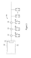
- FIG 3 is a block diagram of an alternative embodiment 180 of electric vehicle charging system 150.
- electric vehicle charging system 180 includes a central electric vehicle charging station 182 that is configured to charge multiple electric vehicles, for example, a first electric vehicle 184, a second electric vehicle 186, and/or a third electric vehicle 188.
- Electric vehicle charging station 182 may be positioned at or within an electric substation 190.
- Electric vehicle charging system 180 includes multiple connection stations, for example, a first connection station 192, a second connection station 194, and a third connection station 196, through which electric vehicles 184, 186, and 188 may be coupled to electric vehicle charging station 182.
- electric vehicle charging station 182 may include a single variable-output transformer and at least one switching device 198.
- Switching device 198 controls which of connection stations 192, 194, and 196 receives power. For example, it may be determined that electric vehicle 186 is to be provided with power first, electric vehicle 184 second, and electric vehicle 188 third. Electric vehicle charging station 182 first determines the maximum voltage level to provide electric vehicle 186 and provides power to second connection station 194 accordingly. Once charging of electric vehicle 186 is complete, or upon completion of a predetermined time limit, switching device 198 disconnects second connection station 194 from electric vehicle charging station 182. Electric vehicle charging station 182 determines the maximum voltage level to provide electric vehicle 184 and provides power to first connection station 192 accordingly.
- electric vehicle charging system 180 may include multiple switching devices positioned, for example, at connection stations 192, 194, and 196, and controlled to supply power to a selected connection station 192, 194, and 196. Furthermore, a switching device may be positioned at any suitable position within electric vehicle charging system 180 that allows system 180 to function as described herein.
- Figure 4 is a flow chart 200 of an example method 210 for controlling an electric vehicle charging station, for example, electric vehicle charging station 20 (shown in Figure 1 ).
- electric vehicle charging station 20 is configured for charging an electric vehicle, for example, electric vehicle 40 (shown in Figure 1 ).
- method 210 is a computer-implemented method, for example, a computer-implemented method executed by charging station controller 110 (shown in Figure 1 ).
- a computer program embodied on a computer readable medium includes at least one code segment, that when executed by a computer, for example, charging station controller 110, performs method 210. Aspects of the invention transform a general-purpose computer into a special-purpose computing device when configured to execute the instructions described herein.
- controller 110 may receive the voltage level signal from electric vehicle 40 using a communications channel, power line communications, and/or any other type of signal transmission that allows charging station 20 to function as described herein.
- Method 210 also includes providing 216 AC power to power converter 74 at the determined level of voltage.
- method 210 also includes providing 220 a switch actuation signal to a switching device, for example, switching device 82 (shown in Figure 1 ) positioned between power converter 74 and electric motor 70.
- switching device 82 shown in Figure 1
- switching device 82 uncouples electric motor 70 from power converter 74 and couples power converter 74 to electric vehicle charging station 20.
- Regulating 224 the power output may also include determining a level of power available from AC power source 52 and comparing the available power level to the power level predefined as needed for non-electric vehicle charging applications. Regulating 224 may also include determining the power output of electric vehicle charging station 20 (e.g., determining the charging voltage to provide) based on the difference between the available power level and the predefined power level. This may also be referred to as throttling of the charging voltage provided by charging station 20 to the electric vehicles.
- Controller 110 may be configured to regulate the power provided to a plurality of electric vehicles, for example, plurality of electric vehicles 152 (shown in Figures 2 and 3 ) so that the predefined level of power is available to non-electric vehicle charging loads.
- processor is intended to denote any machine capable of performing the calculations, or computations, necessary to perform the tasks of the invention.
- processor also is intended to denote any machine that is capable of accepting a structured input and of processing the input in accordance with prescribed rules to produce an output.
- phrase "configured to” as used herein means that the processor is equipped with a combination of hardware and software for performing the tasks of embodiments presented herein, as will be understood by those skilled in the art.
- Embodiments presented herein embrace one or more computer readable media, wherein each medium may be configured to include or includes thereon data or computer executable instructions for manipulating data.
- the computer executable instructions include data structures, objects, programs, routines, algorithms, or other program modules that may be accessed by a processing system, such as one associated with a general-purpose computer capable of performing various different functions or one associated with a special-purpose computer capable of performing a limited number of functions.
- Computer executable instructions cause the processing system to perform a particular function or group of functions and are examples of program code means for implementing steps for methods disclosed herein.
- a particular sequence of the executable instructions provides an example of corresponding acts that may be used to implement such steps.
- the methods and systems described herein can facilitate efficient and economical charging of electric vehicles.
- Example embodiments of methods and systems are described and/or illustrated herein in detail.
- the methods and systems are not limited to the specific embodiments described herein, but rather, components of each system, as well as steps of each method, may be utilized independently and separately from other components and steps described herein.
- Each component, and each method step can also be used in combination with other components and/or method steps.
- the articles “a”, “an”, “the”, and “said” are intended to mean that there are one or more of the element(s)/component(s)/etc.
- the terms “comprising”, “including”, and “having” are intended to be inclusive and mean that there may be additional element(s)/component(s)/etc. other than the listed element(s)/component(s)/etc.
Landscapes
- Engineering & Computer Science (AREA)
- Power Engineering (AREA)
- Transportation (AREA)
- Mechanical Engineering (AREA)
- Charge And Discharge Circuits For Batteries Or The Like (AREA)
- Electric Propulsion And Braking For Vehicles (AREA)
- Secondary Cells (AREA)
Applications Claiming Priority (1)
| Application Number | Priority Date | Filing Date | Title |
|---|---|---|---|
| US13/172,042 US9000721B2 (en) | 2011-06-29 | 2011-06-29 | Systems and methods for charging |
Publications (3)
| Publication Number | Publication Date |
|---|---|
| EP2540553A2 true EP2540553A2 (de) | 2013-01-02 |
| EP2540553A3 EP2540553A3 (de) | 2017-11-01 |
| EP2540553B1 EP2540553B1 (de) | 2023-09-27 |
Family
ID=46799989
Family Applications (1)
| Application Number | Title | Priority Date | Filing Date |
|---|---|---|---|
| EP12173724.1A Active EP2540553B1 (de) | 2011-06-29 | 2012-06-27 | Aufladesysteme und -verfahren |
Country Status (6)
| Country | Link |
|---|---|
| US (1) | US9000721B2 (de) |
| EP (1) | EP2540553B1 (de) |
| JP (1) | JP6114508B2 (de) |
| KR (1) | KR101925043B1 (de) |
| CN (1) | CN102931701B (de) |
| AU (1) | AU2012203809A1 (de) |
Cited By (2)
| Publication number | Priority date | Publication date | Assignee | Title |
|---|---|---|---|---|
| WO2019120684A1 (de) * | 2017-12-22 | 2019-06-27 | Siemens Aktiengesellschaft | Steuervorrichtung für eine ladeeinrichtung und verfahren zum steuern der ladeeinrichtung |
| SE2150806A1 (en) * | 2021-06-22 | 2022-12-23 | Ctek Sweden Ab | Method for communication between a battery charger and an electrically connected vehicle |
Families Citing this family (53)
| Publication number | Priority date | Publication date | Assignee | Title |
|---|---|---|---|---|
| US9847654B2 (en) | 2011-03-05 | 2017-12-19 | Powin Energy Corporation | Battery energy storage system and control system and applications thereof |
| US10536007B2 (en) | 2011-03-05 | 2020-01-14 | Powin Energy Corporation | Battery energy storage system and control system and applications thereof |
| US20130020993A1 (en) * | 2011-07-18 | 2013-01-24 | Green Charge Networks Llc | Multi-Mode Electric Vehicle Charging Station |
| KR101328622B1 (ko) * | 2011-12-23 | 2013-11-12 | (주)갑진 | 전원부 및 부하부 보호시스템 |
| DE102012007906A1 (de) * | 2012-04-23 | 2013-10-24 | Audi Ag | Verfahren zur Vorbereitung einer Energieversorgung eines Fahrzeugs |
| US20130339108A1 (en) * | 2012-06-14 | 2013-12-19 | Sap Ag | Managing demand charge tariffs for electric power |
| DE102012219673A1 (de) * | 2012-10-26 | 2014-04-30 | Robert Bosch Gmbh | Anordnung zur induktiven Energieübertragung an ein elektrisch antreibbares Fahrzeug |
| US20140239879A1 (en) * | 2013-02-22 | 2014-08-28 | Electro-Motive Diesel, Inc. | Battery charging system |
| US9457677B2 (en) | 2013-09-30 | 2016-10-04 | Elwha Llc | User interface to employment related information center associated with communication and control system and method for wireless electric vehicle electrical energy transfer |
| US10093194B2 (en) | 2013-09-30 | 2018-10-09 | Elwha Llc | Communication and control system and method regarding electric vehicle for wireless electric vehicle electrical energy transfer |
| US9205754B2 (en) | 2013-09-30 | 2015-12-08 | Elwha Llc | Communication and control regarding electricity provider for wireless electric vehicle electrical energy transfer |
| US9412515B2 (en) | 2013-09-30 | 2016-08-09 | Elwha, Llc | Communication and control regarding wireless electric vehicle electrical energy transfer |
| KR101493691B1 (ko) * | 2013-10-25 | 2015-02-17 | 한국에너지기술연구원 | 충전시스템 및 그 제어방법, 그리고 충전기 제어방법 |
| US9637017B2 (en) | 2013-10-25 | 2017-05-02 | Korea Institute Of Energy Research | Power-sharing charging system, charging device, and method for controlling the same |
| ES2837356T3 (es) * | 2013-11-06 | 2021-06-30 | Abb Schweiz Ag | Cargador para vehículos eléctricos con arbitraje de convertidor de energía distribuida |
| FR3014260B1 (fr) * | 2013-12-03 | 2016-01-01 | Renault Sas | Procede et systeme de commande d'un chargeur bidirectionnel d'une batterie de vehicule automobile. |
| AU2015280636B2 (en) * | 2014-06-27 | 2019-06-13 | Ergotron, Inc. | Electrical system for universal charging station |
| US10263436B2 (en) | 2014-10-20 | 2019-04-16 | Powin Energy Corporation | Electrical energy storage unit and control system and applications thereof |
| US10153521B2 (en) | 2015-08-06 | 2018-12-11 | Powin Energy Corporation | Systems and methods for detecting a battery pack having an operating issue or defect |
| US10254350B2 (en) | 2015-08-06 | 2019-04-09 | Powin Energy Corporation | Warranty tracker for a battery pack |
| US9923247B2 (en) | 2015-09-11 | 2018-03-20 | Powin Energy Corporation | Battery pack with integrated battery management system |
| WO2017041144A1 (en) * | 2015-09-11 | 2017-03-16 | Invertedpower Pty Ltd | A controller for an inductive load having one or more inductive windings |
| US10122186B2 (en) | 2015-09-11 | 2018-11-06 | Powin Energy Corporation | Battery management systems (BMS) having isolated, distributed, daisy-chained battery module controllers |
| US10040363B2 (en) * | 2015-10-15 | 2018-08-07 | Powin Energy Corporation | Battery-assisted electric vehicle charging system and method |
| US9882401B2 (en) | 2015-11-04 | 2018-01-30 | Powin Energy Corporation | Battery energy storage system |
| US10850627B2 (en) * | 2015-12-04 | 2020-12-01 | Cyberswitchingpatents, Llc | Electric vehicle charging system |
| US10843581B2 (en) * | 2015-12-04 | 2020-11-24 | Cyberswitchingpatents, Llc | Electric vehicle charging method |
| US11104246B2 (en) | 2015-12-04 | 2021-08-31 | Cyber Switching Solutions, Inc. | Electric vehicle charging system interface |
| US11180034B2 (en) * | 2015-12-04 | 2021-11-23 | Cyberswitchingpatents, Llc | Electric vehicle charging system with priority charging |
| US10300791B2 (en) * | 2015-12-18 | 2019-05-28 | Ge Global Sourcing Llc | Trolley interfacing device having a pre-charging unit |
| DE102016212543A1 (de) * | 2016-07-11 | 2018-01-11 | Continental Automotive Gmbh | Fahrzeugbordnetze, Ladesystem, Ladestation und Verfahren zur Übertragung von elektrischer Energie |
| US10699278B2 (en) | 2016-12-22 | 2020-06-30 | Powin Energy Corporation | Battery pack monitoring and warranty tracking system |
| EP3622608A4 (de) * | 2017-05-08 | 2021-01-27 | Invertedpower Pty Ltd | Fahrzeugladestation |
| US20180339601A1 (en) * | 2017-05-23 | 2018-11-29 | Martin Kruszelnicki | Charging station system and method |
| US10661659B2 (en) | 2017-06-21 | 2020-05-26 | Cyberswitchingpatents, LLC. | Integrated management of electric vehicle charging and non-electric vehicle fueling |
| WO2019011905A2 (en) * | 2017-07-10 | 2019-01-17 | Abb Schweiz Ag | VARIABLE POWER LOAD |
| US11545844B2 (en) * | 2017-09-08 | 2023-01-03 | Proterra Operating Company, Inc. | Limiting voltage spikes during electric vehicle charging |
| DE102017123071A1 (de) * | 2017-10-05 | 2019-04-11 | Dr. Ing. H.C. F. Porsche Aktiengesellschaft | Versorgung von Niedervolt-Bordnetzen von Fahrzeugen mit elektrischem Antrieb |
| US10882415B2 (en) * | 2017-12-04 | 2021-01-05 | General Electric Company | System and method of pre-charge testing to prevent misuse of electric vehicle charging station |
| DE102017130474A1 (de) * | 2017-12-19 | 2019-06-19 | Dr. Ing. H.C. F. Porsche Aktiengesellschaft | Transformatorvorrichtung für eine Ladestation für das elektrische Laden von Fahrzeugen mit wenigstens zwei Ladepunkten |
| DE102018104408A1 (de) * | 2018-02-27 | 2019-08-29 | Dr. Ing. H.C. F. Porsche Aktiengesellschaft | Verfahren und System zum Erkennen eines Fahrzeugtyps eines Fahrzeugs |
| DE102019111785A1 (de) * | 2019-05-07 | 2020-11-12 | Dr. Ing. H.C. F. Porsche Aktiengesellschaft | Verfahren und Vorrichtung zum Laden eines Elektrofahrzeugs mit einem Ladekabel |
| US11489356B2 (en) | 2019-07-02 | 2022-11-01 | Abb Schweiz Ag | MVDC link-powered battery chargers and operation thereof |
| US11772504B2 (en) * | 2019-08-22 | 2023-10-03 | Ioan Sasu | Fast rechargeable battery assembly and recharging equipment |
| KR102238043B1 (ko) * | 2019-10-16 | 2021-04-09 | 현대자동차주식회사 | 차량용 충전장치가 구비된 주차장의 주차안내 시스템 및 이를 이용한 주차안내 방법 |
| DE102019134508A1 (de) * | 2019-12-16 | 2021-06-17 | Dr. Ing. H.C. F. Porsche Aktiengesellschaft | Verfahren und Ladepark zu Lastmanagement mit Rückfalllösung |
| CN112421739B (zh) * | 2020-04-24 | 2024-01-02 | 葛炽昌 | 电动车交流充电系统 |
| US20220118863A1 (en) * | 2020-10-15 | 2022-04-21 | Rivian Ip Holdings, Llc | Charging station power sharing system and method |
| CN112838604B (zh) * | 2020-10-21 | 2022-03-25 | 国网河南省电力公司电力科学研究院 | 一种储能电站群参与电力系统agc的优化方法及系统 |
| TWI779443B (zh) * | 2020-12-28 | 2022-10-01 | 起而行綠能股份有限公司 | 電動車輛充電主動式回復系統 |
| US20220410755A1 (en) * | 2021-06-25 | 2022-12-29 | Zoox, Inc. | Fleet charging station architecture |
| US20230011000A1 (en) * | 2021-07-08 | 2023-01-12 | Enersys Delaware Inc. | Direct current fast charging systems with grid tied energy storage systems |
| CN113859023B (zh) * | 2021-10-13 | 2024-04-19 | 贵州师范大学 | 减少电动汽车充电桩空载损耗的三级自动控制系统及电路 |
Family Cites Families (32)
| Publication number | Priority date | Publication date | Assignee | Title |
|---|---|---|---|---|
| KR930011132B1 (ko) | 1991-11-01 | 1993-11-24 | 삼성전자 주식회사 | 배터리의 쾌속충전 제어회로 |
| DE4236286A1 (de) * | 1992-10-28 | 1994-05-05 | Daimler Benz Ag | Verfahren und Anordnung zum automatischen berührungslosen Laden |
| JPH07123601A (ja) * | 1993-10-20 | 1995-05-12 | Sanpo Denki Kk | 充電器 |
| US5548200A (en) * | 1994-07-06 | 1996-08-20 | Norvik Traction Inc. | Universal charging station and method for charging electric vehicle batteries |
| US5594318A (en) * | 1995-04-10 | 1997-01-14 | Norvik Traction Inc. | Traction battery charging with inductive coupling |
| DE69714879T2 (de) * | 1996-01-30 | 2003-05-08 | Sumitomo Wiring Systems | Verbindungssystem mit zugehörigem Verfahren |
| JP2000341887A (ja) * | 1999-03-25 | 2000-12-08 | Toyota Autom Loom Works Ltd | 給電用カプラ、給電装置、受電器及び電磁誘導型非接触充電装置 |
| AU6143900A (en) | 1999-07-19 | 2001-02-05 | Vladimir Petrovic | Rapid battery charging method and apparatus |
| CN2468205Y (zh) * | 2001-02-05 | 2001-12-26 | 薛建南 | 电动车电源充电器 |
| KR100405710B1 (ko) * | 2001-06-26 | 2003-11-14 | 현대자동차주식회사 | 전기 자동차의 배터리 충전 장치 |
| US6664762B2 (en) | 2001-08-21 | 2003-12-16 | Power Designers, Llc | High voltage battery charger |
| EP1451921A4 (de) | 2001-11-02 | 2006-01-11 | Aker Wade Power Technologies L | Schnelles ladegerät für batterien mit hoher kapazität |
| US6963186B2 (en) * | 2003-02-28 | 2005-11-08 | Raymond Hobbs | Battery charger and method of charging a battery |
| US7135836B2 (en) | 2003-03-28 | 2006-11-14 | Power Designers, Llc | Modular and reconfigurable rapid battery charger |
| DE10328588A1 (de) * | 2003-06-25 | 2005-03-24 | Siemens Ag | Fernbedienung zur Abgabe von Befehlen an ein fernbedienbares Gerät |
| JP4770798B2 (ja) * | 2007-06-15 | 2011-09-14 | 株式会社豊田自動織機 | 電源装置 |
| JP5092730B2 (ja) * | 2007-12-19 | 2012-12-05 | マツダ株式会社 | バッテリの充電方法および充電制御装置 |
| JP4332861B2 (ja) * | 2008-01-16 | 2009-09-16 | トヨタ自動車株式会社 | 車両の充電制御装置 |
| JP4561878B2 (ja) * | 2008-06-05 | 2010-10-13 | トヨタ自動車株式会社 | 蓄電装置を搭載する車両および充電ケーブル |
| US8080973B2 (en) * | 2008-10-22 | 2011-12-20 | General Electric Company | Apparatus for energy transfer using converter and method of manufacturing same |
| JP2010130848A (ja) * | 2008-11-28 | 2010-06-10 | Toshiba Corp | 電力伝送装置 |
| US8324859B2 (en) * | 2008-12-15 | 2012-12-04 | Comverge, Inc. | Method and system for co-operative charging of electric vehicles |
| WO2010131348A1 (ja) * | 2009-05-14 | 2010-11-18 | トヨタ自動車株式会社 | 車両用充電装置 |
| US8013570B2 (en) * | 2009-07-23 | 2011-09-06 | Coulomb Technologies, Inc. | Electrical circuit sharing for electric vehicle charging stations |
| US7782015B1 (en) * | 2009-07-30 | 2010-08-24 | Billy Joe Aaron | Electric power system |
| DE102009036816A1 (de) * | 2009-08-10 | 2011-02-17 | Rwe Ag | Steuerung von Ladestationen |
| CA2780084A1 (en) * | 2009-11-06 | 2011-05-12 | Inda S.R.L. | Electric drive and battery-charging power electronic system |
| US8686685B2 (en) * | 2009-12-25 | 2014-04-01 | Golba, Llc | Secure apparatus for wirelessly transferring power and communicating with one or more slave devices |
| US8483628B2 (en) * | 2010-06-03 | 2013-07-09 | Broadcom Corporation | Multiple-phase frequency translated filter |
| CN201752076U (zh) * | 2010-06-10 | 2011-02-23 | 上海市电力公司 | 一种v2g智能充放电装置 |
| CN102025182B (zh) * | 2010-11-30 | 2012-10-31 | 梁一桥 | 多功能电动汽车动力电池组模块化充放电系统 |
| US9225197B2 (en) * | 2011-05-06 | 2015-12-29 | Tesla Motors, Inc. | Charging efficiency using variable isolation |
-
2011
- 2011-06-29 US US13/172,042 patent/US9000721B2/en active Active
-
2012
- 2012-06-27 JP JP2012143962A patent/JP6114508B2/ja active Active
- 2012-06-27 EP EP12173724.1A patent/EP2540553B1/de active Active
- 2012-06-28 AU AU2012203809A patent/AU2012203809A1/en not_active Abandoned
- 2012-06-28 KR KR1020120070044A patent/KR101925043B1/ko active IP Right Grant
- 2012-06-29 CN CN201210410284.2A patent/CN102931701B/zh active Active
Non-Patent Citations (1)
| Title |
|---|
| None |
Cited By (2)
| Publication number | Priority date | Publication date | Assignee | Title |
|---|---|---|---|---|
| WO2019120684A1 (de) * | 2017-12-22 | 2019-06-27 | Siemens Aktiengesellschaft | Steuervorrichtung für eine ladeeinrichtung und verfahren zum steuern der ladeeinrichtung |
| SE2150806A1 (en) * | 2021-06-22 | 2022-12-23 | Ctek Sweden Ab | Method for communication between a battery charger and an electrically connected vehicle |
Also Published As
| Publication number | Publication date |
|---|---|
| US9000721B2 (en) | 2015-04-07 |
| KR20130002956A (ko) | 2013-01-08 |
| US20130002197A1 (en) | 2013-01-03 |
| KR101925043B1 (ko) | 2019-02-27 |
| AU2012203809A1 (en) | 2013-01-17 |
| EP2540553A3 (de) | 2017-11-01 |
| JP2013013314A (ja) | 2013-01-17 |
| CN102931701B (zh) | 2016-12-21 |
| JP6114508B2 (ja) | 2017-04-12 |
| CN102931701A (zh) | 2013-02-13 |
| EP2540553B1 (de) | 2023-09-27 |
Similar Documents
| Publication | Publication Date | Title |
|---|---|---|
| US9000721B2 (en) | Systems and methods for charging | |
| KR102586914B1 (ko) | 차량 배터리 충전용 전력 변환 장치 및 이의 제어 방법 | |
| US10166877B2 (en) | Charge control system for electric vehicle and electric vehicle | |
| US10059210B2 (en) | Vehicle mutual-charging system and charging connector | |
| US9845021B2 (en) | On-vehicle power supply system and electric vehicle | |
| CN103492214B (zh) | 电动车辆的电源装置及其控制方法 | |
| CN102195330B (zh) | 电池充电电路和充电方法 | |
| CN109414997B (zh) | 车辆车载电网、充电系统、充电站和用于传输电能的方法 | |
| CN103189230B (zh) | 电动车辆的电源装置及其控制方法以及电动车辆 | |
| US20180131220A1 (en) | Vehicle-side charging circuit for a vehicle with electric drive, and method for operating a vehicle-side current converter, and use of at least one winding of a vehicle-side electric machine for intermediate storagectrical machine for buffer | |
| US20170282747A1 (en) | Charging system for vehicle battery | |
| CN112389269B (zh) | 一种汽车、能量转换装置及能量转换方法 | |
| US9365122B2 (en) | Onboard power line conditioning system for an electric or hybrid vehicle | |
| US9862287B2 (en) | Power system for electric vehicle, electric vehicle and motor controller | |
| KR20210156107A (ko) | 차량용 배터리 충전 장치 및 방법 | |
| Rodrigues et al. | Simultaneous active power filter and G2V (or V2G) operation of EV on-board power electronics | |
| US9744868B2 (en) | Electric circuit for charging at least one electrical energy storage unit by means of an electrical network | |
| CN112550072B (zh) | 用于电驱动车辆的能量系统 | |
| CN113043869A (zh) | 车辆用电池系统以及其的操作方法 | |
| KR101606584B1 (ko) | 전력을 공유하는 충전 시스템, 충전 장치 및 그 제어 방법 | |
| CN209805483U (zh) | 一种车载充电装置及汽车 | |
| KR101558329B1 (ko) | 전력을 공유하는 충전 시스템, 충전 장치 및 그 제어 방법 |
Legal Events
| Date | Code | Title | Description |
|---|---|---|---|
| PUAI | Public reference made under article 153(3) epc to a published international application that has entered the european phase |
Free format text: ORIGINAL CODE: 0009012 |
|
| AK | Designated contracting states |
Kind code of ref document: A2 Designated state(s): AL AT BE BG CH CY CZ DE DK EE ES FI FR GB GR HR HU IE IS IT LI LT LU LV MC MK MT NL NO PL PT RO RS SE SI SK SM TR |
|
| AX | Request for extension of the european patent |
Extension state: BA ME |
|
| PUAL | Search report despatched |
Free format text: ORIGINAL CODE: 0009013 |
|
| AK | Designated contracting states |
Kind code of ref document: A3 Designated state(s): AL AT BE BG CH CY CZ DE DK EE ES FI FR GB GR HR HU IE IS IT LI LT LU LV MC MK MT NL NO PL PT RO RS SE SI SK SM TR |
|
| AX | Request for extension of the european patent |
Extension state: BA ME |
|
| RIC1 | Information provided on ipc code assigned before grant |
Ipc: B60L 11/18 20060101AFI20170928BHEP |
|
| STAA | Information on the status of an ep patent application or granted ep patent |
Free format text: STATUS: REQUEST FOR EXAMINATION WAS MADE |
|
| 17P | Request for examination filed |
Effective date: 20180502 |
|
| RBV | Designated contracting states (corrected) |
Designated state(s): AL AT BE BG CH CY CZ DE DK EE ES FI FR GB GR HR HU IE IS IT LI LT LU LV MC MK MT NL NO PL PT RO RS SE SI SK SM TR |
|
| STAA | Information on the status of an ep patent application or granted ep patent |
Free format text: STATUS: EXAMINATION IS IN PROGRESS |
|
| 17Q | First examination report despatched |
Effective date: 20190214 |
|
| STAA | Information on the status of an ep patent application or granted ep patent |
Free format text: STATUS: EXAMINATION IS IN PROGRESS |
|
| STAA | Information on the status of an ep patent application or granted ep patent |
Free format text: STATUS: EXAMINATION IS IN PROGRESS |
|
| REG | Reference to a national code |
Ref country code: DE Ref legal event code: R079 Ref document number: 602012080132 Country of ref document: DE Free format text: PREVIOUS MAIN CLASS: B60L0011180000 Ipc: B60L0053240000 Ref country code: DE Ipc: B60L0053240000 |
|
| RIC1 | Information provided on ipc code assigned before grant |
Ipc: B60L 53/24 20190101AFI20230307BHEP |
|
| GRAP | Despatch of communication of intention to grant a patent |
Free format text: ORIGINAL CODE: EPIDOSNIGR1 |
|
| STAA | Information on the status of an ep patent application or granted ep patent |
Free format text: STATUS: GRANT OF PATENT IS INTENDED |
|
| INTG | Intention to grant announced |
Effective date: 20230418 |
|
| GRAS | Grant fee paid |
Free format text: ORIGINAL CODE: EPIDOSNIGR3 |
|
| GRAA | (expected) grant |
Free format text: ORIGINAL CODE: 0009210 |
|
| STAA | Information on the status of an ep patent application or granted ep patent |
Free format text: STATUS: THE PATENT HAS BEEN GRANTED |
|
| AK | Designated contracting states |
Kind code of ref document: B1 Designated state(s): AL AT BE BG CH CY CZ DE DK EE ES FI FR GB GR HR HU IE IS IT LI LT LU LV MC MK MT NL NO PL PT RO RS SE SI SK SM TR |
|
| REG | Reference to a national code |
Ref country code: GB Ref legal event code: FG4D |
|
| REG | Reference to a national code |
Ref country code: CH Ref legal event code: EP |
|
| REG | Reference to a national code |
Ref country code: DE Ref legal event code: R096 Ref document number: 602012080132 Country of ref document: DE |
|
| REG | Reference to a national code |
Ref country code: IE Ref legal event code: FG4D |
|
| REG | Reference to a national code |
Ref country code: LT Ref legal event code: MG9D |
|
| PG25 | Lapsed in a contracting state [announced via postgrant information from national office to epo] |
Ref country code: GR Free format text: LAPSE BECAUSE OF FAILURE TO SUBMIT A TRANSLATION OF THE DESCRIPTION OR TO PAY THE FEE WITHIN THE PRESCRIBED TIME-LIMIT Effective date: 20231228 |
|
| PG25 | Lapsed in a contracting state [announced via postgrant information from national office to epo] |
Ref country code: SE Free format text: LAPSE BECAUSE OF FAILURE TO SUBMIT A TRANSLATION OF THE DESCRIPTION OR TO PAY THE FEE WITHIN THE PRESCRIBED TIME-LIMIT Effective date: 20230927 Ref country code: RS Free format text: LAPSE BECAUSE OF FAILURE TO SUBMIT A TRANSLATION OF THE DESCRIPTION OR TO PAY THE FEE WITHIN THE PRESCRIBED TIME-LIMIT Effective date: 20230927 Ref country code: NO Free format text: LAPSE BECAUSE OF FAILURE TO SUBMIT A TRANSLATION OF THE DESCRIPTION OR TO PAY THE FEE WITHIN THE PRESCRIBED TIME-LIMIT Effective date: 20231227 Ref country code: LV Free format text: LAPSE BECAUSE OF FAILURE TO SUBMIT A TRANSLATION OF THE DESCRIPTION OR TO PAY THE FEE WITHIN THE PRESCRIBED TIME-LIMIT Effective date: 20230927 Ref country code: LT Free format text: LAPSE BECAUSE OF FAILURE TO SUBMIT A TRANSLATION OF THE DESCRIPTION OR TO PAY THE FEE WITHIN THE PRESCRIBED TIME-LIMIT Effective date: 20230927 Ref country code: GR Free format text: LAPSE BECAUSE OF FAILURE TO SUBMIT A TRANSLATION OF THE DESCRIPTION OR TO PAY THE FEE WITHIN THE PRESCRIBED TIME-LIMIT Effective date: 20231228 Ref country code: FI Free format text: LAPSE BECAUSE OF FAILURE TO SUBMIT A TRANSLATION OF THE DESCRIPTION OR TO PAY THE FEE WITHIN THE PRESCRIBED TIME-LIMIT Effective date: 20230927 |
|
| REG | Reference to a national code |
Ref country code: NL Ref legal event code: MP Effective date: 20230927 |
|
| REG | Reference to a national code |
Ref country code: AT Ref legal event code: MK05 Ref document number: 1615100 Country of ref document: AT Kind code of ref document: T Effective date: 20230927 |
|
| PG25 | Lapsed in a contracting state [announced via postgrant information from national office to epo] |
Ref country code: NL Free format text: LAPSE BECAUSE OF FAILURE TO SUBMIT A TRANSLATION OF THE DESCRIPTION OR TO PAY THE FEE WITHIN THE PRESCRIBED TIME-LIMIT Effective date: 20230927 |
|
| PG25 | Lapsed in a contracting state [announced via postgrant information from national office to epo] |
Ref country code: IS Free format text: LAPSE BECAUSE OF FAILURE TO SUBMIT A TRANSLATION OF THE DESCRIPTION OR TO PAY THE FEE WITHIN THE PRESCRIBED TIME-LIMIT Effective date: 20240127 |
|
| PG25 | Lapsed in a contracting state [announced via postgrant information from national office to epo] |
Ref country code: AT Free format text: LAPSE BECAUSE OF FAILURE TO SUBMIT A TRANSLATION OF THE DESCRIPTION OR TO PAY THE FEE WITHIN THE PRESCRIBED TIME-LIMIT Effective date: 20230927 |
|
| PG25 | Lapsed in a contracting state [announced via postgrant information from national office to epo] |
Ref country code: ES Free format text: LAPSE BECAUSE OF FAILURE TO SUBMIT A TRANSLATION OF THE DESCRIPTION OR TO PAY THE FEE WITHIN THE PRESCRIBED TIME-LIMIT Effective date: 20230927 |
|
| PG25 | Lapsed in a contracting state [announced via postgrant information from national office to epo] |
Ref country code: SM Free format text: LAPSE BECAUSE OF FAILURE TO SUBMIT A TRANSLATION OF THE DESCRIPTION OR TO PAY THE FEE WITHIN THE PRESCRIBED TIME-LIMIT Effective date: 20230927 Ref country code: RO Free format text: LAPSE BECAUSE OF FAILURE TO SUBMIT A TRANSLATION OF THE DESCRIPTION OR TO PAY THE FEE WITHIN THE PRESCRIBED TIME-LIMIT Effective date: 20230927 Ref country code: IS Free format text: LAPSE BECAUSE OF FAILURE TO SUBMIT A TRANSLATION OF THE DESCRIPTION OR TO PAY THE FEE WITHIN THE PRESCRIBED TIME-LIMIT Effective date: 20240127 Ref country code: ES Free format text: LAPSE BECAUSE OF FAILURE TO SUBMIT A TRANSLATION OF THE DESCRIPTION OR TO PAY THE FEE WITHIN THE PRESCRIBED TIME-LIMIT Effective date: 20230927 Ref country code: EE Free format text: LAPSE BECAUSE OF FAILURE TO SUBMIT A TRANSLATION OF THE DESCRIPTION OR TO PAY THE FEE WITHIN THE PRESCRIBED TIME-LIMIT Effective date: 20230927 Ref country code: CZ Free format text: LAPSE BECAUSE OF FAILURE TO SUBMIT A TRANSLATION OF THE DESCRIPTION OR TO PAY THE FEE WITHIN THE PRESCRIBED TIME-LIMIT Effective date: 20230927 Ref country code: AT Free format text: LAPSE BECAUSE OF FAILURE TO SUBMIT A TRANSLATION OF THE DESCRIPTION OR TO PAY THE FEE WITHIN THE PRESCRIBED TIME-LIMIT Effective date: 20230927 Ref country code: SK Free format text: LAPSE BECAUSE OF FAILURE TO SUBMIT A TRANSLATION OF THE DESCRIPTION OR TO PAY THE FEE WITHIN THE PRESCRIBED TIME-LIMIT Effective date: 20230927 Ref country code: PT Free format text: LAPSE BECAUSE OF FAILURE TO SUBMIT A TRANSLATION OF THE DESCRIPTION OR TO PAY THE FEE WITHIN THE PRESCRIBED TIME-LIMIT Effective date: 20240129 |